Silk fibroin–keratin based 3D scaffolds as a dermal substitute for skin tissue engineering
Nandana
Bhardwaj
abc,
Wan Ting
Sow
a,
Dipali
Devi
c,
Kee Woei
Ng
*a,
Biman B.
Mandal
*d and
Nam-Joon
Cho
*abe
aSchool of Materials Science and Engineering, Nanyang Technological University, Singapore-639798. E-mail: njcho@ntu.edu.sg
bCentre for Biomimetic Sensor Science, Nanyang Technological University, Singapore-639553
cSeri-Biotechnology Unit, Life Science Division, Institute of Advanced Study in Science and Technology, Guwahati-781035, India. E-mail: nandana.bhardwaj@gmail.com
dDepartment of Biotechnology, Indian Institute of Technology Guwahati, Guwahati-781039, India. E-mail: biman.mandal@iitg.ernet.in
eSchool of Chemical and Biomedical Engineering, Nanyang Technological University, Singapore-639798
First published on 29th October 2014
Abstract
Development of highly vascular dermal tissue-engineered skin substitutes with appropriate mechanical properties and cellular cues is in need for significant advancement in the field of dermal reconstruction. Limitations have been imposed on natural biomaterials despite their superb biocompatibility hence, studies in biomaterial blending have been ongoing. Herein, we investigated blends of silk fibroin and human hair-derived keratin as wound-healing substrates that promote enhanced fibroblast cell adhesion and proliferation. Three-dimensional (3D) blended scaffolds were fabricated by freeze-drying, and their physico-chemical, mechanical and degradable properties were extensively characterized. Cytocompatibility tests observing cell adhesion and cell proliferation have shown significant enhancements in blended scaffolds. Also, its structural composition with high porosity (>85%) and interconnected pores in the range of 100–120 microns further confirms the superiority of the complex compared to its counterparts. FTIR studies identified the enhanced stability within its structure and were followed-up with sequential experiments to demonstrate improved thermal, degradation, and mechanical properties. Furthermore, immunohistochemical staining revealed greater expression of collagen type I in the cultured cells, indicating functional fibroblast proliferation and, hence, the exciting potential of this construct for dermal applications. Taken together, this study demonstrates the promising attributes from blended biomaterials and specifically present silk fibroin and human hair keratin blended scaffolds as a promising dermal substitute for skin tissue engineering.
Insight, innovation, integrationBiocomposite scaffolds afford new capabilities for tissue engineering applications by integrating the biological and mechanical traits of two or more materials. Here, we report the development of a vascularized skin tissue mimic based on a three-dimensional scaffold comprised of blended silk fibroin and human hair keratin. The tunable scaffold combines the superior material properties of silk with signaling cues present in keratin. Compared to silk scaffolds, the blended scaffolds demonstrate enhanced mechanical properties and support improved fibroblast attachment, growth, and matrix accumulation. In summary, the findings provide a quantitative connection linking modulation of component properties with the complex behavior of cells, and support the potential of biocomposite scaffolds of this kind as skin substitutes and platforms to investigate wound healing. |
Introduction
Skin, the largest and highly complex organ in vertebrates, is mainly composed of two layers, epidermis and dermis.1 It plays a vital role in protecting the body against chemical or mechanical damage, aiding sensory detection, maintaining fluid homeostasis, and promoting self-healing.2,3 The keratinized and stratified epidermis is mainly composed of keratinocytes to form the vital surface barrier layer, and appendages including sebaceous and sweat glands to help maintain homeostasis.4 The dermis is an underlying, vascularized, collagen-rich, connective tissue, which provides strength and nourishment to the epidermis and constitutes the bulk of the skin. The most prominent part of the dermis is the extracellular matrix (ECM) composed of collagen (type I and III), elastin, and glycosaminoglycans (GAG), playing a major role in the biomechanics of the skin. Fibroblasts are the major cell types present in the dermis responsible for producing the ECM and also remodelling enzymes such as matrix metalloproteinases and collagenases which facilitate wound healing.5–7 The loss of dermal tissues from exposure to acute or chronic wounds, thus, may cause impairment in the healing process due to the loss of fibroblasts.8,9 Attempts in skin repair had been achieved through various treatments including skin grafts (autografts or allografts), skin replacement, reconstructive surgery, and wound dressing, however, all have shown shortcomings such as donor limitations, immune rejection, lack of appendices, and scarring.10–14 As an alternative approach, skin replacement using tissue engineering and regenerative medicine have gained much attention, especially, with delivery of promising results from translational research in skin defect restoration.15–20 The tissue engineering approach has helped develop various models for skin epidermis and dermis reconstruction.21–23Effective dermal substitutes should have appropriate structural, mechanical, and functional properties. Additionally, these substitutes should enhance the ability to promote ECM formation and boost angiogenesis for a sustainable wound healing process.24 A wide variety of natural and synthetic biomaterials such as silk fibroin, collagen, chitosan, hyaluronic acid, poly glycolic acid (PGA), and poly lactic-co-glycolic acid (PLGA) have been studied, tested, and utilized as skin substitutes.6,18,19,25–29 Natural polymers have shown superiority in biomedical applications since they have proven to be most compatible with the native ECM. Despite the compatibility, all polymers were insufficient in delivering the desired performances in one or more aspects. Herein, we have developed a novel blended scaffold system of two natural polymers, silk fibroin (SF) and human hair keratin (KR), which in theory would enhance the shortcomings of pure silk scaffolds, and evaluated its potential for dermal reconstruction.
SF is a fibrous natural polymeric biomaterial obtained from silkworms and spiders with attractive properties for translational applications.30–33 SF biomaterial is available in different forms including films, scaffolds, hydrogels, and electrospun fibers. This has been extensively used for various tissue engineering applications, especially for skin, due to its high mechanical strength, excellent biocompatibility, and biodegradability.34–40 There are studies reporting SF film utilization in wound dressings for healing of full-thickness skin wounds in rats.41 In other case studies, the effectiveness of electrospun SF matrices in wound healing has been reported.42,43 Also recently, the use of electrospun nanofibrous SF patches has demonstrated improved wound healing in diabetic mice.44 Despite the various studies of its benefits, shortage of cell specific-binding sites and limited growth factor-adsorbing capacity are indicating that silk fibroin, alone, may be insufficient for dermal tissue regeneration.29 Therefore, investigations in the blending of silk fibroin with other polymers have been suggested in order to improve the functional shortcomings while taking advantage of the structural benefits from using SF as a dermal alternative. SF/KR blended films, SF/alginate sponges, and SF/chondroitin sulfate/hyaluronic acid blended scaffolds are a few of many ongoing products that have shown higher healing efficacy compared to the individual components.29,45,46
KR's are cysteine-rich intermediate filament proteins found in the cytoskeleton of the epithelial cells and in the matrix of hair, feathers, wool, nails and horns.47,48 The natural abundance of cell adhesion sequences, RGD (Arg-Gly-Asp) and LDV (Leu-Asp-Val), makes it suitable as a biomaterial for tissue engineering applications.49,50 Moreover, KR is biocompatible and biodegradable and is able to accelerate the ECM production in fibroblasts growth.49 There are now reports of KR in the form of coating, sponge, film, hydrogel, and electrospun fibers that are being developed and utilized for biomedical applications.51–54 However, KR dissociated from skin appendages is found to show poor mechanical properties, limiting its applications in tissue engineering. Hence, the blending of biomaterials to improve its physico-chemical properties becomes inevitable. So far, there have been studies on beneficial properties of silk fibroin–keratin (SFKR) blended films and fibers.55,56 Yet, the utilization of SFKR composite scaffolds for dermal reconstruction has not been studied.
The purpose of this study is to show that a bioactive 3D SFKR hybrid scaffold would have beneficial properties of each individual biomaterial while complementing the shortcomings, making this a superior scaffold for in vitro dermal tissue reconstruction. To test this hypothesis, we have designed and tested SFKR composite scaffolds with the desirable morphological and mechanical properties necessary to mimic the native cell viability, adhesion, proliferation and biocompatibility for in vitro skin tissue engineering dermal substitute studies. For comparison, freeze-dried and freeze-gelled pure silk fibroin scaffolds were used in the study along with the blended scaffolds.
Materials and methods
Materials
Bombyx mori silkworm fresh cocoons were collected from Central Silk Board, Bangalore. Keratin was extracted from human hair. Cell culture grade chemicals including Dulbecco's modified Eagle's medium (DMEM), fetal bovine serum (FBS), Trypsin–EDTA, HEPES, L-glutamine and penicillin–streptomycin were purchased from Gibco BRL Rockville, MD, USA. Rhodamine phalloidine (Invitrogen), Hoechst 33342 (Sigma), MTT (Sigma), Alamar blue (Invitrogen), anti-collagen I monoclonal antibody (Abcam), Vactastain universal elite kit (Vector labs), DAB (Vector labs), Cellulose dialysis membrane (MWCO-12 kDa) (Sigma), Lithum bromide (Sigma), and other chemicals used were of analytical grade.Preparation of SF solution
SF solution was prepared by following the method of Sofia et al.,57 with slight modification. Briefly, silk cocoons were cut into pieces, degummed in 0.02 M Na2CO3 solution under boiling conditions for 30 min to remove sericin. Fibers were further washed with deionized water and then kept at 37 °C overnight for drying. Purified fibroin fibers were dissolved in 9.3 M LiBr and then dialyzed against MilliQ-treated water using a 12 kDa molecular weight cut-off cellulose dialysis membrane. Dialysis was carried out to remove LiBr from the SF solution with frequent change of water at a regular time interval. The final concentration of the SF solution was 2 wt% as determined gravimetrically.Preparation of KR solution
KR was extracted from human hair as previously described.52 Hair samples were washed with soap and 70% ethanol, rinsed with water then air-dried. Delipidization was achieved by bathing the sample in a chloroform and methanol (2![[thin space (1/6-em)]](https://www.rsc.org/images/entities/char_2009.gif) :
:![[thin space (1/6-em)]](https://www.rsc.org/images/entities/char_2009.gif) 1 v/v) mixture for 24 hours at room temperature. Delipidized hair was cut into small fragments. For each extraction, 50 g of hair fragments were immersed in 1 L of 0.125 M sodium sulfide (Na2S) solution and incubated at 40 °C for four hours. The resulting mixture was filtered and exhaustively dialyzed against deionized water in cellulose tubing for 2–3 days. The concentrations of resulting KR solutions after dialysis were determined by routine protein quantification assays. The final concentration of the KR solution was 2 wt%.
1 v/v) mixture for 24 hours at room temperature. Delipidized hair was cut into small fragments. For each extraction, 50 g of hair fragments were immersed in 1 L of 0.125 M sodium sulfide (Na2S) solution and incubated at 40 °C for four hours. The resulting mixture was filtered and exhaustively dialyzed against deionized water in cellulose tubing for 2–3 days. The concentrations of resulting KR solutions after dialysis were determined by routine protein quantification assays. The final concentration of the KR solution was 2 wt%.
Fabrication of scaffolds
Scanning electron microscopy (SEM)
Scaffolds were cut and sputter coated with gold and analyzed using SEM (JSM 5410). The pore size was determined using the ImageJ software (Wayne Rasband, National Institute of Health, USA). A minimum of 30 pores was examined per scaffold.Swelling studies
Swelling studies were done with all three scaffolds. Briefly, the scaffolds were weighed in the dry state on an electronic precision balance, and then immersed in 10 mL ELIX water. At various time intervals, soaked scaffolds were taken out carefully and weighed in the swollen state. The experiments were conducted in sets of three under identical conditions.The degree of swelling (Q) of these samples was calculated using the following equation
| Q = (Ws − Wd)/Wd, |
Porosity determination
The porosity of the SF and SFKR blended scaffolds was measured by the liquid displacement method. The scaffolds were immersed in a known volume (V1) of hexane in a graduated cylinder for five minutes. The total volume of hexane and the hexane-impregnated scaffold was recorded as V2. The hexane-impregnated scaffolds were then removed from the cylinder and the residual hexane volume was recorded as V3. For all types of scaffolds the experiment was carried out in triplicates.The total volume of the scaffold was determined using
| V = (V2 − V1) + (V1 − V3) = (V2 − V3), |
The porosity of the scaffold (ε) was obtained by
| ε (%) = (V1 − V3)/(V2 − V3) × 100 |
Fourier transform infrared (FTIR) spectroscopy
FTIR measurements were made using a Frontier™ IR/NIR FTIR (Perkin Elmer) spectrophotometer in the spectral region 500–4000 cm−1. For each measurement 32 interferograms were co-added and Fourier transformed at a resolution of 4 cm−1. All absorbance spectra were recorded at room temperature and analyzed using Microcal Origin Version 6.0.Characterization of thermal properties
Integral stability
The integral stabilities of the constructs were evaluated by studying the in vitro release of the protein from the constructs. The constructs were immersed in 10 mL ELIX water in triplicate and the protein release in water was estimated by the Bradford method. Briefly, the leached protein samples were collected at regular intervals and mixed with Bradford reagent and vortexed. The absorbance for protein was taken at 595 nm. The protein release was estimated over a period of time.Mechanical testing
The compressive mechanical properties of scaffolds were tested using a Universal Testing machine, Instron 5567 equipped with a 0.5 kN load cell at ambient room temperature using modification of ASTM method F451-95. The samples were presoaked in PBS for two hours and were examined with a crosshead speed of 1 mm min−1. At least three specimens were tested for each sample group, and the mean values with standard deviations are reported.In vitro degradation
In vitro degradation of regenerated SF scaffolds was evaluated for 28 days using Protease XIV from S. griseus with an activity of 2 U mL−1. SFFD, SFKR and SFFG scaffolds measuring 10 mm in diameter, and ∼2 mm in height were immersed in 5 mL of phosphate buffered saline (pH 7.4) containing 2 U mL−1 protease enzyme. The samples were incubated at 37 °C to mimic the in vivo conditions. The enzyme solution was replaced with freshly prepared solution every 72 hours. All three types of scaffolds were also immersed in PBS (pH 7.4) without enzyme under similar incubation conditions for comparison.The percentage loss in weight was determined by the formula:
| % loss = [Wi − Wt]/Wi × 100; |
Cell culture and seeding
Cell viability determination using MTT assay
Cell viability and cytocompatibility assessment were carried out using MTT assay. SFFD, SFFG and SFKR scaffolds were pre-sterilized and were conditioned in DMEM for two hours before cell seeding. Equal number of cells (5 × 10⁵) was seeded on each scaffold. In brief, total cells (5 × 10⁵) were suspended in 20 μL medium and seeded. After four hours of initial cell attachment, the seeded scaffolds were transferred to fresh culture plates containing medium. Fresh medium was replenished every alternate day and the culture was incubated for 1, 3, 5, 7 and 14 days in a humidified atmosphere containing 5% CO2 at 37 °C. On specified days, the cell viability was evaluated using MTT assay.Scanning electron microscopy (SEM) for observation of cell growth and attachment
Seeded scaffolds were characterized for cell growth and attachment after 7 and 14 days of culture. Scaffolds were fixed with 4% paraformaldehyde for one hour and then dehydrated with gradation of ethanol followed by treatment with isoamyl acetate and vacuum drying. Finally scaffolds were sputter-coated with gold, and observed by SEM (JEOL 5410).Fluorescence microscopy
Attachment of murine fibroblast cells on SFFD, SFFG and SFKR scaffolds was revealed using fluorescence microscopy. The matrices were seeded with fibroblast cells (5 × 10⁵) and cultured for 14 days. After 14 days, matrices were harvested and washed with PBS (pH 7.4) three times, followed by incubation in 4% paraformaldehyde in PBS for 10 minutes. The samples were further washed with PBS and pre-incubated with 1% bovine serum albumin (BSA) for 30 minutes in order to avoid any non-specific binding. The constructs were then permeabilized using 0.1% Triton X-100 for five minutes. Constructs were stained with rhodamine phalloidin for 20 minutes at room temperature, followed by washing with PBS and staining with 5 mg mL−1 Hoechst 33342 for 30 minutes. Fluorescence images from stained constructs were obtained using a fluorescence microscope (Leica DMI3000B).Immunohistochemical (IHC) analysis for localization of collagen I
Constructs were analyzed by IHC to qualitatively localize and evaluate the extent of type I collagen (Col I) deposition.37 Construct sections (5 μm) were fixed with acetone at 4 °C for 15 minutes, then was incubated with 2.5% normal horse serum for 20 minutes in order to abolish endogenous peroxidase activity. Next, constructs were incubated with monoclonal antibody against Col I (1![[thin space (1/6-em)]](https://www.rsc.org/images/entities/char_2009.gif) :
:![[thin space (1/6-em)]](https://www.rsc.org/images/entities/char_2009.gif) 3000) for 30 minutes, followed by incubation with biotinylated goat anti-mouse antibody. This was then reacted with ABC reagent containing avidin-horseradish peroxidase (Vectastain Elite Universal ABC kit, Vectors lab), and finally provided with the peroxidase substrate 3.3′-diaminobenzidine (DAB) and H2O2 to develop a brown reaction product. The positive reactivity of staining for Col I was documented by photomicroscopy using brightfield illumination using Leica DMI3000B.
3000) for 30 minutes, followed by incubation with biotinylated goat anti-mouse antibody. This was then reacted with ABC reagent containing avidin-horseradish peroxidase (Vectastain Elite Universal ABC kit, Vectors lab), and finally provided with the peroxidase substrate 3.3′-diaminobenzidine (DAB) and H2O2 to develop a brown reaction product. The positive reactivity of staining for Col I was documented by photomicroscopy using brightfield illumination using Leica DMI3000B.
Digital image analysis
IHC digital images were used for developing a semi-automated analysis protocol.58 For image analysis, 10 different IHC images of each sample were analysed independently and one representative image has been shown in this study. To begin with, different staining zones of IHC images of sample were used for analysis. The zones were visually identified by using the threshold feature of the Image J program. After thresholding, the color de-convolution technique was used to un-mix the pure DAB, methyl green stained areas leaving a complimentary image. The pixel intensities of separated DAB or methyl green images range from 0 to 255. The darkest shades of the color were represented by value 0 while 255 represented the lightest shade of the color in the image. Automated score was assigned by observing and measuring the pure DAB staining pattern, histogram profile of every image using ImageJ standard program feature. The histogram profile represents the number of pixels of a specific intensity value against their respective intensity. Therefore, depending on the intensity of color score of the images, categorization into high positive, positive, and negative was determined by using ImageJ plugin.Statistical analysis
All data were reported as mean ± standard deviation. For each experiment, n = 3 samples were used. One-way analysis of variance (ANOVA) was performed to reveal differences among groups. Post hoc Tukey's test was carried out if variance was equal across groups. All statistical analyses were executed using SYSTAT 10.2 (Richmond, USA) and p < 0.05 was considered to be statistically significant.Results
Physico-chemical characterization
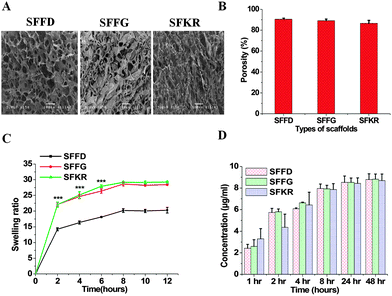
The freeze-drying method has been used in this study for the fabrication of scaffolds. In this method, pore formation is controlled during the pre-freezing process by manipulating the temperature gradients. Larger the temperature gradient, longer the duration of ice crystal formation, and thus larger the pore size.59 The freeze-dried technique in this study creates pore sizes of [100–120 μm] with interconnected porous microstructure within the matrices first by pre-freezing at −20 °C then allowing sublimation of crystals. By artificially controlling the pore formation, we are able to prepare scaffolds that are appropriate for skin repair and regeneration.60 The cross-sectional morphologies of the SFFD, SFFG and SFKR scaffolds are shown in Fig. 1A. The interconnected 3D porous structure was observed in all three scaffolds with pore sizes of 83 ± 10 μm and 81 ± 9 μm for SFFD and SFFG respectively, and 110 ± 12 μm for SFKR scaffolds.Porosity measurement of scaffolds was done by the liquid displacement method using hexane as the displacing liquid. Hexane was chosen because it permeates into scaffolds without causing shrinkage or swelling compared to other organic solvents including ethanol.34 All the scaffolds showed porosity ranging between 87 and 91% with pure SFFD scaffolds recording the highest as shown in Fig. 1B. Porosity did not vary significantly among different types of scaffolds (p > 0.05).
For skin repair and regeneration, higher porosity and 3D porous structure is a prerequisite in tissue-engineered matrices as it significantly influences cellular activity.61 The porous structure of the matrices determines the rate of cell proliferation and migration allowing sufficient nutrient and oxygen transport needed for wound healing.62 For this very purpose, the variation in pore sizes greatly affects cell behavior.63 Too small pores restrict cell migration and reduce the diffusion of nutrients and waste products, whereas too large pores lack specific surface area and hinders the initial cell attachment.64 The average pore sizes (100–120 μm) and porosity (>85%) of SFKR blended matrices are appropriate for fibroblasts growth and proliferation in skin defects (Fig. 1A and B). The pore size of blended scaffolds changed with addition of KR as compared to the pure SF scaffolds.
Furthermore, we tested the swelling ability of the scaffolds. The swelling ratios of various scaffolds are shown in Fig. 1C. The swelling ability of the SFKR blended and SFFG scaffolds was approximately 1.5 times that of the SFFD scaffolds (p < 0.001). The swelling equilibrium was obtained after eight hours for all scaffolds.
In order to utilize blended matrices successfully in skin tissue engineering, the integral stability of the 3D structure becomes an important criterion. Leach out rates of polymers, if any, have been measured to better evaluate this property. In vitro protein release from SFFD, SFFG and SFKR scaffolds was estimated using Bradford's reagent (Fig. 1D) until equilibrium, i.e., 48 hours. All three scaffolds showed a similar trend in protein release without any significant differences (p > 0.05). Maximum leaching was observed by 24 hours of incubation and after that there was no further change in the optical density. The leached out proteins are attributed to free SF and KR molecules, which remained unblended in the overall complex. In addition, when compared to the total protein deposited in the fabrication of the constructs, the leached-out fraction was less than 1.5% of the total scaffold mass (estimated from standard curves), suggesting significant retention of bulk protein within the blended scaffolds.
The thermal properties of the pure SF and SFKR blended scaffolds were determined by differential scanning calorimetry (DSC) and thermo gravimetric analysis (TGA) (Fig. 2A and B). DSC results of SFFD and SFFG scaffolds showed a first peak at ∼80 °C and second peaks at 272 °C and 275 °C, respectively. In contrast, SFKR scaffolds showed a first peak at 91 °C and a second peak at 285 °C (Fig. 2A). TGA analyses of the scaffolds are depicted in Fig. 2B. In SFFD and SFFG scaffolds, the first weight loss was found at around 118–121 °C and the second weight loss at around 270–272 °C. In SFKR scaffolds, the first weight loss peak was also observed at around 118–121 °C but the second weight loss peak was observed at 285 °C.
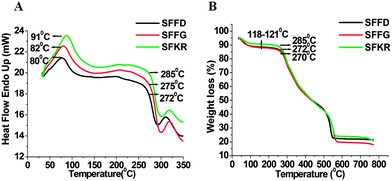 | ||
| Fig. 2 (A and B) Differential scanning calorimetry (DSC) and thermogravimetric analysis (TGA) of pure SF and SFKR blended 3D scaffolds. | ||
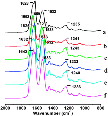
Fig. 3 shows FTIR spectra of pure SF and SFKR blended scaffolds. Infrared absorption spectra of SFFD, SFFG and SFKR show characteristic absorption peaks assigned to the peptide bonds (–CONH–) that give rise to amide I, amide II, and amide III signature peaks. Amide I is useful for the analysis of the secondary structure of proteins and is mainly related with the C![[double bond, length as m-dash]](https://www.rsc.org/images/entities/char_e001.gif) O stretching, appearing within the range of 1600–1700 cm−1. Amide II, which falls in the range of 1520–1540 cm−1, is related to N–H bending. Amide III is in the range of 1220–1300 cm−1, and it results from in-phase combination of C–N stretching and C
O stretching, appearing within the range of 1600–1700 cm−1. Amide II, which falls in the range of 1520–1540 cm−1, is related to N–H bending. Amide III is in the range of 1220–1300 cm−1, and it results from in-phase combination of C–N stretching and C![[double bond, length as m-dash]](https://www.rsc.org/images/entities/char_e001.gif) O bending vibration.55 Untreated SFKR scaffolds showed amide I, amide II and amide III bands at 1628 cm−1, 1532 cm−1 and 1235 cm−1 whereas untreated and regenerated SFFD and SFFG scaffolds showed the characteristic peaks of amide I, amide II and amide III bands at 1659 cm−1, 1538 cm−1, 1241 cm−1 and 1652 cm−1, 1541 cm−1, 1243 cm−1, respectively. After ethanol treatment, FTIR spectra of all three scaffolds showed a shift in the amide I band from 1628 to 1625 cm−1, 1659 to 1632 cm−1, 1652 to 1642 cm−1 for SFKR, SFFD, and SFFG respectively.
O bending vibration.55 Untreated SFKR scaffolds showed amide I, amide II and amide III bands at 1628 cm−1, 1532 cm−1 and 1235 cm−1 whereas untreated and regenerated SFFD and SFFG scaffolds showed the characteristic peaks of amide I, amide II and amide III bands at 1659 cm−1, 1538 cm−1, 1241 cm−1 and 1652 cm−1, 1541 cm−1, 1243 cm−1, respectively. After ethanol treatment, FTIR spectra of all three scaffolds showed a shift in the amide I band from 1628 to 1625 cm−1, 1659 to 1632 cm−1, 1652 to 1642 cm−1 for SFKR, SFFD, and SFFG respectively.
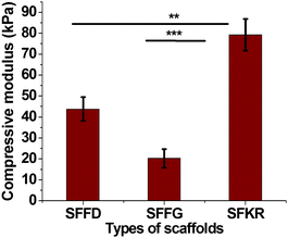
To evaluate the mechanical properties of the scaffolds, which are quite important for the clinical applications, the compressive properties of the different scaffolds are compared in Fig. 4. The SFFG scaffolds were soft and showed minimal compressive strength when compared to SFFD scaffolds. In this experiment, scaffolds were compressed to 80% to evaluate the compressive strength of each structure. As a result, SFKR had highest resistance to compression (∼80 kPa) followed by SFFD (43 kPa) then SFFG (21 kPa) scaffolds. SFKR blended scaffolds showed 2-fold significant increase in compressive modulus as compared to SFFD or SFFG (p < 0.001 and p < 0.01 respectively).
In vitro degradation
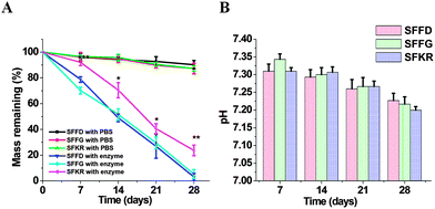
The biodegradation results are shown in Fig. 5A and B. Pure SF scaffolds incubated in protease had the highest weight reduction recorded over 90% degradation in 28 days. The degradation of SFKR in protease solution was significantly slower, with ∼30% weight remaining. Controls for each scaffold were kept in PBS (pH 7.4) without enzyme and showed negligible (≤10%) mass loss. The pH of the resulting degradation medium was determined over regular intervals and was found to be in the range of 7.2–7.4 after 28 days of incubation (Fig. 5B). These results show that the degradation of the composite scaffold was slower compared to the pure SF scaffolds and that there was no release of acidic by-products.Cell attachment and proliferation on 3D scaffolds
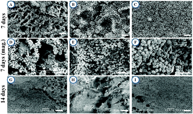
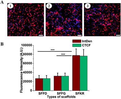
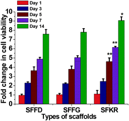
Cell growth and attachment on different scaffolds was observed after 7 and 14 days of culture. Cell attachments were successful on all three scaffolds showing clusters distributed throughout the scaffold (Fig. 6). Cells were round or spindle shaped in morphology after 7 days of culture and more prominent attachment was seen in SFKR scaffolds as compared to the pure SF scaffolds. At maximum confluency, approximately after 14 days of culture, pure SF scaffolds showed sparse or less attachment of cells when compared to SFKR. Furthermore, cell attachment and proliferation on the scaffolds was evaluated using fluorescence microscopy as shown in Fig. 7. All three types of scaffolds showed good cell attachment after two weeks of culture in DMEM/F-12 media supplemented with 10% FBS. SFKR scaffolds showed more cell attachment and proliferation evident from increased development of actin filaments in these 3D scaffolds (Fig. 7B). These findings were similar to the SEM observations as shown in Fig. 6.Cell viability and proliferation are indicative of the cellular compatibility and appropriateness of a scaffold for tissue engineering applications. In order to better assess cell viability and cytocompatibility of scaffolds, quantified analyses at regular intervals using MTT assay had been administered. All three scaffolds exhibited good cell viability for the 14 days of culture.
Murine skin fibroblasts growth and viability was observed to increase with the progression of time from samplings after 1, 3, 5, 7 and 14 days of culture, indicating that the scaffolds were able to support fibroblast proliferation without toxicity. Across the three different scaffolds, no significant differences (p > 0.05) were notable in cell viability in the first 3 days of culture. On the fifth day, however, the SFKR scaffold started to show significantly higher cell viability (p < 0.05) compared to other pure SF scaffolds and continued to outgrow the others for the remaining days of cell culture (Fig. 8).
Localization of Col I within the tissue construct
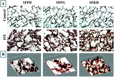
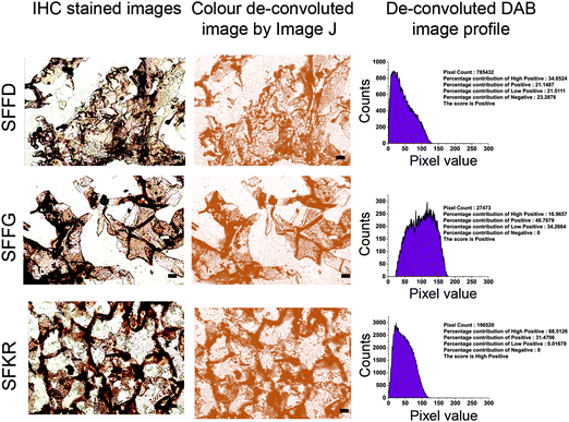
IHC analysis for localization of Col I showed positive staining for all three scaffolds but with differences in the deposition and distribution behavior depending on the composition of scaffolds (Fig. 9A).SFKR blended scaffolds showed uniformly distributed staining compared to the pure SF scaffolds. The immunostained images of SFKR constructs consisted primarily of individual or a few cells surrounded by ECM, interspersed between short fragments of scaffolds (Fig. 9A). Pure SF constructs showed relatively less amounts of ECM when compared to SFKR. There was less or minimum staining for Col I in non-seeded scaffolds. The 3D representation of IHC stain localization to expressed and deposited Col I has been shown in Fig. 9B. Further data analysis of high magnification immunostained images was done using color de-convoluted plugin of the ImageJ software. This analysis showed the histogram profile of pixel against the intensity of staining in IHC images and score (Fig. 10). This method of scoring returned “high positive” for SFKR scaffolds and “positive” for other SF scaffolds.
Discussion
The development of dermal substitutes plays an important role for the treatment of full thickness skin defects including both acute and chronic wounds.24,29 Herein, we have utilized a blend of natural polymers, SF and KR, to extract maximum benefits derived from their native form while at the same time to enhance the shortcomings of each standalone products. Additionally, we have also employed freeze-dried and freeze-gelled pure SF 3D scaffolds as controls.As mentioned above, pore size, porosity, and swelling ability of matrices are predetermining factors of scaffold functions in skin repair and regeneration. The swelling ability of the porous 3D scaffolds depends mainly on the 3D network structure of matrices and hydrophilicity.28,65,66 Ideally in pure silk-based scaffolds, the porous structure compensates for the hydrophobicity and thus the functions are evidently dependent on the pore size. Optimizing pore sizes has become an important process in the production of these scaffolds. Small pore sizes lead to reduced porosity and insufficient swelling causing inhibition of nutrient transferal, whereas, larger pore sizes hinder cell attachment compromising overall cell viability leading to excess swelling and structural deformation. Controlling the pore size is critical for optimal swelling propensity, which is a must for maximum nutrient allocation without compromising overall structural integrity. Furthermore, this attribute ultimately controls cell attachment, migration, and tissue regeneration.67 SFKR and SFFG reported a 1.5 fold increased swelling ability than SFFD. The higher swelling ability of the SFKR demonstrates the compensatory effects of biomaterial blending, which in this case, KR's hydrophilicity had drastically improved the swelling ability of the overall structure. Meanwhile, the increase in the swelling ability of the SFFG scaffold is a by-product from its unique fabrication method as the gelation process itself enhanced the water retention of the structure to overcome its functional limitation. Generally, pure SF scaffolds, as in the case of SFFD scaffolds, are considered unsuitable for dermal substitutions because of their low hydrophilicity and relatively small pore sizes.29 On the other hand, the 3D porous SFKR scaffold demonstrates high porosity and swelling ratios furnishing a good microenvironment for cellular communication and growth, and thus, proves to be functionally competent for delivering a platform for dermal reconstruction.
Blended systems, much like the SFKR scaffolds, have attracted much interest in tissue engineering applications as they possess infinite potentials with improved physico-chemical, degradable, mechanical, and biocompatible properties.2,27,29,50,68
FTIR data had been analyzed on the available scaffolds in order to better understand the superior characteristics of the blended complexes through comparison studies of their detailed structures. FTIR results on SFFD and SFFG suggested a strong presence of random coils and α-helix conformations, further to be referred to as the silk-I structure, whereas the amide I peak in the SFKR data indicated β-sheet conformations in place of the α-helices, further to be referred to as the silk-II structure. All scaffolds showed a shift in the amide I peak after ethanol treatment (Fig. 3) indicating a transition of conformation from silk-I structure to silk-II structure. The stable silk-II conformations are further reinforced through the compact structure of the SFKR scaffold with the many ionic interactions between functional groups of SF and KR. The stability enhances the thermal and mechanical properties of the structure as revealed from the compressive modulus experiments and DSC and TGA analyses (Fig. 2 and 4). Additionally, the SFKR scaffolds exhibited significantly less (≤1.5%) leaching of proteins and improved degradability (Fig. 1D and 5). All evidence demonstrate that the basic structure of the SFKR blended scaffold is the fundamental basis of the many advantages displayed when compared to pure SF scaffolds. The mechanical and physico-chemical advantages gained from the stable structure are crucial for skin tissue engineering applications and further have potential in future research and development.
Besides the functional and structural parameters, biocompatibility to support cell viability and proliferation is a priority in choosing the proper dermal substitute. The distribution of cells over the matrix is mainly influenced by the scaffold design, morphology, and chemical composition,37 and both SF and KR have been reported to fit this profile with enhanced wound healing potential.29,45,46,49,51,52,54 SFKR scaffolds with 10% KR had been observed through SEM. Cell growth, cell attachment, and proliferation were indeed more prominent when compared to other pure SF scaffolds (Fig. 6–8). It is assumed that the abundance in natural RGD and LDV integrin binding sequences endorsed a strong cell to matrix attachment. This result was in agreement with earlier studies reporting stimulatory effects of KR in fibroblast adhesion and growth.49,52
Wound healing is a complex process which includes highly integrated and programmed phases: hemostasis, inflammation, proliferation, neovascularization, collagen deposition, tissue remodeling, epithelialization, and wound contraction.69 The principal cellular component of skin responsible for dermal homeostasis and repair is the fibroblast. Fibroblasts provide a suitable support framework to new blood vessel growth and also facilitate epithelialization by controlling collagen synthesis and deposition.70,71 The ECM of most tissues, including the dermis, contains collagen, and types I, III, IV and V partake in the wound healing process. In particular, Col I is crucial for cell growth, adhesion, migration, and differentiation and also promotes keratinocyte migration. Therefore, expression of Col I is an important indicator of fibroblast function. In this study, IHC staining of the constructs (Fig. 9) was able to identify the uniform expression of Col I in SFKR compared to the pure SF scaffolds, and ImageJ analysis further confirmed the obvious difference between the constructs (Fig. 10). The correlation of Col I expression and cell viability can also be observed through many of the evidences provided in this study. Fluorescence microscopy results, as well as the SEM results, visually demonstrate the superb cell viability in SFKR blends, and the quantification data from the MTT assay after the fifth day of cell culturing confirm such findings. We could easily gather that the difference in cell viability would be due to several factors along with the Col I expression among the many.
The in vitro 3D reconstructed skin models have expressed essential structural and functional components of native skin including ECM proteins and factors which promotes cellular differentiation in vivo.72 Collagen is an important component for cell proliferations and tissue formation which solely depends on fibroblasts.73 Therefore, in skin wound healing promotion, detecting the collagen secreted content is a key index. Since the SFKR blended scaffold based on an in vitro skin model with enhanced biostability and good biocompatibility has demonstrated the ability to promote collagen secretion, it is potentially a good biomaterial for wound healing and skin regeneration. Silk fibroin based-biomaterials have been used in wound healing and skin regeneration studies with promising results;27,41–43,45 nevertheless, the present study exploits for the first time the combination of silk fibroin and human hair keratin for the production of wound dressing scaffolds and an alternative biomaterial for dermal reconstruction.
Conclusions
This study describes the successful fabrication, characterization, and evaluation of dermal skin substitute of SFKR blended 3D scaffolds for skin tissue engineering. Structurally, SFKR scaffolds showed stable 3D interconnected pores with high porosity and swelling ability, all while maintaining the rigidity of the overall complex. The physico-chemical, thermal, mechanical, and degradable properties have been enhanced in comparison to the pure SF scaffolds making it appropriate for effective wound healing. Furthermore, these composite scaffolds supported the basic needs for fibroblast growth, attachment, and proliferation along with intact ECM deposition, specifically, for Col I. These findings demonstrate that SFKR blended scaffolds are promising substrates for dermal reconstruction, wound healing, and other biomedical applications. For future studies, we suggest that the SFKR scaffolds be used for future skin tissue engineering investigations possibly for dermo-epidermal or in co-culture studies with different types of cells such as epidermal stem cells and keratinocytes.Acknowledgements
This work was supported by the National Research Foundation (NRF-NRFF2011-01) and (NRF-CRP10-2012-07), the National Medical Research Council (NMRC/CBRG/0005/2012).Notes and references
- S. Zhong, Y. Zhang and C. Lim, Wiley Interdiscip. Rev.: Nanomed. Nanobiotechnol., 2010, 2, 510–525 CrossRef CAS PubMed.
- Y. Liu, L. Ma and C. Gao, Mater. Sci. Eng., C, 2012, 32, 2361–2366 CrossRef CAS PubMed.
- E. Bellas, M. Seiberg, J. Garlick and D. L. Kaplan, Macromol. Biosci., 2012, 12, 1627–1636 CrossRef CAS PubMed.
- A. D. Metcalfe and M. W. Ferguson, Biomaterials, 2007, 28, 5100–5113 CrossRef CAS PubMed.
- W. Choi, R. Wolber, W. Gerwat, T. Mann, J. Batzer, C. Smuda, H. Liu, L. Kolbe and V. J. Hearing, J. Cell Sci., 2010, 123, 3102–3111 CrossRef CAS PubMed.
- F. Groeber, M. Holeiter, M. Hampel, S. Hinderer and K. Schenke-Layland, Adv. Drug Delivery Rev., 2011, 63, 352–366 CrossRef CAS PubMed.
- H.-M. Wang, Y.-T. Chou, Z.-H. Wen, Z.-R. Wang, C.-H. Chen and M.-L. Ho, PLoS One, 2013, 8, e56330 CAS.
- L. Ma, C. Gao, Z. Mao, J. Zhou, J. Shen, X. Hu and C. Han, Biomaterials, 2003, 24, 4833–4841 CrossRef CAS.
- J. Schulz III, R. Tompkins and J. Burke, Annu. Rev. Med., 2000, 51, 231–244 CrossRef PubMed.
- D. Q. Nguyen, T. S. Potokar and P. Price, Burns, 2010, 36, 23–28 CrossRef PubMed.
- D. Stiefel, C. Schiestl and M. Meuli, Burns, 2010, 36, 114–120 CrossRef PubMed.
- M. Carlson, K. Faria, Y. Shamis, J. Leman, V. Ronfard and J. Garlick, Tissue Eng., Part A, 2010, 17, 487–493 CrossRef PubMed.
- W. T. Seet, M. Maaroof, K. Khairul Anuar, K.-H. Chua and A. W. Ahmad Irfan, et al. , PLoS One, 2012, 7, e40978 CAS.
- G. G. Gauglitz, S. Zedler, F. v. Spiegel, J. Fuhr, G. H. v. Donnersmarck and E. Faist, PLoS One, 2012, 7, e29942 CAS.
- K. W. Ng, D. W. Hutmacher, J.-T. Schantz, C. S. Ng, H.-P. Too, T. C. Lim, T. T. Phan and S. H. Teoh, Tissue Eng., 2001, 7, 441–455 CrossRef CAS PubMed.
- K. W. Ng, W. Tham, T. C. Lim and D. Werner Hutmacher, J. Biomed. Mater. Res., Part A, 2005, 75, 425–438 CrossRef PubMed.
- S. Böttcher-Haberzeth, T. Biedermann and E. Reichmann, Burns, 2010, 36, 450–460 CrossRef PubMed.
- S. MacNeil, Nature, 2007, 445, 874–880 CrossRef CAS PubMed.
- S. G. Priya, H. Jungvid and A. Kumar, Tissue Eng., Part B, 2008, 14, 105–118 CrossRef CAS PubMed.
- R. V. Shevchenko, M. Eeman, B. Rowshanravan, I. U. Allan, I. N. Savina, M. Illsley, M. Salmon, S. L. James, S. V. Mikhalovsky and S. E. James, Acta Biomater., 2014, 10, 3156–3166 CrossRef CAS PubMed.
- M. Kremer, E. Lang and A. Berger, Br. J. Plast. Surg., 2000, 53, 459–465 CrossRef CAS PubMed.
- H. A. Navsaria, N. O. Ojeh, N. Moiemen, M. A. Griffiths and J. D. Frame, Plast. Reconstr. Surg., 2004, 113, 978–981 CrossRef.
- L. R. M. Souto, J. Rehder, J. Vassallo, M. L. Cintra, M. H. S. Kraemer and M. B. Puzzi, Sao Paulo Med. J., 2006, 124, 71–76 CrossRef PubMed.
- V. C. van der Veen, M. van der Wal, M. C. van Leeuwen, M. M. Ulrich and E. Middelkoop, Burns, 2010, 36, 305–321 CrossRef PubMed.
- M. Lutolf and J. Hubbell, Nat. Biotechnol., 2005, 23, 47–55 CrossRef CAS PubMed.
- K. W. Ng and D. W. Hutmacher, Biomaterials, 2006, 27, 4591–4598 CrossRef CAS PubMed.
- A. Vasconcelos, A. C. Gomes and A. Cavaco-Paulo, Acta Biomater., 2012, 8, 3049–3060 CrossRef CAS PubMed.
- L. P. Yan, Y. J. Wang, L. Ren, G. Wu, S. G. Caridade, J. B. Fan, L. Y. Wang, P. H. Ji, J. M. Oliveira and J. T. Oliveira, J. Biomed. Mater. Res., Part A, 2010, 95, 465–475 CrossRef PubMed.
- S. Yan, Q. Zhang, J. Wang, Y. Liu, S. Lu, M. Li and D. L. Kaplan, Acta Biomater., 2013, 9, 6771–6782 CrossRef CAS PubMed.
- L. Meinel, R. Fajardo, S. Hofmann, R. Langer, J. Chen, B. Snyder, G. Vunjak-Novakovic and D. Kaplan, Bone, 2005, 37, 688–698 CrossRef CAS PubMed.
- Q. Zhang, S. Yan and M. Li, Materials, 2009, 2, 2276–2295 CrossRef CAS PubMed.
- L. Uebersax, H. P. Merkle and L. Meinel, J. Controlled Release, 2008, 127, 12–21 CrossRef CAS PubMed.
- G. Guan, L. Bai, B. Zuo, M. Li, Z. Wu, Y. Li and L. Wang, Bio-Med. Mater. Eng., 2010, 20, 295–308 CAS.
- N. Bhardwaj and S. C. Kundu, Carbohydr. Polym., 2011, 85, 325–333 CrossRef CAS PubMed.
- N. Bhardwaj, Q. T. Nguyen, A. C. Chen, D. L. Kaplan, R. L. Sah and S. C. Kundu, Biomaterials, 2011, 32, 5773–5781 CrossRef CAS PubMed.
- N. Bhardwaj, S. Chakraborty and S. C. Kundu, Int. J. Biol. Macromol., 2011, 49, 260–267 CrossRef CAS PubMed.
- N. Bhardwaj and S. C. Kundu, Biomaterials, 2012, 33, 2848–2857 CrossRef CAS PubMed.
- B. B. Mandal and S. C. Kundu, Macromol. Biosci., 2008, 8, 807–818 CrossRef CAS PubMed.
- B. B. Mandal, A. Grinberg, E. S. Gil, B. Panilaitis and D. L. Kaplan, Proc. Natl. Acad. Sci. U. S. A., 2012, 109, 7699–7704 CrossRef CAS PubMed.
- B. B. Mandal, E. S. Gil, B. Panilaitis and D. L. Kaplan, Macromol. Biosci., 2013, 13, 48–58 CrossRef CAS PubMed.
- A. Sugihara, K. Sugiura, H. Morita, T. Ninagawa, K. Tubouchi, R. Tobe, M. Izumiya, T. Horio, N. G. Abraham and S. Ikehara, Exp. Biol. Med., 2000, 225, 58–64 CrossRef CAS.
- S. E. Wharram, X. Zhang, D. L. Kaplan and S. P. McCarthy, Macromol. Biosci., 2010, 10, 246–257 CrossRef CAS PubMed.
- A. Schneider, X. Wang, D. Kaplan, J. Garlick and C. Egles, Acta Biomater., 2009, 5, 2570–2578 CrossRef CAS PubMed.
- S. E. Navone, L. Pascucci, M. Dossena, A. Ferri, G. Invernici, F. Acerbi, S. Cristini, G. Bedini, V. Tosetti and V. Ceserani, Stem Cell Res. Ther., 2014, 5, 7, DOI:10.1186/scrt396.
- D.-H. Roh, S.-Y. Kang, J. Y. Kim, Y.-B. Kwon, H. Y. Kweon, K. G. Lee, Y.-H. Park, R.-M. Baek, C.-Y. Heo and J. Choe, J. Mater. Sci.: Mater. Med., 2006, 17, 547–552 CrossRef CAS PubMed.
- A. Vasconcelos, A. P. Pêgo, L. Henriques, M. Lamghari and A. Cavaco-Paulo, Biomacromolecules, 2010, 11, 2213–2220 CrossRef CAS PubMed.
- J. Schweizer, P. E. Bowden, P. A. Coulombe, L. Langbein, E. B. Lane, T. M. Magin, L. Maltais, M. B. Omary, D. A. Parry and M. A. Rogers, J. Cell Biol., 2006, 174, 169–174 CrossRef CAS PubMed.
- R. Moll, M. Divo and L. Langbein, Histochem. Cell Biol., 2008, 129, 705–733 CrossRef CAS PubMed.
- J. G. Rouse and M. E. Van Dyke, Materials, 2010, 3, 999–1014 CrossRef PubMed.
- B. Srinivasan, R. Kumar, K. Shanmugam, U. T. Sivagnam, N. P. Reddy and P. K. Sehgal, J. Biomed. Mater. Res., Part B, 2010, 92, 5–12 CrossRef PubMed.
- S. Reichl, Biomaterials, 2009, 30, 6854–6866 CrossRef CAS PubMed.
- S. Wang, F. Taraballi, L. P. Tan and K. W. Ng, Cell Tissue Res., 2012, 347, 795–802 CrossRef CAS PubMed.
- F. Taraballi, S. Wang, J. Li, F. Y. Y. Lee, S. S. Venkatraman, W. R. Birch, S. H. Teoh, F. Y. C. Boey and K. W. Ng, Adv. Healthcare Mater., 2012, 1, 513–519 CrossRef CAS PubMed.
- W. T. Sow, Y. S. Lui and K. W. Ng, Nanomedicine, 2013, 8, 531–541 CrossRef CAS PubMed.
- A. Vasconcelos, G. Freddi and A. Cavaco-Paulo, Biomacromolecules, 2009, 10, 1019 CrossRef CAS PubMed.
- M. Zoccola, A. Aluigi, C. Vineis, C. Tonin, F. Ferrero and M. G. Piacentino, Biomacromolecules, 2008, 9, 2819–2825 CrossRef CAS PubMed.
- S. Sofia, M. B. McCarthy, G. Gronowicz and D. L. Kaplan, J. Biomed. Mater. Res., 2001, 54, 139–148 CrossRef CAS.
- S. Chatterjee, R. Malhotra, F. Varghese, A. B. Bukhari, A. Patil, A. Budrukkar, V. Parmar, S. Gupta and A. De, PLoS One, 2013, 8, e54055 CAS.
- M. Li, S. Lu, Z. Wu, H. Yan, J. Mo and L. Wang, J. Appl. Polym. Sci., 2001, 79, 2185–2191 CrossRef CAS.
- G. Chen, T. Ushida and T. Tateishi, Macromol. Biosci., 2002, 2, 67–77 CrossRef CAS.
- J. Zeltinger, J. K. Sherwood, D. A. Graham, R. Müeller and L. G. Griffith, Tissue Eng., 2001, 7, 557–572 CrossRef CAS PubMed.
- B. J. Lawrence and S. V. Madihally, Cell Adh. Migr., 2008, 2, 9–16 CrossRef.
- C. M. Murphy and F. J. O'Brien, Cell Adh. Migr., 2010, 4, 377–381 CrossRef.
- I. Yannas, Clin. Mater., 1992, 9, 179–187 CrossRef CAS.
- S.-N. Park, J.-C. Park, H. O. Kim, M. J. Song and H. Suh, Biomaterials, 2002, 23, 1205–1212 CrossRef CAS.
- W. Wang, M. Zhang, W. Lu, X. Zhang, D. Ma, X. Rong, C. Yu and Y. Jin, Tissue Eng., Part C, 2009, 16, 269–279 CrossRef PubMed.
- B. Chan and K. Leong, Eur. Spine J., 2008, 17, 467–479 CrossRef PubMed.
- A. Sionkowska, Prog. Polym. Sci., 2011, 36, 1254–1276 CrossRef CAS PubMed.
- S. Guo and L. A. DiPietro, J. Dent. Res., 2010, 89, 219–229 CrossRef CAS PubMed.
- A. Gosain and L. A. DiPietro, World J. Surg., 2004, 28, 321–326 CrossRef PubMed.
- J. S. Boateng, K. H. Matthews, H. N. Stevens and G. M. Eccleston, J. Pharm. Sci., 2008, 97, 2892–2923 CrossRef CAS PubMed.
- C. A. Brohem, L. B. da Silva Cardeal, M. Tiago, M. S. Soengas, S. B. de Moraes Barros and S. S. Maria-Engler, Pigm. Cell Melanoma Res., 2011, 24, 35–50 CrossRef PubMed.
- H. Ishibuchi, M. Abe, Y. Yokoyama and O. Ishikawa, Exp. Dermatol., 2010, 19, e111–e116 CrossRef PubMed.
| This journal is © The Royal Society of Chemistry 2015 |

