 Open Access Article
Creative Commons Attribution 3.0 Unported Licence
Predicting solvent effects on the structure of porous organic molecules†
Valentina
Santolini
a,
Gareth A.
Tribello
b and
Kim E.
Jelfs
*a
aDepartment of Chemistry, Imperial College London, South Kensington, London SW7 2AZ, UK. E-mail: k.jelfs@imperial.ac.uk; Web: http://www.twitter.com/JelfsCompChem Tel: +44 (0)20759 43438
bAtomistic Simulation Centre, Department of Physics and Astronomy, Queen's University Belfast, University Road, Belfast, BT7 1NN, UK
First published on 2nd September 2015
Abstract
A computational approach for the prediction of the open, metastable, conformations of porous organic molecules in the presence of solvent is developed.
The influence of solvents on the structure and properties of biological and chemical systems is difficult both to determine and to predict. In simulations the solvent is frequently either ignored or treated as a continuous medium. However, we know that solvents can play vital roles in biology and chemistry and that tools that could predict solvent effects would have impacts in fields as diverse as materials and drug discovery. Here we develop an approach for the specific problem of predicting the voids formed within the molecular structure of porous organic molecules in solution or in the solvate solid state. Porous organic molecules are an alternative class of porous materials to extended networks such as zeolites and metal organic frameworks (MOFs). They lack chemical bonding in 3-dimensions and instead, as a result of internal cavities, have pores even in solution, which can then be assembled in the solid state.1–3 These materials have some potential advantages over porous network materials, particularly in terms of their solubility. There are processing advantages and their inherently modular nature allows for property tuning through varying the ratios of different ‘modules’.4 Examples include calixarenes, cyclodextrins, cryptophanes, cucurbiturils and ‘cages’. Together these show promise for applications in catalysis,5 sensing6,7 and separations.8,9
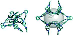
As attempts are made to synthesise new porous organic molecules, in particularly those with larger pores, an increasing problem is a lack of ‘shape persistence’. In the absence of solvent, the large number of flexible torsions allow the molecule to undergo collapse, which is often associated with the complete loss of the pore.10Fig. 1 shows an example of this for the porous organic imine cage CC8, which can be synthesised through imine condensation of tris(4-formylphenyl)amine and (R,R)-1,2-cyclohexanediamine (see Fig. S1 for all reaction schemes, ESI†).10 The collapse process is important as, if solvent is deleted in silico from a solvate crystal structure, then materials may superficially appear highly porous.11 However, this of course neglects the structural collapse or phase change these molecules will frequently undergo upon desolvation. Whilst these non-shape persistent materials might seem of little interest, they could have attractive properties in solution, such as encapsulation, separation8 or optical sensing.7 For such molecules, prediction of solvate molecular structures would allow for rational design of synthetic modifications to prevent their loss of porosity.12 This prediction thus forms an integral part of any in silico molecular design process.13 It has previously been shown that it is possible to use simulations to predict the odd–even effect of precursor alkane chain length upon the molecular mass of the resultant porous organic imine cages14 and furthermore that, if the two-dimensional chemical structure is known, the 3-dimensional crystal structure can be predicted using polymorph prediction techniques.15,16 Thus far, however, solvent effects have not been incorporated into these prediction processes despite examples where both molecular mass17 and polymorph18 have been affected by solvent choice. Prediction of structural and property changes upon solvation may also open the door to prediction of stimuli-response materials.
 | ||
| Fig. 1 A comparison of (left) low energy, voidless, conformation of CC8 and (right) higher energy structure with a void of ∼5 Å radius in grey. | ||
Successful predictions of the solvate stoichiometry and structure of pharmaceuticals have been performed, although including solvent considerably increases the computational expense of these methods.19 Furthermore, whilst these simulations involve 1 or 2 solvent molecules per ‘host’ molecule, for porous molecular systems there can be more than 70 solvent molecules per host,10 which would represent a significant challenge. For zeolitic materials, de novo design of templates to guide towards desired topologies has had some success.20,21 However, these successes have not been replicated for self-assembled systems such as MOFs and porous molecular materials. In addition, many MOFs exhibit phase changes between ‘open’ and ‘closed’ structures in response to guest-loading, temperature or pressure, the archetypal example being MIL-53.22 If the ‘open’ and ‘closed’ structures are known, then the external conditions, such as the pressure, required for the transition to occur can be predicted through a thermodynamic framework.23 Issues with MOF stability with respect to structural collapse are well known and, if forcefields are available, the lack of structural stability can be predicted using atomistic simulations that start from an initially ‘open’ phase.24 Predicting the structures of ‘open’ phases that form in response to guest loading is, by contrast, more difficult.25
We demonstrate that constrained molecular dynamics (MD) simulations can predict the ‘open’ form of several non-shape persistent porous organic molecules by reproducing reported solvate structures. We restrict ourselves to porous organic molecules that retain a defined cavity in the presence of guest molecules, whereby this open conformation is metastable with respect to the collapsed conformations and not significantly affected by crystal packing forces. We investigate several reported porous imine cages (Fig. S1, ESI†), including CC8,10 the endo-functionalised cage of Mastalerz and co-workers,26 the fluorescent cage of Mukherjee and co-workers7 and two hypothetical imine cage molecules; the [6+9] and [8+12] versions of the reported [4+6] CC3 molecule.27 In addition, we look at two other classes of porous organic molecules; the glycoluril-based band-like macrocycles known as cucurbiturils,28 and cryptophanes,29 formed from two interconnected cyclotriveratrylenes cups. We include the ‘parent’ cucurbituril, CB6,30 bis-nor-sec-CB10 (CB10-ns), which lacks two methylene bridges compared to CB10, resulting in two interconnected cavities rather than one,31 and cryptophane-A, where the single-crystal X-ray diffraction (SCXRD) structures of Xe and water-loaded conformations and the collapsed conformation have recently been reported.32 The underlying topology of these molecules covers a range of polyhedra, including tetrahedron, cube and triangular prism (Fig. S2, ESI†). None of these molecules retain a large cavity in their low energy structures in the absence of solvent, although the Mastalerz cage and CB6 retain a smaller void.
Conformer search algorithms can not discover the open conformations of the porous organic molecular systems, as they typically lie >100 kJ mol−1 above the low energy collapsed conformations and these high energy regions of configuration space are not adequately sampled, if at all. As detailed in the ESI† (Section 1.8), we tried a number of different methods before settling on a simple approach that involved applying an energetic penalty if any atom from the molecule was within a certain distance of the molecule's centre of mass, xc. In doing this we calculate a smoothed version of the minimum distance, s, between each atomic position, xi, and xc using:
 | (1) |
The simulations were typically started from a collapsed conformation, although the starting point was not important due to the SA procedure. The OPLS all-atom forcefield33 was used, which we have previously used for the prediction of conformer energetics of porous organic imine cages.14 All MD simulations were performed with DL_POLY2.20,34 the velocity verlet algorithm, a time step of 0.7 fs and an intermolecular cutoff of 12 Å. PLUMED235 was used to apply the constraints. During the first 14 ps of a 10 ns MD simulation, the force constant was scaled from 0 to 50![[thin space (1/6-em)]](https://www.rsc.org/images/entities/char_2009.gif) 000 kJ mol−1 nm−2. These calculations were run for a range of constraint sizes and sampled every 0.35 ps. The resulting ∼30
000 kJ mol−1 nm−2. These calculations were run for a range of constraint sizes and sampled every 0.35 ps. The resulting ∼30![[thin space (1/6-em)]](https://www.rsc.org/images/entities/char_2009.gif) 000 structures were geometry optimised using MacroModel (see ESI†). Only those with a spherical void (between 2–4 Å, dependent on the system) were retained. Duplicates were removed and whilst some inflated structures would collapse during the minimisation, typically ∼30% were found to be local open minima. Finally, SA was applied on the constraint size that gave the lowest energy conformation from the 300 K simulations. This involved 500 ps simulations at each temperature, with increments of 50 K between 300 and 500 K. This was repeated a minimum of 10 times, with structures sampled during the 300 K simulations.
000 structures were geometry optimised using MacroModel (see ESI†). Only those with a spherical void (between 2–4 Å, dependent on the system) were retained. Duplicates were removed and whilst some inflated structures would collapse during the minimisation, typically ∼30% were found to be local open minima. Finally, SA was applied on the constraint size that gave the lowest energy conformation from the 300 K simulations. This involved 500 ps simulations at each temperature, with increments of 50 K between 300 and 500 K. This was repeated a minimum of 10 times, with structures sampled during the 300 K simulations.
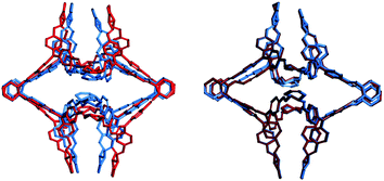
We first examine systems where we can make a comparison to the solvate crystal structures. CC8 is the largest system, with 272 non-hydrogen atoms. The low energy structure does not contain a void because it has vertices folded inwards. Experiments have thus shown that the desolvated material is non-porous.10 Constrained MD with a probe radius of 6 Å was found to give the lowest energy open conformation (Fig. S3, ESI†). This configuration had a final void size of 4.6 Å, which is smaller than the probe radius because we subtract the van der Waals radius when calculating this quantity, but not when calculating the constraint. The low energy, open conformation is >113 kJ mol−1 higher in energy than the collapsed conformation (Fig. 1) and has pseudo-octahedral symmetry. This is a good match to the experimental structure, which is also pseudo-octahedral, but not completely symmetric, presumably because of the high degree of solvation (∼70 solvent molecules per cage). The similarity index between the simulated and experimental structure, calculated via the radial distribution function of the interatomic distances of all non-hydrogen atoms, is 58%, for further details refer to Section 1.7 of the ESI.† As shown in the overlay in Fig. 2, the main difference is that the simulated structure has vertex pairs that are contracted towards each other by ∼2 Å. Interestingly, when we geometry optimise the experimental solvate conformation, we see the same contraction of the vertices (Fig. 2) and a similarity of 98% to our structure, suggesting the difference is a crystal packing effect we can not expect to account for here. Nevertheless, the prediction of conformation, shape and void size is in good agreement with experiment.
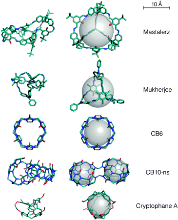
The Mastalerz imine cage has tetrahedral topology from a [6+4] reaction. We found in MD simulations that the tetrahedral symmetry was not maintained and there was a partial collapse of the void, although a smaller void of 2.1 Å radius is retained (compared to ∼5 Å in the solvate crystal structure). This partial collapse of the intrinsic pore in the absence of solvent may explain why the reported Brunauer–Emmett–Teller (BET) surface area of 1377 m2 g−1 for this system36 is so much smaller than the computed solvent accessible surface area of >4000 m2 g−1 for a N2 probe (this holds for radii of 1.55–1.82 Å, spanning the van der Waals and kinetic radius of N237). When the probe radius was set to 7 Å or below, the lowest energy open conformation was found. For larger probe radii, higher energy structures were found (Fig. S4, ESI†). The open conformation is >158 kJ mol−1 above the partially collapsed conformation and has a void radius of 5.2 Å (Fig. 3). This conformation is in good agreement with the solvate crystal structure (Fig. S5, ESI†), with a similarity index of 85% and endo-functionalisation of the alcohol groups. The very minor torsional differences could be accounted for through either crystal packing effects or minor forcefield inaccuracies.
 | ||
| Fig. 3 The minimum energy collapsed structures (left) and lowest energy open conformations (right) found here for reported systems. | ||
The Mukherjee cage is a [3+2] cage with phenyl groups pendant on each of the 3 vertices, and 2 trimethylbenzene faces. In the absence of solvent we found this amine cage to completely collapse during the MD simulations. However, we found an open, highly symmetric structure with a void radius of 3.6 Å for all probe sizes between 2–8 Å (Fig. 3). The lowest energy structure has a cage with the same core as the solvate crystal structure (Fig. S5, ESI†), but with the pendant vertices arranged more symmetrically, towards a C3 symmetry – the solvate crystal structure has the vertices arranged in a T-shape. These small differences result in a similarity index of only 89%. We expect the lower symmetry crystal structure is due to packing forces and that our more symmetric conformation would be dominant in solution, where this molecule acts as a chemical sensor for the explosive picric acid.7 These conformational changes between the collapsed, solution and solvate solid state structure undoubtedly have the potential to impact upon chemical sensing.
CB6 is known to have potential inversion of glycoluril units,38 in fact we find that every other glycoluril is inverted in the lowest energy ‘collapsed’ conformation of CB6 (Fig. 3). For constrained simulations with probes above 2.5 Å, we find exclusively the open conformation without any glycoluril inversion, which is an excellent match to the SCXRD structure (similarity 99.8%), Fig. 3 and Fig. S6 (ESI†). For CB10-ns, we find the collapsed conformation to have no internal cavity. The SCXRD solvate structure has two distinct cavities, which are not at the molecule's centre of mass. Nevertheless, if we use large probe sizes (16 Å), we exclusively find the open conformations to have the reported dual symmetrical interconnected cavities, Fig. 3 and Fig. S6 (ESI†). The similarity is 93%, but as with CC8, this increases to 99.7% if we compare our conformation to the geometry optimised SCXRD structure. Cryptophane-A is the only system studied here where a collapsed SCXRD structure has been reported.32 Our constrained calculations correctly predict the open anti conformation of cyclotriveratrylenes (Fig. 3 and Fig. S6, ESI†). We also found different probe sizes can match to the Xe-loaded or water-loaded SCXRD structures, which vary in cavity size, with matches of 94% (Xe) and 91% (water), which increase upon geometry optimisation (96% and 96%, respectively). The change in cavity size upon loading with different guests32 is understandable given we found conformations with a range of spherical cavities (radius 2.0–2.5 Å).
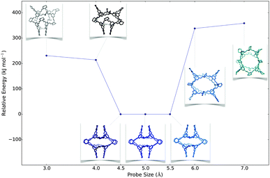
Following success with the observed molecules, we looked at two hypothetical imine cages. These are formed from the same chemistry as the reported tetrahedral [4+6] CC3 cage, but they have cubic, [8+12], and trigonal prismatic, [6+9], topologies. For [8+12] we found different structures with different probe sizes (Fig. 4 and Fig. S7, ESI†). Smaller probes gave energetically unfavourable partially collapsed structures, while larger probes gave ‘overinflated’ high energy conformations. Between 4.5–5.5 Å, we found low energy open conformations, with pseudo-octahedral symmetries that were similar in shape to the CC8 molecule. The [6+9] molecule had the potential to adopt a triangular prism shape, so we first used a cylindrical rather than a spherical probe, but found this was not necessary to find prismatic structures (Fig. S7 and S8, ESI†). We consistently found that very large spherical probes (>9 Å) gave highly overinflated structures, but that they can subsequently minimise to symmetric open conformations that lack spherical cavities, albeit with poor sampling.
 | ||
| Fig. 4 A plot of the lowest energy conformation found for each constraint size for CC3 [8+12], with the conformations shown as insets. | ||
In conclusion, we have developed an approach through which the open, metastable, conformations of porous molecules in solution or the solvate solid state can be predicted. The approach is guided through the determination of the lowest energy structure and thus requires no experimental input. Alternative shape probes can also allow for the opening of different geometry pore systems. The method has the potential to be used more broadly in the prediction of guest responsive materials, in particular for porous materials such as MOFs. For porous organic molecules our results demonstrate that the solvent is acting chiefly as a ‘scaffold’, whose effects can be reproduced without any specific chemical interactions. The prediction of the open molecular conformations is a step towards predicting the properties of these systems in solution, for example the chemical sensing of the Mukherjee cage. This capability is also a significant development for the in silico design of these materials, as successful prediction of the reaction outcome is possible through knowledge of the solution structures.
We acknowledge a Royal Society University Research Fellowship (K.E.J.), the ERC (ERC-ADG-2012-321156-ROBOT) and ARCHER time through the EPSRC Materials Chemistry Consortium (EP/L000202).
References
- G. Zhang and M. Mastalerz, Chem. Soc. Rev., 2014, 43, 1934 RSC.
- J. R. Holst, A. Trewin and A. I. Cooper, Nat. Chem., 2010, 2, 915 CrossRef CAS PubMed.
- W. R. Saenger, J. Jacob, K. Gessler, T. Steiner, D. Hoffmann, H. Sanbe, K. Koizumi, S. M. Smith and T. Takaha, Chem. Rev., 1998, 98, 1787 CrossRef CAS PubMed.
- A. I. Cooper, Angew. Chem., Int. Ed., 2011, 50, 996 CrossRef CAS PubMed.
- T.-C. Lee, E. Kalenius, A. I. Lazar, K. I. Assaf, N. Kuhnert, C. H. Grün, J. Jänis, O. A. Scherman and W. M. Nau, Nat. Chem., 2013, 5, 376 CrossRef CAS PubMed.
- M. Brutschy, M. W. Schneider, M. Mastalerz and S. R. Waldvogel, Adv. Mater., 2012, 24, 6049 CrossRef CAS PubMed.
- K. Acharyya and P. S. Mukherjee, Chem. Commun., 2014, 50, 15788 RSC.
- T. Mitra, K. E. Jelfs, M. Schmidtmann, A. Ahmed, S. Y. Chong, D. J. Adams and A. I. Cooper, Nat. Chem., 2013, 5, 276 CrossRef CAS PubMed.
- L. Chen, P. S. Reiss, S. Y. Chong, D. Holden, K. E. Jelfs, T. Hasell, M. A. Little, A. Kewley, M. E. Briggs, A. Stephenson, K. M. Thomas, J. A. Armstrong, J. Bell, J. Busto, R. Noel, J. Liu, D. M. Strachan, P. K. Thallapally and A. I. Cooper, Nat. Mater., 2014, 13, 954 CrossRef CAS PubMed.
- K. E. Jelfs, X. Wu, M. Schmidtmann, J. T. A. Jones, J. E. Warren, D. J. Adams and A. I. Cooper, Angew. Chem., Int. Ed., 2011, 50, 10653 CrossRef CAS PubMed.
- L. Barbour, Chem. Commun., 2006, 1163 RSC.
- M. Liu, M. A. Little, K. E. Jelfs, J. T. A. Jones, M. Schmidtmann, S. Y. Chong, T. Hasell and A. I. Cooper, J. Am. Chem. Soc., 2014, 136, 7583 CrossRef CAS PubMed.
- K. E. Jelfs and A. I. Cooper, Curr. Opin. Solid State Mater. Sci., 2013, 17, 19 CrossRef CAS PubMed.
- K. E. Jelfs, E. Eden, J. L. Culshaw, S. Shakespeare, E. O. Pyzer-Knapp, H. P. G. Thompson, J. Bacsa, G. M. Day, D. J. Adams and A. I. Cooper, J. Am. Chem. Soc., 2013, 135, 9307 CrossRef CAS PubMed.
- J. T. A. Jones, T. Hasell, X. Wu, J. Bacsa, K. E. Jelfs, M. Schmidtmann, S. Y. Chong, D. J. Adams, A. Trewin, F. Schiffman, F. Cora, B. Slater, A. Steiner, G. M. Day and A. I. Cooper, Nature, 2011, 474, 367 CrossRef CAS PubMed.
- E. O. Pyzer-Knapp, H. P. G. Thompson, F. Schiffmann, K. E. Jelfs, A. I. Cooper and G. M. Day, Chem. Sci., 2014, 5, 2235 RSC.
- X. Liu and R. Warmuth, J. Am. Chem. Soc., 2006, 128, 14120 CrossRef CAS PubMed.
- M. A. Little, S. Y. Chong, M. Schmidtmann, T. Hasell and A. I. Cooper, Chem. Commun., 2014, 50, 9465 RSC.
- A. J. Cruz-Cabeza, S. Karki, L. Fábián, T. Frišiić, G. M. Day and W. Jones, Chem. Commun., 2010, 46, 2224 RSC.
- D. Lewis, D. Willock, R. Catlow, J. Thomas and G. Hutchings, Nature, 1996, 382, 604 CrossRef CAS PubMed.
- R. Pophale, F. Daeyaert and M. W. Deem, J. Mater. Chem. A, 2013, 1, 6750 CAS.
- Y. Liu, J.-H. Her, A. Dailly, A. J. Ramirez-Cuesta, D. A. Neumann and C. M. Brown, J. Am. Chem. Soc., 2008, 130, 11813 CrossRef CAS PubMed.
- F.-X. Coudert, C. Mellot-Draznieks, A. H. Fuchs and A. Boutin, J. Am. Chem. Soc., 2009, 131, 3442 CrossRef CAS PubMed.
- L. Bouëssel du Bourg, A. U. Ortiz, A. Boutin and F.-X. Coudert, APL Mater., 2014, 2, 124110 CrossRef PubMed.
- L. Chen, J. P. S. Mowat, D. Fairen-Jimenez, C. A. Morrison, S. P. Thompson, P. A. Wright and T. Düren, J. Am. Chem. Soc., 2013, 135, 15763 CrossRef CAS PubMed.
- M. Mastalerz, Chem. Commun., 2008, 4756 RSC.
- T. Tozawa, J. T. A. Jones, S. I. Swamy, S. Jiang, D. J. Adams, S. Shakespeare, D. Bradshaw, T. Hasell, S. Y. Chong, C. Tang, S. Thompson, J. Parker, A. Trewin, J. Bacsa, A. M. Z. Slawin, A. Steiner and A. I. Cooper, Nat. Mater., 2009, 8, 973 CrossRef CAS PubMed.
- K. I. Assaf and W. M. Nau, Chem. Soc. Rev., 2015, 44, 394 RSC.
- T. Brotin and J. P. Dutasta, Chem. Rev., 2008, 109, 88 CrossRef PubMed.
- R. Behrend, E. Meyer and F. Rusche, Justus Liebigs Ann. Chem., 1905, 339, 1 CrossRef PubMed.
- W. H. Huang, S. M. Liu, P. Y. Zavalij and L. Isaacs, J. Am. Chem. Soc., 2006, 128, 14744 CrossRef CAS PubMed.
- O. Taratula, O. Taratula, P. A. Hill, P. A. Hill, N. S. Khan, N. S. Khan, P. J. Carroll, I. J. Dmochowski and I. J. Dmochowski, Nat. Commun., 2010, 1, 148 CrossRef PubMed.
- W. Jorgensen, D. Maxwell and J. Tirado-Rives, J. Am. Chem. Soc., 1996, 118, 11225 CrossRef CAS.
- W. Smith, C. W. Yong and P. M. Rodger, Mol. Simul., 2002, 28, 385 CrossRef CAS PubMed.
- G. A. Tribello, M. Bonomi, D. Branduardi, C. Camilloni and G. Bussi, Comput. Phys. Commun., 2013, 185, 604 CrossRef PubMed.
- M. Mastalerz, M. W. Schneider, I. M. Oppel and O. Presly, Angew. Chem., Int. Ed., 2011, 50, 1046–1051 CrossRef CAS PubMed.
- L. M. Robeson, J. Membr. Sci., 1991, 62, 165 CrossRef CAS.
- L. Isaacs, S. K. Park, S. M. Liu, Y. H. Ko, N. Selvapalam, Y. Kim, H. Kim, P. Y. Zavalij, G. H. Kim, H. S. Lee and K. Kim, J. Am. Chem. Soc., 2005, 127, 18000 CrossRef CAS PubMed.
Footnote |
| † Electronic supplementary information (ESI) available: Additional computational details, results, figures and structure files. See DOI: 10.1039/c5cc05344g |
| This journal is © The Royal Society of Chemistry 2015 |


