Magnetically separable reduced graphene oxide/iron oxide nanocomposite materials for environmental remediation
Received
22nd June 2014
, Accepted 2nd August 2014
First published on 4th August 2014
Abstract
Magnetically separable reduced graphene oxide/iron oxide (rGO/Fe3O4) nanocomposite materials were synthesized at room temperature through a facile, eco-friendly and cost-effective approach. The prepared nanocomposite materials were characterized by different techniques. X-ray diffraction analysis revealed the formation of the rGO/Fe3O4 nanocomposites, while transmission electron microscope images showed that the Fe3O4 nanoparticles with an average size of 10 nm were embedded uniformly on the surface of rGO sheets. The synthesized rGO/Fe3O4 nanocomposite materials were found to be super-paramagnetic in nature at room temperature. The photocatalytic performance of the rGO/Fe3O4 nanocomposite materials was investigated under natural sunlight irradiation using methylene blue (MB) as a model target organic pollutant. The rGO/Fe3O4 showed better adsorption behaviour and excellent photocatalytic activity towards the degradation of MB, when compared to other samples such as rGO and pristine Fe3O4 nanoparticles. This enhanced photocatalytic activity could be attributed to the synergistic effect that arises between the rGO and Fe3O4, which significantly reduces charge recombination. Moreover, the rGO/Fe3O4 nanocomposite materials exhibited good sustainability, which was evidenced by their consistent photocatalytic performance and the absence of any observable changes in morphology, even after eight cycles of operation during photocatalytic experiments. The overall results of the study indicate that these newly prepared photocatalytically stable and magnetically separable rGO/Fe3O4 nanocomposites could be potentially utilized for many environmental remediation applications.
1. Introduction
The requirement for fresh water is paramount for all living organisms, including human beings, and its availability is a major problem throughout the world at present. In the future, this issue will become even more pressing, owing to rapid industrialization and population growth. In particular, the rapid growth of the textile and dying industries has caused critical environmental problems, as some of the dye effluents from these industries can pollute ground water resources, and their utilisation has many toxic and harmful effects on human beings. In this respect, different types of photocatalytic materials viz. free-standing photocatalysts, doped photocatalysts, dual semiconductors and noble metal deposited photocatalysts have been developed, for the treatment and purification of dye-contaminated waste water. Among them, very few have been reported that use a physical separation technique, by which the photocatalysts can be separated easily from the reaction medium. The major disadvantage of a colloidal photocatalytic system is the complicated separation of the catalyst from the reaction medium. To overcome this issue, magnetic separation of the photocatalyst has been proposed as a promising solution. Magnetically separable photocatalytic systems are more advantageous than colloidal photocatalytic systems, as they do not require filtration or centrifugation for the removal of the catalyst from the reaction medium. Hence, the physical separation of a photocatalyst can easily be achieved using these magnetically separable photocatalysts.
Graphene, a single layer of sp2-bonded carbon atoms arranged in a two-dimensional (2D) honeycomb structure, possesses a high surface area and excellent thermal, mechanical and electrical properties; these make it a good supporting material for inorganic nanoparticles used in various energy and environmental applications.1,2 The combination of graphene with the inorganic nanoparticles liberates new functional hybrid materials, which possess complementary behaviours to each constituent and thus open up new opportunities for the enhancement of wider applications.3,4 These graphene-based nanocomposite materials not only show significant improvements in electrochemical activity, but also exhibit high photocatalytic activity, because the unique surface properties of graphene enable it to accept electrons to impede the recombination of photoinduced electrons and holes; additionally, it allows the absorption of dye through π–π conjugation between the dyes and aromatic regions of the graphene, which can be of use in environmental remediation applications.5–7 Although these graphene-based nanocomposites (e.g. rGO–TiO2, rGO–ZnO, etc.) display excellent performances in photocatalytic systems, the problems associated with the recovery, reuse and separation of the catalysts from the reaction medium still exist after the photodegradation process, because the good dispersive properties of these materials means that they are inconvenient to recycle. Hence, the introduction of magnetic nanophotocatalytic materials into the graphene sheets can provide convenient magnetic separation, in order to remove and recycle the magnetic nanocomposite catalysts under an external magnetic field.8,9 Recently, magnetite (Fe3O4) nanoparticles have attracted much attention because of their low-cost, eco-friendly and simple preparation, and because they show desirable properties of strong super-paramagnetic and electrical conductivities, as well as optical and chemical properties.10,11 Hence, they find potential applications in the areas of biosensors,12 catalysis,13,14 supercapacitors15 and photocatalysis.16 A few studies have shown that bare Fe3O4 nanoparticles are photocatalytically inactive under solar irradiation, owing to the rapid aggregation caused by their high surface area and magnetic interactions between the particles; this leads to the formation of larger Fe3O4 particles and hence impairs their chemical and photocatalytic properties. The incorporation of these Fe3O4 nanoparticles into graphene sheets is a promising way to overcome this limitation, as it prevents the serious agglomeration of magnetite nanoparticles,17,18 leading to a high photocatalytic performance under sunlight due to the contribution of improved photo-induced charge separation efficiency within the Fe3O4 nanoparticles.19
In this investigation, we report a green, facile and cost-effective method to prepare, at room temperature, rGO/Fe3O4 nanocomposite materials which are magnetically separable and recyclable. The photocatalytic performances of the prepared rGO/Fe3O4 nanocomposite materials were evaluated in the degradation of a model organic dye, methylene blue (MB). The influence of different contents of Fe3O4 nanoparticles in the magnetically separable (rGO/Fe3O4) photocatalysts was studied, to optimize the Fe3O4 nanoparticles for maximum photodegradation efficiency. The magnetically separable rGO/Fe3O4 photocatalysts showed better photocatalytic performances when compared to control samples such as rGO and pristine Fe3O4 nanoparticles. Moreover, the separated rGO/Fe3O4 nanoparticles were reused for several photodegradation experiment cycles, indicating their sustainability.
2. Experimental methods
2.1 Materials
Chemical reagents such as sulphuric acid (H2SO4, 98%), potassium permanganate (KMnO4, 99.9%), hydrogen peroxide (H2O2, 30%), iron(II) sulphate (FeSO4·7H2O, 99.5%), methylene blue (MB) and ammonium hydroxide (NH4OH, 25%) were purchased from Systerm and used as received. Graphite flakes were purchased from Ashbury Inc. All other chemicals used in this work were of analytical grade. Unless otherwise specified, deionized double distilled water was used for all the experiments.
2.2 Preparation of graphene oxide
Graphene oxide (GO) was synthesized from graphite by adopting the simplified Hummer's method.20 Briefly, 3 g of graphite flakes were oxidatively treated with 400 mL of H2SO4 and 18 g of KMnO4 for 5 min under magnetic stirring, leading to the development of graphite oxide. However, to ensure complete oxidation of the graphite, the solution was stirred for another 3 days. During the oxidation process, a colour change of the solution from dark purplish-green to dark brown was observed. Then, H2O2 solution was added to stop the oxidation process, during which the colour of the solution changed to bright yellow; this indicated the highly oxidized level of the graphite. The obtained graphite oxide was washed 3 times with an aqueous solution containing 1 M of HCl, and this procedure was repeated until the solution pH reached 4–5. At this pH, the graphite oxide experienced exfoliation, which resulted in a thickening of the GO solution and formation of a GO gel. Finally, the GO gel was freeze-dried to obtain solid GO.
2.3 Preparation of rGO/Fe3O4
rGO/Fe3O4 nanocomposites with different weight ratios of rGO and Fe3O4 were prepared by a simple in situ chemical synthesis method. Typically, 25 mg of GO was dispersed in deionized double distilled (DD) water under stirring, and this was then subjected to sonication for 20 min. Then, 25% of NH4OH solution was added drop-wise into the GO solution until the pH reached ~11–12. Following this, a specific quantity of FeSO4 solution was slowly added to the above solution containing GO under magnetic stirring, and the solution was left overnight at room temperature. The obtained black solution containing rGO/Fe3O4 nanocomposites was centrifuged and washed with DD water for 10 min at 4000 rpm, and this procedure was repeated three times, to remove excess NH4OH present in the solution. Finally the solution was dried in a vacuum oven. The same protocol was followed to prepare Fe3O4 nanoparticles, in the absence of GO. Meanwhile the rGO was prepared using the same procedure, without adding FeSO4 solution. The weight ratios of the GO and FeSO4 are given in Table 1.
Table 1 Weight ratios of GO and FeSO4 used for the preparation of rGO/Fe3O4
| Sample |
m
GO (mg) |
m
FeSO4 (mg) |
Weight ratio (GO![[thin space (1/6-em)]](https://www.rsc.org/images/entities/char_2009.gif) : :![[thin space (1/6-em)]](https://www.rsc.org/images/entities/char_2009.gif) FeSO4) FeSO4) |
| G1F2 |
25 |
50 |
1![[thin space (1/6-em)]](https://www.rsc.org/images/entities/char_2009.gif) : :![[thin space (1/6-em)]](https://www.rsc.org/images/entities/char_2009.gif) 2 2 |
| G1F5 |
25 |
125 |
1![[thin space (1/6-em)]](https://www.rsc.org/images/entities/char_2009.gif) : :![[thin space (1/6-em)]](https://www.rsc.org/images/entities/char_2009.gif) 5 5 |
| G1F10 |
25 |
250 |
1![[thin space (1/6-em)]](https://www.rsc.org/images/entities/char_2009.gif) : :![[thin space (1/6-em)]](https://www.rsc.org/images/entities/char_2009.gif) 10 10 |
| G1F20 |
25 |
500 |
1![[thin space (1/6-em)]](https://www.rsc.org/images/entities/char_2009.gif) : :![[thin space (1/6-em)]](https://www.rsc.org/images/entities/char_2009.gif) 20 20 |
| G1 |
25 |
— |
— |
| F20 |
— |
500 |
— |
2.4 Characterization techniques
The size, shape and morphology of the rGO/Fe3O4 nanocomposites were analyzed with a high resolution transmission electron microscope (HR-TEM). Raman and photoluminescence spectral data were collected using a Renishaw 2000 inVia Raman microscope system, with an argon ion laser emitting at 514.5 nm. A Siemens-D5000 X-ray diffractometer with copper Kα radiation (λ = 1.5418 Å) at a scan rate of 0.02 degree s−1 was used for X-ray diffraction (XRD) analysis. A Thermo Scientific Evolution-300 UV-vis absorption spectrophotometer was employed for absorption studies, in a spectral range of 190–900 nm. Magnetization measurements were carried out at room temperature using a Lakeshore-736 vibrating sample magnetometer (VSM), with a maximum magnetic field of 10 kOe.
2.5 Photocatalytic studies
The photocatalytic performances of the prepared rGO/Fe3O4 samples were evaluated with methylene blue (MB) dye as a model target organic pollutant, under natural sunlight irradiation. The photocatalytic experiments were performed on bright sunny days from 9 a.m. to 2 p.m. All the prepared photocatalyst materials (2 mg) were separately dispersed in 12 mL of MB solution (10 mg L−1) under stirring and left overnight (12 h) at room temperature, in order to study their adsorption behaviours. Prior to the sunlight irradiation, the MB solution was stirred for 1 h in the dark, thereby allowing the system to attain an adsorption–desorption equilibrium between the photocatalyst and the MB molecules. At given time intervals of irradiation, 2 mL of irradiated MB dye solution was periodically withdrawn, and at the end of the experiment the photocatalyst was removed from the reaction solution by magnetic separation using a permanent magnet. The equilibrium concentration of MB dye in the reaction solution for each sample was determined with a UV-visible absorption spectrophotometer, by measuring the absorbance intensity at 662 nm during the photocatalytic degradation process. To study the sustainability of the photocatalysts, the rGO/Fe3O4 was collected by applying a magnetic field and washed with DI water, before being re-dispersed into fresh MB solution for the next cycle.
The photodegradation rates and MB dye removal efficiencies under natural sunlight irradiation of different photocatalysts were calculated using the following equations.
| |  | (1) |
| |  | (2) |
where
C0 represents the initial concentration of MB, and
Ct is the concentration of MB at reaction time ‘
t’.
3. Results and discussion
3.1. Morphological characterization of rGO/Fe3O4 nanocomposites
The TEM images of Fe3O4 and rGO/Fe3O4 nanocomposite materials before and after the 8 cycles of photocatalytic experiments are shown in Fig. 1 and 2(a–e), respectively. The TEM images clearly indicate that the Fe3O4 nanoparticles are uniformly embedded on the surface of the rGO sheets in all the nanocomposite materials, and that no significant changes in the morphology of the rGO/Fe3O4 nanocomposite are observed before and after the photocatalytic studies (Fig. 1 and 2). The decreasing tendency of the Fe3O4 to agglomerate, and the restacking of the rGO sheets, are vital in determining the photocatalytic activity of the rGO/Fe3O4 nanocomposite. The lattice-resolved TEM image of the rGO/Fe3O4 nanocomposite reveals the presence of clear atomic lattice-fringes of Fe3O4 nanoparticles on the surface of the rGO sheets (Fig. 2f). The estimated lattice-fringe or fringe values of the magnetic Fe3O4 nanoparticles are 2.533 Å and 1.643 Å, which can be respectively indexed to the (311) plane (2.530 Å) and (511) plane (1.614 Å); this is compatible with the XRD observations. The increase in concentration of the FeSO4 nanoparticles during the preparation of the nanocomposite led to an increase in the particle sizes of Fe3O4, in the order of G1F2 < G1F5 < G1F10 < G1F20 (Fig. 1(b–f)). This indicates that the aggregation tendency of the Fe3O4 nanoparticles in the rGO/Fe3O4 nanocomposite becomes greater with an increasing FeSO4 precursor concentration. Among the different nanocomposite materials, G1F20 showed the most aggregation of Fe3O4 nanoparticles (Fig. 1(f)), while G1F2 exhibited a good distribution of Fe3O4 nanoparticles on the surface of the rGO sheets (Fig. 1(c)).
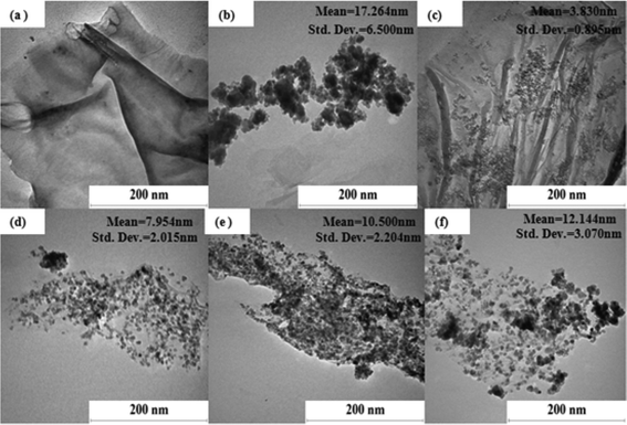 |
| | Fig. 1 TEM images of G1 (a), F20 (b), G1F2 (c), G1F5 (d), G1F10 (e) and G1F20 (f) before the photocatalytic process. | |
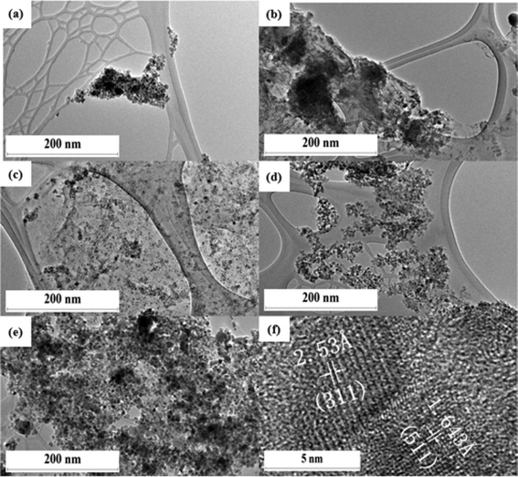 |
| | Fig. 2 HR-TEM images of F20 (a), G1F2 (b), G1F5 (c), G1F10 (d) and G1F20 Fe3O4/rGO (e) after 8 cycles of the photocatalytic process, and G1F20 (f) at a higher magnification. | |
3.2. XRD studies of Fe3O4/rGO nanocomposites
Fig. 3 portrays the representative XRD patterns of the G1, F20 and rGO/Fe3O4 nanocomposites, which coincide with the results from the HRTEM image (Fig. 2(f)), and confirm the formation of Fe3O4 crystallites in the nanocomposites. The XRD pattern of F20 (Fig. 3(e)) displays a series of diffraction peaks at 2θ = 30.2°, 35.6°, 43.3°, 53.7°, 57.3°, and 62.8°, corresponding to the reflections from the (220), (311), (400), (422), (511), and (440) crystal planes of the cubic spinel structure of magnetite Fe3O4. A sharp peak observed in G1 (Fig. 3(a)) at 2θ = 10.8° is assigned to the (001) reflection of GO, which indicates that the GO was incompletely reduced to rGO. For the sample rGO/Fe3O4 containing Fe2+ ions, this (001) plane was absent, which suggests that Fe2+ plays an important role as a reducing agent in the redox reaction of nanocomposite fabrication (Fig. 3(b)). For sample G1F2, this sharp XRD line was observed while the diffraction peaks for Fe3O4 were not detected, owing to the low amount of Fe2+ ions in the nanocomposite resulting from the partial reduction of GO. However, when increasing the content of Fe3O4, the five typical characteristic diffraction peaks of Fe3O4 and the disappearance of the graphitic peak were clearly observed for G1F5 and G1F10 (Fig. 3(c–d)). This can be ascribed to the formation of van der Waals and π–π stacking interactions between the rGO sheets being prevented by the Fe3O4 nanoparticles.21
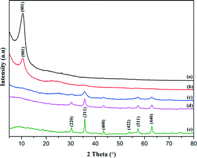 |
| | Fig. 3 XRD patterns of G1 (a), G1F2 (b), G1F5 (c), G1F10 (d), and (e) F20. | |
3.3. Raman spectral studies of Fe3O4/rGO nanocomposites
Raman spectroscopy is an excellent tool to investigate the ordered and disordered crystal structures of carbonaceous materials, viz. graphene, graphene oxide and reduced graphene oxide. Raman spectra of the GO, G1 and rGO/Fe3O4 photocatalyst materials were recorded, and are presented in Fig. 4. Fig. 4 (inset) shows the existence of a D band at around 1350 cm−1, which can be ascribed to the sp3 defects, while the G band at around 1580 cm−1 is related to the in-plane vibration of sp2 carbon atoms in a 2D hexagonal lattice of GO and rGO. The observed positions and intensities of the D and G bands highly influence the structural transformation in carbonaceous materials. The ID/IG ratio of the rGO/Fe3O4 nanocomposites (0.92–1.15) showed remarkable increases (Fig. 4(c–f)) over that of GO (0.91); this is due to the higher amount of Fe3O4 in the nanocomposite. The relatively high intensity of the D band when compared to the G band of rGO/Fe3O4 indicates the presence of localized sp3 defects within sp2 clusters during the functionalization process of the exfoliated GO.22,23 Additionally, the characteristic Raman peak around 670 cm−1 suggests the presence of magnetite (Fe3O4) (Fig. 4(c–g)). It is known from an earlier report that the observed broad peak at ~670 cm−1 is due to the presence of magnetite nanoparticles in the rGO/Fe3O4 nanocomposites.24
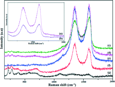 |
| | Fig. 4 Raman spectra for GO (a), G1 (b), G1F2 (c), G1F5 (d), G1F10 (e), G1F20 (f) and F20 (g). | |
3.4. Magnetic behaviour of Fe3O4/rGO nanocomposites
Studying the magnetic behaviour of the prepared magnetically separable rGO/Fe3O4 nanocomposites is essential. In this respect, VSM analysis was carried out at room temperature for both the bare Fe3O4 nanoparticles and the rGO/Fe3O4 nanocomposites, and the results are shown in Fig. 5. The bare Fe3O4 nanoparticles and the rGO/Fe3O4 nanocomposites showed typical S-like curve magnetization hysteresis loops with no coercivity, inferring that they exhibit super-paramagnetism, while their magnetization behaviours were removed in the absence of the applied magnetic field. The saturation magnetization (Ms) of the rGO/Fe3O4 nanocomposites increased from 1.63 emu g−1 to 30.30 emu g−1 with a increase in the content of Fe3O4 nanoparticles in the rGO sheets. The saturated magnetization value observed for the pristine Fe3O4 nanoparticles was 58.70 emu g−1, which was higher than that of the magnetic rGO/Fe3O4 nanocomposites. This can be attributed to the presence of graphene in the nanocomposites.25
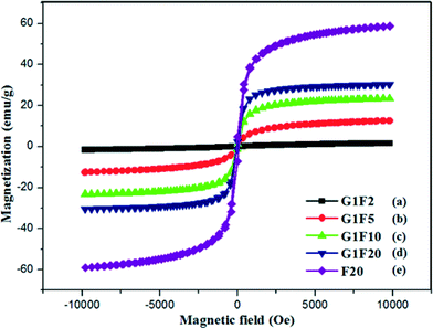 |
| | Fig. 5 VSM magnetization curves of G1F2 (a), G1F5 (b), G1F10 (c), G1F20 (d) and F20 (e). | |
3.5. Photoluminescence studies of rGO/Fe3O4 nanocomposites
Photoluminescence (PL) was used to study the electronic and optical properties of the nanocomposites, including the migration, transfer and recombination of electron–hole pair of the photoinduced semiconductor. Fig. 6 shows the room temperature PL spectra of rGO, the rGO/Fe3O4 nanocomposites and Fe3O4. It was observed from the PL spectra that the rGO and rGO/Fe3O4 nanocomposites exhibited lower PL intensities than that of the bare Fe3O4 nanoparticles. Fe3O4 is an indirect band gap semiconductor with a narrow optical gap value of 1.4 eV.26 This narrowness value arises from the d orbitals, suggesting that Fe3O4 exhibits a high electrical conductivity with an almost metallic nature at room temperature, but that the low charge carrier (electron and hole) mobility in Fe3O4 may lead to an increase in electron–hole recombination. Therefore, the higher PL intensity of the bare Fe3O4 is due to the recombination of excited electrons and holes, whereas the lower PL emission intensities of rGO and the Fe3O4/rGO nanocomposites are due to the lower charge recombination rates. This suggests that graphene has a tendency to greatly influence the PL intensities of rGO/Fe3O4 nanocomposites, owing to its 2D hexagonal π-conjugation structure and excellent electronic conductivity. The high charge mobility of graphene means that it acts as an electron acceptor for the photo-excited electrons from Fe3O4, leading to a low charge recombination rate.27–29 Among the prepared nanocomposites and rGO, G1F2 has the lowest PL intensity, which indicates that G1F2 efficiently suppresses electron–hole pair recombination and promotes charge separation; these are highly beneficial for photocatalytic applications. The synergistic effect30 between graphene and Fe3O4 nanoparticles in the G1F2 nanocomposite allows graphene to capture or trap the photo-induced electrons from the conduction band of the Fe3O4 through the extended π-conjugation carbon network, and consequently restrict the flash recombination of electron–hole pair. Therefore, G1F2 is expected to show higher photocatalytic activity when compared to the other nanocomposites.31 However, further increasing the Fe3O4 content in the rGO/Fe3O4 nanocomposite results in a higher PL intensity. The Fe3O4 nanoparticles possess large surface energies, and hence they tend to aggregate to minimize these surface energies. Thus, an excess amount of Fe3O4 nanoparticles in the rGO/Fe3O4 nanocomposite may lead to aggregation of the nanoparticles, resulting in larger particles.32 Consequently, increasing the amount of Fe3O4 nanoparticles in the rGO/Fe3O4 nanocomposite introduces new charge recombination centres for photoinduced charge separation, and as a consequence this decreases the photocatalytic efficiency.
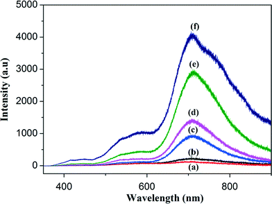 |
| | Fig. 6 Room temperature photoluminescence (PL) spectra of G1F2 (a), rGO (b), G1F5 (c), G1F10 (d), G1F20 (e) and F20 (f). | |
3.6. Photocatalytic activity of magnetically separable rGO/Fe3O4 nanocomposites for the degradation of methylene blue
The photocatalytic performances of the prepared photocatalytic materials viz. rGO, Fe3O4 and magnetically separable rGO/Fe3O4 nanocomposites were separately evaluated for the degradation of a model dye pollutant, methylene blue (MB) under natural sunlight irradiation for 5 h. The results of the photodegradation study are shown in Fig. 7(a). During the photocatalytic experiments, the bare Fe3O4 nanoparticles achieved only 57% photodegradation even after 5 h of sunlight irradiation (Fig. 7(a)). The poor photocatalytic performance of the bare Fe3O4 nanoparticles can be ascribed to the aggregation caused by the high surface area of Fe3O4 nanoparticles and the magnetic interactions between the particles, which lead to the formation of larger sized particles.33 Interestingly, a maximum photodegradation of MB was observed at 1 h light irradiation when a photocatalyst of Fe3O4 nanoparticles, incorporated into reduced graphene oxide sheets, was used. To optimize the Fe3O4 content for maximum photodegradation of MB dye, photocatalytic experiments were carried out with different compositions of rGO and Fe3O4. Among the photocatalysts, G1F2 exhibited excellent photocatalytic activity; almost 89% of the MB was decolourized after 30 min and 100% after 1 h light irradiation. GIF5, GIF10 and GIF 20 achieved 100% degradation of MB after 2 h of irradiation. Meanwhile, the bare Fe3O4 nanoparticle photocatalyst could achieve only 57% MB dye removal efficiency. The maximum photocatalytic activity exhibited by the rGO/Fe3O4 nanocomposite photocatalysts is due to the emergence of synergistic effects in the rGO/Fe3O4 during the photocatalytic reaction i.e. efficient photogenerated charge transfer from Fe3O4 to the graphene sheets, which facilitates increased electron–hole pair separation, and as a consequence a better photocatalytic performance is achieved.
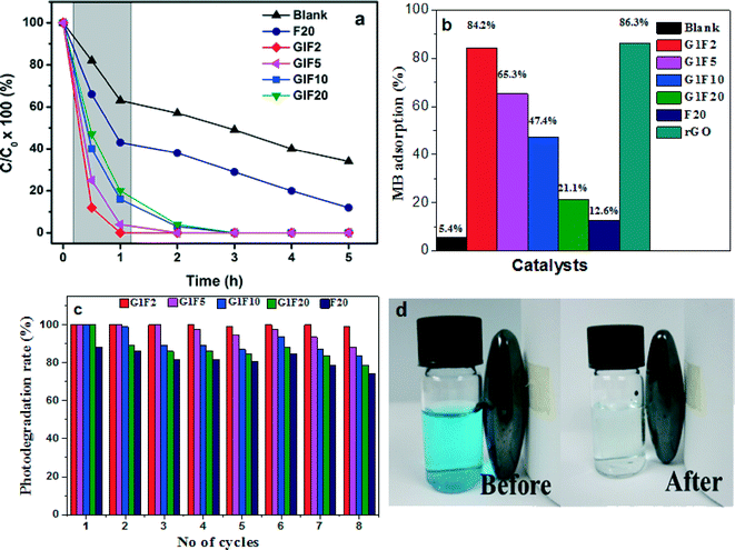 |
| | Fig. 7 Photocatalytic degradation of MB in the presence of different photocatalysts under sunlight irradiation (a). Adsorption of MB by different catalysts after 12 h stirring. (b). Photodegradation efficiency (%) of MB solution for 8 cycles in the presence of rGO/Fe3O4 nanocomposites and Fe3O4 (c). Photographic images of MB before and after degradation by rGO/Fe3O4 and recovery of the catalyst by applying an external magnet (d). | |
To further understand the enhanced photocatalytic performance of the rGO/Fe3O4 nanocomposites, the MB solution was continuously stirred with the photocatalysts overnight (12 h); the results are shown in Fig. 7(b). The rGO and GIF2 showed maximum adsorptions of ~86 and ~84%, respectively. Further increasing the Fe3O4 content in the nanocomposite led to a decrease in the adsorption of MB. The shadowed area in Fig. 7(a) follows a similar trend to the adsorption behaviour of the photocatalysts. The enhanced MB dye adsorptivity of the rGO/Fe3O4 photocatalysts is due to the large phenyl ring structure of the graphene34,35 in the nanocomposites. Moreover, graphene is a 2D crystalline structure and has a large surface area, superior electrical conductivity and unique transport properties, making it a great electron-transport material in the process of photocatalysis. When Fe3O4 nanoparticles are anchored on the surface of graphene sheets, the graphene provides more adsorption sites and photocatalytic reaction centres for the MB dye molecules through the π–π conjugation and electrostatic attraction between the MB dye and the aromatic region of the graphene sheets.36,37 These highly exposed surface active reaction sites are beneficial for promoting the generation of hydroxyl radicals for MB adsorption, by redox reactions within the active sites (Fe2+/Fe3+). Additionally, the strong Fe–O–C interactions of rGO/Fe3O4, between the delocalized unpaired π electrons from the π-conjugated carbon network on graphene's basal plane, facilities electron transfer between the rGO sheets and iron centres.38 Notably, the photocatalytic activity is highly dependent on the concentration of photogenerated charge carriers during the reaction.39 Therefore, the strong attachment of Fe3O4 on the electron carries of the rGO sheets gives rise to a enhanced migration of photoexcited electrons from the conduction band of Fe3O4 to the rGO sheets. The fast electron-transfer kinetics of rGO/Fe3O4 helps to improve the interfacial charge transfer process,40 leading to enhanced photocatalytic activity. On the other hand, the strong anisotropic dipolar interactions of Fe3O4 in aqueous phase41 are likely to diminish or restrict its catalytic activity, and thus the Fe3O4 nanoparticles are prone to aggregate into larger Fe3O4 particles (Fig. 1(b)), leading to decreased MB decolourization efficiency.
The sustainability of a photocatalyst is one of the most important requirements for successful practical applications. In this respect, the reusabilities of the rGO and rGO/Fe3O4 photocatalysts were investigated using the same photocatalyst for 8 sets of experiments, with fresh MB solution for each experiment, keeping all other experimental parameters constant. After each photodegradation experiment, the photocatalyst was removed from the photolysis cell using an external magnetic field and washed with high pure DI water, to remove the presence of any MB associated organic impurities. The magnetic separation technique represents an easy and convenient way to remove or recycle the photocatalyst. This can be achieved by placing a magnet close to the sample bottle, which causes the rGO/Fe3O4 photocatalyst to move towards the external magnetic field and be attracted to the side of the bottle, leaving behind a clear reaction solution (Fig. 7(d)). Therefore, the rGO/Fe3O4 can be easily reused and recycled after the photocatalytic process. The MB dye molecules could be effectively photodecomposed in each experimental cycle and no significant change in the photocatalytic activity of the G1F2 nanocomposite was observed during the repeated photocatalytic experimental cycles (Fig. 7(c)).
Among the different photocatalysts, the G1F2 nanocomposite exhibited the best stability during photocatalytic degradation of MB dye; hence it can be applied as a recyclable photocatalyst. The lower the content of Fe3O4 nanoparticles in the nanocomposites, the smaller the particle sizes are, with a high surface area and without heavy aggregation of Fe3O4 nanoparticles. Therefore they can offer excellent decolourization activity. Hence, G1F2 contains the lowest amount of Fe3O4 nanoparticles, and so has smaller particle sizes with high specific surface area, offering a number of active sites for the adsorption and subsequent desorption of MB molecules in the nanocomposite. This favours the facile transport of photoexcited electrons to reach the surface reaction sites more easily42 and thereby efficiently inhibits the recombination of photo-induced electron–hole pairs during the electron-transfer process. Thus, the higher photocatalytic activity and sustainability of this magnetically separable rGO/Fe3O4 nanocomposite is greatly beneficial for industrial waste water treatment processes.
The schematic representation of MB degradation in the presence of the magnetically separable rGO/Fe3O4 photocatalyst is shown in Fig. 8. Upon light irradiation, the Fe3O4 present on the rGO sheet surface undergoes charge separation that leads to promotion of valence band (VB) electrons into the conduction band (CB), leaving a hole in the VB (eqn (1)), whereas the MB molecules are excited to cationic MB radicals (MB*) (eqn (2)). These photogenerated electrons in the conduction band are instantaneously transferred to rGO sheets (eqn (3)), and are consequently captured by dissolved O2 to generate reactive oxidation species such as ˙OH and O2˙− (eqn (4)). On the other hand, the photoinduced holes are crucial for the oxidation process and adsorbents are effectively oxidized; usually the Fe3O4(h+) can react with adsorbed H2O/OH− to form strong hydroxyl radicals (˙OH) (eqn (5)). Finally, these ˙OH radicals oxidize the MB molecules adsorbed to CO2 and H2O (eqn (6))43via the π–π stacking/electrostatic interactions on the active sites of the rGO/Fe3O4 nanocomposites.
| | | Fe3O4 + hν → Fe3O4(e− + h+) | (1) |
| | | Fe3O4 + graphene → Fe3O4 + graphene(e−) | (3) |
| | | Graphene(e−) + O2 → graphene + O2˙ − | (4) |
| | | Fe3O4(h+) + OH− → Fe3O4 + ˙OH | (5) |
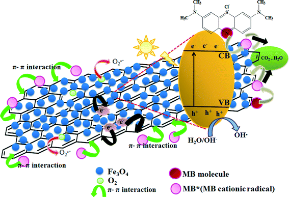 |
| | Fig. 8 Schematic representation of the photocatalytic degradation of MB in the rGO/Fe3O4 nanocomposites under natural sunlight irradiation. | |
4. Conclusion
We have reported the preparation of photocatalysts based on magnetically separable rGO/Fe3O4 nanocomposite materials, through a simple, eco-friendly and cost-effective approach at room temperature. The obtained nanocomposite materials were characterized by various suitable techniques such as HRTEM, XRD, and VSM analyses, Raman spectroscopy, PL and UV-vis spectrophotometry. The XRD pattern indicated the formation of Fe3O4–rGO nanocomposites and the HRTEM images showed that the Fe3O4 nanoparticles with an average size of 10 nm were incorporated into the rGO sheets. The super-paramagnetic properties of the rGO/Fe3O4 nanocomposite materials were revealed through VSM analysis. This super-paramagnetic behaviour of the rGO/Fe3O4 nanocomposites is highly advantageous when designing a solid-solution system for photocatalytic applications, as it facilitates the simple physical separation of the catalyst from the solution, in contrast to the other colloidal photocatalyst systems. The rGO/Fe3O4 exhibited excellent adsorption behaviour and enhanced photocatalytic performances towards the degradation of methylene blue (MB) dye compared to other samples such as rGO and pristine Fe3O4 nanoparticles. This enhanced photocatalytic activity could be attributed to the emergence of synergistic effects between the rGO and Fe3O4 and also to the reduced charge recombination. The rGO/Fe3O4 possessed good sustainability even after eight cycles of MB photodegradation, and moreover the morphology of the photocatalyst was unaffected. These features of magnetically separable rGO/Fe3O4 make it a promising and recyclable photocatalyst for many environmental remediation applications.
Conflict of interests
The authors declares that there is no conflict of interests regarding the publication of this research article.
Acknowledgements
This work was financially supported by the Exploratory Research Grant Scheme (ER016-2011A), the Fundamental Research Grant Scheme (UKM-FST-07-FRGS0233-2010), and a High Impact Research Grant from the Ministry of Higher Education of Malaysia (UM.C/625/1/HIR/MOHE/05).
References
- G. Williams, B. Seger and P. V. Kamat, J. Am. Chem. Soc., 2008, 2, 1487–1491 CAS.
- X. M. Chen, G. H. Wu, Y. Q. Jiang, Y. R. Wang and X. Chen, Analyst, 2011, 136, 4631–4640 RSC.
- H. T. Hu, X. B. Wang, F. M. Liu, J. C. Wang and C. H. Xu, Synth. Met., 2011, 161, 404–410 CrossRef CAS PubMed.
- J. F. Shen, B. Yan, M. Shi, H. W. Ma, N. Li and M. X. Ye, J. Mater. Chem., 2011, 21, 3415–3421 RSC.
- G. Z. Liao, S. Chen, X. Quan, H. T. Yu and H. M. Zhao, J. Mater. Chem., 2012, 22, 2721–2726 RSC.
- M. S. A. Sher Shah, A. R. Park, K. Zhang, J. H. Park and P. J. Yoo, ACS Appl. Mater. Interfaces, 2012, 4, 3893–3901 CAS.
- J. Zhang, Z. Xiong and X. Zhao, J. Mater. Chem., 2011, 21, 3634–3640 RSC.
- X. Y. Li, X. Wang, S. Y. Song, D. P. Liu and H. J. Zhang, Chem. – Eur. J., 2012, 18, 7601–7607 CrossRef CAS PubMed.
- Z. J. Luo, H. J. Tang, L. L. Qu, T. T. Han and X. Y. Wu, CrystEngComm, 2012, 14, 5710–5713 RSC.
- H. X. Wu, G. Gao, X. J. Zhou, Y. Zhang and S. W. Guo, CrystEngComm, 2012, 14, 499–504 RSC.
- D. M. Fouad and M. B. Mohamed, J. Nanotechnol., 2011, 1–7, DOI:10.1155/2011/416060.
- C. M. Yu, L. L. Gou, X. H. Zhou, N. Bao and H. Y. Gu, Electrochim. Acta, 2011, 56, 9056–9063 CrossRef CAS PubMed.
- E. M. Rodríguez, G. Fernández, P. M. Álvarez, R. Hernández and F. J. Beltrán, Appl. Catal., B, 2011, 102, 572–583 CrossRef PubMed.
- K. Wang, L. X. Yu, S. Yin, H. N. Li and H. M. Li, Pure Appl. Chem., 2009, 81, 2327–2335 CAS.
- W. H. Shi, J. X. Zhu, D. H. Sim, Y. Y. Tay, Z. Y. Lu, X. J. Zhang, Y. Sharma, M. Srinivasan, H. Zhang, H. H. Hng and Q. Y. Yan, J. Mater. Chem., 2011, 21, 3422–3427 RSC.
- Y. Fu and X. Wang, Ind. Eng. Chem. Res., 2011, 50, 7210–7218 CrossRef CAS.
- H. K. He and C. Gao, ACS Appl. Mater. Interfaces, 2011, 2, 3201–3210 Search PubMed.
- J. J. Liang, Y. F. Xu, D. Sui, L. Zhang, Y. Huang, Y. F. Ma, F. F. Li and Y. S. Chen, J. Phys. Chem. C, 2010, 114, 17465–17471 CAS.
- Y. S. Fu, H. Q. Chen, X. Q. Sun and X. Wang, Appl. Catal., B, 2012, 111–112, 280–287 CrossRef CAS PubMed.
- H. N. Lim, N. M. Huang, S. S. Lim, I. Harrison and C. H. Chia, Int. J. Nanomed., 2011, 6, 1817–1823 CrossRef CAS PubMed.
- X. W. Wang, H. W. Tan, Y. Yang, H. Wang, S. M. Wang, W. T. Zheng and Y. C. Liu, J. Alloys Compd., 2012, 524, 5–12 CrossRef CAS PubMed.
- M. Sathish, T. Tomai and I. Honma, J. Power Sources, 2012, 217, 85–91 CrossRef CAS PubMed.
- V. Chandra, J. S. Park, Y. Chun, J. W. Lee, I. C. Hwang and K. S. Kim, ACS Nano, 2010, 4, 3979–3986 CrossRef CAS PubMed.
- K. Ritter, M. S. Odziemkowski and R. W. Gillham, J. Contam. Hydrol., 2002, 55, 87–111 CrossRef CAS.
- L. L. Ren, S. Huang, W. Fan and T. X. Liu, Appl. Surf. Sci., 2011, 258, 1132–1138 CrossRef CAS PubMed.
- D. Beydoun, R. Amal, G. K.-C. Low and S. McEvoy, J. Phys. Chem. B, 2000, 104, 4387–4396 CrossRef CAS.
- X. J. Liu, L. K. Pan, T. Lv, G. Zhu, T. Lu, Z. Sun and C. Q. Sun, RSC Adv., 2011, 1, 1245–1249 RSC.
- Y. Zhang, G. Li, H. Lu, Q. Lv and Z. Sun, RSC Adv., 2014, 4, 7594–7600 RSC.
- D. K. Padhi and K. Parida, J. Mater. Chem. A, 2014, 2, 10300–10312 CAS.
- L. Zhou, Y. Shao, J. Liu, Z. Ye, H. Zhang, J. Ma, Y. Jia, W. Gao and Y. Li, ACS Appl. Mater. Interfaces, 2014, 6, 7275–7285 CAS.
- Y. Fu and X. Wang, Ind. Eng. Chem. Res., 2011, 50, 7210–7218 CrossRef CAS.
- M. Gao, W. Li, J. Dong, Z. Zhang and B. Yang, World J. Condens. Matter Phys., 2011, 1, 49 CAS.
- W. Wu, Q. G. He and C. Z. Jiang, Nanoscale Res. Lett., 2008, 3, 397–415 CrossRef CAS PubMed.
- Y. Matsumoto, M. Koinuma, S. Ida, S. Hayami, T. Taniguchi, K. Hatakeyama, H. Tateishi, Y. Watanabe and S. Amano, J. Phys. Chem. C, 2011, 115, 19280–19286 CAS.
- J. C. Qu, C. L. Ren, Y. L. Dong, Y. P. Chang, M. Zhou and X. G. Chen, Chem. Eng. J., 2012, 211–212, 412–420 CrossRef CAS PubMed.
- T. G. Xu, L. W. Zhang, H. Y. Cheng and Y. F. Zhu, Appl. Catal., B, 2011, 101, 382–387 CrossRef CAS PubMed.
- Y. S. Fu, P. Xiong, H. Q. Chen, X. Q. Sun and X. Wang, Ind. Eng. Chem. Res., 2012, 51, 725–731 CrossRef.
- K. Jasuja, J. Linn, S. Melton and V. Berry, J. Phys. Chem. Lett., 2010, 1, 1853–1860 CAS.
- A. Mukherji, B. Seger, G. Q. Lu and L. Wang, ACS Nano, 2011, 5, 3483–3492 CrossRef CAS PubMed.
- S. Saha, J. Wang and A. Pal, Sep. Purif. Technol., 2012, 89, 147–159 CrossRef CAS PubMed.
- J. Deng, X. Wen and Q. Wang, Mater. Res. Bull., 2012, 47, 3369–3376 CrossRef CAS PubMed.
- K. Parida, K. Reddy, S. Martha, D. Das and N. Biswal, Int. J. Hydrogen Energy, 2010, 35, 12161–12168 CrossRef CAS PubMed.
- T. Harifi and M. Montazer, Appl. Catal., A, 2014, 473, 104–115 CrossRef CAS PubMed.
|
| This journal is © The Royal Society of Chemistry 2014 |
Click here to see how this site uses Cookies. View our privacy policy here.  Open Access Article
 *a and
Chia Chin
Hua
d
![[thin space (1/6-em)]](https://www.rsc.org/images/entities/char_2009.gif) :
:![[thin space (1/6-em)]](https://www.rsc.org/images/entities/char_2009.gif) FeSO4)
FeSO4)![[thin space (1/6-em)]](https://www.rsc.org/images/entities/char_2009.gif) :
:![[thin space (1/6-em)]](https://www.rsc.org/images/entities/char_2009.gif) 2
2![[thin space (1/6-em)]](https://www.rsc.org/images/entities/char_2009.gif) :
:![[thin space (1/6-em)]](https://www.rsc.org/images/entities/char_2009.gif) 5
5![[thin space (1/6-em)]](https://www.rsc.org/images/entities/char_2009.gif) :
:![[thin space (1/6-em)]](https://www.rsc.org/images/entities/char_2009.gif) 10
10![[thin space (1/6-em)]](https://www.rsc.org/images/entities/char_2009.gif) :
:![[thin space (1/6-em)]](https://www.rsc.org/images/entities/char_2009.gif) 20
20


