Gas-core triple emulsions for ultrasound triggered release†
Haosheng
Chen
ab,
Jiang
Li
*cd,
Jiandi
Wan
de,
David A.
Weitz
b and
Howard A.
Stone
*d
aState Key Laboratory of Tribology, Tsinghua University, Beijing 100084, China
bSchool of Engineering and Applied Sciences, Department of Physics, Harvard University, Cambridge, MA 02138, USA
cSchool of Mechanical Engineering, University of Science and Technology Beijing, Beijing 100083, China. E-mail: lijiang@ustb.edu.cn
dDepartment of Mechanical and Aerospace Engineering, Princeton University, Princeton, NJ 08544, USA. E-mail: hastone@princeton.edu
eMicrosystems Engineering, Rochester Institute of Technology, Rochester, NY 14623, USA
First published on 22nd October 2012
Abstract
Gas-in-oil-in-water-in-oil triple emulsions are fabricated with a microfluidic method. The encapsulating layers can be triggered for release by ultrasound, owing to the gas core. Due to the stability in the atmosphere, the emulsions are polymerized by using UV light outside the device to fabricate compound particles with a gas-in-liquid-in-solid structure.
Suspensions, emulsions and foams are common multiphase materials that are used in many forms of processing, including coating, food products, and formulations of therapeutic drug delivery systems. In most applications, the size distribution, stability, and structure of the particulate phase play important roles. As but one example among many, microbubbles encapsulated by lipids or thin shells of polymers are used as ultrasound contrast imaging agents and drug delivery vehicles.1–7 The complex hierarchical structures required for many of these applications can be formed using monodisperse emulsion templates, which can be produced using microfluidic technologies.8 For example, highly controlled oil-in-water-in-oil-in-water triple emulsions have been created by using microcapillary devices.9,10 Similar double emulsions, in the form of micrometer-dimension gas bubbles encapsulated in drops, have been made with microfluidic methods and have been shown to form closed-shell foams and porous particles.11,12 In the pharmaceutical area, multiple emulsions offer the possibility of encapsulating, respectively, hydrophobic and hydrophilic drugs in the oil and aqueous phases. Similarly, microbubbles encapsulated in thin shells can act as reactive cores or “triggers” that respond to external ultrasound and can be used in drug delivery applications.13–16
The combination of multiple emulsions with microbubbles to form ultrasound-responsive emulsions would offer even greater benefits. For example, more complex structures with gas cores surrounded by multiple shells of different liquids or elastic materials offer the possibility of simultaneously encapsulating different materials while still being responsive to ultrasound. For example, either hydrophobic or hydrophilic drugs can be loaded, respectively, in the oil phase and the aqueous phase of the gas-core triple emulsions; the drugs or active materials that are loaded in the encapsulating layers can be protected from contamination by the environment and so retain their activity before being released.17–19 Controlled production of such hierarchical structures has, however, never been reported, and we provide an experimental demonstration of one approach to this idea.
We present here a microfluidic method to fabricate monodisperse gas-core triple emulsions, which have the structure of gas-in-oil-in-water-in-oil (G/O1/W/O2). The gas-core triple emulsions are stable in the atmosphere, which enables the drops to be polymerized with UV light outside of the device to form more stable compound particles with a gas core. We show that the gas core responds to ultrasound, making it possible to break the emulsions and the particles and release the encapsulated content, which is here a dye that could just as well be a drug.
We make use of a microfluidic glass capillary device, as shown in Fig. 1(a) and (b), to generate the gas-core triple emulsions, where a drop containing a single gas bubble is encapsulated inside a large drop (Fig. 1(c)). The injection tube for the oil phase is a cylindrical glass capillary with an outer diameter of 1.0 mm. After being tapered using a pipette puller, the resultant capillary has an inner diameter of 120 μm. The collection tube is tapered to have an inner diameter of 200 μm, and then treated with octadecyltrichlorosilane at the tip to make it hydrophobic. Both the tapered injection tube and the collection tube are fitted into either end of a square capillary with an inner dimension of 1.05 mm. Finally, the injection tube for the gas phase, with an outer diameter of 80 μm, is fitted into the injection tube for the oil phase from the untapered end.
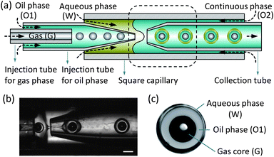 | ||
| Fig. 1 Experimental apparatus. (a) Schematics of the devices for fabricating the gas-core triple emulsions. (b) Formation of gas-core triple emulsions in the microcapillary device as indicated by the dashed line in (a), and a video is available in the ESI.† (c) An image of a triple emulsion drop, where the white spot in the middle of the black gas core is a reflection of the illumination. The scale bar is 200 μm. | ||
To form the gas-core triple emulsion, we use one gas phase and two immiscible liquid phases. The innermost gas phase (G) flows through its injection tube at a pressure of pG = 5 psi. The oil phase (O1) flows through its injection tube at a flow rate QO1. The aqueous phase (W) flows through the interstices between the square capillary and the injection tube for the oil phase at a flow rate QW. The continuous phase (O2) enters the device through the interstices on the other end of the square capillary at a flow rate QO2 (Fig. 1(a)). When the phases meet at the junction, a G/O1/W/O2 triple emulsion is generated, as shown by the experimental images in Fig. 1(b). The liquid flow rates are controlled by syringe pumps (Harvard Apparatus Co.), and the size of the gas core and the drop is controlled by adjusting the flow rate ratios of the different phases. A high-speed camera (Phantom V9.0) attached to a microscope is used to image the formation of the triple emulsion droplets.
Using the microfluidic device, the gas-core triple emulsions (G/O1/W/O2) are produced with controlled sizes of both the gas cores and the shells. Here, the innermost phase (G) is air; both the oil phase (O1) and the continuous phase (O2) are polydimethylsiloxane (PDMS) oil containing 2 wt% surfactant of Dow Corning 749, which is a blend of 50 vol% high molecular weight resin and 50 vol% volatile, low viscosity cyclopenta siloxane; and the aqueous phase (W) is water with 10 wt% polyvinyl alcohol (PVA). The size of the gas core (G) is controlled by adjusting the flow rate of the oil phase (O1). For example, when the flow rate QO1 is increased from 500 to 1500 μl h−1, while maintaining the flow rates of all other phases constant, the diameter of the gas core decreases from 105 ± 0.5 to 78 ± 0.5 μm, while the encapsulating droplet has only a small variation in diameter from 169 ± 1.8 to 173 ± 2.6 μm (Fig. 2(a)). The size of the encapsulating droplet is adjusted by controlling the flow rate of the continuous phase (O2). When the flow rate QO2 is increased from 6000 to 12![[thin space (1/6-em)]](https://www.rsc.org/images/entities/char_2009.gif) 000 μl h−1, while maintaining the flow rates of the other phases constant, the diameter of the entire drop decreases about a factor of two from 169 ± 1.8 to 82 ± 2.2 μm and the diameter of the gas core also decreases by about a factor of two from 105 ± 0.5 to 53 ± 1.4 μm (Fig. 2(b)). Thus, the thickness of both the encapsulating layers and the gas core of the emulsions can be controlled. For each flow-rate ratio, the triple emulsions are monodisperse, as shown by the error bars of the drop diameter in Fig. 2.
000 μl h−1, while maintaining the flow rates of the other phases constant, the diameter of the entire drop decreases about a factor of two from 169 ± 1.8 to 82 ± 2.2 μm and the diameter of the gas core also decreases by about a factor of two from 105 ± 0.5 to 53 ± 1.4 μm (Fig. 2(b)). Thus, the thickness of both the encapsulating layers and the gas core of the emulsions can be controlled. For each flow-rate ratio, the triple emulsions are monodisperse, as shown by the error bars of the drop diameter in Fig. 2.
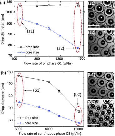 | ||
| Fig. 2 Controlled size of the gas-core triple emulsion drops. (a) The diameter of the gas core decreases with QO1 changing from 500 to 1500 μl h−1, with the flow rates QW:QO2 = 1000:6000 μl h−1 and the gas pressure 5 psi; (a1) and (a2) are the images of the fabricated triple emulsion droplets at QO1 = 500 and 1500 μl h−1, respectively. (b) The drop diameter decreases with QO2 changing from 6000 to 12000 μl hr−1, with the flow rates QO1:QW = 1000:1000 μl h−1 and the gas pressure 5 psi; (b1) and (b2) are the images of the fabricated triple emulsion droplets at QO2 = 6000 and 12000 μl h−1, respectively. The scale bar in each image is 200 μm. | ||
This kind of gas-core triple emulsion (G/O1/W/O2) is much more stable than gas-core double emulsions (G/O1/W) with a similar structure. Our studies demonstrating the enhanced stability of the gas-core emulsions are reported in Fig. 3. The gas-core double emulsions (G/O1/W) are made without flowing the continuous phase O2 using the same microfluidic device, where QO1:QW = 1000:8000 μl h−1 and pG = 5 psi. The G/O1/W emulsions break up after flowing out of the collection tube, and usually survive only a few minutes, as illustrated in Fig. 3(a). However, the triple emulsions (Fig. 3(b)) can last for more than two days with no apparent change in their shapes and structures except for a small expansion of the gas cores. During this time, the aqueous layer becomes thinner, and the diameter of the entire droplet decreases, whereas the diameter of the gas core increases. After a week, the aqueous layers become much thinner and some of the emulsion drops rupture. We attribute the enhanced stability of the triple emulsions to the double encapsulating layers that provide an extra layer for protection and also serve as a diffusion barrier, which minimizes dissolution of the gas and organic phases.
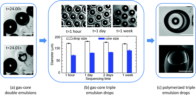 | ||
| Fig. 3 Stability of the gas-core triple emulsions (G/O1/W/O2) compared to gas-core double emulsions (G/O1/W). (a) After flowing outside the device, the G/O1/W double emulsion droplet breaks up in tens of seconds as imaged by a fast camera. (b) The morphologies of the stable G/O1/W/O2 triple emulsion droplets after being collected outside of the device for 1 hour, 1 day and 1 week; statistical distributions of the drop and gas core diameters are shown. (c) Optical (top) and SEM (bottom) images of a compound particle obtained by polymerization of the gas-core triple emulsion outside of the device. The compound particle has a unique structure containing the three phases of solid, liquid and gas. The scale bars are 200 μm. | ||
The stability of the triple emulsions is further enhanced upon polymerization of the shell. For the gas-core double emulsions, polymerization using in situ UV irradiation is required because the gas cores are not stable outside the device due to the pressure difference between the gas core and the atmosphere. Thus, the emulsions must be exposed to UV radiation while they are fabricated to induce polymerization of the emulsions; however, we have found that this step sometimes causes clogging of the microfluidic devices. In contrast, because they remain stable in the atmosphere, the gas-core triple emulsions can be polymerized after being removed from the microfluidic device and collected. Therefore, the fabrication of the emulsion and its polymerization can be separated into two distinct processes, and exposure to UV light can be restricted to the polymerization process. Thus, this approach reduces the exposure time of UV light, which makes polymerization safer and more efficient; moreover, it also avoids the possibility of clogging the device.
To demonstrate the long-term stability of the triple emulsions imparted by the polymerization step, we use an aqueous solution of a UV sensitive polymer as the aqueous phase (W), which is made of 70 vol% polyethylene glycol diacrylate, 5 vol% 2-hydroxy-2-methylpropiophenone, 1 vol% triton x-100, 0.5 wt% sodium dodecyl sulfate and 23.5 vol% pure water. As an example, we give results for a gas-core triple emulsion made using a flow rate ratio of QO1:QW:QO2 = 2000:4000:12000 μl h−1 and a gas pressure of 5 psi. The triple emulsion droplets are collected outside of the device where they are exposed to UV light for about 10 seconds to polymerize the aqueous phase. The final particles are gas-in-liquid-in-solid (G/L/S) compound particles, as shown by the optical and SEM images in Fig. 3(c).
A major advantage of these hierarchical structures is that the gas core makes them responsive to ultrasound, which we next demonstrate. In particular, ultrasound can be used to trigger the release of the gas core, breaking the emulsion structure. To illustrate this idea, a G/O1/W/O2 triple emulsion and an O1/W/O2 double emulsion are produced in a microfluidic device, where the O1/W/O2 double emulsion is made with QO1:QW:QO2 = 500:1000:6000 μl h−1 and without flowing the gas phase G (a video is available in the ESI†). Both the G/O1/W/O2 triple emulsion and the O1/W/O2 double emulsion are injected into a polyethylene tube with an inner diameter of 860 μm. Part of the tube is fixed horizontally on the bottom of a Petri dish and immersed in pure water. The tip of an Ultrasonic Dismembrator (model 150E, Fisher Scientific Inc.), with a diameter of 3 mm, is immersed in the water and mounted above the tube at a distance of 2.5 mm. It is operated at a frequency of 40 kHz, and the peak displacement of the tip is 15 μm.
We observe that the ultrasound triggers breakup of the gas-core triple emulsion, as shown by the experimental sequence of images in Fig. 4(a1)–(a3). In the experiment shown, five G/O1/W/O2 emulsion droplets and one O1/W/O2 emulsion droplet are injected to the position under the ultrasonic tip. As shown in Fig. 4(a1) and (a2), respectively, the triple emulsion droplets float near the top while the double emulsion droplet sinks to the bottom because the density of the gas-core triple emulsion drops is lower than that of the double emulsion drops. Prior to turning on the ultrasound, all the droplets maintain their structures. But when the ultrasonic tip starts to vibrate, the double emulsion droplet without a gas core maintains its structure and even stays at its original position, while the gas-core triple emulsion droplets break up and the contents are released. This release of the triple emulsions happens within 30 ms, and the ultrasound pushes the remaining parts of the droplets forward by a few hundred microns (Fig. 4(a3)).
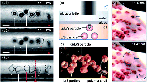 | ||
| Fig. 4 Ultrasound-triggered release of gas-core drop and gas-core particle. (a1)–(a3) The triggered release of the gas-core triple emulsion (G/O1/W/O2) drops in polyethylene tubing. (a1) and (a2) show the same drops from different focusing distances before the ultrasound is applied. (a3) The gas-core triple emulsion drops, indicated by the arrows, break up upon the ultrasound trigger, while the double emulsion (O1/W/O2) drop, indicated by the dashed arrow, does not rupture. The dashed line with a triangle shows the position of the right edge of the ultrasonic tip. (b) The schematic side view of the triggered release of the gas-core particle. The hollow arrow indicates the position of the camera for (d1) and (d2). (c) The dry G/L/S and L/S compound particles in air, where the light areas in the center of the G/L/S particles are gas bubbles. The polymer shell of a broken particle is shown for comparison. A corresponding image of the compound particles taken under an optical transmission microscope and an SEM image of the polymer shell of a released particle are available in the ESI.† (d1) and (d2) show the triggered release of the G/L/S particle. The GLS particle, indicated by an arrow, breaks into two parts, indicated by the two dashed circles, upon the ultrasound trigger. Circle i indicates the released oil phase, while circle ii indicates the polymer shell. All the scale bars are 200 μm. | ||
The second example we describe is the ultrasound-triggered release of a gas-core compound particle. We accomplish this by tracking particles, which have been dyed, as shown in the schematic in Fig. 4(b). Both gas-in-liquid-in-solid (G/L/S) particles and liquid-in-solid (L/S) particles are made (Fig. 4(c)). G/O1/W/O2 and O1/W/O2 emulsions are generated first, with the same methods as above, to fabricate G/L/S and L/S compound particles, respectively, while 0.1 wt % Sudan III is added to the O1 phase as a dye. The generated emulsions are collected in a Petri dish with a cross-linked PDMS (Sylgard 184 Silicone Elastomer Kit) sheet on the bottom. The emulsion is left in air for 12 hours, so that the O2 phase is absorbed by the PDMS sheet while the aqueous phase evaporates. Consequently, dry compound particles, with a thin layer of transparent PVA polymer shell encapsulating the inner phase(s), are obtained. Before the ultrasonic experiment, the G/L/S particle is suspended in the oil with several L/S particles; the suspension is sealed by a glass slide at a distance of 1 mm from the bottom, and immersed in water with the ultrasonic tip mounted 2.5 mm away. A digital camera (Nikon D90) with a bellow (Nikon PB-5) and a macro lens (SIGMA F2.8 EX DG) is used to take images at an angle of 45°. The G/L/S particle, which is indicated by an arrow in Fig. 4(d1) and (d2), breaks into two parts upon the ultrasound trigger (Fig. 4(d2)): the dyed oil phase diffuses away (circle i) and separates from the polymer shell (circle ii). No changes are observed in the L/S particles. Hence, again the hierarchical gas-core droplets allow triggered release. The two examples illustrate that the controlled release near a target site is possible for both the gas-core compound droplets and the gas-core compound particles under an external ultrasound trigger, while compound droplets and particles without a gas core are not sensitive to the trigger.
In summary, the gas-in-oil-in-water-in-oil structure of gas-core triple emulsions makes them a potential multi-functional particle for drug delivery or other applications of controlled release. The double encapsulating layers stabilize the emulsion and reduce the exposure time of UV light during the polymerization. This approach generates gas-in-liquid-in-solid compound particles. The gas core encapsulated inside can both act as a contrast agent and induce controlled release upon application of ultrasound. Therefore, the gas-core triple emulsions are a promising platform for further study and potential applications.
This research is supported by NSFC Project (50975158 and 50805008). The work at Harvard University was supported by the NSF (DMR-10006546) and the Harvard MRSEC (DMR-0820484).
Notes and references
- S. Qin, C. F. Caskey and K. W. Ferrara, Phys. Med. Biol., 2009, 54, R27 CrossRef.
- E. Stride and M. Edirisinghe, Soft Matter, 2008, 4, 2350 RSC.
- V. Frenkel, Adv. Drug Delivery Rev., 2008, 60, 1193 CrossRef CAS.
- M. Kinoshita, N. McDannold, F. A. Jolesz and K. Hynynen, Proc. Natl. Acad. Sci. U. S. A., 2006, 103, 11719 Search PubMed.
- J. I. Park, D. Jagadeesan, R. Williams, W. Oakden, S. Chung, G. J. Stanisz and E. Kumacheva, ACS Nano, 2010, 4, 6579 CrossRef CAS.
- B. E. O'Neill and K. C. Li, Int. J. Hyperthermia, 2008, 24, 506 Search PubMed.
- Y. Steinberg, A. Schroeder, Y. Talmon, J. Schmidt, R. L. Khalfin, Y. Cohen, J. M. Devoisselle, S. Begu and D. Avnir, Langmuir, 2007, 23, 12024 CrossRef CAS.
- R. K. Shah, H. C. Shum, A. C. Rowat, D. Lee, J. J. Agresti, A. S. Utada, L. Y. Chu, J. W. Kim, A. Fernandez-Nieves, C. J. Martinez and D. A. Weitz, Mater. Today, 2008, 11, 18 CrossRef CAS.
- L. Y. Chu, A. S. Utada, R. K. Shah, J. W. Kim and D. A. Weitz, Angew. Chem., Int. Ed., 2007, 46, 8970 CrossRef CAS.
- A. R. Abate and D. A. Weitz, Small, 2009, 5, 2030 CrossRef CAS.
- E. Talu, M. M. Lozano, R. L. Powell, P. A. Dayton and M. L. Longo, Langmuir, 2006, 22, 9487 CrossRef CAS.
- J. Wan, A. Bick, M. Sullivan and H. A. Stone, Adv. Mater., 2008, 20, 3314 CrossRef CAS.
- J. E. Chomas, P. Dayton, D. May and K. Ferrara, J. Biomed. Opt., 2001, 6, 141 Search PubMed.
- V. Sboros, C. M. Moran, S. D. Pye and W. N. McDicken, Ultrasound Med. Biol., 2001, 27, 1367 Search PubMed.
- K. Tiemann, C. Veltmann, A. Ghanem, S. Lohmaier and M. Bruce, Ultrasound Med. Biol., 2001, 27, 1525 Search PubMed.
- K. Ferrara, R. Pollard and M. Borden, Annu. Rev. Biomed. Eng., 2007, 9, 415 CrossRef CAS.
- S. L. Huang and R. C. MacDonald, Biochim. Biophys. Acta, Biomembr., 2004, 1665, 134 CrossRef CAS.
- N. Rapoport, W. G. Pitt, H. Sun and J. L. Nelson, J. Controlled Release, 2003, 91, 85 CrossRef CAS.
- E. C. Unger, T. P. McCreery, R. H. Sweitzer, V. E. Caldwell and Y. Wu, Invest. Radiol., 1998, 33, 886 CrossRef CAS.
Footnote |
| † Electronic Supplementary Information (ESI) available: Video for Fig. 1(b) is shown in G_O1_W_O2_triple-Fig1b.avi; video for the fabrication of the O1/W/O2 double emulsion used in Fig. 4(a) is shown in O1_W_O2_double-Fig4a.avi; a microscope image for comparison with Fig. 4(c) is shown in compound_particles-Fig4c.tif with a scale bar of 200 μm; an SEM image of a released shell of the G/L/S particles in Fig. 4(c) is shown in SEM_shell-Fig4c.tif. See DOI: 10.1039/c2sm26992a |
| This journal is © The Royal Society of Chemistry 2013 |