Advances in anti-scale magnetic water treatment
Adetunji
Alabi
a,
Matteo
Chiesa
b,
Corrado
Garlisi
a and
Giovanni
Palmisano
*a
aDepartment of Chemical and Environmental Engineering, Institute Center for Water and Environment (iWater), Masdar Institute of Science and Technology, PO BOX 54224, Abu Dhabi, UAE. E-mail: gpalmisano@masdar.ac.ae
bDepartment of Mechanical and Materials Engineering, Institute Center for Energy (iEnergy), Masdar Institute of Science and Technology, PO BOX 54224, Abu Dhabi, UAE
First published on 12th May 2015
Abstract
Scaling is the bane of households and industries that make use of water frequently. The consequences are so egregious that harmful chemicals have been sought after to remedy the situation. These chemicals, though efficacious, do more harm than good because they render water unsuitable for human consumption and cause ecological imbalance. Anti-scale magnetic water devices offer a cleaner solution to handling the scaling dilemma. This method of water treatment has been in existence for more than a century and is still the subject of much debate today, with the method being viewed with much skepticism, although evidence of its efficacy has been provided on countless occasions. Reports are given on several effects associated with magnetic water treatment, as well as proposed mechanisms. Yet no general consensus has been reached regarding the treatment method's mode of operation, which could explain the cynical reception magnetic water devices often receive. Insights into the enigmatic technique of magnetic water treatment attempt to explain magnetic effects on water and its constituents, citing explanations, which are unrelated to the current principles of magnetism. Several reports and accounts that involve the use and application of anti-scale magnetic water treatment are elucidated with special focus on calcium carbonate scale and its transformation.
Water impactScaling produces devastating effects on both households and industries. It causes pipe blockages, damage to desalination membranes, and reduction in efficiency of heat exchangers and boilers. Chemical treatment of scale is effective but renders water unfit for human use and potentially alters the ecological balance with release of substances capable of promoting eutrophication and algal blooms. A ‘greener’ means of addressing this issue must be brought forward. Anti-scaling magnetic units could be a potent alternative, because they cost less and are easy to install. The benefits are both economic and ecological – reduced expenditure on scale remediation, improved water conditions for human use and reduced release of harmful substances to the environment. |
1. Introduction
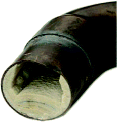
Scaling is the deposition of inverse solubility salts which have recrystallized from solution which form an encrustation on the surfaces they come in contact with (Fig. 1). It is also referred to as inorganic fouling or crystallization fouling. This frequently occurs as a result of changes in pH, temperature change, outgassing or pressure change affecting the solubility of the salts.1,2 Calcium carbonate is the most common constituent of scale.3,4 Other scale forming salts include magnesium carbonate, calcium sulphate, barium sulphate, strontium sulphate, iron carbonate, iron sulphide, and iron oxides. Also inclusive are the silicates and phosphates and oxides, or any of a variety of compounds with slight solubility in water. These scale forming salts are taken up when water comes into contact with rocks and sediments in the environment, producing water hardness.2. Significance of scaling
Scale build-up is a problem faced by countless industries such as wastewater treatment, desalination, oil and gas, petrochemicals, etc. The formation of scale is of economic importance to industries and households. For instance, it causes blockages in pipes and impedes fluid flow. Scale build-up also reduces the efficiency in heat exchangers and boilers by thermally insulating the heat exchange surface areas. This unwanted insulation can also lead to equipment failure in pressurized systems due to overheating of the metal surfaces. Furthermore, it results in degradation of equipment, increased downtime, and increased cost of maintenance and energy generation. In reverse osmosis systems, it contributes to flux decline and membrane degradation.5The impact of scaling can be so devastating that it was described as “one of the most serious evils with which engineers have to contend”.6 In 1988, the cost attributed to scale remediation in Britain was £600 million.3 In another report some years later, precisely in 1993, the formation of scale where water was used as the fluid for heat exchange was estimated to cost £1 billion per year.7 A drastic drop in production from 4770 m3 per day to zero in just 24 hours was reported in a North Sea oil well in the Miller field.8 The efficiency of heat transfer is reduced by up to 95% by a 25 mm thick scale layer of calcium carbonate.9 The economic implication of scale formation to industries in the US was calculated to be about $10 billion yearly.10 In China, the yearly cost accrued to fouling was estimated to be $4.68 billion in 2006, amounting to roughly 0.169% of the GDP at that time. A more recent cost estimate of fouling by countries is given in Table 1.
| Country | Cost due to fouling (millions, US$) |
|---|---|
| UK | 700–930 |
| USA | 8000–10![[thin space (1/6-em)]](https://www.rsc.org/images/entities/char_2009.gif) 000 000 |
| Japan | 3062 |
| Total industrialized world | 26![[thin space (1/6-em)]](https://www.rsc.org/images/entities/char_2009.gif) 850 850 |
3. Formation of scale
The formation of scale is depicted in Fig. 2. Crystals must first form and then grow from solution, although the conditions of supersaturation are not necessarily sufficient for the crystallization of a solution.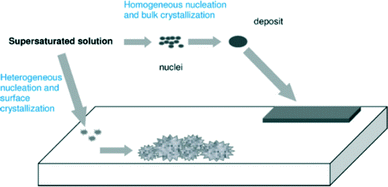 | ||
| Fig. 2 Pictorial depiction of scale formation.5 | ||
The steps involved during scale formation are shown in Fig. 3.
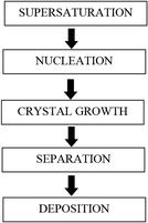 | ||
| Fig. 3 Steps involved in scale formation (adapted from Beruto and Giordani12). | ||
Nucleation and crystal growth take place during precipitation. There must exist minute particles, nuclei or seeds in a solution for the development of crystals. These seeds serve as crystallization sites. Nucleation is usually achieved through agitation, seeding, mechanical shock, etc.13 Nucleation can be initiated by various means (see Fig. 4).
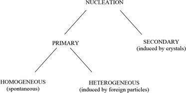 | ||
| Fig. 4 Simple scheme of nucleation.13 | ||
It can be achieved by the formation of unstable clusters of ions from the saturated solution; this process is referred to as homogeneous nucleation as shown in Fig. 5.
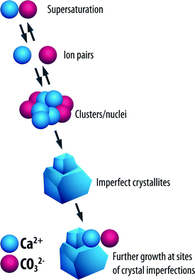 | ||
| Fig. 5 Process of homogeneous nucleation.2 | ||
These clusters go on to form seed crystals due to shifts in the equilibrium ion concentration. Growth of the seed crystals occurs by adsorption of ions onto the imperfections on the surfaces of the crystals. A newly formed seed crystal will either increase in size or redissolve in a supersaturated solution; the path that the seed crystal follows depends to a very large extent on its size. Growth or dissolution of the seed crystals results in the reduction of the specific Gibbs free energy, ΔG, of the particles.2,13
When nucleation proceeds as the result of seeding entrapped in cavities such as foreign bodies or the walls of the vessel containing the solution, this is termed heterogeneous nucleation (see Fig. 6).
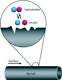 | ||
| Fig. 6 Process of heterogeneous nucleation.2 | ||
Heterogeneous nucleation tends to occur on the fluid–boundary interface such as those rough surfaces on pipes, perforations, joints or seams.2
4. Water hardness
Water hardness comes from the reaction between multivalent cations (e.g. Ca2+ and Mg2+) and anions (e.g. HCO3−, CO32− and SO42−) in solution. Calcium and magnesium cations are the main culprits in hard water formation. The solubility of these salts decreases with temperature. Table 2 shows a grouping of water by concentration of dissolved salts and degree of hardness.| Concentration (as ppm CaCO3) | Hardness level |
|---|---|
| 0–75 | Soft |
| 75–150 | Moderately hard |
| 150–300 | Hard |
| 350 and above | Extremely hard |
Calcium carbonate is one of the most common forms of scale3,4 and is the subject matter of this work; ergo, more focus will be devoted to it. The formation of calcium carbonate hard water is depicted by the equations below:
| CO2(aq) + H2O(aq) ⇌ H2CO3(aq) | (1) |
| H2CO3(aq) ⇌ H+(aq) + HCO3−(aq) | (2) |
| CaCO3(s) ⇌ Ca2+(aq) + CO3−(aq) | (3) |
| H+(aq) + CO32−(aq) ⇌ HCO3−(aq) | (4) |
| Ca2+(aq) + 2HCO3−(aq) ⇌ Ca(HCO3)2(aq) | (5) |
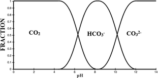 | ||
| Fig. 7 Carbonate equilibria.15 | ||
Since calcium carbonate displays inverse solubility, its precipitation and deposition would increase with the rise in temperature.3 The process of calcium carbonate scale formation, though widely observed and reported, is indeed complex and not fully understood.11
5. Calcium carbonate and its crystalline phases
Calcium carbonate occurs in three anhydrous crystalline phases or polymorphs (aragonite, calcite and vaterite), two hydrous phases (monohydrocalcite, ikaite), and amorphous calcium carbonate (ACC). The stability of the polymorphs of calcium carbonate in ascending order is given in Fig. 8.Calcite and aragonite are the most common phases of calcium carbonate.16–20Calcite has a trigonal–rhombohedral crystalline structure and is the most thermodynamically stable phase of calcium carbonate.21,22 It is usually associated with hard tenacious scale.
The aragonite's crystal structure is orthorhombic. It forms soft non-adherent scale that is easily removed by fluid flow.
In accordance with Ostwald's step rule,23 the least stable polymorph will emerge first during the crystallization of calcium carbonate from solution. Generally, the phase that is least dense is first precipitated and then it keeps morphing into the next dense phase, till it modifies into the densest phase, which is the phase with the highest stability.22
6. Orthodox means of scale removal and prevention
The most frequently used and cheapest method employed is the chemical technique. Hydrochloric acid is usually used in dissolving carbonate scale which has high solubility in acids. Other types of scale which are not very soluble in acids, for example hard sulfate scale, can be removed by introducing chelating compounds which enclose and restrict scale cations within their closed ring structure.24Scale removal is also achieved through mechanical means such as milling and drilling for very hard and thick scale, by means of explosives which send shock waves and are able to break brittle scale.2 These mechanical methods, although effective, sometimes require an inordinate amount of time and effort.3 They also cause the damage of the walls of vessels and pipes, thereby creating more sites for heterogeneous nucleation.
Conventional methods of preventing scale build-up include ion exchange, pre-precipitation of the salt with lime or soda ash and addition of scale inhibiting agents. Ion exchange makes use of ion exchange resins which simultaneously entrap scale forming ions and release non-scale forming ions into water (see Fig. 9).
Scaling is usually inhibited by threshold scale inhibitors which are mainly phosphate compounds.2,25
These chemicals are expensive, alter the solution chemistry, are unsuitable for human consumption and could be harmful to the environment causing undesired effects such as eutrophication and algal blooms.11,25
7. Magnetic fields as an alternative to scale treatment
Alternative approaches to ameliorating scale build-up should definitely be encouraged. One approach is the use of magnetic fields (MF). This has been in use for quite some time, as a matter of fact for more than a century, and quite a number of patents for magnetic scale treatment devices have materialized. As far back as the 1800s, patents were issued in the United States for MF anti-scaling equipment by Porter in 1865,6 Hay in 1873,26 and Faunce in 1890.27 In 1945, another MF scale treatment instrument was filed for a Belgian patent.28 More than a half-century later, yet another patent for scale treatment by MF was issued in the United States, this time by Janczak and Krensel.29 In USSR, strong electromagnets have been employed in heating set ups since the middle of last century.30 The application of MF was reported in the United States since 1975.30,31 The magnetic field is produced by either permanent magnets or electromagnets in various configurations.Despite being in use for decades, the process still remains in the area of doubts and uncertainties.32 MF treatment has a long and debatable history33 and has been reported as being effective in most cases.3,34 Although there has been a huge rise in the quantity of magnetic water treatment devices, which at mere glance could indicate the efficacy of these devices in scale control, the evaluation of the effectiveness of these devices in treating scale is highly disputable.35,36 There have been instances whereby MF treatment has been reported to be ineffective and the precise explanations for this inefficiency are vague.1 There are numerous reports on the effects of magnetic fields in various applications. The observed magnetic effects have been attributed to a number of possible mechanisms. Experimental work is often reported where no details governing physicochemical conditions are listed, so the claims made can be easily refuted, creating controversy as to the efficacy of the process.37 There was no conclusive verdict on the changes in physicochemical properties of water when six different permanent magnetic instruments were used to treat water.38 These phenomena are not explained by electromagnetic principles and have often been perceived as unreliable and strange.39 These discrepancies seem to have been caused by the use of different methods of producing a MF, by the use of alternating MFs, and by using water containing different types and levels of impurities.40 There are also cases where all the operating conditions are not disclosed and thus leave the procedures applied open to conjectures. The reported water treatment methods are sometimes questionable due to lack of consistency and reproducibility.41,42 The mechanism(s) involved in MF treatment is very complex.43 Poor reproducibility of laboratory and industrial trials35 has done little to encourage wide acceptance of these devices. One interesting paper shows a successful commercial application of MF water treatment on a large scale in Poland. In this work, Szkatula et al.41 implemented MF treatment on industrial water scaling in 25 kW heat exchangers and a 1 GW power plant with an observed reduction in scale formation. Whatever scale deposits that formed were analyzed using particle-induced X-ray emission, X-ray diffraction, electron microscopy, infrared spectroscopy and chemical techniques. The scale samples from the heat exchanger with blank treatment comprised mainly calcite. By contrast, in the heat exchangers where MF treatment was applied, calcite formation seemed to have been halted and the deposits primarily comprised soft materials reported to be colloidal silica. Hence, calcite growth was retarded in favor of colloidal silica onto which Ca2+, Mg2+, as well as other scale forming cations are adsorbed followed by precipitation in the form of coagulated agglomerates. The authors linked this effect to a rise in cation concentration in the negatively charged silica adsorption layer caused by destabilization of the diffuse layer instigated by Lorentz forces – a mechanism that has been touted by numerous researchers,43–46 but has also had its share of criticism.47,48
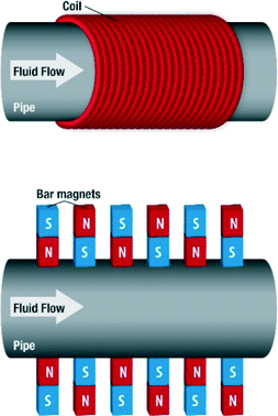
The magnetic devices used in MF treatment are generally made up of either permanent magnets or electromagnets (Fig. 10).
Obviously the field strength is expected to vary with the number of coils or the thickness of the wire used in the electromagnets. Where permanent magnets are used, the arrangement varies also. Some are arranged with alternating poles of magnets, while some are arranged without alternations. The number of permanent magnets also varies. The sole aim of any of the configurations is to produce a magnetic field within the conduit where the fluid passes through. These devices can be home-made or designed and built by manufacturers. Manufacturers usually have specifications for their devices, ranging from the location on a piping system to the flow regime. In addition, the magnetic field generated could be static or pulsating, orthogonal to fluid flow or generated in the direction of fluid flow. In considering the studies that have been carried out by researchers pertaining to MF water treatment, the type of device, field type and strength as well as other relevant details will be signified, if possible.
8. Observed effects and possible mechanisms
Application of magnetic treatment to water still remains a controversial topic49,50 and the various effects and mechanisms are still obscure – at the very best, not fully understood. At the moment, there is no unified verdict on the mechanism under which this method of water treatment is executed.1,11,47 There have also been other claims of MF treatment, aside from anti-scaling.51–56 A number of effects, factors and mechanisms pertaining to MF water treatment and its anti-scaling effects are discussed.8.1. Surface tension
The interfacial interactions between water molecules and scale forming ions could be an important step in scale formation. Changes in the surface tension of water have been reported by some authors, while others note negligible effect of MF on water surface tension.The increase in the surface tension of water after MF treatment has been reported by Fujimura et al.57,58 The authors postulated the stabilization of the hydrogen bonds in water by MF treatment as an explanation for this effect.
In tests carried out by some researchers, the refractive index of water was found to have increased after MF treatment, indicating a probable higher surface entropy of water which also causes a greater surface tension.59 They explained that MF, which produced a higher electron delocalization of the molecules of water, resulted in stabilization of the hydrogen bonds. A molecular dynamics simulation by Chang and Weng60 buttressed this point by showing that MF produced water stabilization by strengthening the bonds between the water molecules.
By contrast, the surface tension of water has been observed to decrease after treatment with the magnetic field. Cai et al.61 subjected water at a velocity of 1 m s−1 to a stationary magnetic field of 0.5 T. Their tests revealed a reduction of surface tension with water and they linked this observation to a decrease in molecular energy and formation of new hydrogen bonds due to MF treatment. Amiri and Dadkhah62 also observed a reduction in surface tension; however they attributed this reduction to impurities in the water and not MF. The authors concluded that surface tension of water is too sensitive to experimental conditions to be considered as a safe and reliable indicator for the study of the effects of magnetic field on water.
Surface tension can be expressed as the surface energy per unit area. The surface energy at the interface of water molecules and a glass tube is larger than that between water–water molecules. An increase in the number of colloidal particles, however, increases the surface energy at the water molecule–colloid interface, thus decreasing the surface energy at the water molecule–glass tube interface. Cho and Lee63 subjected water (untreated tap water & natural tap water) to MF treatment using a permanent magnet and also a solenoid coil. There's an observed reduction in the surface tension with an increase in the number of circulation through the devices. The authors go on to observe a greater reduction in the surface tension of the natural hard water passed through the solenoid coil, inferring that the water hardness may affect the efficiency of the solenoid coil device. They eventually proposed that there could have been an increase in the fraction of the collision of ions that led to bulk precipitation.
The authors also performed a dye injection experiment and noted that the dye drop spread radially in an untreated water sample, whereas the dye drop fell more quickly in the samples treated with MF, with a faster fall observed in the samples that were passed longer through the solenoid coil. A reduction in surface tension was proposed as the reason for the observation (see Fig. 11).
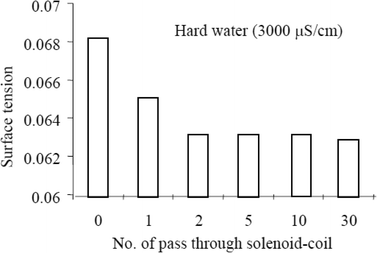 | ||
| Fig. 11 Surface tension reduction with MF treatment.63 | ||
The authors explain that MF treatment causes a faster collision frequency of the ionic species in water therefore producing large precipitates and that more MF treatment produces an increase in the size and quantity of particles which manifest in a reduction in the surface tension of water.
Corroborating results were obtained using permanent magnets.64 Cho et al.65 indicated that decrease in surface tension correlated with a reduction in fouling-resistance results.
Amiri and Dadkhah62 fed tap and pure water through a magnetic conditioner (a minimum strength of 0.385 T). They observed a reduction in surface tension, and also it reduced further with the frequency of treatment. The authors also observed that surface tension of the treated water was not constant with time (gradually increased) while that of the untreated sample (pure water) was virtually stable with time. They concluded that impurities from plastic pipes resulted in the reduction in surface tension and not the MF per se.
Gruber and Carda66 reported that there were no alterations in the physical (surface tension inclusive) and chemical properties of water when water was treated with permanent magnets with the MF orthogonal to the fluid flow.
There could be a number of reasons for the differing results obtained by these authors; they range from impurities, temperature, treatment time, dissolved gas content, and many more.
8.2. Zeta potential and diffusivity
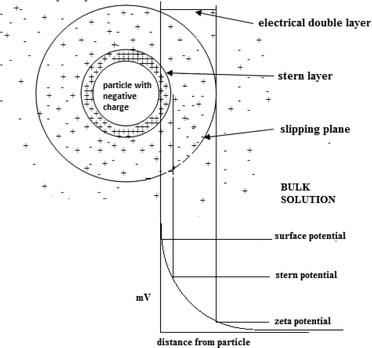
Zeta potential is a key parameter that characterizes the electrochemical equilibrium on interfaces. It is the potential difference within the electrical double layer (i.e. the neighborhood between the surface of the negatively charged particle and the bulk solution) of a particle in solution (see Fig. 12).The stability of a colloidal system is indicated by the value of the zeta potential. Large values (on the negative or positive side of the scale) result in repulsion between the particles therefore prohibiting coagulation. However, zeta potential values close to zero suggest coagulation of the particles.
Gamayunov67 proposed a model on the probable effect MF could have on the electrical double layer, which offers an explanation on the mechanisms of MF water treatment regarding particle coagulation and crystallization. He postulated that, under the influence of MF, Lorentz forces are generated which displace charged particles, consequently causing a redistribution of the charges in the vicinity of the electrical double layer with an adjustment of the Stern potential. These changes can be detected by zeta potential measurements and have been reported by a number of researchers.
Parsons et al.37 performed a series of tests in which he observed a 16% decrease in the zeta potential of calcium carbonate particles suspended in solution after exposure to MF.
They also observed that the levels of calcium in the solution played a role in the magnitude of the reduction in zeta potential. From their observations, the authors draw a conclusion that MF may have an effect on colloidal stability which in turn could point at the decrease in the charge density in the vicinity of the Stern layer.
They further noted that the observation may also be a direct or indirect effect or possibility, since the surface charge of a species is dependent on a number of factors such as ionic strength and solution pH. Zeta potential reduction of calcium sulphate and calcium carbonate after MF exposure was also reported in another work by the same authors.68
Gehr et al.69 showed that suspensions of calcium sulphate placed in an NMR spectrometer generating a field strength of over 4 Tesla (T) caused reductions in a surface charge of approximately 25%. They also observed changes in the levels of suspended and dissolved solids.
Crystal growth on already formed scale is favourable thermodynamically.70 Accordingly, a way MF could bring about scale prevention is by modifying the particle size and surface charge of burgeoning seed crystals thus achieving reduced proclivity for the deposition of particles on walls.1
Higashitani et al.71 also reported that the magnetic exposure reduces the zeta potential and diffusivity of colloids. They went on inferring that the magnetic effects on the zeta potential are very similar to those on the coagulation rate. A number of authors carried out observations and put forward the idea that a drop in the zeta potential of CaCO3 particles leads to the destabilization of the species, consequently leading to aggregation, and ultimately increasing the rate at which sedimentation occurs.72,73 This is in accordance with the results of the study by Parsons et al.,68 who observed that, upon MF treatment, the produced aggregates were larger in size and more abundant. It has been alluded that magnetic exposure effects on colloidal solutions do exist, even if the colloids are non-magnetic and the magnetic field is of low flux density and the effects can be attributed to a conformational change in water molecules, ions or hydrated ions adsorbed onto the particle surface.74,75
There are however reports that suggest MF has no influence on the zeta potential of particles in water.48
A very recent study on assessing the Stern layer of calcite using visual techniques by atomic force microscopy could assist in shedding more light on the proposed models.76
8.3. Conductivity
Magnetic fields could bring about changes in the conductivity of electrolyte solutions as well as in the volume of evaporated water from the solutions. These effects are dependent on the nature of the ions present in the solutions and are proportional to the thickness of the hydration shell around the ions and the thermodynamic functions of hydration. It is proposed that exposure of water to MF results in alterations in the hydrating structure of water in the vicinity of the ions.77 Szcze78 found that the MF causes a reduction in the conductivity of water which has an inverse relation with fluid flow. He also noted that MF treatment produced a greater amount of water evaporation before and after the distillation of water. These observations were attributed to strengthening of the hydrogen bond structure and a disturbance of the gas/liquid boundary due to formation of minute gas bubbles. Lee et al.40 conducted a series of tests by recirculating partially outgassed deionized water in a closed loop and subjecting it to magnetic exposure (permanent magnet, 1 T) while monitoring the conductivity. They recorded interesting changes in the conductivity which fluctuated as the magnetic treatment was administered and withdrawn from the flowing liquid: a drop in conductivity in the former case and a rise in conductivity in the latter one. Fig. 13 shows representative results of their tests.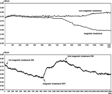 | ||
| Fig. 13 Conductivity changes in MF treated and blank partially outgassed water.40 | ||
There are disputable reports on the conductivity changes caused by MF treatment of water.79–81 Some reports claim that the conductivity of water is increased by MF,79 some claim that MF slows down the rate of conductivity decline of hard water,82 and other reports suggest MF decreases the conductivity of water.78,83 The contradicting reports seem to be a result of the application of MFs of different configurations as well as water with varying constituents and concentrations.
8.4. Bulk precipitation and coagulation
Quite a number of researchers have provided reports regarding the influence of MF in the production of precipitates with altered crystallization patterns, which encourage bulk precipitation of crystals rather than adhesion to walls of pipes and vessels.The results of an approach to handle the hardness ion effect on bitumen extraction have been described by Amiri.84 The author reported that bitumen recovery in the extraction operation can be enhanced by performing magnetic treatment of water. MF was found to prevent Ca2+ and Mg2+ ions from taking part in the hetero-coagulation process, which in turn resulted in increased recovery.
Alimi et al.85 showed that the magnetic treatment decreases the solubility of CaCO3 and promotes its precipitation in the bulk solution rather than on the reactor walls. This effect depends on the solution pH, the flow rate and the treatment duration. MF increases the frequency of collision between calcium and bicarbonate ions, thereby favoring precipitation and agglomeration in the solution.1
Inconsistent results have been reported on the effects of MF on coagulation rates. Higashitani et al.72 conducted tests by individually treating static colloidal dispersion of ultrafine polystyrene latex and electrolyte solutions with MF (produced by an electromagnet), followed by mixing of both solutions after a preset stand time. Coagulation rate readings were measured using a nephelometer. The authors reported a 10% reduction in the coagulation rate at magnetic field strengths greater than 0.4 Tesla (T) and exposure time above 10 minutes. They also noted that the effects persisted even 6 days after the magnetic treatment was completed. This observed reduction in the coagulation rate was greatest in the mixture of both colloidal and electrolyte solutions, followed by the effects observed for the colloidal solutions only, the poorest effects being recorded in the electrolyte solutions. The coagulation rate depended on the magnetic treatment time, the magnetic field strength, the particle size and the ionic content of the solutions. It was proposed that the magnetic treatment resulted in the modification of the water molecule structure, as well as the adsorption of ions on the particle surface.
Duffy reported the magnetic effects on the coagulation for suspensions of iron.34 Disparate results were observed at different pH levels: first an increase in coagulation at a pH of 5.15, and then a decrease at 5.85–6.00. The MF strength used was 0.06 Tesla (T). The author labels the experimental error as the explanation for the varying results/effects.
Tombacz et al.86 also exposed suspensions of iron to MF of 0.1 Tesla (T) at a pH of 4.2 and in this case observed an increase in the coagulation rate.
Fathi et al.87 performed experiments to ascertain the scaling potentiality of MF (a strength of 0.16 Tesla) treated water by inducing calcium carbonate precipitation utilizing the extraction of carbon dioxide gas. The authors pointed out that electrochemical precipitation tests could cause a strong interfacial shift, which would result in mainly heterogeneous nucleation. They stated that this method of precipitation is different from what occurs in actual systems where homogeneous and heterogeneous precipitations are caused by the escape of CO2 gas from water as a result of pressure change or a rise in temperature. Their results show that the amount of precipitate increased with exposure time to MF and that homogeneous precipitation was favored. The homogeneous precipitation comprised mainly aragonite and calcite crystals, two polymorphs of CaCO3. Their test waters contained no calcium carbonate seeds.
8.5. Adsorbed layer thickness
Similar to the effects of MF on zeta potential, reports have circulated on MF influence on the adsorbed layer of particles in solution. Changes in the adsorbed layer thickness could cause a change in the pattern of seed nuclei formation and crystallization of precipitates from solution.Higashitani et al.39 reported the effects that MF exposure with a field strength of 0.42 T had on the thickness of the adsorbed layer in aqueous solutions measured with an atomic force microscope. Electrolyte solutions of 0.0001 kmol m−3 concentration were prepared by dissolving chlorides of Li+, Na+, K+, Rb+, and Cs+ in pure water (17.3 MΩ cm resistance) placed in a water bath at the temperature 25 °C ± 0.5 °C. It was noted that the thickness of the adsorbed layer of KCl solutions increased with exposure and reached a constant value from 20 minutes upwards. They also noted that the magnetic effect was still observed 24 hours after the MF exposure.
Upon the addition of methanol to the electrolyte solutions, a reduction in the thickness was observed with an increase in methanol concentration which led the authors to infer that the MF treatment is linked with the properties of water molecules. A similar observation was made when the solutions were heated to a temperature of 30 °C and above.
In order to test for the role of ions on the MF induced adsorbed layer thickening, solutions of Li+, Na+, K+, Rb+, and Cs+ were exposed to MF and the effects were compared. The comparison showed that thickening was recorded in solutions of K+, Rb+, and Cs+ (which are structure-disordering ions), while the effect of MF on the thickening of the adsorbed layer in Li+ and Na+ (which are structure-ordering ions) solutions was imperceptible.
The thickening of the adsorbed layer causes a reduction in the coagulation rate which is more pronounced for particles of smaller sizes, since the role that the solvent/structural force plays strengthens as the size of particles reduces. In addition, the ostensible increase in size of the particles (due to the thickening) causes a reduction in diffusivity. Accordingly, a reduction in the zeta potential and surface potential will occur due to the outward projection of the slipping plane further from the solid surface.39 Based on the results obtained, the authors surmise that the thickening of the adsorbed layer is due to the adsorption of structured ions, brought about by MF quasi-stabilization of water molecules in the vicinity of the ions.
The ions responsible for scaling may be modified such that their adsorbed layers thicken and larger particles are precipitated out of solution.
8.6. Temperature
Temperature does affect scaling, with an increase in temperature causing a faster rate of scaling. But the interactions of MF with temperature on scaling are unclear with different accounts of the impact of MF treatment on temperature and vice versa.Parsons et al.37 carried out experiments to determine the effect of temperature on the formation of calcium carbonate in a recirculatory test rig made up of a PVC pipe network and a copper heat exchanger. Calcium carbonate solutions prepared by mixing calcium chloride and sodium bicarbonate in 15 mΩ pure water were treated with electromagnetic fields with a strength of 7000 gauss supplied by a non-intrusive electromagnetic device. The Ca2+ concentration varied between 250 and 400 ppm; the initial pH was 8 and the flow rate of the solutions in the test rig was 12 L min−1. Scale was deposited on the surface of the heat exchanger at temperatures preset at between 40 °C and 60 °C.
The time needed for calcium concentration to drop to half of its initial concentration was measured over the temperature range. It was discovered that higher temperatures favor a faster scaling rate of calcium carbonate but the effect of the MF treatment was not perceptible; in other words, there was no apparent difference in the treatment with and without MF within the temperature range.
Higashitani et al.39 on the other hand observed thermal dependence of MF treatment on electrolyte and colloidal solutions. Firstly, an observation was noted on how the MF effect is not noticeable at temperatures below 25 °C, but at temperatures above 30 °C the magnetic effect does wane as the temperature increases and almost disappears at 50 °C. Similar thermal disruptions of magnetic effects on solutions were observed for the fluorescence emission intensity in solutions with dissolved fluorescent probes.74
8.7. Supersaturation
Parsons et al.37 performed tests to determine the outcome of varying calcium carbonate concentrations on the efficacy of MF treatment. The concentrations were in the range 250–400 ppm. They concluded that the degree of magnetically induced change is dependent on solution concentrations reaching a maximum at 350 ppm. There is an increase in the number and size of crystals at high calcium ion solution concentrations.88 This is in concordance with the report by Chen et al.,89 which states that at higher super saturation levels, crystal nucleation and growth are accelerated. The efficiency of MF treatment increases with hardness of water.87Donaldson and Grimes,3 on the other hand, reported that at very high levels of super-saturation, anti-scale magnetic treatment became ineffective.
8.8. Exposure time to magnetic field
Fathi et al.87 performed precipitation tests to determine the impact MF exposure time had on hard water (prepared by dissolving calcium carbonate in deionized water and bubbling CO2) with concentrations between 300 and 500 mg L−1. The MF treatment was carried out by circulating 0.5 L of the prepared hard water through a closed loop made of a glass tank and plastic pipes, to which a magnetic device was attached (a field strength of 0.16 T), comprising 5 pairs of permanent magnets arranged with alternating poles and inserted in a casing made of iron. After the treatment, the water was placed in a cell inserted in bath which regulated the temperature at 30 °C. Precipitation was induced by ridding the water of CO2 by bubbling nitrogen gas through the bottom of the cell. pH and conductivity measurements were periodically taken to pinpoint the nucleation time. Water samples were periodically analyzed for calcium ion concentrations and after the precipitation exercise the water was filtered and the mass of the filtrate was measured to detect the homogeneous precipitation (which was obviously caused by homogenous nucleation). A notable increase in homogeneous precipitation was observed with increase in magnetization time, suggesting that higher exposure times favor the conditions for increased homogeneous precipitation of calcium carbonate crystals. The authors concluded that the efficiency of MF treatment increases with time of exposure to the MF. In addition, a study conducted by Knez et al.48 demonstrated that the preferential precipitation of aragonite has a direct relationship with the magnetization time. Agreeably, tests conducted by other researchers established the preferential precipitation of aragonite with increasing exposure times to electromagnetic fields.90 Nevertheless, low exposure times supported the formation of a different crystalline phase of calcium carbonate in the form of vaterite.The effect of MF exposure time on the precipitation of calcium carbonate polymorphs was also studied by Tai et al.91 The researchers noticed that the yield of each polymorph was dependent on the MF exposure time, with aragonite being the most abundant crystalline phase.
Likewise, Higashitani and Oshitani39 noted that the thickness of the adsorbed layer in a KCl solution (10−4 kmol m−3) increased steadily with MF (0.42 T produced by a permanent magnet) exposure time and remained constant above 20 minutes of exposure time. In another work, Higashitani et al.74 also noted a time dependent behavior of the fluorescence emission intensity of solutions of fluorescent probes with long alkyl chains. The observed MF effects increased with MF exposure time and attained a steady value above 30 minutes.
Similarly, a reduction in zeta potential with increasing exposure time was recorded when solutions of potassium chloride and calcium chloride were each treated with MF of 0.56 T field strength.
8.9. Nucleation rate
Madsen92 precipitated calcium and manganese(II) carbonate, phosphates of magnesium, calcium, iron(II), cobalt(II) and zinc, and calcium oxalate and sulfate at 25° C in a magnetic field of 0.27 Tesla (T). The only perceptible changes caused by MF were observed in phosphates, carbonates and diamagnetic cations. In the presence of MF, there were noticeable increases in the nucleation rate and crystal growth. The mean crystal size however reduced. For the calcium carbonate precipitation, static solutions of calcium chloride and sodium carbonate were treated in the MF. The authors label proton spin inversion as the reason for their observations. It causes an increased migration rate of protons from the hydrogen phosphate and hydrogen carbonate ions to water. Wang et al.93 reported that under certain conditions in the presence of an external MF, the nucleation rate can be greatly increased. This conclusion is based on the observation of fast homogeneous precipitation which can be measured as the incident light scattering commonly referred to as the Tyndall effect.The authors, employing turbidity measurements, reported that in the presence of a MF of 0.8 Tesla (T) the precipitation rate of calcium carbonate increased (i.e. crystallization rate increased) and the crystal size reduced. Due to the increased precipitation rate in the MF, the crystals formed are more abundant and they are smaller in size.
Higashitani et al.73 also carried out investigations on the impact that magnetic treatment had on calcium carbonate formation. They however noted an increase in particle size and a reduction in the nucleation rate of calcium carbonate when quiescent-filtered solutions of calcium chloride and sodium carbonate were treated with MF of 0.3 Tesla (T) for more than 10 minutes before mixing. The authors associate the effect primarily with the magnetic treatment of the sodium carbonate solution before the mixing. They also noted a memory effect that lasted for as long as 5 days.
The results of Parson et al.68 show an initial magnetically induced increase in particle size and numbers in solution, although this trend changes with time as the larger particles settle out.
Particles with larger sizes possess lower surface charges and thus display a lesser tendency to stick to vessel or pipe walls, therefore reducing scaling.94
Going by an approach espoused by Nielsen, the nucleation rates are lowered tremendously upon MF conditioning. Eqn (6) ties the nucleation rate, particle number and time and is expressed as:
| J = N/t | (6) |
The total particle count and nucleation rate are related by eqn (7) below:
log![[thin space (1/6-em)]](https://www.rsc.org/images/entities/char_2009.gif) N = 2 + (3/5)log N = 2 + (3/5)log![[thin space (1/6-em)]](https://www.rsc.org/images/entities/char_2009.gif) J J | (7) |
Sohnel et al.,36 observed that MF had a negligible effect on the rate of homogeneous nucleation. The strength of the MF used in their work was 0.5 T. The authors arrived at the conclusion that MF is incapable of causing changes in the nucleation rate and growth of crystals because the phenomenon was neither supported nor explained by the crystallization theory of the time.
In contrast, another report showed a decrease in the nucleation rate of calcium carbonate from calcium bicarbonate solutions caused by electromagnetic fields with field strength as low as 0.03 Tesla (T). The slower nucleation rate resulted in the precipitation of larger crystals.96 The authors conceptualize an alteration of the charge density at the liquid/solid boundary of the seed nuclei brought about by MF polarization (see Fig. 14).
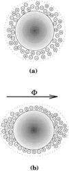 | ||
| Fig. 14 (a) Nuclei with uniform charge density. (b) Charge density modified by MF.12 | ||
8.10. Effect of pH
Parsons et al.68 conducted experimental runs to evaluate the efficacy of orthogonally generated MF on calcium carbonate scale formation in solutions under controlled pH conditions. The authors made use of a test rig comprising PVC pipes, a pump (15 L min−1 flow rate), a heat exchanger, a cooling unit, and a non-intrusive electromagnetic device with a field strength of 0.2 T. The temperature of the heat exchanger was set at 60 °C while the cooling unit was set to reduce the temperature of the flowing solution to between 28 and 30 °C. Three different tests were carried out. The first two systems comprised solutions with preset pH of 8.0 and 8.5 which were regulated with 0.1 NaOH solution; the last scenario was executed without pH adjustment. For obvious reasons, non-treated tests were performed for comparison to MF treatment outcome. Calcium carbonate solutions (300 ppm) were prepared by reacting calcium chloride with sodium bicarbonate in deionized water. The amount of scale formed on the heat exchanger was quantified by dissolving in dilute hydrochloric acid followed by titration. From the results obtained, there was no significant effect of MF on the solutions, in which the pH values were regulated, though the rate of scaling increased. On the other hand, a 48% reduction was observed in the case where there was no pH adjustment. In addition, during the MF treatment of the unregulated system, the pH fell from an initial value of 8 to 7.5 and then rebounded to the initial value as the experiment approached the end. This led the authors to the conclusion that MF treatment is dependent on the pH regime of a solution and is ineffective when the pH is regulated. Although the effect of MF on scaling was negligible when the pH was regulated, an interesting observation was made by the researchers. They noted that MF treatment seemed to have an effect on the physicochemical properties of the pH-regulated system. This was deduced by the amount of NaOH required for pH regulation for the magnetically treated system which was as high as 2.5 times that required for the same purpose in the untreated system.A number of research studies have shown variations in pH levels caused by MF treatment. Unlike the study by Parsons et al.,68 there was no regulation of the pH in the studies. Firstly, we consider situations in which pH reduction was noted such as in the study by Busch et al.,97 where a decrease in pH from 7 to 6.5 and then an increase to a pH of 8 was noted. The authors suggested that Lorentz forces produced electric currents that caused electrochemical reactions, which eventually resulted in pH changes. A different set of researchers also observed a pH decrease from 9.2 to 8.5 when MF treatment was applied to solutions of calcium hydroxide.98 The authors also recorded MF effect dependency on pH levels, with promotion of calcium carbonate precipitation at pH levels lower than 9 while stifling occurred at pH values higher than 9.3.
Scale reduction may be attributed to pH decrease for systems treated with MF, since small pH changes will cause shifts in the carbonate equilibrium as shown in Fig. 7. It has been documented that a unit pH increase is capable of resulting in a faster rate of scaling than an 80 °C temperature rise.99
Secondly, in contrast to the above reports, there have been instances where declining pH of systems upon MF treatment of synthetic raw water was shown under static100 and flow97 conditions. The pH changes were linked to outgassing of the solution. A different study showed fluctuations in pH of distilled water as a result of MF treatment,101 while another work reported an opposite behaviour.102
8.11. Fluid flow rate – velocity
Tests conducted by Parsons et al.68 with a magnetic field strength of 0.7 Tesla (T) revealed that no velocity dependency of the magnetically induced changes on the scaling rate was apparent with flow rates of 1–2 m s−1. The small deviations noted could be attributed to the increased shearing. Previously conducted tests found that scaling was consistently dependent on the flow rate through an intrusive magnetic treatment device,1 whereas further studies have shown that the turbulence created by the device itself contributed more to the observed effects on scale formation than the magnetic field.86Fathi et al.87 observed that water flow in a pipe network tends to stimulate nucleation of calcium carbonate from solution, even without the application of MF. The authors report an improved efficacy of the MF application with an increased flow rate in the pipe and also with MF application time.
Shahryari et al.103 observed a difference between the appearances of the scale accumulated on the heat-exchange surfaces from cooling water. At a velocity of 0.5 m s−1, the authors obtained a thick layer of deposits when there was no MF application. The observed scaling however decreased when the flow velocity was increased with the minimum scale formation detected at a flow velocity of 1.3 m s−1. On subjecting the cooling water to MF treatment, the scale deposited on the heat exchanger surface assumes a much thinner and less adhesive form which is easier to clean off. There was no considerable change in the scale formed at a water velocity of 0.8 m s−1 but, when the flow was raised to 1.3 m s−1, the scaling was reduced to the point that the researchers described the heat exchanger surface as clean and scale-free. Knez et al.48 however discovered that fluid velocity played an insignificant role in the magnetically induced precipitation of aragonite from calcium bicarbonate solutions. This is opposing to the magnetohydrodynamic principle that has been put forward by some authors, linking the fluid flow through a magnetic field as the mechanism of operation.69,86
8.12. MF effects on polymorphism of calcium carbonate
Changes in calcium carbonate crystallization behavior triggered by the application of magnetic fields have been reported.3,82,95,104–106 The efficacy of MF treatment is often being attributed to the precipitation of a less stable phase of calcium carbonate (usually aragonite), which is thought to form less tenacious layers that can be easily washed off a substrate by fluid flow.The formation of scale comprises, amongst other steps, nucleation followed by crystal growth, whereby the former initiates scale formation on a virgin surface, while the latter is responsible for further scale deposition. Therefore, the process by which calcium carbonate crystallizes out of solution is a crucial step in drawing closer to deciphering the MF treatment scale controlling phenomenon.45
In a study conducted by Parson et al.37 crystal morphology and proportion were altered by MF application, although there was no quantitative report of the changes. A greater number of aggregates and changes in the appearance of the calcite formed in solution and on the heat exchanger were reported. They also noted a greater number in particle size for which the aggregation of individual crystals was identified as the main mechanism for the enlarged particle size.
As they conducted experiments under different conditions, the appearance of the aggregates and morphology of the crystals were altered. The authors basically observed three crystalline forms of calcium carbonate, first of which is calcite, detected in the scale formed from MF treated and blank solutions. The calcite crystals made up most of the scale deposited and were present in MF treated specimens. Spherical shapes of calcite were observed and were credited to non-uniform crystal growth of the nuclei induced by MF treatment. The scale formed on the heat exchanger surface was determined to be calcite at operating temperatures below 60 °C, and the spherical morphology was once again observed when MF was applied to the solutions.
The second crystalline phase observed is aragonite, which precipitated on the heat exchanger surfaces at temperatures higher than 60 °C. This time around, there were not any deformations in the crystal morphology; however, the sizes of the crystals were notably greater in the MF treated specimens than those in the untreated samples.
Lastly, vaterite was found to be present exclusively in the storage vessel after MF treatment.
Aragonite, which may emerge from the transformation of metastable vaterite, has a typical morphology that is needle shaped and it displays a weak tendency to adhere to a surface. It usually forms soft non-adherent deposits that are easily removed by fluid flow.90,107 Vaterite has also been reported to give soft non-adherent scale.108
On the other hand, calcite, which is the more stable crystalline phase of calcium carbonate at room temperature,109 produces very thick and tenacious scale which proves problematic to be removed by mechanical means.11
In a study organized by Fathi et al.87 the authors found out that the calcium carbonate crystals precipitated in the absence of MF exhibited the widely known morphology of vaterite, which was confirmed by XRD and Raman spectroscopy techniques. The authors noticed, however, that the crystals generated after MF application were mostly of the calcite form. They concluded that MF favors the homogeneous precipitation of calcium carbonate in the calcite and aragonite crystalline phase ahead of vaterite.
Knez et al.48 discovered that the precipitation of aragonite from calcium bicarbonate solutions was facilitated by magnetically treating the solutions. SEM and XRD analysis of their precipitates are shown in Fig. 15 and 16.
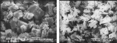 | ||
| Fig. 15 Micrographs of calcium carbonate precipitates. (a) No MF treatment. (b) MF treatment.48 | ||
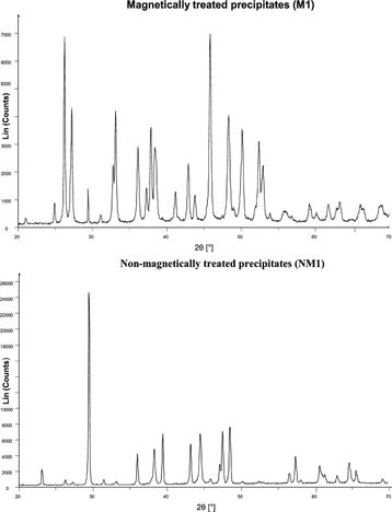 | ||
| Fig. 16 XRD spectra of calcium carbonate crystals from MF and non-MF treated solutions.48 | ||
The authors rebuffed the influence of magnetohydrodynamics (which is a consequence of Lorentz force) on the charge distribution as a possible mechanism, but rather proposed that the transformation in the calcium carbonate phase was induced by MF interaction with the polymorph phase equilibrium. The hypothesized mechanism involved either the carbon dioxide/water interface or the hydration of carbonate ions before the production of stable seed crystals.
The outcome of applying electromagnetic fields produced by a multimode microwave applicator on the precipitation of calcium carbonate polymorphs from synthetic hard water was examined by Rizzuti and Leonelli.90 The authors carried out experiments to evaluate crystallization at atmospheric pressure and solution temperatures of 80 °C to 90 °C and demonstrated that the electromagnetic fields produced a very large proportion of aragonite, with yields as high as 99%. The authors, however, note an increased tendency for vaterite formation at low exposure times. They note a floral morphology of vaterite (shown in Fig. 17), which is rare.
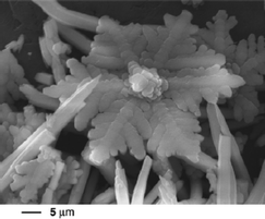 | ||
| Fig. 17 Strange floral shape of vaterite.90 | ||
Chang et al.45 implemented aragonite crystal growth investigations in the presence of MF with the use of a fluidized-bed crystallizer. The crystals were grown from a solution prepared by mixing calcium chloride and sodium carbonate in deionized water. During the experiments, an auto-titrator was utilized in keeping properties of the solution (such as pH, ion activity ratios, ionic concentration and relative super-saturation) constant. The MFs were produced by a commercial magnetic equipment (0.18 T) and a permanent magnet (0.02 T). The authors observed the absence of aragonite seed crystals when there was no MF application at room temperature; however, aragonite crystals crystallized when MF was applied with a faster rate of aragonite crystallization observed for the higher magnetic field strength. It was shown that under the conditions of MF application and low pH levels, aragonite crystals exhibited faster growth rates and calcite growth was stifled and even almost halted. Furthermore, aragonite growth was also boosted by high supersaturation and activity ratios way above 1.
Correspondingly, Tai et al.110 established that MF preempted calcite growth significantly under conditions of low pH levels and supersaturation. Conversely, high pH and relative supersaturation levels enhanced the growth rate of calcite MF treated samples.
In a different study, Tai et al.91 examined the impact of MF on the growth of aragonite crystals also using a fluidized bed crystallizer and different permanent magnets. When MF treatment was applied, the calcite growth rates (recorded using the method of constant composition) was observed to be a lot less than those in the untreated samples, with stronger MFs having a more pronounced effect.
Lipus and Dobersek111 investigated the effects of permanent magnets on scaling in tap water. It was discovered that scale was reduced during the magnetization runs, despite having aragonite precipitated in the presence and absence of MF. The aragonite formed instead of calcite, probably due to the presence of Mg2+ ions, which were abundant enough to inhibit the precipitation of calcite. The aragonite crystals were much less thinner when MF treatment was not carried out. A faster nucleation rate or suppressed growth of aragonite crystals, promoted by MF application, was posited.
There is overwhelming evidence that MF results in the favorable formation of aragonite, forming soft non-adherent scale. There are very few reports, however, that suggest otherwise.108 The modifications in the crystalline phase of CaCO3 to aragonite may be the key factor in the modus operandi of MF scale treatment.
8.13. Pipe material
From several studies, it appears that the type of material could have a part to play in the formation of scale.112–117 The potency of MF for scale reduction on different pipe materials was investigated by Gabrielli et al.118 They made use of pure water containing 200 mg L−1 Ca2+ prepared by dissolving 500 mg L−1 CaCO3 in deionized water followed by bubbling of CO2 (this ensured that the ions present in water were only Ca2+, CO32− and HCO3−). They also prepared salted water using the ASTM D1141 (ref. 119) procedure with the additional step of including sulfate ions and excluding magnesium ions. The pipe materials used were stainless steel, copper, and two types of PVC they labelled as PVC I and PVC II. PVC I was loaded with calcium carbonate and alumina. A magnetic field of 0.16 Tesla (T) was employed in the treatment process. The authors reported a reduction in the ionic calcium concentration of 18% for PVC II and a reduction in the ionic calcium concentration of 28% for stainless steel and copper after treatment with MF for about a minute. An efficiency improvement of 5% was noted after 30 minutes. The authors also noted that there was no noticeable effect of MF treatment on the ionic calcium concentration when PVC I was used as the pipe material. The scaling power of the treated water was measured by using a quartz crystal microbalance and they observed a higher scaling potential in the conducting materials (which are stainless steel and copper) after treatment with MF for about 12 seconds and also noted a significant scaling potential in PVC II when compared to PVC I. The authors pointed out that the calcium carbonate loaded in PVC II could have an effect on the nucleation rate of seeds.Alimi et al.85 also conducted MF treatment tests using pipes of various materials – Tygon, PVC, PTFE (polytetrafluoroethylene), copper and stainless steel. They treated a working solution magnetically in a closed loop for about 15 minutes and then went on to perform a precipitation test to determine the amount of CaCO3 formed by homogeneous nucleation and the total CaCO3 precipitated.
The CaCO3 formed by homogeneous nucleation was determined by separating the precipitate in the solution using filter membranes with a pore size of about 0.45 μm. The total precipitated calcium carbonate was evaluated by measuring the ionic concentration of calcium left in the solution. The conditions set by the authors are: flow rates – 0.54, 0.74, and 0.94 L min−1; pH – 6, 7, and 7.5; the tested solution comprised 0.4 g L−1 reagent grade CaCO3 dissolved in deionized water by bubbling pure CO2. They used permanent magnets to generate the MF. The authors observed an increase in total precipitated CaCO3 of 10 and 17% in PTFE and Tygon, respectively, which was more pronounced than for copper, stainless steel and PVC. They also observed the greatest homogeneous precipitation when PTFE pipes were used. Based on the authors' results, they deduce that non-conductive materials were the most efficient in this application, and that copper and stainless steel yielded less significant results (see Fig. 18).
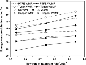 | ||
| Fig. 18 Variation of precipitation with a pipe material (hollow shapes represent MF treatment while filled shapes represent non-MF treatment).85 | ||
They however concluded that the observed pipe material effect could be due to contaminants dissolved in the water from the pipes, which act as seeds for CaCO3 precipitation in the bulk solution.
8.14. Dissolved gas concentration
Lee et al.40 observed that during the MF treatment of distilled-deionized water, a notable amount of outgassing occurred. They performed experiments using magnetically treated water (MTW), prepared using water partially outgassed by sonication, so as to ensure low gas levels while performing the MF treatment. They monitored readings for 24 hours during the MF treatment and reported a reduction in conductivity and surface tension, with an increase in IR absorption, which were more pronounced in the partially outgassed sample. A reversal in the conductivity trend was recorded for the non-outgassed water when juxtaposed with that of the outgassed sample as shown in Fig. 19.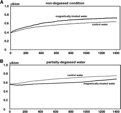 | ||
| Fig. 19 Effect of gas levels on variation of conductivity in the presence of MF.40 | ||
The authors infer that gas molecules possibly affect the degree to which MF treatment is effective to water. They recommend that since gas levels hinder the efficacy of MF treatment, then the measurements involving MF treatment should be taken at low gas levels.
Otsuka and Ozeki120 conducted a series of experiments to evaluate the effects of air/O2 on MF treatment. Ultrapure water (Milli-Q water, 18 MΩ) placed in a sealed flask and subjected to a reciprocating motion of about 30 times per minute at 298 K for 2.5 h was treated with a steady MF of about 6 T at the center. The same procedure was performed without MF concurrently. The effect of the MF treatment was evaluated by measuring the contact angle when the experiments were conducted in the absence of air even when electrolytes were added to the pure water (i.e. all procedures were performed in a vacuum), inferring that there are no MF effects in the absence of air.
Interestingly, a decrease/reduction in the contact angle was observed when the magnetic treatment was executed upon dissolving O2 in the pure water, indicating that magnetic effects could be enhanced by the presence of O2 and suggest that O2 may be a dominant factor for MF treatment. Based on their observation, the authors suggested that ionic species do not bring about any effects in the absence of air – an idea which contradicts the mechanism of Lorentz forces.
If indeed MF treatment is observed only in water containing O2, then the idea of Lorentz forces (which several researchers have labeled) serving as the explanation of MF treatment is questioned. One would expect MF effects to be observed irrespective of the gas content of a solution, since Lorentz forces should act directly on ionic species, but this is not so.
In another set of experiments much more related to scaling, the authors prepared CaCO3 by mixing Na2CO3 and CaCl2 at 298 K using MF treated water in the absence of air (vacuum) and in the presence of air or O2. They reported no effects on CaCO3 formation in a vacuum but observed that SEM images of CaCO3 were altered by MF (mainly noted aragonite formation) when the water is exposed to O2 or air. The aragonite phase of calcium carbonate forms soft scale that easily comes off a substrate during fluid flow. This reported formation of aragonite, only in the presence of O2, could suggest that MF effects are potent when there are gases present in a solution.
Conclusions
While there are inconsistencies in the results obtained by different researchers, a majority of the reports indicate the ability of MF to modify the precipitate deposited to either aragonite or vaterite, which form soft non-adherent scale. Still, the exact mechanism by which this action is observed is still open to contention. The most widely reported mechanisms have been attributed to Lorentz force, although there is strong evidence that suggests otherwise. Essentially, if Lorentz force is truly responsible for the observed effects, then there should be no MF effects under static conditions and, also, the effects should be observed even in solutions that contain ionic species without any gases present. These pieces of evidence tend to indicate that, at the very least, Lorentz force is not the only mechanism at play or, at the extreme, that it does not have any part to play in MF water treatment. This solicits the question, what is the modus operandi of MF water treatment? Given that the numerous studies pertaining to this topic have been performed under diverse conditions – temperature, flow rate, concentration, composition, magnetic field strength, etc. – it is therefore difficult to conclusively and irrevocably establish the potency of MF treatment.The acceptability of this method hinges upon consistent results and generally undisputable explanations for their effects. Well planned experiments need to be performed to establish the efficacy or inefficacy of this method. If indeed it has any usefulness, then the practical application has to be investigated in terms of its applicability on a large scale and under varying conditions. Most of the effects have been reported to be observed on the laboratory scale. The large scale implicates another operating level, and these so-called effects could be minimal at that level of operation. There have been, however, a few reports of the successful applications on the large scale; hence MF water treatment cannot be totally discredited. Nevertheless, it is not proven that MF is capable of completely replacing the chemical method of scale treatment. What is most probable, going by the available research studies, is a reduction of the amount of chemicals used in treating scale. There is still a long way to go in the mysterious world of MF anti-scaling. Indeed MF anti-scale treatment involves very complex mechanisms; hence strict control and monitoring of parameters should be ensured to obtain unambiguous and reproducible results. Obviously, more probing is required to obtain a unified verdict on this highly debated method of water treatment before it can become a mainstream application.
Acknowledgements
Adetunji Alabi gratefully acknowledges Prof. Simo O. Pehkonen (University of Eastern Finland), who inspired and promoted the commencement of this work during his previous appointment at the Masdar Institute of Science and Technology. Masdar Institute of Science and Technology supported this work with the SG2014-000006 grant.Notes and references
- J. S. Baker and S. J. Judd, Water Res., 1996, 30, 247–260 CrossRef CAS.
- M. Crabtree, D. Eslinger, P. Fletcher, M. Miller, A. Johnson and G. King, Oilfield Rev., 1999, 11, 30–45 CAS.
- J. D. Donaldson and S. Grimes, in New Scientist, 1988, vol. 117, pp. 43–46 Search PubMed.
- Y. Zhang, H. Shaw, R. Farquhar and R. Dawe, J. Pet. Sci. Eng., 2001, 29, 85–95 CrossRef CAS.
- A. Antony, J. H. Low, S. Gray, A. E. Childress, P. Le-Clech and G. Leslie, J. Membr. Sci., 2011, 383, 1–16 CrossRef CAS PubMed.
- US Pat., US 50774 A, 1865 Search PubMed.
- M. Darvill, Water Waste Treat., 1993, 40 Search PubMed.
- M. Brown, in BP Technology, 1998, vol. 30, pp. 30–32 Search PubMed.
- J. Glater, J. L. York and K. S. Campbell, Scale formation and prevention, In Principles of Desalination Part B, Academic Press, New York, 2nd edn, 1980 Search PubMed.
- O. V. Roussak and H. D. Gesser, Applied Chemistry: Textbook for Engineers and Technologists, Springer, New York, 2nd edn, 2013 Search PubMed.
- J. MacAdam and S. A. Parsons, Rev. Environ. Sci. Bio/Technol., 2004, 3, 159–169 CrossRef CAS.
- D. T. Beruto and M. Giordani, in Res. Chem. Kinet., ed. R. G. Compton and G. Hancock, Elsevier, Amsterdam, 1995, vol. 3, pp. 175–213 Search PubMed.
- J. W. Mullin, Crystallization, Butterworth-Heinemann, Oxford, 4th edn, 2001 Search PubMed.
- N. F. Gray, Drinking Water Quality: Problems and Solutions, Cambridge University Press, Cambridge, UK, 2nd edn, 2008 Search PubMed.
- J. A. Wojtowicz, Journal of the Swimming Pool and Spa Industry, 2001, 4, 54–59 Search PubMed.
- J. D. Rodriguez-Blanco, S. Shaw and L. G. Benning, Nanoscale, 2011, 3, 265–271 RSC.
- L. G. Anderson, in Encyclopedia of Marine Geosciences, Springer Netherlands, Dordrecht, 2014, DOI:10.1007/978-94-007-6644-0_46-1, pp. 1–4.
- P. Bots, L. G. Benning, J.-D. Rodriguez-Blanco, T. Roncal-Herrero and S. Shaw, Cryst. Growth Des., 2012, 12, 3806–3814 CAS.
- J. D. Rodriguez-Blanco, S. Shaw, P. Bots, T. Roncal-Herrero and L. G. Benning, J. Alloys Compd., 2012, 536, S477–S479 CrossRef CAS PubMed.
- I. L. Moudrakovski, in Annual reports on NMR spectroscopy, ed. A. W. Graham, Academic Press, Oxford, UK, 1st edn, 2013, vol. 79, pp. 129–240 Search PubMed.
- S. B. Mubenga, MSc Thesis, Rand Afrikaans University, 1997 Search PubMed.
- A. Sarkar and S. Mahapatra, Cryst. Growth Des., 2010, 10, 2129–2135 CAS.
- T. Threlfall, Org. Process Res. Dev., 2003, 7, 1017–1027 CrossRef CAS.
- A. E. Martel and M. Calvin, Chemistry of Metal Chelate Compounds, Prentice Hall, Inc., New York, USA, 1952 Search PubMed.
- H. David, S. Hilla and S. Alexander, Ind. Eng. Chem. Res., 2011, 50, 7601–7607 CrossRef.
- US Pat., US140196 A, 1873 Search PubMed.
- US Pat., US438579 A, 1890 Search PubMed.
- T. Vermeiren, Anti-Corros. Methods Mater., 1958, 5, 215–219 CrossRef.
- US Pat., US5037546 A, 1991 Search PubMed.
- J. F. Grutsch, USA/USSR Symposium of Physical Mechanical Treatment of Wastewaters, Cincinnati, 1977 Search PubMed.
- J. F. Grutsch and J. W. McClintock, Corrosion 84, 1984, vol. 330 Search PubMed.
- C. A. McMahon, BEng., University of Southern Queensland, 2009 Search PubMed.
- R. Eliassen, R. T. Skrinde and W. B. Davis, J. - Am. Water Works Assoc., 1958, 50, 1371–1385 Search PubMed.
- E. A. Duffy, PhD. Dissertation, Clemson University, 1977 Search PubMed.
- A. D. Kney and S. A. Parsons, Water Res., 2006, 40, 517–524 CrossRef CAS PubMed.
- O. Sohnel and J. Mullin, Chem. Ind., 1988, 11, 356–358 Search PubMed.
- S. A. Parsons, S. J. Judd, T. Stephenson, S. Udol and B. L. Wang, Process Saf. Environ. Prot., 1997, 75, 98–104 CrossRef CAS.
- J. E. Alleman, Quantitative Assessment Effectiveness of Permanent Magnetic Water Conditioning Devices, Purdue University, West Lafayette, Indiana, 1985 Search PubMed.
- K. Higashitani and J. Oshitani, J. Colloid Interface Sci., 1998, 204, 363–368 CrossRef CAS PubMed.
- S. H. Lee, S. I. Jeon, Y. S. Kim and S. K. Lee, J. Mol. Liq., 2013, 187, 230–237 CrossRef CAS PubMed.
- A. Szkatula, M. Balanda and M. Kopec, Eur. Phys. J.: Appl. Phys., 2002, 18, 41–49 CrossRef CAS.
- K. W. Busch and M. A. Busch, Desalination, 1997, 109, 131–148 CrossRef CAS.
- V. Kozic and L. Lipus, J. Chem. Inf. Comput. Sci., 2003, 43, 1815–1819 CrossRef CAS PubMed.
- L. C. Lipus, J. Krope and L. Crepinsek, J. Colloid Interface Sci., 2001, 236, 60–66 CrossRef CAS PubMed.
- M.-C. Chang and C. Y. Tai, Chem. Eng. J., 2010, 164, 1–9 CrossRef CAS PubMed.
- N. Saksono, S. B. Yuliusman, R. W. Soemantojo and A. Manaf, Makara, Teknologi, 2009, 13, 79–85 Search PubMed.
- M. Colic and D. Morse, J. Phys. Colloids Surf. A, 1999, 154, 167–174 CAS.
- S. Knez and C. Pohar, J. Colloid Interface Sci., 2005, 281, 377–388 CrossRef CAS PubMed.
- F. Gilart, D. Deas, D. Ferrer, P. López, G. Ribeaux and J. Castillo, Chem. Eng. Process., 2013, 70, 211–216 CrossRef CAS PubMed.
- L. C. Lipus, B. Ačko and A. Hamler, Chem. Eng. Process., 2011, 50, 952–958 CrossRef CAS PubMed.
- D. L. Watt, C. Rosenfelder and C. D. Sutton, J. Clin. Periodontol., 1993, 20, 314–317 CrossRef CAS PubMed.
- A. Goldsworthy, H. Whitney and E. Morris, Water Res., 1999, 33, 1618–1626 CrossRef CAS.
- K. X. Zhou, G. W. Lu, Q. C. Zhou, J. H. Song, S. T. Jiang and H. R. Xia, J. Appl. Phys., 2000, 88, 1802–1805 CrossRef CAS PubMed.
- L. C. Lipus, B. Ačko and B. Neral, J. Cleaner Prod., 2013, 52, 374–379 CrossRef CAS PubMed.
- J. M. D. Coey and G. Hinds, J. Alloys Compd., 2001, 326, 238–245 CrossRef CAS.
- V. Philippe, L. Jacques, M. Pascale, M. Marie-Odile and T. Yolène, J. Chem. Phys., 2005, 122, 114513–114518 CrossRef PubMed.
- Y. Fujimura and M. Iino, J. Appl. Phys., 2008, 103, 49031–49034 CrossRef PubMed.
- M. Iino and Y. Fujimura, Appl. Phys. Lett., 2009, 94, 19021–19023 CrossRef PubMed.
- H. Hosoda, H. Mori, N. Sogoshi, A. Nagasawa and S. Nakabayashi, J. Phys. Chem. A, 2004, 108, 1461–1464 CrossRef CAS.
- K.-T. Chang and C.-I. Weng, J. Appl. Phys., 2006, 100, 043917 CrossRef PubMed.
- R. Cai, H. Yang, J. He and W. Zhu, J. Mol. Struct., 2009, 938, 15–19 CrossRef CAS PubMed.
- M. C. Amiri and A. A. Dadkhah, Colloids Surf., A, 2006, 278, 252–255 CrossRef CAS PubMed.
- Y. I. Cho and S.-H. Lee, Int. Commun. Heat Mass Transfer, 2005, 32, 1–9 CrossRef CAS PubMed.
- S. H. Lee, PhD. Thesis, Drexel University, 2002 Search PubMed.
- Y. I. Cho, S. H. Lee and W. Kim, ASHRAE Trans., 2003, 109, 346–357 CAS.
- C. E. Gruber and D. D. Carda, WQA Research report, South Dakota School of Mines and Technology, Rapid City, South Dakota, 1981 Search PubMed.
- N. I. Gamayunov, Russ. J. Appl. Chem., 1983, 56, 975–982 Search PubMed.
- S. A. Parsons, B.-L. Wang, S. J. Judd and T. Stephenson, Water Res., 1997, 31, 339–342 CrossRef CAS.
- R. Gehr, Z. A. Zhai, J. A. Finch and S. R. Rao, Water Res., 1995, 29, 933–940 CrossRef CAS.
- A. E. Nielsen, Kinetics of Precipitation, Pergamon Press, New York, 1964 Search PubMed.
- K. Higashitani, H. Iseri, K. Okuhara, A. Kage and S. Hatade, J. Colloid Interface Sci., 1995, 172, 383–388 CrossRef CAS.
- K. Higashitani, K. Okuhara and S. Hatade, J. Colloid Interface Sci., 1992, 152, 125–131 CrossRef CAS.
- K. Higashitani, A. Kage, S. Katamura, K. Imai and S. Hatade, J. Colloid Interface Sci., 1993, 156, 90–95 CrossRef CAS.
- K. Higashitani, J. Oshitani and N. Ohmura, Colloids Surf., A, 1996, 109, 167–173 CrossRef CAS.
- K. Higashitani and J. Oshitani, Process Saf. Environ. Prot., 1997, 75, 115–119 CrossRef CAS.
- M. Ricci, P. Spijker, F. Stellacci, J.-F. Molinari and K. Voïtchovsky, Langmuir, 2013, 29, 2207–2216 CrossRef CAS PubMed.
- L. Holysz, A. Szczes and E. Chibowski, J. Colloid Interface Sci., 2007, 316, 996–1002 CrossRef CAS PubMed.
- A. Szcze, E. Chibowski, L. Holysz and P. Rafalski, Chem. Eng. Process., 2011, 50, 124–127 CrossRef PubMed.
- X. Pang and B. Deng, Sci. China, Ser. G: Phys., Mech. Astron., 2008, 51, 1621–1632 CrossRef CAS.
- S. I. Jeon, D.-R. Kim and S. K. Lee, J. Korean Chem. Soc., 2001, 45, 116–130 CAS.
- S. I. Jeon, D. R. Kim, S. H. Lee, D. S. Kim and S. K. Lee, J. Korean Chem. Soc., 2002, 46, 7–13 CrossRef CAS.
- L. Jiang, J. Zhang and D. Li, Desalin. Water Treat., 2015, 53, 1275–1285 CAS.
- S. N. Akopian and S. N. Airapetian, Biofizika, 2005, 50, 265–270 CAS.
- M. C. Amiri, Sep. Purif. Technol., 2006, 47, 126–134 CrossRef CAS PubMed.
- F. Alimi, M. M. Tlili, M. B. Amor, G. Maurin and C. Gabrielli, Chem. Eng. Process., 2009, 48, 1327–1332 CrossRef CAS PubMed.
- E. Tombacz, C. Ma, K. W. Busch and M. A. Busch, Colloid Polym. Sci., 1991, 269, 278–289 CAS.
- A. Fathi, T. Mohamed, G. Claude, G. Maurin and B. A. Mohamed, Water Res., 2006, 40, 1941–1950 CrossRef CAS PubMed.
- W. N. Al Nasser, A. Shaikh, C. Morriss, M. J. Hounslow and A. D. Salman, Chem. Eng. Sci., 2008, 63, 1381–1389 CrossRef CAS PubMed.
- T. Chen, A. Neville and M. Yuan, J. Pet. Sci. Eng., 2005, 46, 185–194 CrossRef CAS PubMed.
- A. Rizzuti and C. Leonelli, Powder Technol., 2008, 186, 255–262 CrossRef CAS PubMed.
- C. Y. Tai, C.-K. Wu and M.-C. Chang, Chem. Eng. Sci., 2008, 63, 5606–5612 CrossRef CAS PubMed.
- H. E. L. Madsen, J. Cryst. Growth, 1995, 152, 94–100 CrossRef.
- Y. Wang, J. Babchin, L. T. Chernyi, R. S. Chow and R. P. Sawatzky, Water Res., 1997, 31, 346–350 CrossRef CAS.
- J. D. Donaldson, presented in part at the UK CORROSION AND EUROCORR 94, Bournemouth International Centre, UK, 31 October - 3 November 1994, 1994 Search PubMed.
- F. T. Ellingsen and E. A. Vik, in Proc of 14th World Congress of the International Water Supply Association, September 1982, Zurich, 1982, pp. 12–25 Search PubMed.
- D. T. Beruto and M. Giordani, Res. Chem. Kinet., 1995, 3, 175 CAS.
- K. W. Busch, M. A. Busch, J. L. McAtee, R. E. Darling and D. H. Parker, Evaluation of the Principles of Magnetic Water Treatment, API Publ., 1985, 960 Search PubMed.
- F. T. Ellingsen and H. Kristiansen, Vatten, 1979, 35, 309–315 Search PubMed.
- D. M. Dawson, Corros. Prev. Control, 1990, 37, 61–64 CAS.
- R. F. Benson, B. B. Martin, D. F. Martin and R. K. Carpenter, J. Environ. Sci. Health, Part A: Environ. Sci. Eng. Toxic Hazard. Subst. Control, 1994, 29, 1553–1564 Search PubMed.
- K. Joshi and P. Kamat, J. Indian Chem. Soc, 1966, 43, 620–622 CAS.
- B. Gonet, Bioelectromagnetics, 1985, 6, 169–175 CrossRef CAS PubMed.
- A. Shahryari and M. Pakshir, J. Mater. Process. Technol., 2008, 203, 389–395 CrossRef CAS PubMed.
- E. Raisen, presented in part at the Corrosion 84, New Orleans, Louisiana, 1984 Search PubMed.
- E. Yee, J. Lee, D. Lim and B. Chun, in Adv. Mater. Res., Trans Tech Publications, Switzerland, 2012, vol. 594–597, pp. 2045–2055 Search PubMed.
- W. N. Al Nasser, A. H. Al Ruwaie, M. J. Hounslow and A. D. Salman, Powder Technol., 2011, 206, 201–207 CrossRef CAS PubMed.
- C. Gabrielli, G. Maurin, G. Poindessous and R. Rosset, J. Cryst. Growth, 1999, 200, 236–250 CrossRef CAS.
- M. Gryta, Sep. Purif. Technol., 2011, 80, 293–299 CrossRef CAS PubMed.
- L. N. Plumber and E. Busenberg, Geochim. Cosmochim. Acta, 1982, 46, 1011–1040 CrossRef.
- C. Y. Tai, M.-C. Chang, R.-J. Shieh and T. G. Chen, J. Cryst. Growth, 2008, 310, 3690–3697 CrossRef CAS PubMed.
- L. C. Lipus and D. Dobersek, Chem. Eng. Sci., 2007, 62, 2089–2095 CrossRef CAS PubMed.
- S. Keysar, R. Semiat, D. Hasson and J. Yahalom, J. Colloid Interface Sci., 1994, 162, 311–319 CrossRef CAS.
- Q. Yang, J. Ding and Z. Shen, Chem. Eng. Sci., 2000, 55, 797–805 CrossRef CAS.
- J. Macadam and S. Parsons, Water Sci. Technol., 2004, 49, 153–159 CAS.
- J. D. Doyle, K. Oldring, J. Churchley and S. A. Parsons, Water Res., 2002, 36, 3971–3978 CrossRef CAS.
- M. Förster, W. Augustin and M. Bohnet, Chem. Eng. Process., 1999, 38, 449–461 CrossRef.
- H. Müller-Steinhagen, Heat Exchanger Fouling: Mitigation and Cleaning Techniques, IChemE, Warwickshire, 2000 Search PubMed.
- C. Gabrielli, R. Jaouhari, G. Maurin and M. Keddam, Water Res., 2001, 35, 3249–3259 CrossRef CAS.
- D1141-98, ASTM International, West Conshohocken, Pennsylvania, 2008.
- I. Otsuka and S. Ozeki, J. Phys. Chem. B, 2006, 110, 1509–1512 CrossRef CAS PubMed.
| This journal is © The Royal Society of Chemistry 2015 |


