 Open Access Article
Molybdenum disulfide (MoS2) based photoredox catalysis in chemical transformations
Praveen P. Singh
 a,
Surabhi Sinha
a,
Geetika Pandey
b and
Vishal Srivastava
a,
Surabhi Sinha
a,
Geetika Pandey
b and
Vishal Srivastava
 *c
*c
aDepartment of Chemistry, United College of Engineering & Research, Prayagraj 211002, Uttar Pradesh, India. E-mail: ppsingh23@gmail.com
bDepartment of Physics, United University, Prayagraj 211012, Uttar Pradesh, India
cDepartment of Chemistry, CMP Degree College, University of Allahabad, Prayagraj-211002, Uttar Pradesh, India. E-mail: vishalgreenchem@gmail.com
First published on 18th October 2022
Abstract
Photoredox catalysis has been explored for chemical reactions by irradiation of photoactive catalysts with visible light, under mild and environmentally benign conditions. Furthermore, this methodology permits the activation of abundant chemicals into valuable products through novel mechanisms that are otherwise inaccessible. In this context, MoS2 has drawn attention due to its excellent solar spectral response and its notable electrical, optical, mechanical and magnetic properties. MoS2 has a number of characteristic properties like tunable band gap, enhanced absorption of visible light, a layered structure, efficient photon electron conversion, good photostability, non-toxic nature and quantum confinement effects that make it an ideal photocatalyst and co-catalyst for chemical transformations. Recently, MoS2 has gained synthetic utility in chemical transformations. In this review, we will discuss MoS2 properties, structure, synthesis techniques, and photochemistry along with modifications of MoS2 to enhance its photocatalytic activity with a focus on its applications and future challenges.
1 Introduction
Molybdenum disulfide (MoS2) is an inorganic compound of the transition metal dichalcogenide (TMD) series. It is one of the most used photocatalysts that has a wide range of applications in different fields. It is applicable to degrade pharmaceutically active compounds (PhACs), synthetic dyes (rhodamine B, methylene blue, methyl orange and novacron red Hunts-man), pesticides and herbicides. It also employed for photocatalytic evolution of oxygen, nitrogen fixation, ammonia synthesis and water electrolysis.1–7In recent years, MoS2 has received much attention due to its unique electrical and optical properties.8a MoS2 is a two-dimensional (2D) transition metal dichalcogenide, a narrow band semiconductor with a band gap of 1.9 eV which can be altered by adjusting the number of layers. Among all 2D TMDs, MoS2 is one of the few with a natural layered structure, indicating that MoS2 can be stripped to obtain high-quality 2D MoS2 without complicated chemical synthesis.8b Therefore, the cost of preparing 2D MoS2 is much lower than other 2D TMDs due to the simple synthesis conditions. More importantly, 2D MoS2 is a 2D semiconductor with a direct band-gap, which has the best electric performance among 2D TMDs.8c These make 2D MoS2 get more attention among 2D TMDs.
Several characteristics of MoS2 such as high absorbance in the visible region,9 high carrier mobility,10 stability,11 preferable catalytic activity,12 good photostability,13 outstanding electrochemical properties,14 strong surface adsorption capacity and higher specific surface area15 favours its application as a photocatalyst as well as a co-catalyst and also, it is capable of addressing the limitations faced by typical photocatalysts. Additionally, MoS2 is found to be abundant and cheap.7 Currently, semiconductor photocatalysts with controllable morphologies are gaining significant attraction in applications associated with environmental remediation process.16 Phase engineering, defect engineering, doping of external materials, interlayer engineering, surface modification, and heterojunction17a,b construction make MoS2 more flexible in terms of tuning its properties during synthesis.
Molybdenum disulfide (MoS2)17c has emerged as one of the most important two-dimensional functional materials, popular new co-catalysts due to their excellent photocatalytic activity, substantial adsorptivity, great value and its non-toxicity. The visible region of electromagnetic spectrum exhibits the absorption spectrum of 2D MoS2, providing a plethora of opportunities for widespread applications.17d Applications for MoS2-based materials are said to include energy storage,17e hydrogen production,17f pollutant degradation,17g disinfection,17h etc. Numerous studies have recently provided a summary of photocatalytic properties of MoS2 for numerous application areas.17i–n
In continuation of our work on photocatalysed organic synthesis18,19 this review aims to provide a comprehensive report on the current research, especially the role of MoS2 in the chemical transformation.
2 Synthesis of MoS2
For the most part, two different synthetic procedures are used to create MoS2: (1) a top-down strategy that involves exfoliating bulk MoS2 to create materials with one or two monolayers, and (2) a bottom-up strategy that uses techniques like hydrothermal or chemical vapour deposition. Several methods exist for the preparation of MoS2 using different molybdenum precursors and sulfur sources, like elemental sulfur powder,20 thiourea,21 thioacetamide,22 and L-cysteine.23 By regulating variables such the reaction solvent, temperature, pH, reaction time, and the application of surfactants or ligands, which are essential for managing the synthesis to create the desired chalcogenide, a variety of fascinating morphologies can be created. Table 1 exhibits the different methods that have been used to synthesize MoS2 materials alongside the applications of the synthesized materials. The most used methods are solid-state,24 hydrothermal,25,26 solvothermal,27 and hybrid methods.28,29| No. | Synthesis method | Metal precursor used | Source of sulfur used | Morphology and particle size | Applications | Ref. |
|---|---|---|---|---|---|---|
| 1 | Colloidal | Mo(CO)6 | Sulfur powder | Nanosheets | Electrochemical studies | 1 |
| 2 | Hydrothermal | (NH4)Mo7O24·4H2O | Thiourea (H2CSNH2) | Layered MoS2 nanoflowers with ∼0.1 μm particle size | Photocatalytic degradation of methylene blue and crystal violet dyes | 2 |
| 3 | Hydrothermal | Sodium molybdate dihydrate (Na2MoO4·2H2O) | Thioacetamide (C2H5NS) | Nano flowers with average size ∼100 nm | Photocatalytic degradation of rhodamine B | 3 |
| 4 | Hydrothermal | Sodium molybdate dihydrate (Na2MoO4·2H2O) | L-cysteine | Quantum dots with ∼2.5 nm particle size | Detection of methyl parathion (pesticide) | 4 |
| 5 | Hydrothermal | (NH4)MoS4 | (NH4)MoS4 | Fluorescent probe for hyaluronidase detection | 5 | |
| 6 | Chemical Exfoliation | Commercially available MoS2 powder | Nanosheets | Photocatalytic oxidation of benzyl halides | 6 | |
| 30 | ||||||
| 7 | Chemical vapor Deposition | Ammonium heptamolybdate | Sulfur | Not mentioned | 7 | |
| 31 | ||||||
| 8 | Colloidal | Ammonium tetrathiomolybdate [(NH4)2MoS4] | Ammonium tetrathiomolybdate [(NH4)2MoS4] | Spherical quantum dots with average size ∼5 nm | Bioimaging | 8 |
| 32 | ||||||
| 9 | Heating | Mo(acac)2 | 1-Dodecanethiol | Nanosheet | Electrical bistability performance | 9 |
| 33 | ||||||
| 10 | Hot injection | Molybdenum(V) chloride (MoCl5) | N,N′-diphenylthiourea | Nanosheets | 10 | |
| 34 | ||||||
| 11 | Hydrothermal | Sodium molybdate dihydrate (Na2MoO4·2H2O) | Thioacetamide (CH3CSNH2) | Coral-like | Lubrication additive; photocatalytic degradation of liquid paraffin | 11 |
| 35 | ||||||
| 12 | Hydrothermal | Na2MoO4·2H2O | Cysteine | Quantum dots with 2 ∼3.5 nm particle size | Fluorescent probe for sensing of hydroquinone and bioimaging | 12 |
| 36 | ||||||
| 13 | Solid state | (NH4)6Mo7O24·4H2O | Sulfur | Nanosheets, thinner than 5 nm | Photocatalytic degradation of rhodamine B | 24 |
| 14 | Hydrothermal | Na2MoO4·2H2O | Thiourea (H2CSNH2) | Irregular with average size in the range 12–25 nm | Electrochemical studies | 25 |
| 15 | Hydrothermal | Ammonium hepta molybdate tetrahydrate [(NH4)6Mo7O24·4H2O] | Ammonium polysulfide | Ammonium polysulfide as the sulfur source: Uniform MoS2 nanospheres with average size of ∼100 nm | Lubrication additive | 27 |
| 16 | Hydrothermal | MoO3 | Potassium thiocyanate | Flowerlike MoS2 spheres with average diameter of 1–2 nm | Photocatalytic degradation of methylene blue | 37 |
| 17 | Hydrothermal | Na2MoO4·2H2O | L-cysteine | Microspheres comprising crossed-linked nanorods ∼100 nm in length | Photocatalytic degradation of thiocarbamate herbicides | 38 |
| 18 | Hydrothermal | Ammonium tetrathiomolybdate [(NH4)2MoS4] | Thiourea (H2CSNH2) | Flowerlike microsphere | Photocatalytic degradation of rhodamine B and methylene blue | 39 |
| 19 | Hydrothermal | (NH4)6Mo7O24·4H2O | Thiourea | Nanosheets | Detection of dopamine | 40 |
| 20 | Hydrothermal | (NH4)6Mo7O24·4H2O | Na2S | Hierarchical porous with the thickness of ∼20–40 nm | Detection of phenol sulphite oxidase, nicotinamide adenine dinucleotide oxidase and superoxide dismutase mimicking activities | 41 |
| 21 | Microwave | Ammonium tetrathiomolybdate [(NH4)2MoS4] | Ammonium tetrathiomolybdate [(NH4)2MoS4] | Quantum dots with average diameter of ∼1.72 nm | Determination of terramycin | 42 |
| 22 | Solid state | (NH4)2MoS4 | Thiourea | Sheetlike structure and ultrathin layers | Electrochemical measurement | 43 |
The benefits and drawbacks of synthesis techniques44 such as thermal annealing, plasma-assisted synthesis, magnetron sputtering-based synthesis, atomic layer deposition (ALD), and wet chemical processes are summarised in Fig. 1.
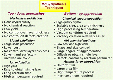 | ||
| Fig. 1 MoS2 synthesis techniques with their advantages and disadvantages.44 | ||
3 Properties of MoS2
MoS2 is a typical and stable 2D transition metal dichalcogenide which reveals that it is a semiconductor of MX2 type where the transition metals denote M and the chalcogen denotes X45 with three hexagonal planes (S–Mo–S), which is bonded to each other via ionic–covalent interactions.46 The sandwiched MoS2 is brought together to form sheets with an interlayer distance of 0.65 nm by the weak van der Waals force, which assumes responsibility for creating a 2D layered structure. Fig. 2a depicts the MoS2 structure as described. In addition, Fig. 2b reflects the fact that the presence of impurities in MoS2 alters its interlayer distance.47 As an n-type semiconductor, MoS2 has an indirect band gap of 1.2 eV in the bulk. The band gap of this semiconductor is inversely proportional to its number of layers. As a result, a direct band gap of 1.9 eV is obtained by almost reducing the number of layers to just one (Fig. 3c), making it a suitable photocatalyst in the visible region.11 The narrow band gap facilitates its high absorption of light in the visible region.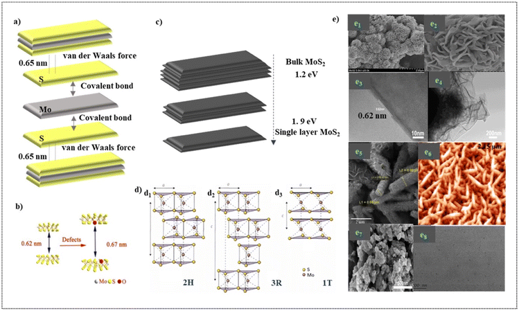 | ||
| Fig. 2 (a). Visualization of the layered structure of MoS2 and the forces responsible for its layered structure. (b). Pictorial illustration of the increased interlayer distance due to the presence of impurities. Adapted with permission from ref. 47, Copyrights 2022 Elsevier. (c). Graphical illustration of the tunable band gap exhibited by MoS2. (d). Crystal structures of MoS2. (d1). 2H, (d2). 3R and (d3).1T. Adapted with permission from ref. 11, Copyrights 2022 Elsevier. (e). Different morphologies portrayed by MoS2 (through synthesis) (e1). Nanoflowers at the resolution of 2 μm (e2). Nanoflowers at the resolution of 500 nm Adapted with permission from ref. 48, Copyrights 2022 Elsevier (e3). TEM image of the nanosheets at 10 nm (e4). TEM image of the nanosheets at 200 nm Adapted with permission from ref. 49, Copyrights 2022 Elsevier (e5). Nanotubes Adapted with permission from ref. 53, Copyrights 2022 Elsevier (e6). Nanoworms. Adapted with permission from ref. 54, Copyrights 2022 Elsevier (e7). Coral-like structure. Adapted with permission from ref. 49 Copyrights 2022 Elsevier (e8). Quantum dots. Reproduced from ref. 55 with permission from [Elsevier], Copyright [2022]. | ||
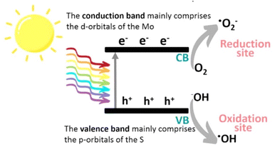 | ||
| Fig. 3 Schematic illustration of the photocatalytic mechanism of MoS2. Reproduced from ref. 29 with permission from [American Chemical Society], copyright [2022]. | ||
Crystal lattices of MoS2 exists in four polymorphic forms namely 1H, 2H, 1T and 3R (H- Hexagonal, T-Tetragonal and R-Rhombohedral) which are classified based on the stacking arrangement and the co- ordination between Mo and S atoms (Fig. 2d).11 MoS2 is synthesized in various morphologies (Fig. 2e) which includes nanoflowers (Fig. 2e1, Fig. 2e2),48 nanosheets (Fig. 2e3, Fig. 2e4),49 nanoflakes,50 nanocrystals, nanospheres,51 nanoribbons,52 nanotubes (Fig. 2e5),53 nanoworms (Fig. 2e6),54 coral-like structures (Fig. 2e7),49 nanodots and quantum dots (Fig. 2e8).55
Due to the 2D nature of MoS2, it's intrinsic properties are greatly influenced by the surrounding environment on the nanoscale. The suspended structures in these systems are hybrid systems with transport performance,56a–g tunable optoelectronic behaviour,56h–l and nanomechanical properties,56m–p all of which are fascinating on their own. The size, surface area, and surface energy of the MoS2 particles are determined by its morphology, which has a significant impact on how it executes in photocatalytic applications. Due to their large surface area and narrow band gap, MoS2 nanoflowers are more effective for absorbtion of visible light, which improves their photocatalytic efficacy. The shape of MoS2 nanoflowers determines their surface area, which in turn determines how well they operate as photocatalysts. MoS2 is anisotropic, piezocatalytic,56 hydrophobic and low-toxic, which has high specific surface area with high surface energy,57 high surface to volume ratio, high e− mobility, high optical absorption, high catalytic activity, good tribological properties,58 good thermal stability and free sulfur groups.59 Due to its low price and a wealth of earth reserves, it is commercially viable. As a result, MoS2's characteristics are largely in favour of its application as a photocatalyst.
Unfortunately, the catalytic activity of MoS2 is greatly inhibited due to its low dispersion ability which can be attributed to its hydrophobicity and low electrical conductivity.60 The formation of composites using MoS2 may be a viable and efficient way to get around this problem and maximise the benefits of MoS2 as a photocatalyst in aqueous bodies because the properties of other compounds in the composite may enhance the electrical conductivity and dispersion of MoS2 and thereby facilitate the exhibition of its full potential and surplus advantages.
4 Photochemistry of MoS2
MoS2 has attracted significant attention, and a wide range of desirable photocatalytic properties have been reported, such as narrow band gap energy, excellent optical absorptivity, and high mobility of charge carriers, in addition to low toxicity and cost. However, the performance of MoS2 is limited by photogenerated e−/h+ recombination, the edge activity effect, and photocorrosion. Past efforts to enhance the photocatalytic properties of MoS2 have involved controlling the morphology, modulation of energy bands through doping, band alignment through heterojunction formation, modification with carbon nanostructures, and combining with metal particles exhibiting surface plasmon resonance.The photocatalytic redox processes begin with the production of photoexcited charge carrier pairs (e−/h+). As illustrated in Fig. 3, upon irradiation the MoS2 simultaneously generates e− and h+, where the photogenerated e− is promoted to the CB, leaving behind the hole (h+) in the VB. Subsequently, these photogenerated carriers migrate to the surface of the MoS2 to participate in reduction (e−) and oxidation (h+) processes. Photoexcited e− may react with adsorbed O2 to produce ˙O2− radicals and, simultaneously, the h+ remaining in the VB can abstract an e− from hydroxyl ions or adsorbed H2O molecules to produce ˙OH radicals, which are powerful oxidizing agents that can react with harmful organic, inorganic, and biological compounds.
5 Modifications of MoS2 to improve its photocatalytic activity
The high e−/h+ pair recombination efficiency of MoS2 prevents it from being widely used in photocatalysis, despite the fact that it is a visible-light sensitive photocatalyst. This is a frequent problem with narrow band gap photocatalysts. Hence, to improve charge carrier separation, MoS2 has been doped and coupled with many varied materials such as metals,61 metal oxides,62 and carbon-based materials.63 Fig. 4 exhibits some of the modifications of MoS2. The doping of MoS2 with metal or non-metal dopants, as shown in Fig. 4a and b, can generate defects and change the optical band gap of MoS2. Charge separation can be enhanced when associated with metals due to the existence of the metal–MoS2 interface, as depicted in Fig. 4c. For instance, Cheah et al. reported an improved H2 evolution activity of Ag@MoS2 under irradiation by visible light.64 They reported that the deposition of Ag onto MoS2 assisted e− and h+ separation, prevented charge recombination, and hence, enhanced the overall photocatalytic performance. By creating a band offset and/or an electric field across the space-charge area at the junction between the two materials, a heterojunction enables the separation of e−/h+ pairs instantly. Fig. 4d shows the formation of two types of heterojunctions. A type I heterojunction results When the VB of MoS2 is greater than the VB of the second semiconductor and the conduction band (CB) of MoS2 is lower than the CB of the second semiconductor, allowing both electrons and holes to pass from the second semiconductor to the MoS2. In contrast, a type II heterojunction is created when the VB of MoS2 is above the VB of the second semiconductor, acting as a hole sink, while the CB of the second semiconductor is below the VB of MoS2, acting as an electron sink.65 For example, Hu et al. reported that an optimized Co-doped MoS2/g-C3N4 heterojuction exhibited the highest activity for the photocatalytic reduction of water, with a H2 evolution rate of 0.31 mmol g−1 h−1.66 According to these authors, Co-doped MoS2 has an edge-enriched 1T phase with more active sites than pristine MoS2, as well as a heterojunction with g-C3N4 to expedite charge transfer and separation and these factors contribute to the enhanced photocatalytic activity. Additionally, the creation of ternary and quaternary chalcogenides by including one or more additional elements into binary chalcogenides is a potential method for increasing the effectiveness of charge separation and interfacial charge transfer through the addition of additional surfaces. For example, Lim et al. fabricated a ZnMoS4/ZnO/CuS p-n heterojunction photo-catalyst that results in a hydrogen evolution rate 97% higher than an unoptimized ZnMoS4/CuS p-n structure.67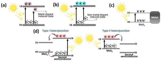 | ||
| Fig. 4 Modifications of MoS2 to improve its photocatalytic activity; (a) metal doping of MoS2, (b) nonmetal doping of MoS2, (c) metal deposited on MoS2, and (d) formation of a heterojunction with a second semiconductor. Reproduced from ref. 29 with permission from [American Chemical Society], copyright [2022]. | ||
A hydrothermal and calcination technique is used to successfully create a Z-scheme MoS2/CuO photocatalyst that degrades 2-mercaptobenzothiazole (MBT) with excellent activity (96 percent) when exposed to visible light68 (Fig. 5a–e).
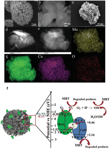 | ||
| Fig. 5 (a) SEM images of CuO, (b) MoS2, (c) MoS2/CuO, (d) TEM image of MoS2/CuO, (e) elemental mapping of MoS2/CuO, (f) photocatalytic degradation mechanism of MBT over the Z-scheme MoS2/CuO heterojunction under visible light irradiation. Reproduced from ref. 68 with permission from [Royal Society of Chemistry], copyright [2020]. | ||
MoS2 nanosheets and flower-shaped CuO combine to form a Z-scheme heterostructure, which significantly boosts the separation effectiveness of photogenerated carriers. CuO and MoS2's oxidation and reduction characteristics are enhanced by the Z-scheme electron transfer process that gives significant accumulation of photogenerated electrons and holes.
The authors proposed a possible Z-scheme charge transfer process and the reaction mechanism of MBT degradation by MoS2/CuO heterojunction under visible light irradiation and the results are shown in Fig. 5f. Electron–hole pairs are generated by the excitation of both MoS2 and CuO. The electrons on the CB of CuO migrate to the VB of MoS2 and combine with holes on the VB of MoS2. The photogenerated holes assembled by CuO can degrade MBT molecules in large quantities. In addition, due to the CB position of MoS2 is much more negative than the potential of O2/O2, the electrons on the CB of MoS2 will further undergo a reduction reaction to generate abundant O2, which will be further involved in the degradation process. Although CuO has a higher negative VB potential than OH, it is theoretically impossible to form OH; yet, some OH has been found using the ESR technique, which may be the result of further reducing O2. The Z-scheme charge transfer mechanism for MoS2/CuO significantly increases the separation efficiency of photogenerated carriers and positively influences the oxidizability and reducibility of the photocatalysts. Finally, the detailed photocatalytic reaction process of the Z-scheme MoS2/CuO heterojunction is in Fig. 5f.
A S-scheme MoS2/g-C3N4 photocatalyst is developed69 a one-pot solid-state reaction of thiourea and sodium molybdate as precursors at different temperatures under N2 gas was applied. The variation in component contents (MoS2 and gC3N4) is determined by the physicochemical characterization of the final products via an increase in synthesis temperature. The morphology and elemental composition of representatives were investigated using field emission scanning electron microscopy (FE-SEM), high resolution transmission electron microscopy (HR-TEM), along with energy dispersive X-ray spectroscopy (EDS) mapping (Fig. 6a–g).
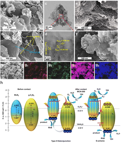 | ||
| Fig. 6 (a and b) FE-SEM; and (c and d) HR-TEM images of MCN-500; FE-SEM images of (e) MCN-600; and (f) CN-500; EDS mapping images of (g) mapping area, (g1) carbon, (g2) nitrogen, (g3) sulfur, and (g4) molybdenum, (h) schematic diagram of band alignment of heterojunction and S-scheme charge transfer on interface of MoS2 and g-C3N4. Reproduced from ref. 69 with permission from [Springer Nature], copyright [2021]. | ||
The degradation of Rhodamine B in an aqueous solution under visible light was used to evaluate the enhanced photocatalytic activity of the MoS2/gC3N4 composites. The best photocatalytic performance there was demonstrated by composites created at 500 °C, with a degradation efficiency of 90%, which was significantly better than that of a single g-C3N4. The improvement in light harvesting and the extension in the lifetime of photoinduced charge carriers of composites, which are the result of the synergistic interaction between the components, are credited with the significant improvement in photocatalytic performance. Besides, the photocatalytic mechanism is demonstrated to well-fit into the S-scheme pathway with apparent evidences (Fig. 6h).
6 Applications of MoS2 based nano-photocatalyst for chemical transformations
The MoS2 photocatalysis visible-light irradiation is considered a green alternative to traditional synthetic methodologies. As only mild conditions are needed and the formation of undesirable byproducts is decreased, it is a viable path for organic transformation processes. Summary of previous studies on photocatalytic organic transformation reactions using MoS2-based materials are tabulated in Table 2.| S. N. | Application | Photocatalyst used | Morphology | Particle size | Light source | Performance | Ref. |
|---|---|---|---|---|---|---|---|
| 1 | Photocatalytic oxidation of benzyl alcohol to benzaldehyde | Co-doped MoS2/g-C3N4 | 2D nanosheet morphology with curly stripes | 80 W LED lamp | Benzaldehyde production rate of 0.48 mmol g−1 h−1 | 66 | |
| 2 | Photocatalytic oxidative coupling of thiols | Pd@Cu/MoS2 | Spherical | 64.5 nm | 300 W Xe lamp | ∼99% conversion under 400–800 nm irradiation | 70 |
| 3 | Photocatalytic reduction of 4-nitrophenol | TiO2 hollow spheres/crumpled MoS2 nanosheet | Hollow sphere | ∼200 nm | 500 W Xe lamp | 99.35% photocatalytic reduction of 4-nitro- phenol | 71 |
| 4 | Photocatalytic conversion of CO2 to methane | MoS2/Cu | MoS2 nanosheets are coated on the surface of Cu nanorods | About 50–700 nm | 300 W Xe lamp | Maximum yield of methane ∼23 mmol g−1 h−1 | 72 |
| 5 | Photocatalytic reduction of CO2 to methanol | MoS2 grown on hexagonal boron nitride nanoplatelets | MoS2 nanosheets are uniformly grown over the hexagonal boron nitride nanoplatelets | Each MoS2 nanosheet is composed of 2–6 molecular lamellae | 20 W white LED lamp | Maximum yield of methanol 5994 μmol g−1 | 73 |
| 6 | Photocatalytic reduction of CO2 to methane and CO | In2S3/MoO3@MoS2 | Distorted hexagonal nanorods | 300 W Xe lamp | Yield ∼29.4 and ∼35.6 μmol g−1 h−1 for CH4 and CO, respectively | 74 | |
| 7 | Photocatalytic selective oxidation of benzyl alcohols to benzaldehyde | Ag3PO4 nanoparticle@MoS2 quantum dot/few-layered MoS2 nanosheet | Nanosheet | 300 W Xe lamp | ≤92% conversion of benzyl alcohol and ∼87% yield of benzaldehyde after 3 h of irradiation | 75 | |
| 8 | Photocatalytic reduction of 4- nitrophenol to 4-aminophenol | CdS-MoS2/rGO composite | Flowerlike morphology | 500 W Xe lamp | ≤70% reduction of 4-nitrophenol after 60 min of irradiation | 76 |
6.1 Cross-dehydrogenative coupling reaction
De et al. developed77a a methodology targeted for the utilization of sacrificial amine donors for C–H functionalization with MoS2 quantum dots (QDs) as the catalyst as well as the photosensitizer. Infact, QDs has emerged to be an active participant in the heterogeneous electron transfer process. This approach brings up new opportunities for photomediated organic transformations using nanomaterials without the need for external photosensitizers using a non-toxic, long-lasting procedure. The reduction cycle produces H2 from water, and the oxidative cycle culminates in the CDC product. (Fig. 7).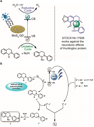 | ||
| Fig. 7 (a) Photomediated oxidation and reduction cycle of MoS2 QDs. (b) Proposed mechanism for the catalytic activity of MoS2 blue QDs in CDC reaction synchronized with HER. Reproduced from ref. 77a with permission from [American Chemical Society], copyright [2022]. | ||
The authors proposed a mechanistic pathway for the CDC reaction parallel to the photochemical HER mediated by MoS2 QDs (Fig. 7). An electron is excited from the valence band (VB) to the conduction band (CB) by radiation. In presence of O2, 2-Aryl-1,2,3,4-tetrahydroisoquinoline 1 is oxidized to radical cation 1+˙ via transferring an electron to the VB to regenerate the ground state of the QD. There is no need of any external photosensitizer for the oxidation of 1. The radical cation of 1 results the formation of iminium intermediate 1+ by losing a H˙. The nucleophile 2 attacks the iminium intermediate 1+ to give the targeted cross-coupled product 3 with simultaneous evolution of H2. Thus, QDs act as a photosensitizer as well as a catalyst that also transfer electron for the water-splitting process and further regenerated in the process. In the proposed mechanism, they have stated that the source of H can be from H2O as well as the nucleophile NuH. As their target was to design a methodology for the CDC reaction, they did not carry out any deuterated experiments to confirm the source of H2.
De et al. also demonstrated77b 1T (metallic)-2H (semiconducting) phase boundaries intrinsic to individual sheets of chemically exfoliated 2D-MoS2 that can serve as heterojunctions for enhanced photocatalysis compare to only semiconducting phase. Due to the abundance of heterojunctions in these multiphasic materials, chemically exfoliated 2D-MoS2 provides improved stability as well as transfer of photogenerated charges to the reactants, giving better yield. Significantly, they proved that this simple synthesize material works well as a photocatalyst for the aerobic oxidative coupling of amines to imines when subjected to visible light. Given its broad applications, they believe mixed phase 2D-MoS2 can be of interest to several industrial synthetic applications related to semiconductor-based photocatalysis. An additional benefit is that this heterogeneous photocatalyst can be regenerated up to five times without significant loss in the activity (Fig. 8).
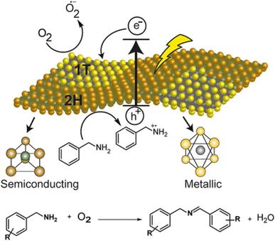 | ||
| Fig. 8 Plausible mechanism for the oxidative coupling of benzylamine to imine photocatalyzed by mixed-phase 2D-MoS2 nanosheets. Reproduced from ref. 77b with permission from [John Wiley & Sons, Inc.], copyright [2018]. | ||
Further De et al.77c have developed an efficient method for Cross Dehydrogenative Coupling (CDC) reaction by using mixed phase 2D-MoS2 nanosheets and Eosin Y alongside the photochemical Hydrogen Evolution Reaction (HER). The reaction has been carried out at room temperature under visible light irradiation and results in good to excellent yields. It is an example of a CDC reaction using mixed phase 2D-MoS2 nanosheets as a catalyst regenerator and Eosin Y as photosensitizer. Due to incomplete recovery of the catalyst, the material can be reused with slight loss in the yields. Additionally, the scope of this protocol can be used to create various C–C coupled products. This could be an illustration of how to completely utilise the oxidation and reduction cycles of several semiconductor-based photocatalysts. (Fig. 9).
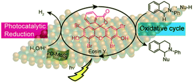 | ||
| Fig. 9 Schematic illustration of the 2D-MoS2 photocatalyzed oxidation and reduction cycles in presence of Eosin Y as photosensitizer. Reduction cycle produces H2 from water as reported earlier, whereas oxidative cycle is responsible for CDC Reaction and formation of additional H2. Reproduced from ref. 77c with permission from [Royal Society of Chemistry], copyright [2019]. | ||
6.2 Suzuki–Miyaura coupling reaction
Lim et al. demonstrated78 the incorporation of MoS2 nanosheets with Pd nanodots is a promising way for promoting the visible-light-induced Suzuki–Miyaura C–C coupling reaction. The MoS2 nanosheets decorated with Pd nanodots showed excellent photocatalytic activity. The turnover frequency for the biphenyl product was >1600 h−1 even under sunlight illumination at room temperature. Mechanistic researches revealed that the high catalytic activity of MoS2 originated from the efficient electron–hole pair generation mechanism under visible-light (Fig. 10).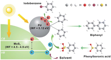 | ||
| Fig. 10 The Pd-nanodot decorated MoS2 micro/nanosheet for an efficient visible light induced photocatalytic Suzuki–Miyaura coupling reaction. Reproduced from ref. 78 with permission from [Royal Society of Chemistry], copyright [2017]. | ||
6.3 Photocatalytic NH3 synthesis
He et al. developed79 the efficient photoreduction of N2 to NH3 over ternary MoS2/C–ZnO composite, that was prepared via a combination of hydrothermal and photodeposition method (Fig. 11).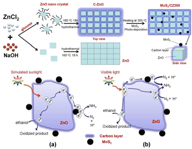 | ||
| Fig. 11 Preparation of MoS2/CZ300 photocatalyst and the suggested charge transfer mechanism of MoS2/CZ300 composite (a) under simulated sunlight (b) and visible light irradiation. Reproduced from ref. 79 with permission from [American Chemical Society], copyright [2018]. | ||
Several methods were employed to characterise the produced composite, and the results displayed that carbon was loaded onto the surface of ZnO instead of doped into the lattice in order to prevent charge carrier recombination. By thermal processing, the carbon content of C–ZnO can be altered by which enhances the effectiveness of charge separation. For calcination, the most favourable temperature of 300 °C determined. The separation of electron–hole pairs can be further improved by photodepositing MoS2 nanoparticles on the C–ZnO-300 sample, which traps electrons on the carbon layer. The ideal 1% MoS2/C-ZnO-300 composite exhibits the fastest NH3 generation rate under simulated sunlight irradiation at 245.7 μmol L−1 g−1 h−1, which is 9.3 and 4.0 times higher than that of ZnO and C–ZnO, respectively. However, when exposed to visible light, C–ZnO performs best, producing NH3 at a rate of 28.8 μmol L−1 g−1 h−1, indicating that the composite employs a different process. The carbon layer was thought to act as a photosensitizer by transferring electrons to ZnO or MoS2. The processes proposed have been confirmed by EIS and PC evaluations. The addition of a carbon layer and MoS2 nanoparticles to the ZnO increases the BET area. The increased surface area might be partially responsible for the higher photocatalytic performance. (Fig. 11a and b). There is another way to reduce N2 to NH3 via photocatalysis80,81.
6.4 Photoelectrochemical nitrogen reduction
The photoelectrochemical (PEC) technique, which uses both solar energy as well as electricity efficiently synthesize ammonia under ambient conditions. Han et al.82 have been synthesized MoS2@LZO heterostructures by assembling 2D-MoS2 nanoflakes on La2Zr2O7 nanofibers via a facile hydrothermal method (Fig. 12a).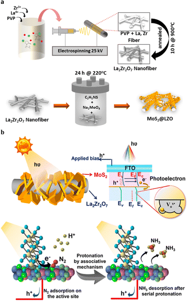 | ||
| Fig. 12 (a) Schematic illustration of the electrospun LZO nanofibers, followed by hydrothermal synthesis of MoS2@ LZO. (b) The band structure demonstrating the type II heterojunction for MoS2@LZO heterostructures with a reduced Fermi level under applied bias and solar illumination and schematic illustration of the PEC-NRR mechanism following the associative pathway for ammonia production. Reproduced from ref. 82 with permission from [American Chemical Society], copyright [2022]. | ||
Due to the electrical dispersion in LZO, the homogeneous assembly of MoS2@LZO prevents the photogenerated electron hole pair from recombining more quickly. Superior PEC-NRR performances can be seen as a result of the interaction between the localised electronic distribution in the MoS2@LZO heterostructures, oxygen vacancies in La2Zr2O7, excellent conductivity of the nanofibers, and increased exposure of surface sites for electron–hole generation in MoS2. The trapped photoelectron during N2 activation is donated by the reduction of N2 to NH3 at the oxygen vacancy, which serves as the active site for these reactions. The MoS2@LZO PEC catalyst exhibits a maximum ammonia yield rate of approximately 10.4 μg h−1 cm−2 and a higher faradaic efficiency of approximately 2.25% compared to pristine MoS2 and LZO. The heterostructure interface, which is rich in oxygen vacancies and offers a stable design with effective active sites, can be used to confirm this remarkable performance. Compared to the current MoS2 catalysts, MoS2@LZO demonstrates a higher ammonia yield, selective N2 adsorption, and excellent stability. The 2D-MoS2 nanoflakes, the La2Zr2O7 pyrochlore/fluorite structured nanofibers, and their heterostructure interfaces for enhanced ammonia production are presented with PEC-NRR mechanisms under ambient conditions. For various additional catalysis techniques to efficiently drive photoelectrocatalytic activity, the design strategy of inserting an n-type semiconductor over rich oxygen-vacant stable nanostructures to establish an interface can be used. (Fig. 12b).
6.5 Photocatalytic oxidation of nitrite
Zheng et al. reported83 the photocatalytic oxidation rate of NO2−under simulated solar irradiation, which can reach 62% by the MoS2/TiO2 composite synthesized in a hydrothermal system with a C2H5NS/Na2MoO4 molar ratio of 1![[thin space (1/6-em)]](https://www.rsc.org/images/entities/char_2009.gif) :
:![[thin space (1/6-em)]](https://www.rsc.org/images/entities/char_2009.gif) 0.6
0.6![[thin space (1/6-em)]](https://www.rsc.org/images/entities/char_2009.gif) :
:![[thin space (1/6-em)]](https://www.rsc.org/images/entities/char_2009.gif) under 200 oC for 24 h, which is significantly higher than that by pristine TiO2 NFs, P25 and pure MoS2. The photocatalytic oxidation process of NO2− follows the Langmuir–Hinshelwood kinetic model (pseudo-first order reaction), and the reaction rate constant (k) of the as-prepared composite is about 0.19194 h−1. MoS2 considerably increases the ability of catalyst ability to absorb visible light, which promotes the production of electrons and holes and ensures the strong photoactivity of catalyst. The composite has an about 2.2 eV band gap, which indicates improved visible light absorption. The titanium substrate is permanently attached to the composite using this straightforward, low-consumption approach, enabling recycling and ecologically responsible implementation possible (Fig. 13).
under 200 oC for 24 h, which is significantly higher than that by pristine TiO2 NFs, P25 and pure MoS2. The photocatalytic oxidation process of NO2− follows the Langmuir–Hinshelwood kinetic model (pseudo-first order reaction), and the reaction rate constant (k) of the as-prepared composite is about 0.19194 h−1. MoS2 considerably increases the ability of catalyst ability to absorb visible light, which promotes the production of electrons and holes and ensures the strong photoactivity of catalyst. The composite has an about 2.2 eV band gap, which indicates improved visible light absorption. The titanium substrate is permanently attached to the composite using this straightforward, low-consumption approach, enabling recycling and ecologically responsible implementation possible (Fig. 13).
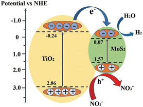 | ||
| Fig. 13 Schematic illustration of the energy band structure and electron–hole separation of MoS2/TiO2 composites. Reproduced from ref. 83 with permission from [Royal Society of Chemistry], copyright [2021]. | ||
6.6 Photocatalytic conversion of CO2 and H2O to CO, CH4 and H2 products
Ray et al. reported,84 theintegration of photoabsorber MoS2 and N-containing conducting polymer polypyrrole (PPy) over reduced graphene oxide improved CO2 photoreduction and H2 production (rGO). A variety of rGO-MoS/PPy nanocomposites were created and morphologically, structurally, and optically studied using various methods. Under pretend sunlight the optimal rGO-MoS /PPynanocomposite was found to exhibit a remarkable production of CO (3.9 μmol g−1 h−1), CH4 (1.50 μmol g−1 h−1), and H2 (4.19 μmol g−1 h−1) in the photocatalytic reduction of CO2 in an aqueous suspension (Fig. 14).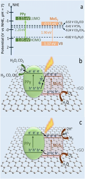 | ||
| Fig. 14 (a) Schematic representation of the band positions and potentials of PPy and MoS2. (b) Photocatalytic CO2 conversion into CH4 and CO gas via Z-scheme mechanism with rGO as redox mediator on the rGO-MoS2/PPy nanocomposite. (c) The conventional type II electron transfer for H2 production on the rGO-MoS2/PPy nanocomposite. Reproduced from ref. 84 with permission from [American Chemical Society], copyright [2020]. | ||
The synergistic effect of the MoS2, rGO, and PPy nanostructures, which encouraged the separation and migration of the photogenerated charges through the heterojunction interfaces and decreased electron–hole recombination, was attributed to the improvement in the photocatalytic performance of the highly active surface material rGO-MoS2/PPy-150. The PPy in the rGO-MoS2/PPy nanocomposite played multiple roles in improving the photocatalytic reduction of CO due to its superior conductivities, CO2 adsorption capabilities via its amine groups, and electron storage qualities. Better catalytic performance is possible due to the reduced PPy concentration in nanocomposite. Importantly, the strong recycling performance of rGO-MoS2/PPy-150 nanocomposite revealed the robustness and stability of photocatalyst (Fig. 14a–c).
7 Future outlook
Although many studies have focused on the synthesis of MoS2 and MoS2-based nanomaterials and their different uses, there are still a plethora of challenges:1. MoS2-based materials will be extensively used in a variety of disciplines and could one day become commercially feasible because of their unique physical and chemical qualities. With this, MoS2 will be applied to various media and released into the environment, potentially posing risks to both human health and the ecosystem. Therefore, a detailed evaluation of the toxicity of MoS2-based compounds is required.
2. The application of MoS2-based photocatalysts has so far been confined to laboratory-based research; it has not yet been investigated how well MoS2 performs in real-world environments, and a perfect photocatalyst that can be used on a wide scale and in industry has not yet been developed.
3. Certain MoS2 composites become unstable when exposed to visible light. Therefore, more investigation is required to design materials based on MoS2 that are photosensitive.
4. A significant challenge pertains for the development of practical techniques for the generation of MoS2 in quantities appropriate for industrial applications. For large-scale production, additional research into the scaling up of synthetic approaches is therefore needed.
8 Conclusion
In this review, we highlighted the different MoS2 structures, their synthesising techniques and properties. The primary benefits and drawbacks of synthesis approaches were also summarised. MoS2 is a promising material with a wide range of applications. MoS2 and MoS2-based nanomaterials are currently the topic of extensive research as promising photocatalyst for the photocatalytic degradation and inorganic and organic chemical transformation. MoS2 and MoS2-based materials have exceptional physicochemical features, due to which they exhibit wide range of synthetic applications like coupling reaction, oxidation, reduction as well as organic and inorganic compound production. This review relies on recent developments regarding the application of MoS2 in chemical transformations. The prospects for successful visible-light-induced photocatalysis using MoS2 based materials are finally discussed.Conflicts of interest
There are no conflicts to declare.References
- A. Majumder, D. Saidulu, A. K. Gupta and P. S. Ghosal, J. Environ. Manage., 2011, 293, 112858 CrossRef PubMed.
- A. L. Camargo-Perea, E. A. Serna-Galvis, J. Lee and R. A. Torres-Palma, Ultrason. Sonochem., 2021, 73, 105500 CrossRef CAS PubMed.
- Y. Rao, D. Xue, H. Pan, J. Feng and Y. Li, Chem. Eng. J., 2016, 283, 65–75 CrossRef CAS.
- M. H. F. Graumans, W. F. L. M. Hoeben, M. F. P. van Dael, R. B. M. Anzion, F. G. M. Russel and P. T. J. Scheepers, Environ. Res., 2021, 195, 110884 CrossRef CAS PubMed.
- P. Sharma, D. Kumar and S. Mutnuri, J. Pharm. Anal., 2021, 11, 320–329 CrossRef PubMed.
- Q. Zhou, Y. Huang, Y. Zhang, C. Xu, W. Huang, K. Yang, X. Chen and Y. Zhang, Mater. Chem. Phys., 2020, 276, 125333 CrossRef.
- Md. Ahmaruzzaman and V. Gadore, J. Environ. Chem. Eng., 2021, 9, 105836 CrossRef CAS.
- (a) X. Li, R. Shen, S. Mab, X. Chen and J. Xie, Appl. Surf. Sci., 2018, 430, 53–107 CrossRef CAS; (b) E. Canadell, A. L. Beuze, M. A. E. Khalifa, R. Chevrel and M. H. Whangbo, J. Am. Chem. Soc., 1989, 111, 3778–3782 CrossRef CAS; (c) J. N. Coleman, M. Lotya, A. O’Neil', S. D. Bergin, P. J. King, U. Khan, K. Young, A. Gaucher, S. De and R. J. Smith, Science, 2011, 331, 568–571 CrossRef CAS PubMed.
- F. Guo, X. Huang, Z. Chen, H. Ren, M. Li and L. Chen, J. Hazard. Mater., 2020, 390, 12215 Search PubMed.
- R. N. Dalila, M. K. Md Arshad, S. C. B. Gopinath, W. M. W. Norhaimi and M. F. M. Fathil, Biosens. Bioelectron., 2019, 132, 248–264 CrossRef CAS PubMed.
- Y. Yuan, R. T. Guo, L. F. Hong, X. Y. Ji, Z. S. Li, Z. D. Lin and W. G. Pan, Colloids Surf. A Physicochem. Eng. Asp., 2021, 611, 125836 CrossRef CAS.
- S. Ni, L. Yang, H. Qu, X. Zhu, Z. Xu, M. Yuan, H. Xing, L. Wang, J. Yu and H. Liu, J. Environ. Chem. Eng., 2021, 9, 105101 CrossRef CAS.
- L. Cheng, W. Huang, Q. Gong, C. Liu, Z. Liu, Y. Li and H. Dai, Angew. Chem., Int. Ed., 2014, 53, 7860–7863 CrossRef CAS PubMed.
- S. Yin, Y. Ding, C. Luo, Q. Hu, Y. Chen, J. Di, B. Wang, J. Xia and H. Li, Colloids Surf. A, 2021, 609, 125655 CrossRef CAS.
- L. Liu, J. Cao, M. Ali, J. Zhang and Z. Wang, Environ. Adv., 2021, 4, 100059 CrossRef CAS.
- M. Arumugam, Y. Yu, H. J. Jung, S. Yeon, H. Lee, J. Theerthagiri, S. J. Lee and M. Y. Choi, Environ. Res., 2021, 197, 111080 CrossRef CAS PubMed.
- (a) H. Wang, C. Li, P. Fang, Z. Zhang and J. Z. Zhang, Chem. Soc. Rev., 2018, 47, 6101–6127 RSC; (b) P. R. Sivaranjani, B. Janani, A. M. Thomas, L. L. Raju and S. S. Khan, J. Cleaner Prod., 2022, 352, 131506 CrossRef CAS; (c) M. H. Wu, L. Li, N. Liu, D. J. Wang, Y. C. Xue and L. Tang, Process Saf. Environ. Prot., 2018, 118, 40–58 CrossRef CAS; (d) K. F. Mak, C. Lee, J. Hone, J. Shan and T. F. Heinz, Phys. Rev. Lett., 2010, 105, 136805 CrossRef PubMed; (e) Y. Yuan, R.-t. Guo, L.-f. Hong, X.-y. Ji, Z.-s. Li, Z.-d. Lin and W.-g. Pan, Colloids Surf., A, 2021, 611, 125836 CrossRef CAS; (f) B. Han and Y. H. Hu, Energy Sci. Eng., 2016, 4, 285e304 Search PubMed; (g) M.-h. Wu, L. Li, N. Liu, D.-j. Wang, Y.-c. Xue and L. Tang, Process Saf. Environ. Prot., 2018, 118, 40e58 Search PubMed; (h) X. Meng, Z. Li, H. Zeng, J. Chen and Z. Zhang, Appl. Catal. B: Environ., 2017, 210, 160e172 CrossRef; (i) G. Zhang, H. Liu, J. Qu and J. Li, Energy Environ. Sci., 2016, 9, 1190e1209 Search PubMed; (j) J. Theerthagiri, R. A. Senthil, B. Senthilkumar, A. Reddy Polu, J. Madhavan and M. Ashokkumar, J. Solid State Chem., 2017, 252, 43e71 CrossRef; (k) Z. Li, X. Meng and Z. Zhang, J. Photochem. Photobiol. C, 2018, 35, 39e55 CrossRef; (l) Z. Liang, R. Shen, Y. H. Ng, P. Zhang, Q. Xiang and X. Li, J. Mater. Sci. Technol., 2020, 56, 89e121 CrossRef; (m) D. B. Sulas-Kern, E. M. Miller and J. L. Blackburn, Energy Environ. Sci., 2020, 13, 2684e2740 RSC; (n) N. Thomas, S. Mathew, K. M. Nair, K. O'Dowd, P. Forouzandeh, A. Goswami, G. McGranaghan and S. C. Pillai, Mater. Today Sustain., 2021, 13, 100073 CrossRef.
- (a) V. Srivastava, P. K. Singh and P. P. Singh, Croat. Chem. Acta, 2015, 88(1), 59–65 CrossRef CAS; (b) V. Srivastava, P. K. Singh and P. P. Singh, Croat. Chem. Acta, 2015, 88(3), 227–233 CrossRef CAS; (c) V. Srivastava, P. K. Singh and P. P. Singh, Asian J. Chem., 2016, 28(10), 2159–2163 CrossRef CAS; (d) V. Srivastava, P. K. Singh and P. P. Singh, Croat. Chem. Acta, 2017, 90(3), 435–441 CrossRef CAS; (e) V. Srivastava, P. K. Singh, S. Kanaujia and P. P. Singh, New J. Chem., 2018, 42, 688 RSC; (f) P. K. Singh, P. P. Singh and V. Srivastava, Croat. Chem. Acta, 2018, 91(3), 383–387 CrossRef; (g) V. Srivastava, P. K. Singh and P. P. Singh, Tetrahedron Lett., 2019, 60, 40–43 CrossRef CAS; (h) V. Srivastava, P. K. Singh and P. P. Singh, Tetrahedron Lett., 2019, 60, 1333–1336 CrossRef CAS; (i) V. Srivastava, P. K. Singh and P. P. Singh, Tetrahedron Lett., 2019, 60, 151041 CrossRef CAS; (j) V. Srivastava, P. K. Singh and P. P. Singh, Rev. Roum. Chim., 2020, 65(3), 221–226 CrossRef.
- (a) V. Srivastava and P. P. Singh, RSC Adv., 2017, 7, 31377–31392 RSC; (b) V. Srivastava, P. K. Singh, A. Srivastava and P. P. Singh, RSC Adv., 2020, 10, 20046 RSC; (c) A. Srivastava, P. K. Singh, A. Ali, P. P. Singh and V. Srivastava, RSC Adv., 2020, 10, 39495 RSC; (d) V. Srivastava, P. K. Singh, A. Srivastava and P. P. Singh, RSC Adv., 2021, 11, 14251–14259 RSC; (e) V. Srivastava and P. P. Singh, Org. Biomol. Chem., 2021, 19, 313–321 RSC; (f) P. P. Singh, P. K. Singh, M. Z. Beg, A. Kashyap and V. Srivastava, Synth. Commun., 2021, 51(20), 3033–3058 CrossRef CAS; (g) V. Srivastava, P. K. Singh, A. Srivastava, S. Sinha and P. P. Singh, Photochem, 2021, 1, 237–246 CrossRef; (h) V. Srivastava, P. K. Singh, S. Tivari and P. P. Singh, Org. Chem. Front., 2022, 9, 1485 RSC; (i) V. Srivastava, P. K. Singh and P. P. Singh, J. Photochem. Photobiol., C, 2022, 50, 100488 CrossRef CAS; (j) V. Srivastava and P. P. Singh, RSC Adv., 2022, 12, 18245 RSC.
- M. Alam Khan and Y. M. Kang, Synthesis and Electrochemical Performance of Colloidal MoS2 Nanosheets as an Anode Material in Sodium Ion Battery, J. Energy Storage, 2016, 252–257 CrossRef.
- H. K. Sadhanala, S. Senapati, K. V. Harika, K. K. Nanda and A. Gedanken, New J. Chem., 2018, 42(17), 14318–14324 RSC.
- J. S. Roy, G. Dugas, S. Morency and Y. Messaddeq, Phys. Rev. E, 2020, 120, 114114 CAS.
- N. Fahimi-Kashani, A. Rashti, M. R. Hormozi-Nezhad and V. Mahdavi, Anal. Methods, 2017, 9(4), 716–723 RSC.
- W. Chen, M. Liu, S. Wei, X. Li, L. Mao and W. Shangguan, J. Alloys Compd., 2020, 836, 155401 CrossRef CAS.
- C. Nagaraju, C. V. V. Muralee Gopi, J. W. Ahn and H. J. Kim, New J. Chem., 2018, 42(15), 12357–12360 RSC.
- W. Gu, Y. Yan, C. Zhang, C. Ding and Y. Xian, ACS Appl. Mater. Interfaces, 2016, 8(18), 11272–11279 CrossRef CAS PubMed.
- S. V. Prabhakar Vattikuti, C. Byon, C. Venkata Reddy, B. Venkatesh and J. Shim, J. Mater. Sci., 2015, 50(14), 5024–5038 CrossRef CAS.
- W. Chen, L. Sun, Q. Li, L. Huo and H. Zhao, Int. J. Hydrogen Energy, 2020, 45(43), 22459–22468 CrossRef CAS.
- A. Rahman, J. R. Jennings, A. L. Tan and M. M. Khan, ACS Omega, 2022, 7(26), 22089–22110 CrossRef CAS PubMed.
- N. Tian, Z. Li, D. Xu, Y. Li, W. Peng, G. Zhang, F. Zhang and X. Fan, Ind. Eng. Chem. Res., 2016, 55(32), 8726–8732 CrossRef CAS.
- J. H. Kim, J. Lee, S. Park, C. Seo, S. J. Yun, G. H. Han, J. Kim, Y. H. Lee and H. S. Lee, Curr. Appl. Phys., 2022, 33, 59–65 CrossRef.
- H. Lin, C. Wang, J. Wu, Z. Xu, Y. Huang and C. Zhang, New J. Chem., 2015, 39(11), 8492–8497 RSC.
- X. Li, A. Tang, J. Li, L. Guan, G. Dong and F. Teng, Nanoscale Res. Lett., 2016, 11(1), 171 CrossRef PubMed.
- (a) Y. Liu, Q. Zhong, K. Chen, J. Zhou, X. Yang and W. Chen, J. Mater. Sci.: Mater. Electron., 2017, 28(18), 13633–13637 CrossRef CAS; (b) L. Liu, Z. Huang, Y. Peng and P. Huang, New J. Chem., 2017, 41(15), 7674–7680 RSC.
- L. Liu, Z. Huang, Y. Peng and P. Huang, New J. Chem., 2017, 41(15), 7674–7680 RSC.
- L. Li, Z. Guo, S. Wang, D. Li, X. Hou, F. Wang, Y. Yang and X. Yang, Anal. Methods, 2019, 11(26), 3307–3313 RSC.
- B. Sheng, J. Liu, Z. Li, M. Wang, K. Zhu, J. Qiu and J. Wang, Mater. Lett., 2015, 144, 153–156 CrossRef CAS.
- S. Huang, C. Chen, H. Tsai, J. Shaya and C. Lu, Sep. Purif. Technol., 2018, 197, 147–155 CrossRef CAS.
- X. Zhang, H. Suo, R. Zhang, S. Niu, X. qi Zhao, J. Zheng and C. Guo, Mater. Res. Bull., 2018, 100, 249–253 CrossRef CAS.
- M. Sabar, U. Amara, S. Riaz, A. Hayat, M. Nasir and M. H. Nawaz, Mater. Lett., 2022, 308, 131233 CrossRef CAS.
- Y. Cai, L. Niu, X. Liu, Y. Zhang, Z. Zheng, L. Zeng and A. Liu, J. Hazard. Mater., 2022, 425, 128053 CrossRef CAS PubMed.
- X. Yu, Y. Meng, Y. Yan, X. Jin, G. Ni and J. Peng, Microchem. J., 2020, 152, 104406 CrossRef CAS.
- U. Chothe, C. Ugale, M. Kulkarni and B. Kale, Crystals, 2021, 11(6), 660 CrossRef CAS.
- S. Singh, A. Modak, K. Ki. Pant, A. Sinhamahapatra and P. Biswas, ACS Appl. Nano Mater., 2021, 4(9), 8644–8667 CrossRef CAS.
- V. Singh and S. Rath, Syst. Nanostruct., 2021, 128, 114617 CAS.
- V. Hasija, P. Raizada, V. K. Thakur, A. A. P. Khan, A. M. Asiri and P. Singh, J. Environ. Chem. Eng., 2020, 8, 104307 CrossRef CAS.
- M. Guo, Z. Xing, T. Zhao, Y. Qiu, B. Tao, Z. Li and W. Zhou, Appl. Catal. B Environ., 2020, 272, 118978 CrossRef CAS.
- K. Talukdar, K. Saravanakumar, Y. Kim, A. Fayyaz, G. Kim, Y. Yoon and C. M. Park, Composites Part B, 2021, 215, 108780 CrossRef CAS.
- L. Luo, M. Shi, S. Zhao, W. Tan, X. Lin, H. Wang and F. Jiang, J. Saudi Chem. Soc., 2021, 23, 762–773 CrossRef.
- X. Bai, H. Lv, Z. Liu, J. Chen, J. Wang, B. Sun, Y. Zhang, R. Wang and K. Shi, J. Hazard. Mater., 2021, 416, 125830 CrossRef CAS PubMed.
- J. Singh, S. R. Kumar and R. K. Soni, J. Alloys Compd., 2020, 849, 156502 CrossRef CAS.
- H. Jing, Chem. Phys., 2021, 548, 111241 CrossRef CAS.
- M. Nazifi, A. M. Ramezani, G. Absalan and R. Ahmadi, Sens. Actuators, B, 2021, 332, 129459 CrossRef CAS.
- A. Neetika Kumar, R. Chandra and V. K. Malik, Thin Solid Films, 2021, 725, 138625 CrossRef.
- Y. Jiao, Q. Huang, J. Wang, Z. He and Z. Li, Appl. Catal., B, 2019, 247, 124–132 CrossRef CAS.
- (a) A. Cepellotti, G. Fugallo, L. Paulatto, M. Lazzeri, F. Mauri and N. Marzari, Nat. Commun., 2015, 6, 6400 CrossRef CAS PubMed; (b) G. Fugallo, A. Cepellotti, L. Paulatto, M. Lazzeri, N. Marzari and F. Mauri, Nano Lett., 2014, 14, 6109–6114 CrossRef CAS PubMed; (c) X. Xu, L. F. C. Pereira, Y. Wang, J. Wu, K. Zhang, X. Zhao, S. Bae, C. T. Bui, R. Xie, J. T. L. Thong, B. H. Hong, K. P. Loh, D. Donadio, B. Li and B. Ozyilmaz, Nat. Commun., 2014, 5, 3689 CrossRef CAS PubMed; (d) S. Ghosh, W. Bao, D. L. Nika, S. Subrina, E. P. Pokatilov, C. N. Lau and A. A. Balandin, Nat. Mater., 2010, 9, 555–558 CrossRef CAS PubMed; (e) A. A. Balandin, S. Ghosh, W. Bao, I. Calizo, D. Teweldebrhan, F. Miao and C. N. Lau, Nano Lett., 2008, 8, 902–907 CrossRef CAS PubMed; (f) A. A. Balandin, MRS Bull., 2014, 39, 817–823 CrossRef CAS; (g) A. Branny, S. Kumar, R. Proux and B. D. Gerardot, Nat. Commun., 2017, 8, 15053 CrossRef CAS PubMed; (h) C. Palacios-Berraquero, D. M. Kara, A. R. P. Montblanch, M. Barbone, P. Latawiec, D. Yoon, A. K. Ott, M. Loncar, A. C. Ferrari and M. Atatüre, Nat. Commun., 2017, 8, 15093 CrossRef CAS PubMed; (i) S. Kumar, A. Kaczmarczyk and B. D. Gerardot, Nano Lett., 2015, 15, 7567–7573 CrossRef CAS PubMed; (j) J. Kern, I. Niehues, P. Tonndorf, R. Schmidt, D. Wigger, R. Schneider, T. Stiehm, S. Michaelis de Vasconcellos, D. E. Reiter, T. Kuhn and R. Bratschitsch, Adv. Mater., 2016, 28, 7101–7105 CrossRef CAS PubMed; (k) G. D. Shepard, O. A. Ajayi, X. Li, X. Y. Zhu, J. Hone and S. Strauf, 2D Mater., 2017, 4, 21019 CrossRef; (l) N. Morell, A. Reserbat-Plantey, I. Tsioutsios, K. G. Schädler, F. Dubin, F. H. L. Koppens and A. Bachtold, Nano Lett., 2016, 16, 5102–5108 CrossRef CAS PubMed; (m) C. H. Liu, I. S. Kim and L. J. Lauhon, Nano Lett., 2015, 15, 6727–6731 CrossRef CAS PubMed; (n) J. Lee, Z. Wang, K. He, J. Shan and P. X. L. Feng, ACS Nano, 2013, 7, 6086–6091 CrossRef CAS PubMed; (o) J. Chaste, A. Missaoui, S. Huang, H. Henck, Z. B. Aziza, L. Ferlazzo, A. Balan, A. T. C. Johnson, R. Braive and A. Ouerghi, ACS Nano, 2018, 12, 3235–3242 CrossRef CAS PubMed; (p) B. Bagchi, N. A. Hoque, N. Janowicz, S. Das and M. K. Tiwari, Nano Energy, 2020, 78, 1053 CrossRef PubMed.
- X. Hou, H. Jiang, M. K. A. Ali, H. Liu, D. Su and Z. Tian, J. Mol. Liq., 2020, 311, 113303 CrossRef CAS.
- Z. Bojarska, J. Kopytowski, M. Mazurkiewicz-Pawlicka, P. Bazarnik, S. Gierlotka, A. Rozen and L. Makowski, Tribol. Int., 2021, 160, 106999 CrossRef CAS.
- S. Kaushik, U. K. Tiwari, S. S. Pal and R. K. Sinha, Biosens. Bioelectron., 2019, 126, 501–509 CrossRef CAS PubMed.
- K. Peng, J. Wang, H. Wang, X. Li, P. Wan, H. Zhang and L. Bai, Appl. Clay Sci., 2019, 183, 105346 CrossRef CAS.
- M. Ikram, M. I. Khan, A. Raza, M. Imran, A. Ul-Hamid and S. Ali, Phys. Rev. E, 2020, 124, 114246 CAS.
- Ritika, M. Kaur, A. Umar, S. Mehta, S. Singh, S. Kansal, H. Fouad and O. Alothman, Materials, 2018, 11(11), 2254 CrossRef PubMed.
- M. Wang, P. Ju, J. Li, Y. Zhao, X. Han and Z. Hao, ACS Sustainable Chem. Eng., 2017, 5(9), 7878–7886 CrossRef CAS.
- A. J. Cheah, W. S. Chiu, P. S. Khiew, H. Nakajima, T. Saisopa, P. Songsiriritthigul, S. Radiman and M. A. A. Hamid, Catal. Sci. Technol., 2015, 5(8), 4133–4143 RSC.
- S. San Martín, M. J. Rivero and I. Ortiz, Catalysts, 2020, 10(8), 901 CrossRef.
- Y. Hu, X. Yu, Q. Liu, L. Wang and H. Tang, Carbon, 2022, 188, 70–80 CrossRef CAS.
- W. Y. Lim, H. Wu, Y. F. Lim and G. W. Ho, J. Mater. Chem. A, 2018, 6(24), 11416–11423 RSC.
- Y. Wang, X. Tang, Z. Liu, Y. Yan, B. Yang and Z. Zhu, New J. Chem., 2020, 44, 18264–18273 RSC.
- H. Tran Huu, M. D. N. Thi and V. P. Nguyen, et al., Sci. Rep., 2021, 11, 14787 CrossRef CAS PubMed.
- M. Yusuf, S. Song, S. Park and K. H. Park, Appl. Catal. A, 2021, 613, 118025 CrossRef CAS.
- N. Guo, Y. Zeng, H. Li, X. Xu and H. Yu, Mater. Lett., 2017, 209, 417–420 CrossRef CAS.
- T. Ilyas, F. Raziq, S. Ali, A. Zada, N. Ilyas, R. Shaha, Y. Wang and L. Qiao, Mater. Des., 2021, 204, 109674 CrossRef CAS.
- S. Kumari, R. Gusain, A. Kumar, N. Manwar, S. L. Jain and O. P. Khatri, J. CO2 Util., 2020, 42, 101345 CrossRef CAS.
- F. Wang, D. Liu, J. Wen and X. Zheng, J. Environ. Chem. Eng., 2021, 9(5), 106042 CrossRef CAS.
- J. Wan, X. Du, E. Liu, Y. Hu, J. Fan and X. Hu, J. Catal., 2017, 345, 281–294 CrossRef CAS.
- W. Peng, Y. Chen and X. Li, J. Hazard. Mater., 2016, 309, 173–179 CrossRef CAS PubMed.
- (a) K. Jaiswal, Y. R. Girish, P. Behera and M. De, ACS Org. Inorg. Au, 2022, 2, 205–213 CrossRef CAS; (b) Y. R. Girish, R. Biswas and M. De, Chem.–Eur. J., 2018, 24(52), 13871–13878 CrossRef CAS PubMed; (c) Y. R Girish, R. Biswas and M. De, Catal. Sci. Technol., 2019, 9, 1201–1207 RSC.
- H. H. Shin, E. Kang, H. Park, T. Han, C. H. Lee and D. K. Lim, J. Mater. Chem. A, 2017, 5, 24965–24971 RSC.
- P. Xing, P. Chen, Z. Chen, X. Hu, H. Lin, Y. Wu, L. Zhao and Y. He, ACS Sustainable Chem. Eng., 2018, 6(11), 14866–14879 CrossRef CAS.
- H. Li, Y. Liu, Y. Liu, L. Wang, R. Tang, P. Deng, Z. Xu, B. Haynes, C. Sun and J. Huang, Appl. Catal. B, 2021, 281, 119476 CrossRef CAS.
- X. Liu, X. Han, Z. Liang, Y. Xue, Y. Zhou, X. Zhang, H. Cui and J. Tian, J. Colloid Interface Sci., 2022, 605, 320–329 CrossRef CAS PubMed.
- M. S. Yu, S. C. Jesudass, S. Surendran, J. Y. Kim, U. Sim and M. K. Han, Appl. Mater. Interfaces, 2022, 14(28), 31889 CrossRef CAS PubMed.
- H. Cao, C. Jia, H. Zhang, G. Hou, Y. Tang and G. Zheng, New J. Chem., 2021, 45, 10608 RSC.
- N. Kumar, S. Kumar, R. Gusain, N. Manyala, S. Eslava and S. S. Ray, ACS Appl. Energy Mater., 2020, 3(10), 9897–9909 CrossRef CAS.
| This journal is © The Royal Society of Chemistry 2022 |


