Recent advances in transition metal based compound catalysts for water splitting from the perspective of crystal engineering
Min
Ju†
a,
Xiaoting
Wang†
acd,
Xia
Long
*a and
Shihe
Yang
 *ab
*ab
aGuangdong Key Lab of Nano-Micro Material Research, School of Chemical Biology and Biotechnology, Peking University Shenzhen Graduate School, Shenzhen, China. E-mail: chsyang@pku.edu.cn
bDepartment of Chemistry, The Hong Kong University of Science and Technology, Clear Water Bay, Kowloon, Hong Kong, China
cSchool of Environment and Civil Engineering, Dongguan University of Technology, Dongguan, China
dShenzhen Key of Special Functional Materials, College of Materials Science and Engineering, Shenzhen University, Shenzhen, China
First published on 22nd November 2019
Abstract
Although the study of energy storage and conversion by electrochemical and electrocatalytic strategies increasingly involves complex composites and heterostructures, it is known that the intrinsic properties of a particular crystalline material can also greatly affect its catalytic performance. Crystal engineering strategies involving the target morphology, specific crystal phase and orientation, as well as the local atomic structure have proven to be promising for future batteries, supercapacitors or electrocatalysts. In this perspective, we summarized the recent progress in crystal engineering of transition metal based electrocatalysts for efficient hydrogen generation via water splitting.
1. Introduction
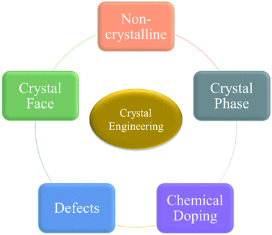
Electrochemical water splitting to produce hydrogen is a potential method for generating high-purity hydrogen on a large scale. The two half reactions of water splitting which are the oxygen evolution reaction (OER) at the anode and the hydrogen evolution reaction (HER) at the cathode1–5 are kinetically sluggish, especially the former one, calling for efficient catalysts to lower the energy barriers of the reactions and hence to accelerate the reaction kinetics and reduce the energy loss. Though IrO2 and RuO2 are the most efficient and commercialized OER catalysts, the shortage in resources and high costs severely limit their large-scale utilization. Therefore, more interest and attention have been paid to explore and develop non-precious metal-based electrocatalysts such as transition metal based compounds,6–13 which have unique electronic and magnetic properties and are widely used in the fields of catalysis, magnetics, cancer treatment, etc.14–20 For catalysis, the catalytic performance of transition metal based compounds is strongly dependent on their crystallographic structures, which can influence the coordination environments, electronic arrangement of the transition metal ions, and the surface binding energy of the compounds with reaction intermediates.9,21 Till now, tremendous efforts and much progress has been made on phase engineering,22–25 surface engineering26–28 and structural control29,30 to modulate these factors and hence to enhance the catalytic performance of the catalysts. Moreover, many review papers have also been published on transition metal based electrocatalysts for water splitting from various viewpoints such as chemical composition, morphology, synthesis methods, etc. However, these reviews provided little discussion from the perspective of crystal engineering, which we believe is critical for the design and synthesis of catalytic nanomaterials. Therefore, in this perspective, we will summarize the recent progress on transition metal based catalysts for water splitting with emphasis on crystal engineering, including the effects of crystalline phases, surfaces, lattice distortion caused by doping or creating defects on the catalytic activity of the catalysts (Fig. 1). In the final section, current challenges and guidelines for solving the crystal engineering problems for efficient electrocatalytic water splitting will be provided. We hope this perspective will draw more attention and interest in pushing the crystal engineering of transition metal based catalysts for enhancing their catalytic performance to a new level towards water splitting.2. Influence of the atomic structure and atomic order
According to the microscopic arrangement of atoms inside a solid material, a material can be defined as a crystal if the atoms are in a periodic arrangement. However, for most catalysts that are composed of nano-building blocks, though the final blocks are small crystals with periodic arrangement of atoms, the whole material is not periodically arranged because of the existence of grain boundaries. In other words, most of the nano-catalysts are polycrystals or mesocrystals, rather than the so-called single crystals. When the building blocks with ordered atomic arrangement are small enough, no diffraction peaks can be found, and in that case, this kind of material would exhibit non-crystalline character with only a short-range order. Then if the individual building blocks are also in a random arrangement of atoms, the whole catalyst is then in an amorphous phase, in which there is no periodic atomic arrangement.Therefore, in this section, we will discuss transition metal based compounds as electrocatalysts for water splitting by dividing them into amorphous and crystallized ones with completely different crystal phases.
2.1 Non-crystalline catalysts
Due to the disordered atomic arrangement, amorphous catalysts often have abundant dangling bonds. Therefore, the surface energy of an amorphous material is relatively high, leading to the remodeling and relaxation of the surface by adsorbing other atoms or molecules, which would benefit the adsorption processes of catalytic reactions.31–33 Therefore, many studies have been conducted to create amorphous layers on the surface of catalysts. For example, Liu et al.34 loaded amorphous cobalt sulfides onto Cu/CF. The as-formed Cu@CoSx/CF showed advanced bifunctional catalytic performance on both the HER and OER, which was even comparable to that of coupled noble metal catalyst Pt/C–IrO2. Considering that the majority of crystalline catalysts with more than a single metal ion show better catalytic performance, there were anticipated advantages to developing amorphous metal oxides with multiple metal elements. However, most of the amorphous metal oxides were synthesized by electrodeposition methods, which could not realize the formation of amorphous mixed metal oxides and could not translate to every metal. Therefore, Smith et al.35 innovatively designed a photochemical metal–organic deposition (PMOD) method that could achieve the production of various mixed metal oxides in the amorphous phase. As expected, the prepared amorphous iron oxide, cobalt oxide, nickel oxides and iron–cobalt–nickel oxides with different atomic ratios of Fe/Co/Ni showed a much better OER performance than the crystallized Fe2O3. Besides the planar film structure with nanoparticles as the building blocks, recently, an amorphous NiFeCo LDH/NF catalyst with a porous 2D nanosheet structure was reported using an electrodeposition method on nickel foam, which also presented good OER performance because of the advantages of the amorphous phase of the material.36Though adsorption processes would easily occur on the surface of amorphous catalysts due to the existence of many dangling bonds that make the surface energy quite high, they also increase the space resistance of change transport, and hence deteriorate the conductivity of the catalysts against the catalytic reaction. Nevertheless, the crystallized catalysts have advantages in electrical conductivity. Therefore, rationally combining the two structures to maximize the water splitting efficiency is of great significance.
Recently, a hybrid catalyst NiCo2O4@NixCoy LDH with a core–shell structure was grown on nickel foam (NF), in which amorphous NixCoy LDH and a crystallized 3D NiCo2O4 nanowall acted as the shell and core, respectively, as shown in Fig. 2a. The XRD pattern of the as-synthesized hybrid structure is shown in Fig. 2b. The vertically aligned structure and porous properties of the NiCo2O4 nanowall provided large surface area with abundant active sites and ensured good electrical conductivity. And the amorphous NixCoy LDH facilitated the adsorption of intermediates such as HO*, O*, and HOO* during the reaction. Therefore, the hybrid catalyst NiCo2O4@NixCoy LDH showed advanced OER performance (Fig. 2c).37
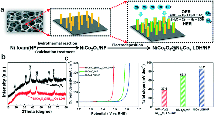 | ||
| Fig. 2 Hybrid catalyst NiCo2O4@NixCoy LDH/NF with amorphous NixCoy LDH and crystallized NiCo2O4 as the shell and core, respectively.37 (a) Illustration of the fabrication process of the hybrid catalyst, (b) XRD of NiCo2O4 and NiCo2O4@Ni0.796Co LDH; (c) polarization curves and Tafel slopes of NiCo2O4@Ni0.796Co LDH/NF, NiCo LDH/NF, and NiCo2O4/NF. | ||
Actually, many researchers have found that crystallized catalysts would transform into the amorphous phase, especially the surface layer, during the OER process, which in turn enhanced the catalytic performance of the catalyst.38 Therefore, researchers tried to intentionally convert the crystallized catalysts to the morphology retained amorphous ones in order to increase their catalytic activity.7 For example, by selectively dissolving La and depositing Fe into the LaNi perovskite precursor, Chen et al.39 successfully constructed an amorphous LaNiFe hydroxide. The as-synthesized amorphous hydroxide showed a Ni3+-based edge-sharing octahedral framework, which was surrounded by a distorted Fe octahedron in the interstices. The dual active sites of both Ni and Fe, the enlarged specific surface area, and the amorphous character made the LaNiFe hydroxide an advanced OER catalyst with a low overpotential of 189 mV at 10 mA cm−2 and a small Tafel slope of 36 mV dec−1. Further, Zhang et al.40 synthesized a fluoride (F−)-incorporated NiFe hydroxide (NiFe–OH–F) nanosheet array. Then they leached out a significant amount of F− ions via the electrochemical processes under OER conditions, which triggered surface self-reconstruction and converted the original crystallized NiFe–OH–F into surface-reconstructed porous metal oxide (NiFe–OH–F-SR) that was in the amorphous phase. The unique hierarchical framework of NiFe–OH–F-SR exposed large specific surface areas with more catalytic active sites, leading to good catalytic performance in water oxidation with a low overpotential of 176 mV (10 mA cm−2) and an extremely small Tafel slope of 22.6 mV dec−1.
As mentioned above, there are many materials without visible diffraction peaks but still show some periodic characters in a short range. These materials are simply called “amorphous” ones, especially those observed on the surface of catalysts during catalytic processes that undergo surface reconstruction.40–43 Rather than amorphous catalysts, here non-crystalline catalysts would be a more appropriate name. Similar to amorphous materials, this kind of non-crystalline catalyst also has high surface energy and hence easily adsorbs foreign atoms/molecules to trigger the catalytic process. However, rather than the indiscriminate adsorption properties of amorphous catalysts, the non-crystalline catalysts with a short range order could show selective adsorption due to the large exposed surface area. Unfortunately, little work has been conducted on investigating the effects of surface and grain size of the small domains on the catalytic performance towards water splitting, probably due to the low availability of advanced characterization techniques. Therefore, developing in situ, operando and surface sensitive techniques to track the atomic-scale structural evolution of catalysts during electrocatalytic operation is critically important.
2.2 Crystallized catalysts with different crystal phases
As we all know, a compound usually has many different crystal phases. For example, manganese dioxide (MnO2) has six crystal phases44 and molybdenum disulfide (MoS2) has two crystal phases of 1T and 2H.25 Different crystal phases indicate distinct coordination numbers and coordination environments of transition metal ions, hence rendering the compounds different catalytic performances. Ni et al.22 reported a facile electrodeposition method for controlled synthesis of nickel selenide nanosheets with different crystal phases. At deposition potentials of −0.35, −0.46, and −0.60 V, pure NiSe2, NiSe, and Ni3Se2 were obtained, respectively (Fig. 3a and b). The mixtures of NiSe/Ni3Se2 and NiSe2/NiSe could also be synthesized at potentials ranging from −0.46 to −0.60 V and from −0.46 V to −0.35, respectively. Through a series of studies, they found that nickel selenide presented distinct phase-dependent electrocatalytic activities for both the OER and HER. Among all the synthesized nickel selenide, NiSe2 with a large electrochemical active surface area and good conductivity exhibited the best OER and HER performances with a low overpotential of 104 mV (10 mA cm−2) for the HER (Fig. 3c) and 279 mV (20 mA cm−2) for the OER (Fig. 3d).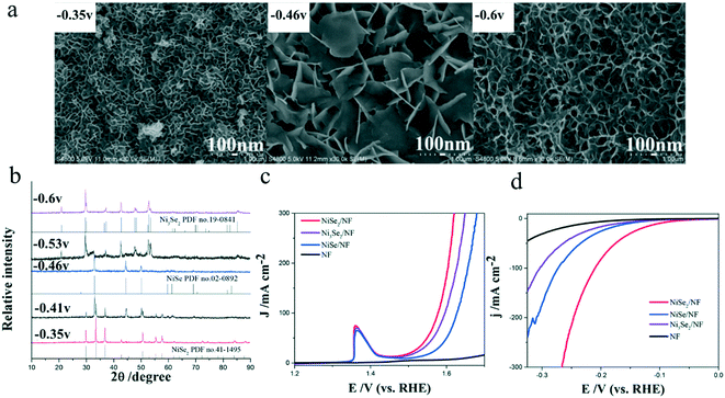 | ||
| Fig. 3 Controlled synthesis of nickel selenides in different crystal phases.22 (a) FESEM images of the as-prepared nickel selenides with different crystal phases taken at various deposition potentials: −0.35, −0.46, and −0.60 V; (b) XRD patterns of the nickel selenides; (c and d) polarization curves of these nickel selenides for (c) HER and (d) OER. | ||
Knowing that one crystal phase of a compound would be more beneficial to the catalytic reactions, researchers have attempted to synthesize catalysts with particular phases. Layered double hydroxides (LDHs) and metal–organic frameworks (MOFs) have been applied as precursors to synthesize transition metal based compounds, which then could be phase-converted to the final products with other crystal phases by calcination treatments, providing them with high conductivity and abundant active sites that benefit the water splitting reactions.23,24,45,46 For example, Long et al.23 applied FeNi layered double hydroxide (FeNi-LDH) nanosheets that were excellent OER catalysts as precursors, and prepared β-iron–nickel sulfide (β-INS) ultra-thin nanosheets by topological transformation, which showed a good HER activity. Further, the β-INS ultrathin nanosheets were converted to α-INS by a simple annealing treatment, and the nanosheet structure was inherited (Fig. 4a). The corresponding XRD patterns of α- and β-INS nanosheets are shown in Fig. 4b. α-INS showed a resistivity 2 orders of magnitude smaller than β-INS. Therefore, α-INS with an intrinsic metallic character and retained nanosheet microstructure showed a good HER catalytic performance with a low overpotential of only 105 mV at 10 mA cm−2 (Fig. 4c) and a small Tafel slope of 40 mV dec−1 (Fig. 4d).
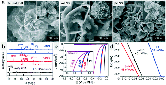 | ||
| Fig. 4 Morphology retained phase-conversion from LDH to β-INS and α-INS sulfides.23 (a) SEM images of the FeNi LDH precursor, β-INS nanosheets, and metallic α-INS nanosheets. (b) XRD pattern of the LDH precursor, β-INS and α-INS. (c) Linear sweep voltammetry (LSV) curves of the β-NiS, β-INS, and α-INS catalyzed HER. (d) Tafel plots of the Pt, β-INS, and α-INS catalyzed HER. | ||
Further, Chen et al.24 reported cubic phase CoSe2 (c-CoSe2), made by phase transformation from orthorhombic CoSe2 (o-CoSe2). By investigating the relationship between Co–Se bond lengths with adsorbed H atoms (Hads) and water adsorption energy, they found that c-CoSe2 showed a lower water adsorption energy, in conjunction with a high conductivity, it exhibited superior HER catalytic activity in alkaline media. The overpotential of c-CoSe2 for delivering a current density of 10 mA cm−2 was only 190 mV, much smaller than 270 mV and 510 mV for o-CoSe2/CC and Co(OH)F/CC. Meanwhile, the Tafel slope of c-CoSe2/CC was 85 mV dec−1, also lower than that of o-CoSe2/CC (120 mV dec−1) and Co(OH)F/CC (310 mV dec−1), indicating the efficiency of phase controlling for improving the catalytic performance of a catalyst.
Interestingly, phase transformation would occur when the compounds adsorbed another species.47–50 Wei et al.25 have found that the adsorption of Ir atoms on MoS2 could trigger the phase transition of MoS2 from 2H to 1T. Theoretically, they found that with the increase of adsorbed Ir atom concentration, the total energy difference between Ir/2H-MoS2 and Ir/1T-MoS2 (ΔET–H) decreased, which even became negative when the concentration of the Ir atom increased to above 20% (Fig. 5a and b), indicating that Ir/1T-MoS2 was more stable than Ir/2H-MoS2. This was also observed experimentally. More importantly, the as-formed Ir/1T-MoS2 catalysts exhibited excellent catalytic activity for both the HER (−44 mV at 10 mA cm−2, 32 mV dec−1) and OER (330 mV at 10 mA cm−2, 44 mV dec−1) in 1.0 M KOH (Fig. 5c–f). The improved electrical conductivity and activated basal plane arising from the phase transformation of MoS2 from the 2H-phase to 1T-phase, as well as the modified surface hydrophilicity due to the adsorbed uniformly distributed Ir atoms were proposed to be the critical reason for the enhanced bifunctional performance of Ir/1T-MoS2.
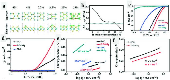 | ||
| Fig. 5 Phase conversion triggered by adsorbing Ir atoms.25 Theoretical model (a) and energy differences (b) between Ir/1T-MoS2 and Ir/2H-MoS2 as a function of the atomic concentration of the adsorbed Ir. (c) LSV curves of the different catalysts for the HER tested in 1.0 M KOH. (d) LSV curves of the different catalysts for the OER tested in 1.0 M KOH. (e and f) Tafel plots of the different catalysts for the HER and OER calculated by extrapolation methods. | ||
As we know, high-index crystal faces often have unique properties when compared with thermodynamic stable faces.51–53 By creating unusual crystal faces of a particular catalyst crystal, many interesting results could be observed. Yang et al.54 reported vertical arrays of H bonding on the stepped edge surface MoS2 (se-MoS2) sheets terminated with a stepped surface structure. The synthesis procedure and the corresponding HRTEM images of se-MoS2 are shown in Fig. 6a and b. Though MoS2 showed good HER activity in acidic electrolyte, it exhibited little HER activity in alkaline solutions. However, the as-prepared se-MoS2 with a stepped surface structure showed an outstanding HER performance with an overpotential of 104 mV for achieving a current density of 10 mA cm−2 in strong alkaline solution (Fig. 6c), and the impedance was significantly reduced (Fig. 6d), due to the unique vertically terminated and highly exposed stepped surface structure that rendered a nearly thermos-neutral H- adsorption energy.
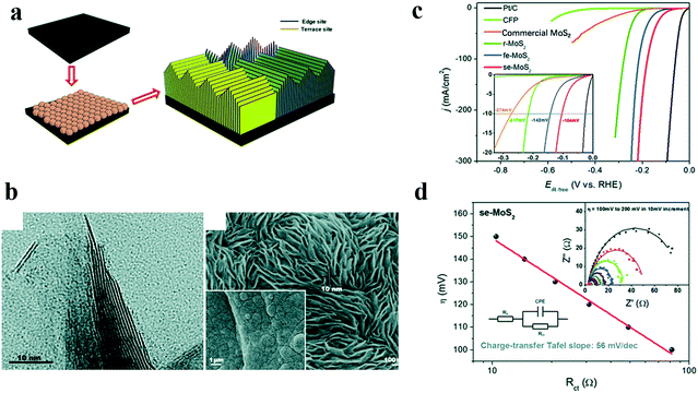 | ||
| Fig. 6 Effects of high index faces on the catalytic performance of MoS2.54 (a) Schematic illustration of stepped edge surface-terminated MoS2 arrays (se-MoS2), (b) HRTEM image of the se-MoS2 layers showing that the crystal fringes of the S–Mo–S layers along the edge are stepped, (c) polarization curves and (d) charge-transfer Tafel plots of se-MoS2 and control catalysts. | ||
3. Local lattice distortion
Besides the crystal phases, chemical doping and creating defects in a crystal could also change the coordination environments of transition metal ions, thus influencing the catalytic performance of the catalysts. In this section, we will discuss the strategies of chemical doping and defect creation on transition metal based catalysts for improving their catalytic performance towards water oxidation and reduction.3.1 Chemical doping
Chemical doping has been found to be an effective method to modify the electronic structures of transition metal ions, which could modulate the intrinsic activity of catalysts.20,55–59 As a typical example, nickel hydroxide (Ni(OH)2) shows little catalytic activity toward water oxidation, however, after iron doping, the as-formed NiFe LDH has been found to be an excellent OER catalyst in alkaline solutions, due to the so-called synergistic effects between the two transition metal ions.60Further, a third transition metal ion was also incorporated into LDH, especially NiFe LDH to enhance the synergistic effects of metal ions and hence improve their catalytic performance towards the OER. Long et al.61 introduced Co into NiFe LDH and tuned the atomic ratios of the three transition metal ions. They found that with the increase of Co concentration, the thickness of the prepared NiCoFe LDH decreased, enlarging the specific surface area and increasing the catalytic active sites, and hence improving the OER performance. Later, Li et al.62 doped vanadium into NiFe LDHs to synthesize NiFeV LDHs by a hydrothermal method. The as-synthesized NiFeV LDHs showed excellent OER catalytic performance with an overpotential at 20 mA cm−2 as low as 195 mV, and the Tafel slope was as small as 42 mV dec−1 for the OER. The narrowed bandgap of NiFeV LDHs exhibited enhanced conductivity, which promoted OER activity. Till now, many tri-metal LDHs have been successfully synthesized and showed good water splitting performance, including NiFeZn, NiCoZn, NiFeCu, NiFeMn, NiCo(II)Co(III) LDH, etc.63–65 Recently, Liu et al.66 reported that the basal plane of NiFe LDH could be activated by introducing Mn ions that has a weak electronegativity/high reducing ability into the lattice of NiFe-LDH. DFT calculations showed that the electron density of both Ni2+ and Fe3+ increased after Mn2+ doping (Fig. 7a) and the electron-rich Ni2+ and Fe3+ sites in MnNiFe LDH showed a positive impact in the water oxidation (Fig. 7b). These results indicated that the electron transferred from Mn2+ with strong reducing ability to surrounding Ni2+ and Fe3+, leading to electron-rich Ni2+ and Fe3+, which would facilitate the deprotonation step of the OER and hence improve its water oxidation performance. This assumption was verified experimentally. The as-synthesized MnNiFe-LDH showed a quite low onset potential of 1.41 V (vs. RHE) and fast reaction kinetics (Fig. 7c).
 | ||
| Fig. 7 Activating the basal plane of LDH for water oxidation.66 (a) Schematic structure and electron density evolution based on DFT calculations, (b) four-electron mechanism of the oxygen evolution reaction and Gibbs free energy evolution based on DFT calculations, and (c) cyclic voltammetry (CV) of different catalysts for the OER tested. | ||
Besides transition metal based LDHs, increased catalytic performance by doping has also been found in alloy catalysts, such as Ru doped Co with a core–shell structure which exhibited a greatly enhanced character on carbon–hydrogen bonding, leading to better HER properties than its single counterpart Co.67 In addition, similar results have been found in metal phosphide68,69 and metal sulfide70 catalysts as well. The catalytic performance of phosphides and sulfides with multiple transition metal ions were much better than their single metal phosphides/sulfides counterparts. For example, Xiong et al.71 synthesized a Co doped MoS2, which showed an advanced bifunctional performance for the whole water splitting reaction, with low overpotentials at current densities of 10, 100, and 200 mA cm−2 of 48, 132, 165 mV and 260, 350, 390 mV, for the HER and OER, respectively. From the theoretical calculations, the authors found that the original MoS2 precursor had semiconductor properties with a bandgap of ≈1.70 eV, while the Co-doped MoS2 had a bandgap of ≈0 eV, indicating a metallic character that benefited the electrocatalysis process.
In addition to multiple metals, non-metal elements have also been substituted to realize doping. Jin et al. reported a CoPS catalyst for the HER, by doping P into CoS2 with a pyrite structure.72 The as-prepared ternary pyrite-type CoPS worked as a high performance noble metal free electrocatalyst for electrochemical hydrogen production with a low overpotential of 48 mV for achieving a geometrical current density of 10 mA cm−2 and long-term stability. The advanced catalytic performance of CoPS was proposed to result from the idealized hydrogen adsorption energy of the catalytic sites by tuning the electronic structure and reactivity after P doping.
3.2 Defect engineering
Defects including both cation and anion vacancies could directly affect the coordination number of transition metal ions, hence influencing their catalytic performance. Early in 2014, Kim et al.73 reported an oxygen-deficient perovskite Ca2Mn2O5 that worked as an efficient OER catalyst via a reductive annealing method (Fig. 8a and b). The unit cell structure of Ca2Mn2O5 was different from CaMnO3 because of the ordered oxygen vacancy (Fig. 8c), which could facilitate the OER process, providing it with good OER activity (Fig. 8d–f). Then many efforts have been made on the defect creation on catalysts to enhance their catalytic performance. Soon after, Islam et al.74 reported rutile MnO2 with many surface vacancies, which showed high electrochemical and good catalytic performance. Later, the Xie group made much progress on fabricating oxygen vacancies in many electrocatalysts such as ultrathin indium oxide sheets75 and spinel structured nanosheets76 and found the enhanced OER catalytic activity of these materials.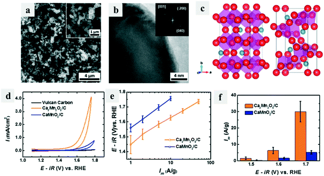 | ||
| Fig. 8 Oxygen-deficient perovskite Ca2Mn2O5 for the OER.73 (a) SEM and (b) HRTEM and FFT (inset) images of Ca2Mn2O5; (c) unit cell structures of CaMnO3 (left) and Ca2Mn2O5 (right); (d) iR-corrected data of Ca2Mn2O5/C, CaMnO3/C, and Vulcan carbon XC-72; (e) Tafel plot of mass activities; (f) mass activities at various applied potentials. | ||
The Wang group applied plasma technology to fabricate defects by making nano- or micro-pores on many transition metal based electrocatalysts for water splitting.77–81 The greatly increased number of catalytic active sites around the defects promoted the performance of the catalysts. Besides the oxygen vacancies, recently, Yang et al.82 reported an ionic reductive complexation extraction (IRCE) method to create atomically dispersed cation vacancies in NiCu LDH, making the catalytically inactive NiCu LDH an excellent electrocatalyst for the OER. This work provides another promising direction for creating defects on catalysts to modulate the intrinsic catalytic activity and charge transfer of catalysts.
4. Summary and outlook
In this review, we have selected the representative studies in recent years to illustrate the influence of the crystalline properties of catalysts on their electrocatalytic performance in water splitting reactions from the perspective of crystal engineering. Mainly summarized and discussed are the effects of atomic structure and atom entity, and the influences of crystalline phases, exposed crystal surfaces, and local lattice distortion via chemical doping/defect engineering on the electrocatalytic water splitting performance. Though non-crystalline catalysts usually show excellent adsorbing properties due to the existence of dangling bonds, bonding distortion, more active sites and better surface exposure, they suffer from the poor charge transfer properties and oftentimes also the peculiar micro-morphologies that go against their catalytic performance. For crystallized catalysts, the phase and crystalline surface control directly influence the coordination number, coordination environments, and the electronic structure of transition metal ions, thereby determining the catalytic performance of these materials. Through rational design to achieve chemical doping or defect engineering in the crystallized catalysts, one could effectively modulate the coordination and electronic structure of the transition metal ions and cations and accordingly, control their catalytic activity.Though much progress has been made in crystal engineering of catalysts for improving their performance in electrochemical water splitting, there are also many unsolved problems and challenges. First, how do the dangling bonds on the surface of amorphous catalysts engage in adsorbing and desorbing the intermediates of the OER and HER? How do the grain size and their surface influence the selective adsorption of reactants? How can we rationally design more effective dangling bonds at particular sites of the catalyst to realize the selective reaction? Secondly, how do the OER and HER occur on different faces of the crystallized catalysts, and what's the relationship between the coordination number of transition metal ions and their catalytic performance? Third, what's the role of dopants and defects in enhancing the catalytic activity, and how are they involved in the reaction process? Last but not least, how can we combine the merits of non-crystalline and crystallized transition metal based catalysts to realize the high-efficiency hydrogen production by electrocatalytic water splitting? To tackle these challenges, more ingeniously designed experiments, theoretical simulations and elaborate techniques for obtaining in situ or real time information on water splitting reactions and the catalytic processes are greatly needed.
Conflicts of interest
There are no conflicts to declare.Acknowledgements
This work was financially supported by the Shenzhen Peacock Plan (KQTD2016053015544057), the Shenzhen Science and Technology Innovation Commission (JCYJ20180302153417057), the Nanshan Pilot Plan (LHTD20170001), the Natural Science Foundation of China (21703003, 21972006), the Guangdong Science and Technology Program (2017B030314002), and the NSFC/Hong Kong RGC Research Scheme (N_HKUST610/14).Notes and references
- I. Concina, Z. H. Ibupoto and A. Vomiero, Adv. Eng. Mater., 2017, 7, 1700706 Search PubMed.
- T. N. J. I. Edison, R. Atchudan, N. Karthik and Y. R. Lee, Int. J. Hydrogen Energy, 2017, 42, 14390–14399 CrossRef.
- M. S. Burke, L. J. Enman, A. S. Batchellor, S. Zou and S. W. Boettcher, Chem. Mater., 2015, 27, 7549–7558 CrossRef CAS.
- N.-T. Suen, S.-F. Hung, Q. Quan, N. Zhang, Y.-J. Xu and H. M. Chen, Chem. Soc. Rev., 2017, 46, 337–365 RSC.
- R. Atchudan, T. N. J. I. Edison, S. Perumal, M. Shanmugam and Y. R. Lee, J. Mol. Liq., 2018, 268, 343–353 CrossRef CAS.
- K. A. Stoerzinger, O. Diaz-Morales, M. Kolb, R. R. Rao, R. Frydendal, L. Qiao, X. R. Wang, N. B. Halck, J. Rossmeisl, H. A. Hansen, T. Vegge, I. E. L. Stephens, M. T. M. Koper and Y. Shao-Horn, ACS Energy Lett., 2017, 2, 876–881 CrossRef CAS.
- L. C. Seitz, C. F. Dickens, K. Nishio, Y. Hikita, J. Montoya, A. Doyle, C. Kirk, A. Vojvodic, H. Y. Hwang, J. K. Norskov and T. F. Jaramillo, Science, 2016, 353, 1011–1014 CrossRef CAS.
- X. Long, Z. Wang, S. Xiao, Y. An and S. Yang, Mater. Today, 2016, 19, 213–226 CrossRef CAS.
- Z. Wang, X. Long and S. Yang, ACS Omega, 2018, 3, 16529–16541 CrossRef CAS PubMed.
- J. Hu, C. Zhang, X. Meng, H. Lin, C. Hu, X. Long and S. Yang, J. Mater. Chem. A, 2017, 5, 5995–6012 RSC.
- X. Long, H. Lin, D. Zhou, Y. An and S. Yang, ACS Energy Lett., 2018, 3, 290–296 CrossRef CAS.
- X. Long, W. Qiu, Z. Wang, Y. Wang and S. Yang, Mater. Today Chem., 2019, 11, 16–28 CrossRef CAS.
- L. Lv, Z. Yang, K. Chen, C. Wang and Y. Xiong, Adv. Eng. Mater., 2019, 9, 1803358 Search PubMed.
- B. Su, Z. C. Cao and Z. J. Shi, Acc. Chem. Res., 2015, 48, 886–896 CrossRef CAS.
- S. Leenders, R. Gramage-Doria, B. de Bruin and J. N. H. Reek, Chem. Soc. Rev., 2015, 44, 433–448 RSC.
- T. J. Greenfield, M. Julve and R. P. Doyle, Coord. Chem. Rev., 2019, 384, 37–64 CrossRef CAS.
- M. Hoop, A. S. Ribeiro, D. Rosch, P. Weinand, N. Mendes, F. Mushtaq, X. Z. Chen, Y. Shen, C. F. Pujante, J. Puigmarti-Luis, J. Paredes, B. J. Nelson, A. P. Pego and S. Pane, Adv. Funct. Mater., 2018, 28, 1705920 CrossRef.
- S. G. Wang, X. Li, Y. Chen, X. J. Cai, H. L. Yao, W. Gao, Y. Y. Zheng, X. An, J. L. Shi and H. R. Chen, Adv. Mater., 2015, 27, 2775–2782 CrossRef CAS PubMed.
- B. Su, Z.-C. Cao and Z.-J. Shi, Acc. Chem. Res., 2015, 48, 886–896 CrossRef CAS.
- J. Yu, Q. Cao, Y. Li, X. Long, S. Yang, J. K. Clark, M. Nakabayashi, N. Shibata and J.-J. Delaunay, ACS Catal., 2019, 9, 1605–1611 CrossRef CAS.
- Z. Wang, T. Liu, X. Long, Y. Li, F. Bai and S. Yang, J. Phys. Chem. C, 2019, 123, 9282–9291 CrossRef CAS.
- J. Zhu and Y. Ni, CrystEngComm, 2018, 20, 3344–3352 RSC.
- X. Long, G. Li, Z. Wang, H. Zhu, T. Zhang, S. Xiao, W. Guo and S. Yang, J. Am. Chem. Soc., 2015, 137, 11900–11903 CrossRef CAS PubMed.
- P. Chen, K. Xu, S. Tao, T. Zhou, Y. Tong, H. Ding, L. Zhang, W. Chu, C. Wu and Y. Xie, Adv. Mater., 2016, 28, 7527–7532 CrossRef CAS PubMed.
- S. Wei, X. Cui, Y. Xu, B. Shang, Q. Zhang, L. Gu, X. Fan, L. Zheng, C. Hou, H. Huang, S. Wen and W. Zheng, ACS Energy Lett., 2018, 4, 368–374 CrossRef.
- Y. P. Zhu, C. Guo, Y. Zheng and S.-Z. Qiao, Acc. Chem. Res., 2017, 50, 915–923 CrossRef CAS PubMed.
- Q. Zhou, J. Pu, X. Sun, C. Zhu, J. Li, J. Wang, S. Chang and H. Zhang, J. Mater. Chem. A, 2017, 5, 14873–14880 RSC.
- P. F. Liu, L. Zhang, L. R. Zheng and H. G. Yang, Mater. Chem. Front., 2018, 2, 1725–1731 RSC.
- X. Wang, A. Vasileff, Y. Jiao, Y. Zheng and S.-Z. Qiao, Adv. Mater., 2019, 31, 1803625 CrossRef PubMed.
- J. Yang, L. Wei, T. Zhao, T. Yang, J. Wang, W. Wu, X. Yang, Z. Li and M. Wu, Electrochim. Acta, 2019, 318, 949–956 CrossRef CAS.
- A. Indra, P. W. Menezes, N. R. Sahraie, A. Bergmann, C. Das, M. Tallarida, D. Schmeisser, P. Strasser and M. Driess, J. Am. Chem. Soc., 2014, 136, 17530–17536 CrossRef CAS PubMed.
- R. D. L. Smith, M. S. Prevot, R. D. Fagan, Z. Zhang, P. A. Sedach, M. K. J. Siu, S. Trudel and C. P. Berlinguette, Science, 2013, 340, 60–63 CrossRef CAS PubMed.
- A. Basu, A. N. Samant, S. P. Harimkar, J. D. Majumdar, I. Manna and N. B. Dahotre, Surf. Coat. Technol., 2008, 202, 2623–2631 CrossRef CAS.
- Y. Liu, Q. Li, R. Si, G.-D. Li, W. Li, D.-P. Liu, D. Wang, L. Sun, Y. Zhang and X. Zou, Adv. Mater., 2017, 29, 1606200 CrossRef PubMed.
- R. D. L. Smith, M. S. Prevot, R. D. Fagan, Z. P. Zhang, P. A. Sedach, M. K. J. Siu, S. Trudel and C. P. Berlinguette, Science, 2013, 340, 60–63 CrossRef CAS PubMed.
- P. Babar, A. Lokhande, V. Karade, B. Pawar, M. G. Gang, S. Pawar and J. H. Kim, ACS Sustainable Chem. Eng., 2019, 7, 10035–10043 CrossRef CAS.
- M. Li, L. Tao, X. Xiao, X. Jiang, M. Wang and Y. Shen, ACS Sustainable Chem. Eng., 2019, 7, 4784–4791 CrossRef CAS.
- C. Walter, P. W. Menezes, S. Orthmann, J. Schuch, P. Connor, B. Kaiser, M. Lerch and M. Driess, Angew. Chem., Int. Ed., 2018, 57, 698–702 CrossRef CAS PubMed.
- G. Chen, Y. Zhu, H. M. Chen, Z. Hu, S. F. Hung, N. Ma, J. Dai, H. J. Lin, C. T. Chen, W. Zhou and Z. Shao, Adv. Mater., 2019, 31, 1900883 CrossRef PubMed.
- B. Zhang, K. Jiang, H. Wang and S. Hu, Nano Lett., 2018, 19, 530–537 CrossRef PubMed.
- A. Bergmann, T. E. Jones, E. M. Moreno, D. Teschner, P. Chernev, M. Gliech, T. Reier, H. Dau and P. Strasser, Nat. Catal., 2018, 1, 711–719 CrossRef CAS.
- A. Bergmann, E. Martinez-Moreno, D. Teschner, P. Chernev, M. Gliech, J. F. de Araujo, T. Reier, H. Dau and P. Strasser, Nat. Commun., 2015, 6, 8625 CrossRef CAS PubMed.
- H. Jiang, Q. He, X. Li, X. Su, Y. Zhang, S. Chen, S. Zhang, G. Zhang, J. Jiang, Y. Luo, P. M. Ajayan and L. Song, Adv. Mater., 2019, 31, e1805127 CrossRef PubMed.
- R. Pokhrel, M. K. Goetz, S. E. Shaner, X. Wu and S. S. Stahl, J. Am. Chem. Soc., 2015, 137, 8384–8387 CrossRef CAS PubMed.
- J. Gao, L. Liu, H.-J. Qiu and Y. Wang, Nanotechnology, 2017, 28, 31 Search PubMed.
- H. Liang, L. Li, F. Meng, L. Dang, J. Zhuo, A. Forticaux, Z. Wang and S. Jin, Chem. Mater., 2015, 27, 5702–5711 CrossRef CAS.
- P. Hao, W. Zhu, L. Li, Y. Xin, J. Xie, F. Lei, J. Tian and B. Tang, Chem. Commun., 2019, 55, 10138–10141 RSC.
- X. Shi, M. Fields, J. Park, J. M. McEnaney, H. Yan, Y. Zhang, C. Tsai, T. F. Jaramillo, R. Sinclair, J. K. Norskov and X. Zheng, Energy Environ. Sci., 2018, 11, 2270–2277 RSC.
- S. Wei, X. Cui, Y. Xu, B. Shang, Q. Zhang, L. Gu, X. Fan, L. Zheng, C. Hou, H. Huang, S. Wen and W. Zheng, ACS Energy Lett., 2019, 4, 368–374 CrossRef CAS.
- Z. Dai, H. Geng, J. Wang, Y. Luo, B. Li, Y. Zong, J. Yang, Y. Guo, Y. Zheng, X. Wang and Q. Yan, ACS Nano, 2017, 11, 11031–11040 CrossRef CAS PubMed.
- X. Liu, J. Liu, Z. Chang, X. Sun and Y. Li, Catal. Commun., 2011, 12, 530–534 CrossRef CAS.
- H. Zhang, Y. Lu, C. Guan, N. Song, Y. Zhang, H. Liu and J. Fang, J. Mater. Chem. C, 2017, 5, 645–653 RSC.
- Y. Liu, D. Huang, H. Liu, T. Li and J. Wang, Cryst. Growth Des., 2019, 19, 2758–2764 CrossRef CAS.
- J. Hu, B. Huang, C. Zhang, Z. Wang, Y. An, D. Zhou, H. Lin, M. K. H. Leung and S. Yang, Energy Environ. Sci., 2017, 10, 593–603 RSC.
- T. Tang, W.-J. Jiang, S. Niu, N. Liu, H. Luo, Y.-Y. Chen, S.-F. Jin, F. Gao, L.-J. Wan and J.-S. Hu, J. Am. Chem. Soc., 2017, 139, 8320–8328 CrossRef CAS PubMed.
- H. Jiang, J. Gu, X. Zheng, M. Liu, X. Qiu, L. Wang, W. Li, Z. Chen, X. Ji and J. Li, Energy Environ. Sci., 2019, 12, 322–333 RSC.
- Y. Guo, P. Yuan, J. Zhang, H. Xia, F. Cheng, M. Zhou, J. Li, Y. Qiao, S. Mu and Q. Xu, Adv. Funct. Mater., 2018, 28, 1805641 CrossRef.
- X. Long, J. Li, S. Xiao, K. Yan, Z. Wang, H. Chen and S. Yang, Angew. Chem., Int. Ed., 2014, 53, 7584–7588 CrossRef CAS PubMed.
- X. Gao, X. Pan, X. Long and Z. Yi, J. Electrochem. Soc., 2017, 164, H755–H759 CrossRef CAS.
- D. A. Corrigan, J. Electrochem. Soc., 1987, 134, 377–384 CrossRef CAS.
- X. Long, S. Xiao, Z. Wang, X. Zheng and S. Yang, Chem. Commun., 2015, 51, 1120–1123 RSC.
- P. Li, X. Duan, Y. Kuang, Y. Li, G. Zhang, W. Liu and X. Sun, Adv. Eng. Mater., 2018, 8, 1703341 Search PubMed.
- Z. Liu, R. Ma, Y. Ebina, N. Iyi, K. Takada and T. Sasaki, Langmuir, 2007, 23, 861–867 CrossRef CAS PubMed.
- X. Wang, Y. Lin, Y. Su, B. Zhang, C. Li, H. Wang and L. Wang, Electrochim. Acta, 2017, 225, 263–271 CrossRef CAS.
- T. Wang, W. Xu and H. Wang, Electrochim. Acta, 2017, 257, 118–127 CrossRef CAS.
- D. Zhou, Z. Cai, Y. Jia, X. Xiong, Q. Xie, S. Wang, Y. Zhang, W. Liu, H. Duan and X. Sun, Nanoscale Horiz., 2018, 3, 532–537 RSC.
- J. Su, Y. Yang, G. Xia, J. Chen, P. Jiang and Q. Chen, Nat. Commun., 2017, 8, 14969 CrossRef PubMed.
- F. Zhang, Y. Ge, H. Chu, P. Dong, R. Baines, Y. Pei, M. Ye and J. Shen, ACS Appl. Mater. Interfaces, 2018, 10, 7087–7095 CrossRef CAS PubMed.
- Y. Wang, B. Kong, D. Zhao, H. Wang and C. Selomulya, Nano Today, 2017, 15, 26–55 CrossRef CAS.
- Z.-Z. Liu, X. Shang, B. Dong and Y.-M. Chai, J. Catal., 2018, 361, 204–213 CrossRef CAS.
- Q. Xiong, Y. Wang, P.-F. Liu, L.-R. Zheng, G. Wang, H.-G. Yang, P.-K. Wong, H. Zhang and H. Zhao, Adv. Mater., 2018, 30, 1801450 CrossRef PubMed.
- M. Caban-Acevedo, M. L. Stone, J. R. Schmidt, J. G. Thomas, Q. Ding, H.-C. Chang, M.-L. Tsai, J.-H. He and S. Jin, Nat. Mater., 2015, 14, 1245–1251 CrossRef CAS PubMed.
- J. Kim, X. Yin, K.-C. Tsao, S. Fang and H. Yang, J. Am. Chem. Soc., 2014, 136, 14646–14649 CrossRef CAS PubMed.
- D. A. Tompsett, S. C. Parker and M. S. Islam, J. Am. Chem. Soc., 2014, 136, 1418–1426 CrossRef CAS PubMed.
- L. Y. P. Luk, E. J. Loveridge and R. K. Allemann, J. Am. Chem. Soc., 2014, 136, 6862–6865 CrossRef CAS PubMed.
- J. Bao, X. Zhang, B. Fan, J. Zhang, M. Zhou, W. Yang, X. Hu, H. Wang, B. Pan and Y. Xie, Angew. Chem., Int. Ed., 2015, 54, 7399–7404 CrossRef CAS PubMed.
- L. Xu, Q. Jiang, Z. Xiao, X. Li, J. Huo, S. Wang and L. Dai, Angew. Chem., Int. Ed., 2016, 55, 5277–5281 CrossRef CAS PubMed.
- L. Tao, C.-Y. Lin, S. Dou, S. Feng, D. Chen, D. Liu, J. Huo, Z. Xia and S. Wang, Nano Energy, 2017, 41, 417–425 CrossRef CAS.
- L. Tao, X. Duan, C. Wang, X. Duan and S. Wang, Chem. Commun., 2015, 51, 7470–7473 RSC.
- Y. Wang, Y. Zhang, Z. Liu, C. Xie, S. Feng, D. Liu, M. Shao and S. Wang, Angew. Chem., Int. Ed., 2017, 56, 5867–5871 CrossRef CAS PubMed.
- Y. Wang, C. Xie, Z. Zhang, D. Liu, R. Chen and S. Wang, Adv. Funct. Mater., 2018, 28, 1703363 CrossRef.
- Y.-S. Xie, Z. Wang, M. Ju, X. Long and S. Yang, Chem. Sci., 2019, 10, 8354–8359 RSC.
Footnote |
| † These authors contributed equally to this work. |
| This journal is © The Royal Society of Chemistry 2020 |

