
Fixation of CO2 into cyclic carbonates catalyzed by ionic liquids: a multi-scale approach
Bao-Hua
Xu
,
Jin-Quan
Wang
,
Jian
Sun
,
Ying
Huang
,
Jun-Ping
Zhang
,
Xiang-Ping
Zhang
and
Suo-Jiang
Zhang
*
Beijing Key Laboratory of Ionic Liquids Clean Process, Key Laboratory of Green Process and Engineering, Institute of Process Engineering, Chinese Academy of Sciences, Beijing 100190, PR China. E-mail: sjzhang@home.ipe.ac.cn
First published on 4th November 2014
Abstract
Fixation of CO2 to cyclic carbonates is one of the most important reactions since it represents a much greener alternative to the traditional phosgene process. In this context, the transformation of CO2 with epoxides into cyclic carbonates with respect to the newly emerged ionic liquid (IL) technology is discussed from a multi-scale viewpoint, including (1) the mechanism considering the “cooperative effect” at the basic atom and molecule level; (2) the reactor configuration at the unit level; (3) and the related process integration at the system level.
1. Background
Establishing a chemical industry based on CO2 as a renewable C1 building block is a long-standing challenge, as well as a fascinating dream.1–3 At the present stage, although studies on fixation of CO2 into chemicals such as organic carbonates,4–6 urea derivatives,7 oxazolidinones,8 solar fuels9 and formic acid10 may not necessarily help mitigating the greenhouse effect, the significance should be attributed to the importance of utilizing a renewable feedstock responding to the call for a sustainable society. Unless the problems or uncertainties in the underlying principles of CO2 activation, the designing of appropriate reactors and the integration of the processes are well addressed, the goal of using CO2 as an environmentally friendly and economically feasible source of carbon could not be achieved.To date, CO2 has been found to be a synthon to react with small-member-ring compounds,4–6 amines,7 hydrogen,9,10 and so on for constructing C–C, C–O, C–N, C–H and C–M (metal) bonds. Particularly, the synthesis of cyclic carbonates via cycloaddition of CO2 to epoxides is one of the most effective routes for CO2 chemical fixation.2 The application of cyclic carbonates has been extended to many valuable cases,11 such as excellent aprotic polar solvents, electrolytes in secondary batteries, precursors for polycarbonates and other polymeric materials, and intermediates in the production of pharmaceuticals and fine chemicals like dialkylcarbonates, glycols, carbamates, pyrimidines, purines, etc. Numerous catalysts4–6 have been developed for their production by the coupling of CO2 with epoxides illustrated by alkali metal salts,12 metal oxides,13 transition metal complexes,14 Schiff bases,15 ion-exchange resins,16 functional polymers,17 quaternary ammonium and phosphonium salts,18 lanthanide oxychloride,19 and gold nanoparticles supported on resins.20 However, many of these catalyst systems suffered from low catalytic stability or reactivity, the need for co-solvents and extreme conditions, while newly emerged ionic liquid (IL) technology was supposed to solve such problems to some extent. In the last decade, extensive investigations on coupling of CO2 with epoxides for cyclic carbonate production using ILs as catalysts have been carried out and this greatly improved the understanding of how to activate CO2 and the inert C–O bond of epoxides effectively. Many of these studies have been the subject of several excellent recent reviews. We recommend these reviews to the readers and do not attempt to reproduce them here. For example, Sakakura et al. summarized nearly all of the existing synthetic technologies leading to organic carbonates, including both cyclic and acyclic carbonates. Catalysis by some traditional ILs for cyclic carbonates was there introduced briefly.4b In the later perspective article of Pescarmona et al.,4d various types of catalysts including ILs were presented and discussed critically together with an overview of the mechanisms with which catalysts operate and the parameters influencing their activity and selectivity. In terms of a specific issue on ILs, Arai et al. gave a view on the green synthesis of cyclic carbonates using ILs as catalysts or solvents from the following three aspects: catalytic reaction of CO2 and epoxides, electrochemical reaction of CO2 and epoxides and oxidative carboxylation of olefins.21a One year later, the progress in both fixation and chemical transformation of CO2 using ILs as absorbents and catalysts, accordingly, was summarized by Zhang et al.21b In this article, the significant advantages of the newly emerged IL technology were demonstrated compared with the traditional IL-free systems. Very recently, He et al. reviewed the new progress up to 2011 obtained in the task specific ILs (TSILs), which placed emphasis on the CO2 capture and utilization (CCU) rather than conventional CO2 capture and sequestration (CCS).21c
Although previous reviews are comprehensive, most of them focused on the diversity of IL catalysts/absorbents in mediating coupling of CO2 with various epoxides, in a few cases, with consideration of the respective reaction mechanism, the discussion of which is all at the atom and molecule level. In the way to design a new process, such development in catalysts only acts as a partial role, and the innovation of reactors and process integration assume other necessary constituents. Therefore, it calls for deployment of a multi-scale approach and a research strategy to satisfy the requirement of a new paradigm of process design covering the whole design chain from the molecule to the system as shown in Fig. 1. In the laboratory, there was a parallel development in the intensification of a related chemical process, i.e. reactors and process design, and most reports on IL catalysts after 2011 fall outside previous reviews due to the fast research progress, so we feel that it would be timely to summarize and discuss a multi-scale approach made in the last decade on fixation of CO2 into cyclic carbonates catalysed by ILs. In this paper, we give a broad overview on the numerous catalyst structures/compositions at the basic atom and molecule level, the new reactor at the unit level and the related process integration at the system level, which might be helpful in understanding how far we stand from the industrialization.
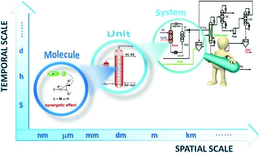 | ||
| Fig. 1 Schematic diagram of the multi-scale structure encountered in chemical engineering of IL technology for coupling CO2 with epoxides. | ||
2. Atom and molecule level: reaction mechanism
The general reaction mechanism of fixation of CO2 into cyclic carbonates involves nucleophilic attack by nucleophiles or electron-donating reagents at CO2, which conveniently produces carboxyl and carboxylate groups (Scheme 1).2 Further reactions of these species with electrophiles lead to the formation of organic carbonates. Therefore, increasing the basicity of oxides by transforming to oxy ions or the carboxyl carbon nucleophilicity of CO2 was usually used to facilitate the coupling of CO2 and epoxides.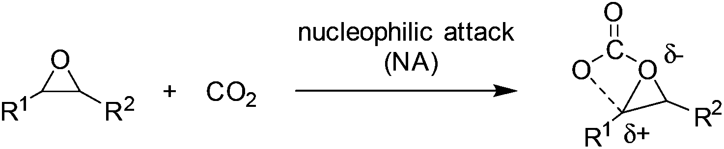 | ||
| Scheme 1 Nucleophilic attack at CO2 without IL mediation. | ||
Composed of distinct Lewis acidic cations and Lewis basic anions, ILs were regarded as more efficient catalysts potentially with the cooperative effect for the coupling of CO2 with epoxides. They could behave in various ways depending on the nature of either the cation or the anion. Here, the atom and molecular level will be discussed according to the catalytic mechanisms with which they operate and the parameters increasing the reaction activity and selectivity.
2.1 Ionic liquid (IL) single system
In the case of bulky and charge delocalized anions (e.g. BF4−, PF6−), the interaction between the epoxide and the anion is very weak and the anion rather interacts with CO2 to generate a new carboxyl anion species (see (1) in Scheme 2),22 which is more basic than the original anion, and thus able to attack the epoxide to generate a carbonate intermediate and finally the cyclic product. This pathway, although reported scarcely, was proposed on the basis of a mechanistic study by means of in situ ATR infrared spectroscopy.23 Alternatively, a nucleophilic attack on the epoxide by the anion of IL was expected to facilitate the opening of the C–O bond in epoxides, thereby producing oxy ion species (see (2) in Scheme 2).21 In addition, during the above CO2 activation or epoxide's ring-opening process, the structure of the cation also influences the behaviour of the anion in situ. That is, the bulky and delocalized cation will force itself away from the counter anion, and this less electrostatic interaction would make the anion more nucleophilic, while the less bulky and more nucleophilic cation, by binding the anion tightly, would decrease its availability for reaction with CO2 or epoxides.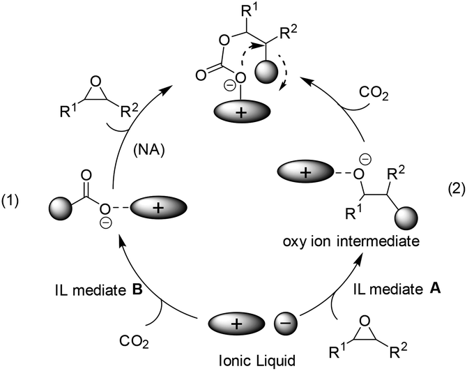 | ||
| Scheme 2 Nucleophilic attack at CO2 with IL mediation (1) nucleophilic attack at CO2 by the anion of IL directly; (2) nucleophilic attack at CO2 by oxy ions, the formation of which was facilitated by IL. | ||
The ILs used as catalysts for the coupling of CO2 with epoxides reported mainly follow path (2) in Scheme 2.24–37 Among them, the quaternary ammonium ILs, similar to one of the current catalysts in industrial operation, tetraethylammonium bromide (Et4NBr), are the most studied.38 Early in 1997, the synthesis of 5-membered cyclic carbonates from CO2 and epoxides, such as glycidyl methacrylate (GMA) and diglycidyl 1,2-cyclohexane dicarboxylate (DCD) in an organic solvent (e.g. toluene), was investigated by Park et al. in view of the characteristics of quaternary ammonium catalysts (named phase transfer catalyst at that time), reaction mechanism and kinetics.24 Among the salts tested, the one having a larger alkyl group and a more nucleophilic counter anion exhibited a better catalytic activity. Later, a straightforward method was discovered by simply dissolving the substrate in molten tetrabutylammonium bromide (TBAB) (120 °C) or tetrabutylammonium iodide (TBAI) (60 °C) in the presence of CO2 at atmospheric pressure.25 A plausible mechanism for this reaction would be the ring opening of the epoxide through a nucleophilic attack of the bromide ion, which can lead to an oxy anion species affording the corresponding cyclic carbonate after reaction with CO2. This methodology was further investigated in the coupling of butyl glycidyl ether (BGE) and CO2 in the presence of quaternary ammonium salt catalysts of different alkyl groups (C3, C4, C6 and C8) and anions (Cl−, Br− and I−).26 The catalytic activity increased with increasing alkyl chain length in the order of C3 < C4 < C6. However, the quaternary ammonium salt with a longer alkyl chain length (C8) decreased the conversion of BGE because it is too bulky to form an intermediate with BGE. For the counter anion of the tetrabutylammonium salt catalysts, the BGE conversion decreased in the order Cl− > Br− > I−, which was in contrast to the observation for the former phase transfer catalysts in the reaction of GMA or DCD with CO2.24
To better understand the reaction process and rationalize catalyst design for such systems in the future, Zhang et al. provided a detailed study on the related mechanism based on the general oxide substrates (EO and PO) from both experiments and DFT calculation (Scheme 3).27 In their work, the proposed three-step mechanism by Caló25 was recommended and further investigated by clarifying the optimized structures of the potential intermediates and the involved transition states. In addition, the effects resulted from the chain length of the cation or anion types in the quaternary ammonium salt were also analyzed. The pattern is in consistence with those found by Park26 although the oxide substrates used were different.
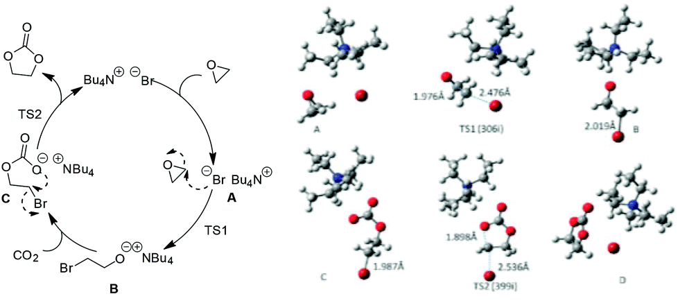 | ||
| Scheme 3 The proposed mechanism for fixation of CO2 with EO catalyzed by Bu4NBr (left); optimized geometries for the involved intermediates and transition states (right). Adapted from ref. 27. | ||
The anion–cation cooperative effect also works well in the case of using poly(ionic liquid)s (PILs) as the catalysts for coupling of CO2 with epoxides. In addition, the polymerized ILs have several positive characteristics as catalysts, such as enhanced stability, improved processability, and increased flexibility and durability. Han et al. first synthesized an active and insoluble PIL for the fixation of CO2 into cyclic carbonates, which was supported with 3-butyl-1-vinylimidazolium chloride on a highly cross-linked polymer matrix.37 Park et al. synthesized highly cross-linked porous poly(N-vinylimidazole-co-divinylbenzene) (PVIm) by suspension polymerization. The surfaces of the PVIm were then modified with various alkyl halides to obtain various IL-grafted porous polymer beads (PVIm-RX), which were then used as effective heterogeneous catalysts for fixation of CO2 with epoxides.14a
2.2 Ionic liquid (IL) binary system
The seeking for higher activity and efficiency stimulated continuous interest in the exploration of new catalysts for the conversion of CO2 to produce cyclic carbonates. In the light of the mechanism induced from the conventional IL catalysis system (the ionic liquid acts as the single catalyst component, see section 2.1), the idea in terms of catalysis development prevalently focused on finding a way to generate oxy ion species smoothly from oxides. Its essence is to enhance the cooperative effect caused by a catalyst/medium on the epoxide molecule, which will result in the ring-opening activation and the following coupling efficiency enhancement. To this end, both metallic Lewis acid and hydrogen bond donors (HBD) as additives/co-catalysts (Scheme 4C and 4D) were widely investigated, which resulted in a kind of bifunctional system in combination with ILs as the catalyst. Based on different co-catalyst types, the discussion here is divided into two categories: IL/metallic and IL/HBD binary systems.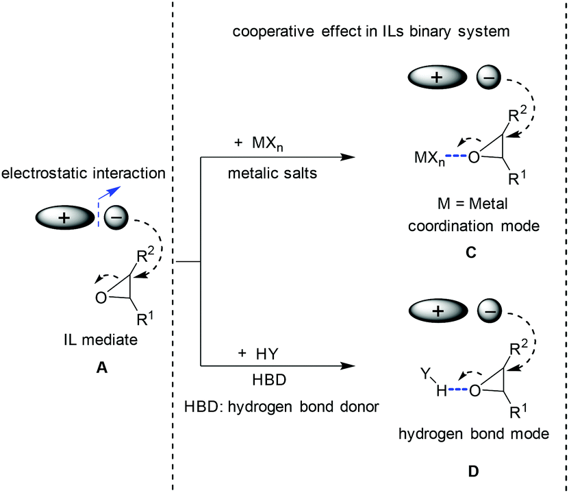 | ||
| Scheme 4 Different modes for the ring opening of epoxide. A: Cooperative effect induced by ion pairs; C: cooperative effect via coordination mode; D: cooperative effect via hydrogen bond mode. | ||
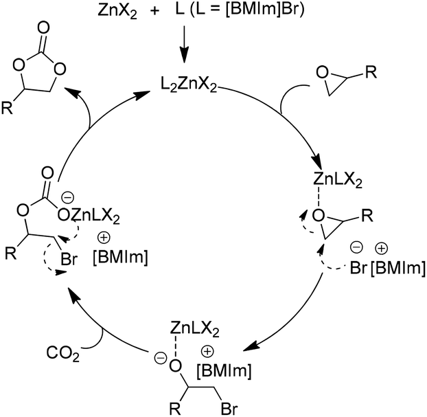 | ||
| Scheme 5 Catalytic cycle for ZnX2 facilitated addition of CO2 to epoxides in the presence of the [BMIm]Br. Adapted from ref. 41. | ||
| Entry | Epoxide | Catalyst | Conditions | Select. (%) | Yield (%) | Ref. (year) |
|---|---|---|---|---|---|---|
| 1 | EO | SalenAlCl/n-Bu4NBr | 120 °C, 15 MPa, 1 h | 99 | 61.4 | 39 (2002) |
| 2 | EO | (EMIm)2 ZnBr4 | 100 °C, 3.5 MPa, 1 h | 99 | 71.8 | 40 (2003) |
| 3 | SO | ZnBr2/[C4-mim]Cl | 80 °C, 4 MPa, 1 h | 99 | 93 | 42 (2004) |
| 4 | PO | SalenCo(III)X/n-Bu4NBr | 25 °C, 2 h | 99 | 49 | 43 (2004) |
| 5 | EO | [Dmim]2ZnBr2Cl2 | 100 °C, 3.5 MPa, 1 h | 99 | 98 | 46 (2004) |
| 6 | PO | ZnCl2/[BMIm]Br | 100 °C, 1.5 MPa, 1 h | 99 | 95 | 41 (2004) |
| 7 | PO | CS–ZnCl2/BMImBr | 110 °C, 15 MPa, 1 h | 99 | 95 | 44 (2005) |
| 8 | SO | Au/SiO2/ZnBr2/Bu4NBr | 80 °C, 1 MPa, 4 h | 25 | 21 | 45 (2005) |
| 9 | PO | [Bmim][InCl4] | 120 °C, 0.7 MPa, 1 h | 100 | 94 | 47 (2005) |
| 10 | SO | ZnBr2/n-Bu4NI | 80 °C, 8 MPa, 0.5 h | 99 | 92 | 48 (2005) |
| 11 | PO | ZnBr2/E | 100 °C, 4 MPa, 1 h | 99 | 94 | 49 (2006) |
| 12 | PO | ZnCl2/PPh3C6H13Br | 120 °C, 1.5 MPa, 1 h | 99 | 96 | 50 (2006) |
| 13 | EPO | Re(I) complex/IL | 80 °C, 1.5 MPa, 1 h | 99 | 98 | 52 (2007) |
| 14 | SO | SalenAlX/Bu4NBr | 25 °C, 0.1 MPa, 24 h | 99 | 98 | 62 (2007) |
| 15 | PO | ZnBr2/Ph4PI | 120 °C, 2.5 MPa, 1 h | 99 | 89 | 51 (2008) |
| 16 | Asymmetric PO | BINADCo(III)X/PTAT | 0 °C, 0.5 MPa, 72 h | 96 | 19.7 | 54 (2008) |
| 17 | PO | Zn3[Co(CN)6]2/nBu4NBr | 120 °C, 0.3 MPa, 6 h | 99 | 97 | 55 (2009) |
| 18 | EO | Sc[OTf]3/CTAB | 120 °C, 2 MPa, 4 h | 98 | 98 | 56 (2009) |
| 19 | PO | Zn4O(BDC)x(ABDC)3–x/NEt4Br | 140 °C, 3 h | 99 | 63 | 57 (2009) |
| 20 | PO | trans-RuCl2(py)4/CTAB | 80 °C, 3 MPa, 4 h | 99 | 98.6 | 58 (2010) |
| 21 | SO | [TBA]2ZnBr2Br2 | 80 °C, 5 MPa, 0.5 h | 99 | 94 | 53 (2010) |
| 22 | PO | MNP-P/PTAT | 25 °C, 1 MPa, 24 h | 99 | 97.9 | 59 (2011) |
| 23 | PO | ZnBr2/IL1 | 110 °C, 1.5 MPa, 1 h | 99 | 70.8 | 60 (2011) |
| 24 | SO | Zn(salphen)/Bu4NI | 45 °C, 8 MPa, 3 h | 99 | 96 | 61 (2012) |
| 25 | EO | [DMIm][Br2Zn(Me2PO4)2] | 120 °C, 3.5 MPa, 1 h | 99 | 79 | 64 (2012) |
| 26 | PO | ZnBr2/CH | 110 °C, 1.5 MPa, 1 h | 99 | 99 | 65 (2012) |
| 27 | SO | Cr-MIL-101/TBABr | 80 °C, 0.8 MPa, 14 h | 63 | 62 | 66 (2013) |
Up to now, a variety of metallic based compounds have been tested for this reaction,43–48 however zinc salts are still primarily used because of their comparative low cost and high efficiency. As another matched component, ILs have been expanded from dialkylimidazolium salts to hexabutylguanidinium,49 quaternary phosphonium,50,51 alkylpyridium,52,53 and quaternary ammonium39,54,55 based salts including TSILs, and various epoxides could be converted to the corresponding cyclic carbonates including those asymmetric substrates.43,53–62 Besides, the combination of the grafted ILs with a Lewis acid was also studied in searching for an enhanced effect. For example, FeCl3 was introduced into PS supported imidazolium chloride (MimCl), resulting in a new type of catalyst, PS supported MimFeCl4, which was then successfully used for the fixation of CO2 with epoxides.63
It is gradually accepted that the cooperative effect of IL and a metallic compound accounts for the high activity obtained by the IL/metallic binary system. During the catalytic process, ring opening of epoxide was considered as the rate-determining step. The metallic anion additionally facilitates an electrophilic interaction with the oxygen of the epoxide, while the counter anion of the ionic liquid (IL) facilitates a nucleophilic interaction with the β-carbon of the epoxide.
In the earlier stage, Zhang et al. reported that H2O could remarkably improve the activity of ILs and the corresponding reaction turnover frequency is about 4–5 times higher than that without water.67 Based on these experimental results, they proposed that an interaction between the H atom of the water molecule and the oxygen atom of epoxide through a hydrogen bonding might be an important factor for the activity improvement (Scheme 6).67 Thereafter, it has been demonstrated in the lab that HBDs, such as water,67 molecular sieves,68 chitosan,69 and phenol,70 can each act as co-catalysts to enhance the activity of ILs effectively for the cycloaddition. Additionally, the related DFT study, based on the 1,2-benzenediol–tetrabutyl ammonium bromide (TBAB) as the model catalyst, demonstrated that the activation and ring-opening of the epoxides via hydrogen bonding were the key steps towards making the catalytic process efficient.70 Actually, the HBDs facilitated catalytic coupling of CO2 and epoxides have been well investigated in terms of not only the IL systems but also alkali halide catalytic systems.71
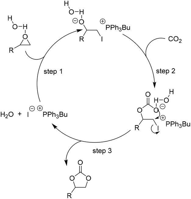 | ||
| Scheme 6 Catalytic cycle for H2O as HBD facilitated addition of CO2 to epoxides in the presence of [PPh3Bu]I. Adapted from ref. 67. | ||
Up to now, the HBD strategy has been employed to design task specific ILs (TSILs) by introducing a HBD functional group, i.e. hydroxyl,72 carboxyl,73–76 amine77,78 or amino acid,79–81 into IL backbones, which generated more efficient homogeneous catalysis systems taking advantage of the structurally tunable characteristic of IL molecules. Those TSIL active molecules can also be immobilized onto a solid support. Han et al. studied the supported choline chloride/urea as a heterogeneous catalyst using molecular sieves as a support.82 It was demonstrated that this biodegradable and green catalyst is very active and selective since choline chloride and urea showed a cooperative effect in promoting these reactions. The chlorine anion (combining with two urea molecules) of the IL opens the epoxy ring, which was activated by the choline cation through hydrogen bonding, to give the intermediate. Then, the intermediate further reacted with CO2 to form the corresponding cyclic carbonate and regenerate the catalyst. During this reaction process, the effect of urea could be attributed to its interaction with the chloride anion, which decreased the strength of the interaction between the chlorine anion and epoxides that led to higher selectivity. Similarly, a series of molecular sieve SBA-15 supported 1,2,4-triazolium-based ILs functionalized with the alkyl, hydroxyl or carboxyl acidic group were prepared and tested in the reaction of CO2 with various epoxides by Zhang et al.83 Upon catalytic property screen, catalysts with either –OH or –COOH functional groups exhibited excellent activity and selectivity, which is attributed to the inherent hydrogen bond donor property and thereof a cooperative effect with the halide anions upon interaction with epoxides for the ring opening. A carboxyl group was also introduced into the silica gel-grafted imidazolium-based ILs by Park et al.84 These heterogeneous catalysts show generally higher reactivity and selectivity compared with those without the –COOH group, and can be easily separated from the products and reused. Recently, organic polymer-supported hydroxyl functionalized ILs have drawn much attention, such as PS-supported hydroxyl-functionalized imidazolium ILs,85 PS-supported hydroxyl-functionalized diethanolamine ILs,86 PS-supported diol-functionalized imidazolium ILs87 and PS-supported choline chloride.88 The cooperative effect caused by the incorporated hydroxyl group as HBD and the anion species of ILs was supposed to be the main reason for the improved reaction activity. Yin et al. cleverly grafted the hydroxyl ILs onto the cross-linked divinylbenzene polymer (PDVB),17b which were observed having high activity for fixation of CO2 into cyclic carbonates without the use of any co-catalyst and organic solvent. Moreover, the newly prepared catalyst showed excellent stability and reusability, which was attractive for the industrial application. They also grafted carboxyl-functionalized imidazolium-based ILs onto PDVB and used them as the catalysts for this reaction under relatively mild reaction conditions.89
In some cases, the selected solid supports acted as HBD themselves during transformation. Among them, silica was one of the most studied materials for immobilizing catalysts both in academia and industry, which was also first introduced to construct immobilized ILs for fixation of CO2 with epoxides into cyclic carbonates (Table 2). In the study of a hybrid catalyst, Sakakura et al. demonstrated that phosphonium halides covalently bound to SiO2 exhibit excellent catalytic activities for synthesis of PC from PO and CO2.68 A plausible mechanism (Scheme 7) for improved activity accounted for the acidic surface silanol group interaction and activation of PO. The resulting more electrophilic carbon of PO is subsequently attacked by a nucleophile to open the ring. Nearly at the same time, He et al. studied the synthesis of cyclic carbonates from epoxides and CO2 using silica-supported quaternary ammonium salts as the catalyst under supercritical conditions. It was found that the supported catalysts were more active than the corresponding homogeneous ones in most of the tested cases.18a Thereafter, in the light of a similar reaction mechanism, many silica-supported ILs as catalysts for the coupling of CO2 with epoxides have been developed.90–98
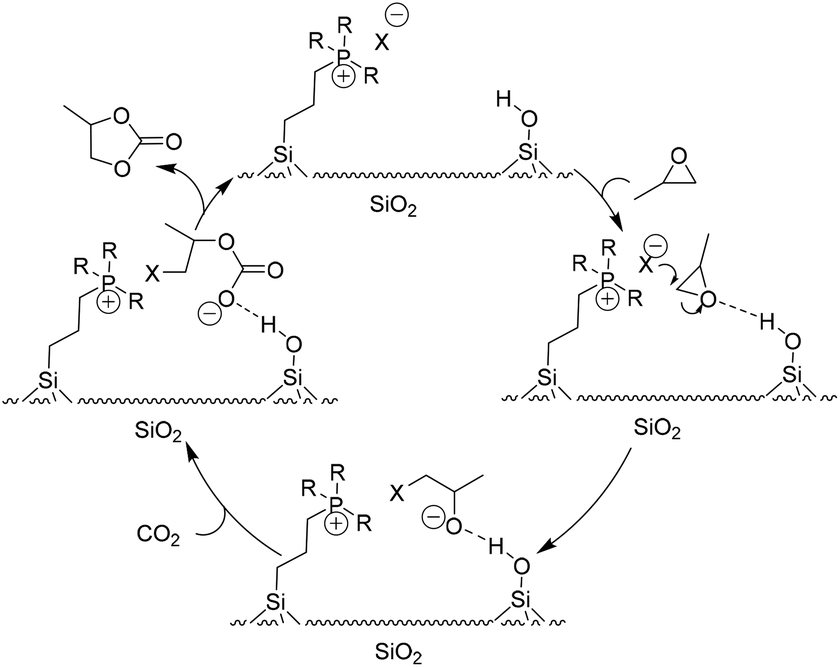 | ||
| Scheme 7 The proposed catalysis mechanism for the silica-supported IL catalytic system. Adapted from ref. 68. | ||
| Epoxide | Catalyst | Conditions | Select (%) | Yield (%) | Ref. (year) |
|---|---|---|---|---|---|
| PO | SiO2-(CH2)3-PBu3I | 100 °C, 10 MPa, 1 h | 100 | 100 | 68 (2006) |
| PO | SiO2-Bu4NBr | 160 °C, 8.0 MPa, 4 h | 99.0 | 96.0 | 18a (2006) |
| PO | SiO2-C4mimBF4 | 160 °C, 8.0 MPa, 4 h | 99.0 | 96.0 | 90 (2007) |
| PEAO | SiO2-BmimBr | 110 °C, 3.55 MPa, 6 h | 92.5 | 91.6 | 91 (2009) |
| PO | SiO2-(CH2)3-PBu3Br | 90 °C, 1 MPa, 6 h | >99 | 99.0 | 92 (2008) |
| PEAO | SiO2-IM-IL-imidazolium salt IL | 110 °C, 1.76 MPa, 6 h | 94.1 | 92.8 | 93 (2008) |
| SO | MCM-41-Imi/Br | 100 °C, 3 MPa, 4 h | 99.1 | 97.7 | 94 (2013) |
| PEAO | SiO2-imidazolium salt IL-Zn | 110 °C, 110psig, 3 h | 100 | 77.8 | 95 (2009) |
| PEAO | SiO2-imidazolium-based IL-Zn | 110 °C, 1.76 MPa, 6 h | 98.0 | 93.8 | 96 (2012) |
| PO | SiO2-CH/urea | 110 °C, 5 h | — | 99.0 | 82 (2007) |
| PO | SBA-15-hydroxyl-functionalized triazolium-IL | 110 °C, 2.0 MPa, 2 h | 99.0 | 99.0 | 83 (2013) |
| PEAO | SiO2-carboxyl acid-functionalized ILs | 110 °C, 1.62 MPa, 3 h | 99.0 | 98.0 | 84 (2011) |
| PO | SiO2-BmimBr | Microwave power = 200 W, 0.97 MPa, 15 min | — | 87.9 | 97 (2010) |
| PEPO | SBA-BimBr | 140 °C, 0.97 MPa, 15 min | 100 | 77.3 | 98 (2011) |
| PO | PEG NBu3Br | 120 °C, 4 MPa, 6 h | 98.0 | 99.0 | 99 (2006) |
| PO | PEG-PBu3Br | 120 °C, 1 MPa, 6 h | 99.0 | 99.0 | 100 (2007) |
| PO | PEG-TBDBr | 120 °C, 1 MPa, 3 h | 99.0 | 99.0 | 101 (2012) |
| PO | PEG-guanidium salt | 110 °C, 4 MPa, 4 h | 99.0 | 99.0 | 89 (2007) |
| PO | Ion exchange resin D201 | 120 °C, 8 MPa, 12 h | 97 | 99.0 | 16 (2005) |
| PEAO | MPR-HmimCl | 120 °C, 1.5 MPa, 4 h | 82.1 | 99.3 | 17c (2011) |
| PO | PS-HEIMBr | 120 °C, 2.5 MPa, 4 h | 97 | 99.0 | 85 (2009) |
| PO | PS-diethanolamine IL | 110 °C, 2 MPa, 2 h. | 99 | 100 | 86 (2012) |
| PO | PS-diol ILs | 125 °C, 2 MPa, 0.5 h. | 99 | 100 | 87 (2012) |
| PO | PS-choline chloride | 85 °C, 1 MPa, 6 h. | 98 | 99 | 88 (2013) |
| PO | PS-MimFeCl4 | 100 °C, 8 MPa, 6 h | 88 | 89 | 63 (2012) |
| PEPO | PDVB-hydroxyl ILs | 120 °C, 2 MPa, 4 h | 97.6 | 99.9 | 17b (2010) |
| PO | PDVB-carboxyl ILs | 120 °C, 2 MPa, 4 h | 96.1 | 99.8 | 105 (2012) |
| PO | CS-NMe3Cl | 160 °C, 4 MPa, 6 h | 98.0 | 98.0 | 102 (2007) |
| PO | CS-emimBr | 120 °C, 2.0 MPa, 4 h | 96 | >99 | 69 (2012) |
| PO | CMC-ILs | 110 °C, 1.8 MPa, 2 h | 98.6 | >99 | 103 (2012) |
| PO | PIL | 110 °C, 6 MPa, 7 h | 97.4 | — | 37 (2007) |
| PEAO | PVIm2-BuBr | 110 °C, 1.34 MPa, 6 h | 84 | >99 | 17a (2011) |
| PO | Hydroxyl-functionalized PIL | 120 °C, 2.0 MPa, 2 h | 76 | 100 | 70 (2012) |
| PO | Carboxyl-functionalized PIL | 120 °C, 2 MPa, 2 h | 95 | 100 | 104 (2013) |
Besides silica, an organic polymer, such as polyethylene glycol (PEG),89,99–101 and two of the most abundant natural biopolymers, chitosan (CS)69,102 and cellulose,103 as other excellent support materials, have been extensively studied, not only because of the potential combination of the unique properties of the organic polymer with the macromolecular architecture, but also because of the possibility of creating new properties and functions. He et al. prepared a series of heterogeneous catalysts by immobilization of quaternary ammonium salt,99 quaternary phosphonium salts,100 organic base (1,5,7-triazabicyclo[4.4.0]dec-5-ene) salts101 and guanidium salt89 onto PEG, which exhibit high activity in fixation of CO2 and epoxides into cyclic carbonates. One advantage of these PEG-grafted IL catalysts is that they can be homogeneously dissolved during the reaction and precipitate quantitatively in the separation stage, which makes catalyst recycling easy in addition to affording a high reactivity. Moreover, the enhanced efficiency could be partially attributed to the rich hydroxyl groups contained by PEG, that is PEG served not only as a support but also as a HBD type co-catalyst. The same group also developed CS-supported quaternary ammonium salts as catalysts to fix CO2 with epoxides into cyclic carbonates.102 Zhang et al. developed CS-functionalized ILs as recyclable biopolymer-supported catalysts for the same purpose.69 Park et al. also immobilized ILs on the carboxymethyl cellulose, which showed high catalytic activity and selectivity in the fixation of CO2 with epoxides under mild and solvent-free conditions.103
Meanwhile, Zhang et al. synthesized a series of hydroxyl-functionalized PILs as catalysts for the synthesis of cyclic carbonates from CO2 without the use of any co-catalyst or organic solvent.70,104 It was demonstrated that the hydroxyl group had an excellent cooperative effect together with the anionic parts of PILs on promoting the reaction.
2.3 Ionic liquid (IL) multifunctional system
Besides the above discussed IL single and binary systems, an IL multifunctional system was also explored to obtain a yield of the coupling reaction to its potential. For example, Zhang et al. externally employed metal halides as co-catalysts to the hydroxyl group functionalized ILs,65i.e. choline chloride (CH), to offer a typical case of the IL/HBD/metallic multifunctional system. Such a catalytic system was observed to be more efficient and biodegradable under an optimized condition. In the presence of CH alone or combined with Cu, Fe, Na, Al, K, and Mg chloride, the performance of the catalysis was unsatisfied; whereas in combination with zinc bromide, ZnBr2, it resulted in a greatly increased yield. The tentative mechanism, indicated by various cross experiments, was proposed and shown schematically in Scheme 8. The cooperative effect of ZnBr2 (via a coordination mode) and the hydroxyl group in CH (via hydrogen bond mode) on the oxygen unit of epoxides through a donor–acceptor bonding in general resulted in the polarization of C–O bonds. Meanwhile, the little bulky β-carbon atom of the epoxide was attacked by nucleophile Br−. The ring of the epoxide was therefore opened smoothly. Subsequent insertion to CO2 and intra-molecular substitution with bromide produced the cyclic carbonate and finished a catalytic cycle. From further experiment data, it showed that the reactivity also depends on the ratio of CH to ZnBr2 although each of them is necessary to the process. With an optimized ratio in 5![[thin space (1/6-em)]](https://www.rsc.org/images/entities/char_2009.gif) :1 (CH:ZnBr2), 99% yield of PC could be reached at 110 °C and 1.5 MPa of CO2 after reaction only for 1 h.
:1 (CH:ZnBr2), 99% yield of PC could be reached at 110 °C and 1.5 MPa of CO2 after reaction only for 1 h.
 | ||
| Scheme 8 Proposed mechanism for the coupling of epoxides with CO2 catalyzed by the combination of CH and ZnBr2. Adapted from ref. 65. | ||
Park et al., therefore, incorporated various metal chlorides (MCl2, M = Co, Ni, Cu, Zn and Mn) into silica-grafted imidazolium-based ILs with varied alkyl chain lengths bearing different anions (Cl−, Br−and I−) to produce a series of heterogeneous catalysts.95,96 Catalytic reaction tests demonstrated that the incorporation of such metal ions could significantly enhance the catalytic reactivity of the silica-grafted ILs towards cycloaddition reactions of CO2 and allyl glycidyl ether (AGE) that produce cyclic carbonates under solvent-free conditions.
3. Unit level: reactor configuration
Despite the above considerable developments made in the study on IL catalytic systems at the atom and molecular level, there was an obvious delay in the exploration of appropriate reactors at the unit level. Most of the reactions (the fixation of CO2 into cyclic carbonates) were still carried out in the batch reactors that were designed in response to the requirement for critical reaction conditions (e.g. high reaction temperatures, high pressures, and/or long time) by the traditional catalysis systems. Based on the well understanding of the reaction mechanism and properties of specific IL catalysts at the atom and molecule level, several research groups started to study the related continuous flow reaction at the unit level in order to offer detail information for new reactor designing. They did pioneering work, but still at the preliminary stage.IL catalysts described in the above section could also be categorized into two types, homogeneous and heterogeneous, in general. Zhang et al. made efforts on the reactor designing for both.106 In the case of homogeneous catalysts, they developed a bubbling bed process for synthesis of ethylene carbonate from ethylene oxide (EO) and CO2, as illustrated in Fig. 2.106a EO was initially pressurized with nitrogen to stay at the bed bottom as a liquid form, which was fed with ILs (5.6 wt% of EO), simultaneously. During this process, a CO2 gas stream (at twice the EO molar flow rate) was continuously injected and bubbled up through the liquid mixture of EO and ILs. Such a bubbling process promoted phase contact between the gas and the liquid, resulting in an efficient EO conversion, and more than 99.5% EO was converted. On the top of the bubbling bed reactor, a mixture of the EC product and the IL catalyst was collected and subsequently transferred to the next reactor, in which EC was hydrolyzed to ethyl glycol (EG). That is, the IL species used could act as a catalyst in both steps in the continuous EC–EG production, which makes the individual catalyst separation unnecessary and avoids energy consumption obviously.
 | ||
| Fig. 2 Bubbling bed process for ethylene carbonate synthesis and transformation. Adapted from ref. 106a. | ||
While in the case of heterogeneous catalysts, Zhang et al. employed a fixed bed reactor (Fig. 3),106b in which the catalyst, immobilized ILs, was filled in the bed in advance. Then, CO2 and EO were fed to the bottom of the reactor with a flow ratio of 2 to 1. The involved gas–liquid phases contacted and reacted at the surface of the pre-fixed catalyst. On the top of this reactor, only the EC product (nearly 99.5%) flowed out and was transferred to the next column for alcoholysis.
 | ||
| Fig. 3 Fixed bed process for ethylene carbonate synthesis and transformation. Adapted from ref. 106b. | ||
North et al. made an attempt for the synthesis of ethylene carbonate (EC) from “waste CO2” in a gas-phase continuous flow reactor (Fig. 4). In each reaction, a gas stream composed of 21% CO2 (total flow rate 4.7 mL min−1, in which 25% ethylene oxide and 54% N2) was used instead of pure CO2 and incorporated into a gas-phase flow reactor (length of 15 cm) filled with the supported bimetallic aluminium (salen) complex.107 As a result, the catalyst could convert up to 98% of the CO2 flowing through the reactor into EC. The result provides a chance for removing a significant percentage of the CO2 generated.
 | ||
| Fig. 4 Diagram of the gas-phase continuous flow reactor. Reproduced from ref. 107. | ||
Thereafter, in a gas-phase flow reactor, the same group carried out a further investigation on the impact of flue gas from the combustion of natural gas or coal in a combustion test facility on the activity of supported binary catalysts for the synthesis of cyclic carbonates from epoxides and waste CO2.108 In an example, a single batch of catalyst was divided into five samples each composed of 150 mg catalyst within a stainless steel tube (3 cm long × 1 cm diameter) fitted with screw fittings at each end to allow connection to the 20 cm diameter flue gas duct of the combustion test facility (Fig. 5). The components of flue gas were listed in Table 3 as reported by the author. In the batch reactions with styrene oxide as the substrate, some loss of catalyst activity was apparent and this was greater for the catalyst exposed to flue gas generated from burning coal than for the catalyst exposed to flue gas obtained by burning gas. In a gas-phase flow reactor with ethylene oxide as the substrate, the detrimental effect of flue gas exposure on the catalyst activity was much less apparent.
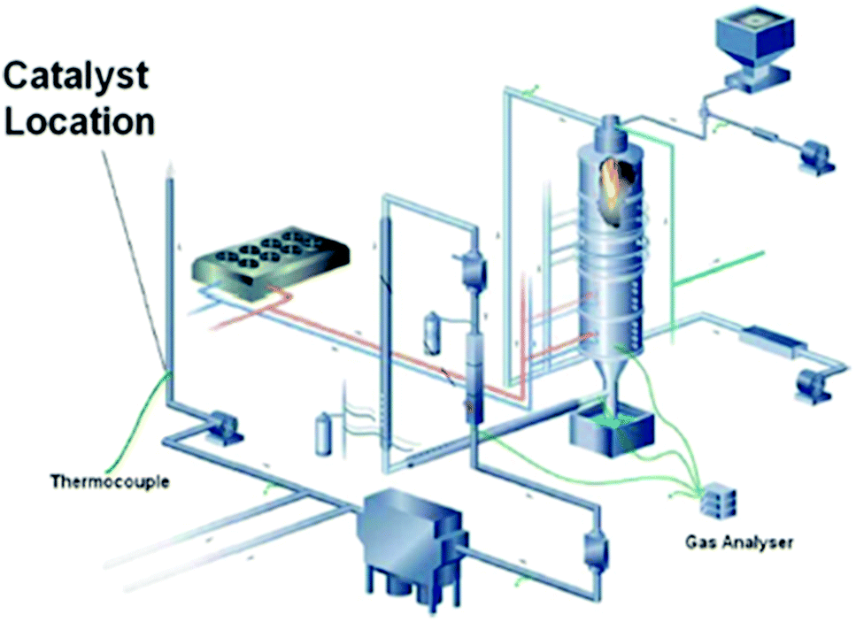 | ||
| Fig. 5 The DoosanBabcock combustion test facility used to expose the catalyst to flue gas. Reproduced from ref. 108. | ||
| Component | From gas combustion | From coal combustion |
|---|---|---|
| a The flue gas composition was measured using a Servomex 4900 continuous emission analyzer. | ||
| Temperature | 53.4 °C | 52 °C |
| CO2 (% v/v) | 5.1 | 15.12 |
| O2 (% v/v) | 8.7 | 3.4 |
| SO2 (ppmv) | 26.1 | 291.4 |
| CO (ppmv) | 189.3 | 39.9 |
| NOx (ppmv) | 33.3 | 443.0 |
Recently, Zhao et al. found that the synthesis rate of cyclic carbonate could be remarkably enhanced in a microreactor (Fig. 6).109 The catalyst used was hydroxyl-functionalized IL (HETBAB) and the residence time was dramatically reduced from several hours to about 10 s. The turnover frequency (TOF) value varies in the range of 3000 to 14000 h−1 compared to 60 h−1 in the conventional stirred reactor. The space time yield (STY) or the overall reaction rate ranges from 650 to 4500 gprod. (gcat. h)−1, which was much larger than the value in the conventional case [ca. 19 gprod. (gcat. h)−1]. However, even though the mass transfer performance of CO2 and PO can be improved in the microreactor, the reaction is still affected by gas–liquid mass transfer.
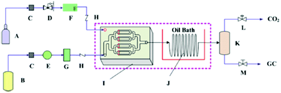 | ||
| Fig. 6 Schematic of the cycloaddition of PO and CO2 in a microreactor. A: CO2 cylinder; B: liquid tank (including PO and HETBAB); C: filter; D: pressure regulating valve; E: series II digital pump; F: gas mass flow controller; G: liquid damper; H: one-way valve; I: micromixer; J: spiral capillary in oil bath; K: gas–liquid separator; L: back pressure regulating valve; M: needle valve. Reproduced from ref. 109. | ||
As another efficient reactor, a microwave reactor was applied for the efficient synthesis of cyclic carbonate. For example, an environmentally-friendly synthesis of cyclic carbonates from CO2 and epoxides with a HCOOH/KI catalytic system was performed in a microwave reactor.110 The microwave power used in the reaction has a significant effect on the reaction rate, and 200 W of the microwave power could result in the best result (94% conversion with 93% yield). A further increase in the microwave power from 200 W to 500 W did not lead to significant enhancement in the conversion but brought about a slight decrease in the selectivity, which is possible because that higher temperatures attained with increasing microwave power suppress the dissolution of CO2, resulting in insufficient CO2 molecules available for cycloaddition to epoxides.
4. System level: process integration
Industrial applications of IL technology are nonlinear and complex processes involve multi-scale problems and cross-coupled factors. Efforts on the system integration and optimization of these processes are essential to maintain the critical balance among energy, economy and environment. In this section, the currently available industrial technologies in terms of the continuous transformation of CO2 to ethylglycol (EC) via cyclic carbonates were briefly introduced for an example case of system consideration. They were, in general, divided into two categories, hydrolysis and alcoholysis routes, with respect to the second transformation of cyclic carbonates to EC. Then, a system integration/optimization study on the alcoholysis line using the newly emerged IL technology was presented and discussed critically.4.1 Current industrial production technology
Among various cyclic carbonates, ethylene carbonate (EC) and propylene carbonate (PC) are the most used as important industrial organic carbonates and extensively investigated in terms of the techniques for their production using CO2 as the starting material to be implemented. Several companies have commercialized the production of EC or PC in the early stage; and some of the involved technologies are still used presently (Scheme 9). For example, Asahi Chemical developed a process for the production of EC by reacting ethylene oxide (EO) with CO2 in the presence of a pretreated strong basic anionic exchanger resin Dowex MSA1.111 The reaction was carried out at 100 °C with a CO2 pressure of 8.1 MPa. The conversion of EO was about 92% and the selectivity to EC was around 93%. Additionally, the remaining EO could be recycled. Lately, The Union Carbide and Scientific Design (UCSD) developed an EC production progress using KI or tetraethylammonium bromide as the catalyst,38 which was carried out at 190 °C and 3.5 MPa with a reaction time of 45 min. The EO conversion was 99% and the selectivity to EC was about 99.2%. The catalysts are separated by means of a falling film evaporator column sequence operating at about 50 mmHg. Meanwhile, Jefferson Chemical (now part of Texaco Chemical) developed a process catalyzed by a solution of 10–15% triethylamine and ethyl bromide in EC.112 The reaction was carried out at 155–195 °C and 10.34 MPa using an excess of 7 mol% CO2 and a catalyst concentration of 0.5% in EO. With the reaction time of 38 min in the reactor and 14 min in the flash drum, the EO conversion was 98% with 99% selectivity to EC. Besides, OMEGA developed a process catalyzed by tetrabutylphosphoniumiodide and K2CO3 dissolved in EG in the presence of H2O.38 The conversion of EO was higher than 99.9%.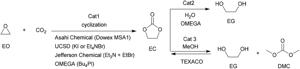 | ||
| Scheme 9 The available industrial techniques in the formation of EC and its downstream products. | ||
Along with the developments in techniques for commercialization of the EC and PC, exploration of their downstream products and progress in the synthetic technology of dimethyl carbonate (DMC) and glycols have attracted wide interest in both industry and academia. The representative ones are the OMEGA and TEXACO technologies. OMEGA technology produces ethylene glycol (EG) via EC from EO, CO2 and H2O (Scheme 9),112 while the TEXACO process produces both EG and DMC via EC from EO, CO2 and methanol (see Scheme 9).38
4.2 Process design for the IL technology
EC resulting from the coupling of EO with CO2 is generally regarded as the ‘vector’ for the ethylglycol (EG) considered as the third-massive product (after polyethylene and polyvinyl chloride in sequence) in industry. In the case of the esterification strategy, it is noteworthy to mention that ILs can be applied as catalysts not only in the initial cyclization but also in the sequential trans-esterification with methanol, therefore supplying a complete production line of EG through IL catalytic processes (Scheme 10).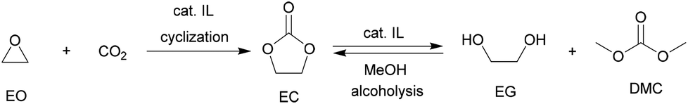 | ||
| Scheme 10 Alcoholysis line for EG production via EC under IL processes. | ||
In a study by Tian et al.,113 the IL catalytic processes for the coproduction of dimethyl carbonate (DMC) and ethyl glycol (EG) starting from EO and CO2 were integrated and optimized based on process simulation. It was found that the optimized IL process compared with the traditional Texaco process could increase the net profit per ton of EG by 11.5%, i.e. 593 RMB, and lower energy consumption by 8.7%. These results provided a theoretic guideline to the design of a real IL process.
4.3 Optimization of the process configuration for the IL technology
The modeling process flow sheet of EG/DMC production via IL catalysis is shown in Fig. 7. EO is pumped from the tank to the R101, and reacted with CO2 from the tank to produce EC. In sequence, the resulting EC and the remaining mixture of EO and a large excess of CO2 entered into the tube reactor R102 for further reaction. The resulting mixture from R102 was then sent to the flash tank V101. Here, the light component, CO2, from the top of the tank returned to R101 for recycling through the compressor K101. While the residue, a mixture of EC and the additional catalyst, was delivered into the top of reaction distillation tower (C201) for the countercurrent contacting with methanol from the bottom (MeOH:EC ≈ 8:1 (in molar ratio)). Of the resulting reaction mixture, the light components, MeOH, DMC and DME, standing at the top of the tower were delivered to C202 in order to facilitate subsequent removal of DME. After treatment, the bottom component was then sent into the distillation column C203 to generate pure DMC, which was sent to M202 for further purification. The DMC from the static mixer M202 was finally sent as a product. In contrast, heavy components, EG and entrained DMC, at the bottom of C201 entered into the EG/DMC separation column C204, which could offer the product EG in a purity of 99%.
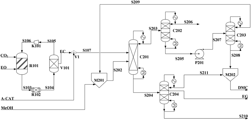 | ||
| Fig. 7 Flowsheet of DMC/EG co-production via the alcoholysis of EC. Adapted from ref. 113. | ||
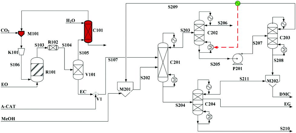
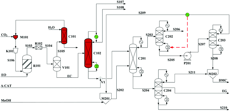
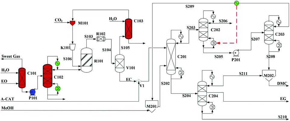
Built as an ideal case, the model described in Fig. 7, without taking into account sources of raw materials, heat integration, intermediate purification and other issues, is obviously not enough for a whole process design in terms of the optimal case and conditions thereof. In consideration of the industrial raw material EO containing some extent of water, which might induce hydrolysis of EC in the first cyclization reaction, three different scenarios were designed by Tian et al.113 based on the hydrolysis process of the EG set up by a petrochemical company in Beijing, China. They are as follows: EO containing 7%/w of water used as raw materials (I, Fig. 8), the process configuration including EC purification (II, Fig. 9), and the process configuration including EO purification (III, Fig. 10).
 | ||
| Fig. 8 Configuration I of the EG/DMC coproduction process. Adapted from ref. 113. | ||
 | ||
| Fig. 9 Configuration II of the EG/DMC coproduction process. Adapted from ref. 113. | ||
 | ||
| Fig. 10 Configuration III of the EG/DMC coproduction process. Adapted from ref. 113. | ||
In the process scheme of scenario (I) as shown in Fig. 8, the EO material with 7%/w water entered the esterification reactor (R101) and was mixed with CO2, which offered the main product EC and a small amount of by-products, EG and diethylglycol (DEG). After one step flash operation, the resulting reaction mixture was then directly transferred into the reactive distillation column (C201) for the alcoholysis with MeOH. In Fig. 8, the dashed arrow indicates the heat recovery of stream S209 from the top of C203, which was then used as a heat source for column C202.
In comparison, the process scheme of scenario (II) has an additional EC purification column C102 between two main reactors as shown in Fig. 9. The real product from the first-step reaction contains not only the expected ester EC but also its hydrolysis products, EG and DEG. In consideration of an equilibrium reaction characteristic of the second alcoholysis, the presence of EG and DEG in the feed material will decrease the conversion. And, with a lower conversion, it will be quite difficult for distillation of EG (197 °C/760 mmHg) from the unconverted EC (248 °C/760 mmHg). Therefore, it is expected reasonably to improve the efficiency of alcoholysis by supplying the purified EC from its mixture with EG and DEG.
In either scenario (I) or (II), the final EG purification column has only a limited distilling ratio with respect to the multi-components to be treated. The undesired products together with a part of EG, thus, have to be sent to the flare, which surely affects the entire EG yield. To avoid this unfavourable factor fundamentally, the potential side reactions have to be decreased. Note that the introduced crude EO contains a part of water (7% /w), the presence of which might affect the production line from two negative aspects: (1) it accounts for the hydrolysis of the intermediate EC to EG and, therefore, affects the balance of the subsequent alcoholysis to attain its potential conversion; (2) it facilitates the formation of side products during the coupling reaction, e.g. DEG and triethylglycol (TEG), which are difficult to be distilled off from the mixture. Therefore, pre-processing for removal of water from EO was added as explicated in Fig. 10.
EO, mixed with 7%/w of water, from the ethylene section entered the presented station (Fig. 10) and its purification was initiated going through the washing column C101. In column C101, the impurity gas was removed, while the aqueous material (90% EO) at the bottom was subsequently sent by the pump P1 to the upper section of the dehydration tower C102. After a multi-stage distillation, EO of 99% purity could be obtained at the top of C102, which was then sent to the esterification reactor. The remaining sections were the same as those of scenario (II).
In order to make a comparison between the above proposed scenarios, the energy distribution and total energy consumption of them were examined, respectively. As indicated in Fig. 11, the azeotropic distillation column and the reaction distillation column are the top two energy-consuming processes. Besides, either the EC purification column in scenario (II) or the EO dehydration column in scenario (III) accounts for a large proportion in the total energy consumption, respectively. Therefore, from the viewpoint of energy consumption, scenario (I) has an advantage over the other two.
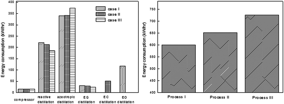 | ||
| Fig. 11 Energy consumption distribution (left) and total energy consumption (right) of the three configurations of the EG/DMC coproduction process. Adapted from ref. 113. | ||
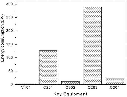
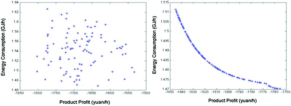
Besides the process configuration, operating conditions, such as energy consumption or yield, have a crucial influence on the process efficiency as well. After sensitivity analysis of the process configuration, which indicates that C201 and C203 are the main energy-consuming equipment as shown in Fig. 9, the multi-objective model was established in Tian's study113 based on the BP neural network114 by introducing a number of trays (NC201 and NC203) in the key column and the reflux ratio (RRC201 and RRC203) thereof as decision variables, and the purity of EC and DMC as constraint variables (PEC and PDMC), while the energy consumption and product benefit as the objective functions. In the end, the genetic algorithm NSGA II115 was applied to achieve a multi-objective optimization of the model. In such a binary-coded algorithm, each variable length code is 14, while the population size is 100, with a hereditary algebra of 100, a crossover probability of 0.8 and a mutation probability of 0.02. The resulting Pareto frontier solution set was then ranked by the TOPSIS method116 to obtain the optimal solution. Specific calculation results, as shown in Fig. 12 and 13, represent the distribution of the initial population and the population of 100 generations. It indicates that the 100 generation model converge well to the Pareto frontier.
 | ||
| Fig. 12 Distribution of energy consumption in the DMC/EG co-production process (capacity: 1000 tons of EG/year). Adapted from ref. 113. | ||
 | ||
| Fig. 13 Evolution of the optimal solution for the process at generation 1 (left) and the Pareto optimal solution set for the process at generation 100 (right). Adapted from ref. 113. | ||
In order to find the optimal process operating parameters, they used the TOPSIS decision method to sort the specific results, as shown in Table 4, where the first one is the optimal solution sort. Through optimization, it can be found that the tray numbers of C201 and C203 were reduced by 8 and 6 respectively, resulting in a reduced investment cost. Besides, 8.7% reduction in energy consumption and 0.9% increase in product revenue were obtained, thus increasing the energy efficiency significantly (Fig. 14).
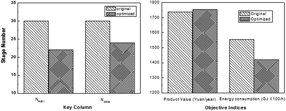 | ||
| Fig. 14 Stage numbers of key columns in the original process and the optimized process (left); performances of the original process and the optimized process (right). Adapted from ref. 113. | ||
| No. | N C201 | RRC201 | N C203 | RRC203 | Product income/RMB Yuan h−1 | Energy consumption/GJ h−1 |
|---|---|---|---|---|---|---|
| 1 | 22 | 0.260 | 24 | 1.6 | 1755.4 | 1.4703 |
| 2 | 22 | 0.263 | 24 | 1.6 | 1757.4 | 1.4703 |
| 3 | 22 | 0.265 | 24 | 1.6 | 1758.7 | 1.4704 |
| 4 | 22 | 0.267 | 24 | 1.6 | 1759.9 | 1.4706 |
| 5 | 22 | 0.270 | 24 | 1.6 | 1761.4 | 1.4708 |
5. Conclusions and perspectives
A lot of research studies on CO2 as C1 feedstock for production of value-added chemicals have been reported and received extensive attention both in academia and industry. In this context, from a multi-scale viewpoint, the research progress in the reaction of CO2 with epoxides to produce cyclic carbonates with respect to the newly emerged ILs is summarized and discussed.At the atom and molecule level, the cooperative effects were depicted in detail that offered a guideline for design and development of more efficient IL catalytic systems. However, the performance of ILs in the industrial applications, such as long term stability, toxicity, environmental impact, degradation and corrosion, should be addressed, the studies of which are still at the preliminary stage.117
At the unit level, several kinds of reactors such as the fixed bed reactor, bubble reactor, microwave reactor and microreactor for reaction of CO2 with epoxides have been discussed. However, the fundamental knowledge regarding the mass/heat transfer and their coupling effects with reactions has not yet been fully understood. It is also important to develop computational fluid dynamics (CFD) codes for the complex systems containing ILs.
At the system level, the current process integration in terms of the overall production stream stood at its initial stage. Optimization and assessment of the energy consumption and economic performance of the emerging technologies with ILs as catalysts or solvents will be a key step before their industrial commercialization.
Nevertheless, a multi-scale (molecule-unit-system) strategy is indispensably important for the commercialization of laboratory emerging technologies, therefore a parallel R&D mode, including IL design and synthesis, unit design, engineering scale up and process design, is accordingly required. Although there is a lot of work remaining to solve all of the scientific issues, we believe that a bright future is coming with the stimulation for lower energy consumption and lower cost CO2 utilization technologies worldwide under the pressure of greenhouse gas emission mitigation.
Acknowledgements
This work was supported by the National Natural Science Foundation of China (no. 21127011, 21036007, 21006117) and the fund of state key laboratory of Multiphase complex systems, IPE, CAS (no. MPCS-2012-A-01).Notes and references
-
(a) H.-Q. Yang, Z.-H. Xu, M.-H. Fan, R. Gupta, R. Slimane, A. E. Bland and I. Wright, J. Environ. Sci., 2008, 20, 14–27 CrossRef CAS
; (b) R. A. Khatri, S. S. C. Chuang, Y. Soong and M. Gray, Energy Fuels, 2006, 20, 1514–1520 CrossRef CAS
- Selected reviews for the CO2 transformation:
(a) M. Mikkelsen, M. Jørgensen and F. C. Krebs, Energy Environ. Sci., 2010, 3, 43–81 RSC
-
(a) P. Jessop, T. Ikariya and R. Noyori, Chem. Rev., 1995, 95, 259–272 CrossRef CAS
- Selected reviews for coupling of CO2 with epoxides:
(a) D. J. Darensbourg and M. W. Holtcamp, Coord. Chem. Rev., 1996, 153, 155–174 CrossRef CAS
- Selected reviews for polycarbonate formation:
(a) D. J. Darensbourg, Chem. Rev., 2007, 107, 2388–2410 CrossRef CAS PubMed
- Selected reviews for cyclic carbonate formation:
(a) A. Decortes, A. M. Castilla and A. W. Kleij, Angew. Chem., Int. Ed., 2010, 49, 9822–9837 CrossRef CAS PubMed
- Selected articles for urea formation from CO2:
(a) F. Shi, Y. Q. Deng, T. L. SiMa, J. J. Peng, Y. L. Gu and B. T. Qiao, Angew. Chem., Int. Ed., 2003, 42, 3257–3259 CrossRef CAS PubMed
-
(a) Z.-Z. Yang, L.-N. He, J. Gao, A.-H. Liu and B. Yu, Energy Environ. Sci., 2012, 5, 6602–6639 RSC
-
(a) A. J. Morris, G. J. Meyer and E. Fujita, Acc. Chem. Res., 2009, 42, 1983–1994 CrossRef CAS PubMed
- Selected reviews see:
(a) Y. Himeda, Eur. J. Inorg. Chem., 2007, 3927–3941 CrossRef CAS
-
(a) A.-A. G. Shaikh and S. Sivaram, Chem. Rev., 1996, 96, 951–976 CrossRef CAS PubMed
-
(a) N. Kihara, N. Hara and T. Endo, J. Org. Chem., 1993, 58, 6198–6202 CrossRef CAS
-
(a) T. Yano, H. Matsui, T. Kokie, H. Ishiguro, H. Fujihara, M. Yoshihara and T. Maeshima, Chem. Commun., 1997, 1129–1130 RSC
-
(a) W. N. Sit, S. M. Ng, K. Y. Kwong and C. P. Lau, J. Org. Chem., 2005, 70, 8583–8586 CrossRef CAS PubMed
-
(a) T. Aida and S. Inoue, J. Am. Chem. Soc., 1983, 105, 1304–1309 CrossRef CAS
- Y. Du, F. Cai, D. L. Kong and L. N. He, Green Chem., 2005, 7, 518–523 RSC
-
(a) L. Han, H. J. Choi, D. K. Kim, S. W. Park, B. Liu and D. W. Park, J. Mol. Catal. A: Chem., 2011, 338, 58–64 CAS
-
(a) J.-Q. Wang, D.-L. Kong, J.-Y. Chen, F. Cai and L.-N. He, J. Mol. Catal. A: Chem., 2006, 249, 143–148 CrossRef CAS PubMed
-
(a) H. Yasuda, L. N. He and T. Sakakura, J. Catal., 2002, 209, 547–550 CrossRef CAS
- F. Shi, Q. Zhang, Y. Ma, Y. He and Y. Deng, J. Am. Chem. Soc., 2005, 127, 4182–4183 CrossRef CAS PubMed
-
(a) J. Sun, S.-i. Dujita and M. Arai, J. Organomet. Chem., 2005, 690, 3490–3497 CrossRef CAS PubMed
- Selected reviews on the interaction between ILs with CO2:
(a) F. Jutz, J.-M. Andanson and A. Baiker, Chem. Rev., 2011, 111, 322–353 CrossRef CAS PubMed
- T. Seki, J.-D. Grunwaldt and A. Baiker, J. Phys. Chem. B, 2009, 113, 114–122 CrossRef CAS PubMed
- D. W. Park, J. Y. Moon, J. G. Yang and J. K. Lee, Energy Convers. Manage., 1997, 38, s449–s454 CrossRef CAS
- V. Caló, A. Nacci, A. Monopoli and A. Fanizzi, Org. Lett., 2002, 4, 2561–2563 CrossRef PubMed
- H.-Y. Ju, M.-D. Manju, K.-H. Kim, S.-W. Park and D.-W. Park, J. Ind. Eng. Chem., 2008, 14, 157–160 CrossRef CAS PubMed
- J.-Q. Wang, K. Dong, W.-G. Cheng, J. Sun and S.-J. Zhang, Catal. Sci. Technol., 2012, 2, 1480–1484 CAS
- J. Peng and Y. Quan, New J. Chem., 2001, 25, 639–641 RSC
- E.-H. Lee, J.-Y. Ahn, M. M. Dharman, D.-W. Park, S.-W. Park and I. Kim, Catal. Today, 2008, 131, 130–134 CrossRef CAS PubMed
- J.-I. Yu, H.-Y. Ju, K.-H. Kim and D.-W. Park, Korean J. Chem. Eng., 2010, 27, 446–451 CrossRef CAS PubMed
- H.-Y. Ju, J.-Y. Ahn, M.-D. Manju, K.-H. Kim and D.-W. Park, Korean J. Chem. Eng., 2008, 25, 471–473 CrossRef CAS
- H. Kawanami, A. Sasaki, K. Matsui and Y. Ikushima, Chem. Commun., 2003, 896–897 RSC
- N. V. Rees and R. G. Compton, Energy Environ. Sci., 2011, 4, 403–408 CAS
- H. Yang, Y. Gu, Y. Deng and F. Shi, Chem. Commun., 2002, 274–275 RSC
- Y. Wang, G.-Q. Yuan, Y.-C. Zeng and H.-F. Jiang, Chin. J. Org. Chem., 2007, 27, 1397–1400 CAS
- B. R. Buckley, A. P. Patel and K. G. U. Wijayantha, Chem. Commun., 2011, 47, 11888–11890 RSC
- Y. Xie, Z. F. Zhang, T. Jiang, J. L. He, B. X. Han, T. B. Wu and K. L. Ding, Angew. Chem., Int. Ed., 2007, 46, 7255–7258 CrossRef CAS PubMed
- S. H. Wang , PEP Rev., 92-1-1.
- X.-B. Lu, R. He and C.-X. Bai, J. Mol. Catal. A: Chem., 2002, 186, 1–11 CrossRef CAS
- H. S. Kim, J. J. Kim, H. Kim and H. G. Jang, J. Catal., 2003, 220, 44–46 CrossRef CAS
- F. Li, L. Xiao, C. Xia and B. Hu, Tetrahedron Lett., 2004, 45, 8307–8310 CrossRef CAS PubMed
- J. Sun, S.-i. Fujita, F. Zhao and M. Arai, Green Chem., 2004, 6, 613–616 RSC
- X.-B. Lu, B. Liang, Y.-J. Zhang, Y.-Z. Tian, Y.-M. Wang, C.-X. Bai, H. Wang and R. Zhang, J. Am. Chem. Soc., 2004, 126, 3732–3733 CrossRef CAS PubMed
- L.-F. Xiao, F.-W. Li and C.-G. Xia, Appl. Catal., A, 2005, 279, 125–129 CrossRef CAS PubMed
- J. Sun, S.-i. Fujita, F. Zhao, M. Hasegawa and M. Arai, J. Catal., 2005, 230, 398–405 CrossRef CAS PubMed
- J. Palgunadi, O. S. Kwon, H. Lee, J. Y. Bae, B. S. Ahn, N.-Y. Min and H. S. Kim, Catal. Today, 2004, 98, 511–514 CrossRef CAS PubMed
- Y. J. Kim and R. S. Varma, J. Org. Chem., 2005, 70, 7882–7891 CrossRef CAS PubMed
- J. Sun, S.-i. Fujita, F. Zhao and M. Arai, Appl. Catal., A, 2005, 287, 221–226 CrossRef CAS PubMed
- H. Xie, S. Li and S. Zhang, J. Mol. Catal. A: Chem., 2006, 250, 30–34 CrossRef CAS PubMed
- J. Sun, L. Wang, S. Zhang, Z. Li, X. Zhang, W. Dai and R. Mori, J. Mol. Catal. A: Chem., 2006, 256, 295–300 CrossRef CAS PubMed
- S.-S. Wu, X.-W. Zhang, W.-L. Dai, S.-F. Yin, W.-S. Li, Y.-Q. Ren and C.-T. Au, Appl. Catal., A, 2008, 341, 106–111 CrossRef CAS PubMed
- W.-L. Wong, K.-C. Cheung, P.-H. Chan, Z.-Y. Zhou, K.-H. Lee and K.-Y. Wong, Chem. Commun., 2007, 2175–2177 RSC
- S.-i. Fujita, M. Nishiura and M. Arai, Catal. Lett., 2010, 135, 263–268 CrossRef CAS
- L. Jin, Y. Huang, H. Jing, T. Chang and P. Yan, Tetrahedron: Asymmetry, 2008, 19, 1947–1953 CrossRef CAS PubMed
- M. M. Dharman, J.-I. Yu, J.-Y. Ahn and D.-W. Park, Green Chem., 2009, 11, 1754–1757 RSC
- A. Ion, V. Parvulescu, P. Jacobs and D. de Vos, Appl. Catal., A, 2009, 363, 40–44 CrossRef CAS PubMed
- W. Kleist, F. Jutz, M. Maciejewski and A. Baiker, Eur. J. Inorg. Chem., 2009, 24, 3552–3561 CrossRef
- Z. Bu, Z. Wang, L. Yang and S. Cao, Appl. Organomet. Chem., 2010, 24, 813–816 CrossRef CAS
- D. Bai, Q. Wang, Y. Song, B. Li and H. Jing, Catal. Commun., 2011, 12, 684–688 CrossRef CAS PubMed
- L. Xiao, D. Lv and W. Wu, Catal. Lett., 2011, 141, 1838–1844 CrossRef CAS
- M. Taherimehr, A. Decortes, S. M. Al-Amsyar, W. Lueangchaichaweng, C. J. Whiteoak, E. C. Escudero-Adan, A. W. Kleij and P. P. Pescarmona, Catal. Sci. Technol., 2012, 2, 2231–2237 CAS
- J. Meléndez, M. North and R. Pasquale, Eur. J. Inorg. Chem., 2007, 2007, 3323–3326 CrossRef
- J. Gao, Q.-W. Song, L.-N. He, C. Liu, Z.-Z. Yang, X. Han, X.-D. Li and Q.-C. Song, Tetrahedron, 2012, 68, 3835–3842 CrossRef CAS PubMed
- J. K. Lee, Y. J. Kim, Y.-S. Choi, H. Lee, J. S. Lee, J. Hong, E.-K. Jeong, H. S. Kim and M. Cheong, Appl. Catal., B, 2012, 111–112, 621–627 CrossRef CAS PubMed
- W. G. Cheng, Z. Z. Fu, J. Q. Wang, J. Sun and S. J. Zhang, Synth. Commun., 2012, 42, 2564–2573 CrossRef CAS
- O. V. Zalomaeva, N. V. Maksimchuk, A. M. Chibiryaev, K. A. Kovalenko, V. P. Fedin and B. S. Balzhinimaev, J. Energy Chem., 2013, 22, 130–135 CrossRef CAS
- J. Sun, J. Ren, S. Zhang and W. Cheng, Tetrahedron Lett., 2009, 50, 423–426 CrossRef CAS PubMed
- T. Takahashi, T. Watahiki, S. Kitazume, H. Yasuda and T. Sakakura, Chem. Commun., 2006, 1664–1666 RSC
- J. Sun, J. Wang, W. Cheng, J. Zhang, X. Li, S. Zhang and Y. She, Green Chem., 2012, 14, 654–660 RSC
- J.-Q. Wang, J. Sun, W.-G. Cheng, K. Dong, X.-P. Zhang and S.-J. Zhang, Phys. Chem. Chem. Phys., 2012, 14, 11021–11026 RSC
-
(a) J. Ma, J. Liu, Z. Zhang and B. Han, Green Chem., 2012, 14, 2410–2420 RSC
- J. Sun, S. Zhang, W. Cheng and J. Ren, Tetrahedron Lett., 2008, 49, 3588–3591 CrossRef CAS PubMed
- L. Han, S.-J. Choi, M.-S. Park, S.-M. Lee, Y.-J. Kim, M.-I. Kim, B. Liu and D.-W. Park, React. Kinet., Mech. Catal., 2012, 106, 25–35 CrossRef CAS
- J. Sun, L.-J. Han, W.-G. Cheng, J.-Q. Wang, X.-P. Zhang and S.-J. Zhang, ChemSusChem, 2011, 4, 502–507 CrossRef CAS PubMed
- Y. Zhou, S. Hu, X. Ma, S. Liang, T. Jiang and B. Han, J. Mol. Catal. A: Chem., 2008, 284, 52–57 CrossRef CAS PubMed
- J. Tharun, G. Mathai, R. Roshan, A. C. Kathalikkattil, K. Bomi and D.-W. Park, Phys. Chem. Chem. Phys., 2013, 15, 9029–9033 RSC
- N. Aoyagi, Y. Furusho and T. Endo, J. Polym. Sci., 2013, 51, 1230–1242 CrossRef CAS
- S. Foltran, J. Alsarraf, F. Robert, Y. Landais, E. Cloutet, H. Cramail and T. Tassaing, Catal. Sci. Technol., 2013, 3, 1046–1055 CAS
- K. Fukumoto, M. Yoshizawa and H. Ohno, J. Am. Chem. Soc., 2005, 127, 2398–2399 CrossRef CAS PubMed
- F. Wu, X.-Y. Dou, L.-N. He and C.-X. Miao, Lett. Org. Chem., 2010, 7, 73–78 CrossRef CAS
- Q. Gong, H. Luo, J. Cao, Y. Shang, H. Zhang, W. Wang and X. Zhou, Aust. J. Chem., 2012, 65, 381–386 CAS
- A. L. Zhu, T. Jiang, B. X. Han, J. C. Zhang, Y. Xie and X. M. Ma, Green Chem., 2007, 9, 169–172 RSC
- W.-G. Cheng, X. Chen, J. Sun, J.-Q. Wang and S.-J. Zhang, Catal. Today, 2013, 200, 117–124 CrossRef CAS PubMed
- L. Han, H.-J. Choi, S.-J. Choi, B. Liub and D.-W. Park, Green Chem., 2011, 13, 1023–1028 RSC
- J. Sun, W.-G. Cheng, W. Fan, Y.-H. Wang, Z.-Y. Meng and S.-J. Zhang, Catal. Today, 2009, 148, 361–367 CrossRef CAS PubMed
- X. Chen, J. Sun, J. Q. Wang and W. G. Cheng, Tetrahedron Lett., 2012, 53, 2684–2688 CrossRef CAS PubMed
- R. A. Watile, K. M. Deshmukh, K. P. Dhake and B. M. Bhanage, Catal. Sci. Technol., 2012, 2, 1051–1055 CAS
- A. J. R. Amaral, J. F. C. Coelho and A. C. Serra, Tetrahedron Lett., 2013, 54, 5518–5522 CrossRef CAS PubMed
- X.-Y. Dou, J.-Q. Wang, Y. Du, E. Wang and L.-N. He, Synlett, 2007, 3058–3062 CAS
- J. Q. Wang, X.-D. Yue, F. Cai and L.-N. He, Catal. Commun., 2007, 8, 167–172 CrossRef CAS PubMed
- H. Shim, S. Udayakumar, J. Yu, I. Kim and D.-W. Park, Catal. Today, 2009, 148, 350–354 CrossRef CAS PubMed
- T. Sakai, Y. Tsutsumi and T. Ema, Green Chem., 2008, 10, 337–341 RSC
- M.-K. Lee, H.-L. Shim, M. M. Dharman, K.-H. Kim, S.-W. Park and D.-W. Park, Korean J. Chem. Eng., 2008, 25, 1004–1007 CrossRef CAS PubMed
- J. N. Appaturi and F. Adam, Appl. Catal., B, 2013, 136–137, 150–159 CrossRef CAS PubMed
- L. Han, S.-W. Park and D.-W. Park, Energy Environ. Sci., 2009, 2, 1286–1292 CAS
- L. Han, M.-S. Park, S.-J. Choi, Y.-J. Kim, S.-M. Lee and D.-W. Park, Catal. Lett., 2012, 142, 259–266 CrossRef CAS
- M. M. Dharman, H.-J. Choi, S.-W. Park and D.-W. Park, Top. Catal., 2010, 53, 462–469 CrossRef
- M. M. Dharman, H.-J. Choi, D.-W. Kim and D.-W. Park, Catal. Today, 2011, 164, 544–547 CrossRef CAS PubMed
- Y. Du, J.-Q. Wang, J.-Y. Chen, F. Cai, J.-S. Tian, D.-L. Kong and L.-N. He, Tetrahedron Lett., 2006, 47, 1271–1275 CrossRef CAS PubMed
- J.-S. Tian, C.-X. Miao, J.-Q. Wang, F. Cai, Y. Du, Y. Zhao and L.-N. He, Green Chem., 2007, 9, 566–571 RSC
- Z.-Z. Yang, Y.-N. Zhao, L.-N. He, J. Gao and Z.-S. Yin, Green Chem., 2012, 14, 519–527 RSC
- Y. Zhao, J.-S. Tian, X.-H. Qi, Z.-N. Han, Y.-Y. Zhuang and L. N. He, J. Mol. Catal. A: Chem., 2007, 271, 284–289 CrossRef CAS PubMed
- K. R. Roshan, G. Mathai, J. Kim, J. Tharun, G. A. Park and D. W. Park, Green Chem., 2012, 14, 2933–2940 RSC
- T.-Y. Shi, J.-Q. Wang, J. Sun, M.-H. Wang, W.-G. Cheng and S.-J. Zhang, RSC Adv., 2013, 3, 3726–3732 RSC
- Y. Y. Zhang, S. F. Yin, S. L. Luo and C. T. Au, Ind. Eng. Chem. Res., 2012, 51, 3951–3957 CrossRef CAS
-
(a)
S.-J. Zhang, et al., Green Solvents and Energy Saving Process (in Chinese), Science Press, 2014, vol. 371–423, pp. 380–400, ISBN: 978-7-03-037961-0 Search PubMed
- M. North, P. Villuendas and C. Young, Chem. – Eur. J., 2009, 15, 11454–11457 CrossRef CAS PubMed
- M. North, B. Wang and C. Young, Energy Environ. Sci., 2011, 4, 4163–4170 CAS
- Y. Zhao, C. Yao, G. Chen and Q. Yuan, Green Chem., 2013, 15, 446–452 RSC
- J. Tharun, G. Mathai, A. C. Kathalikkattil, R. Roshan, J.-Y. Kwak and D.-W. Park, Green Chem., 2013, 15, 1673–1677 RSC
- Y. R. Chin , PEP Rev., 2011-6.
- R. H. Schwaar and E. Matsunaga, PEP rev., 83-3-3.
-
X. Tian, System integration of processes using ionic liquids: [D], Institute of Process Engineering Chinese Academy of Sciences (IPE), Beijing, 2011 Search PubMed
- S.-Y. Jiang, P. Li and K.-M. Xue, J. Cent. South Univ. Technol., 2004, 11, 27–30 CrossRef PubMed
-
M. Schoenauer, K. Deb, G. Rudolph, X. Yao, E. Lutton, J. Merelo, H.-P. Schwefel, S. Agrawal, A. Pratap and T. Meyarivan, A Fast Elitist Non-dominated Sorting Genetic Algorithm for Multi-objective Optimization: NSGA-II, in Parallel Problem Solving from Nature PPSN VI, Springer, Berlin/Heidelberg, 2000, vol. 1917, pp. 849–858 Search PubMed
- C.-T. Chen, Fuzzy Set. Syst., 2000, 114, 1–9 CrossRef
- Selected reviews on the environmental impact issue of ILs:
(a) M. Petkovic, K. R. Seddon, L. P. N. Rebelo and C. S. Pereira, Chem. Soc. Rev., 2011, 40, 1383–1403 RSC
| This journal is © The Royal Society of Chemistry 2015 |