Corrosion chemistry and protection of zinc & zinc alloys by polymer-containing materials for potential use in rechargeable aqueous batteries
Tuan K. A. Hoang
,
The Nam Long Doan
,
Kyung Eun Kate Sun
and
P. Chen
*
Department of Chemical Engineering and Waterloo Institute for Nanotechnology, University of Waterloo, 200 University Avenue West, Waterloo, Canada. E-mail: p4chen@uwaterloo.ca; Fax: +1-519-888-4347; Tel: +1-519-888-4567 ext. 35586
First published on 29th April 2015
Abstract
The use of zinc and its alloys in rechargeable aqueous batteries faces a major problem: corrosion. This must be overcome to ensure the delivery of the sustainable hybrid rechargeable aqueous battery system. In this review, the mechanism of zinc corrosion in acidic aqueous electrolytes has been discussed, followed by a summary of corrosion studying methods. The use of polymer-containing materials to protect zinc from corrosion and their possible applications in batteries are also discussed.
1. Introduction
Corrosion of zinc (Zn) and zinc alloys has long been a fundamental and technical issue associated with the use of Zn in various industrial applications, from the use of Zn as negative electrode in Zn–carbon primary batteries to anti-corrosion coating layers on steel.1–3 Recently, many papers have been published addressing the use of Zn foil as anode in hybrid rechargeable aqueous batteries (ReHABs).4–7 These systems consist of a lithium intercalation compound as the cathode, an aqueous solution containing a mixture of Li+ and Zn2+ cations as the electrolyte, and zinc metal foil as the anode.4 The functioning mechanism of ReHAB is represented in Fig. 1.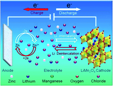 | ||
| Fig. 1 Schematic representation of the proposed mechanism for rechargeable hybrid aqueous battery operation. Reprinted with permission from ref. 4. Copyright 2012, Elsevier. | ||
When charging, Li+ is de-intercalated from the cathode and Zn2+ is deposited onto the surface of the Zn anode. Reversely, Li+ is intercalated to the cathode lattice from the aqueous medium, and Zn2+ is dissolved in the aqueous medium when discharging. In the current system,4 LiMn2O4 is the limited reagent because Zn is used excessively. LiMn2O4 loading can be varied depends on the applications while Zn surface area can not be changed in case Zn foil is used. The quantity of Zn in a battery depends on the contact surface area with a separator and the thickness of Zn foil, which, in turn, depends on the commercial availability. In general, it is preferred to use the Zn foil as thin as possible to enhance energy densities of the batteries. Furthermore, the existence of side reactions, such as the corrosion of Zn anode, can cause unwanted Zn consumption and affect the performance of batteries.
To further understand the electrochemistry occurring on the Zn surface, it is necessary to study Pourbaix diagrams of Zn in aqueous media. Fig. 2 is the Pourbaix diagram of Zn in aqueous environment considering ZnO as the solid product and Zn2+ existing in the electrolyte. At pH > 4.0, high overpotential limits H2 evolution, which becomes significantly more problematic at lower pH values.8
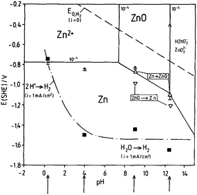 | ||
| Fig. 2 Pourbaix diagram of the system Zn/H2O, 10−4 M Zn2+ considering ZnO as solid substance, (↑) ≡ Ecorr (t = 1–24 h) (Δ,∇) ≡ oxidation/reduction peaks, (■) Ei,H2 (1 mA cm−2). Reprinted with permission from ref. 8. Copyright 1991, Elsevier. | ||
On the Pourbaix diagram, the equilibrium H2 evolution line (dotted line) is well above the equilibrium Zn dissolution (and deposition) lines. However, pure Zn has high hydrogen overpotential, and hydrogen evolution is only important in strongly acid solutions. When pH is higher and the electrolyte environment becomes alkaline, oxygen reduction is the dominating cathodic corrosion reaction.8 The potential of hydrogen evolution referring to a current density of iH2 = −1 mA cm−2 is indicated by the black squares. Compared with the equilibrium potential of the hydrogen electrode and its dependence on pH, a high cathodic overpotential for the hydrogen evolution reaction at the Zn electrode in the range of −1.3 V (pH = 4) to −0.8 V (pH = 0.4) is found.8
Up to date, improvements mainly focus on cathode materials. It has been shown that doping LiMn2O4 may provide higher stability4 and nanoscale materials contribute to higher rate capability of the batteries.5 However, methods are yet to be found to improve the stability of Zn anode as well as minimizing the side reactions occurring in the working or offline batteries.9
If corrosion on the Zn anode surface can be mitigated, crucial improvements on the ReHAB can be made. First, decreasing the quantities of Zn metal foil leads to lower cost. Second, cyclability can be improved. Third, the system will be even more sustainable comparing with current examples.4–7
Fig. 3a represents a simple scheme of zinc containing materials as an anti-corrosion layer on steel, where zinc is a sacrificed agent to protect the underneath steel from environmental attacks. In this case, anti-corrosion studies characterize the interfacial phenomena between the zinc coating and the environment. A typical simple stacking structure of the ReHABs and related systems is represented in Fig. 3b, where interfacial chemistries between the zinc containing anode and the electrolyte environment play an important role. Thus, to improve the performance of the batteries, fully understanding and controlling the interface between the zinc containing anode and the electrolyte is one of the fundamental keys. Knowledge in the anti-corrosion studies could definitely be appropriately exploited and applied in this aqueous energy storage system. Moreover, this may be related to other power sources employing zinc as an electrode.
This work introduces the literature review of corrosion of zinc and zinc alloys in the view from aqueous battery research. We will briefly introduce (i) the corrosion of zinc in acidic environments containing common anions (sulphate, chloride, acetate, nitrate), (ii) methods to study corrosion since – to the best of our knowledge – there is not any intensive review on the corrosion study methods focusing on zinc and zinc alloys. The last part (iii) focuses on the application of polymer-containing materials in corrosion inhibition for zinc and zinc alloys with possible uses in aqueous batteries and related systems.10 These methods and materials are currently applied in our laboratories.
2. Corrosion mechanism in acidic aqueous electrolytes
In acidic aqueous electrolyte without the presence of complexation agent, Zn dissolution contains two steps:11–14| Zn – 1e− → Zn+ | (a) |
| Zn+ – 1e− → Zn2+ | (b) |
The rate determining step is (b). Zn+1 is not stable and there is no such compound reported in the literature. Standard electrochemical potential of Zn/Zn2+ is −0.763 V vs. SHE. In aqueous environment, Zn2+ ion is hydrated. There are 10–12H2O molecules around each Zn2+ cation, and the dynamic radius of the whole system is 0.74–0.83 nm.15
In the case where Zn metal is in contact with acidic electrolyte containing Zn2+ as the only soluble form, the equilibrium is written as:
| Zn(solid) = Zn2+ + 2e− | (c) |
Standard potential:
The equilibrium equation and the standard potential are different if Zn is in contact with alkaline media, and other Zn-containing species are the corrosion products. The common compounds found in the corrosion products are zinc sulphate, zinc sulphate hydrate, zinc sulphate hydroxide hydrate, zinc chloride, and zinc carbonate (at neutral pH). In an aqueous medium, corrosion potential increases with the Zn2+ concentration.8 The addition of Zn2+ to the electrolyte reduces the corrosion current on the Zn electrode because Zn2+ cations act as cathodic inhibitor.16 There may be Zn(OH)2 created on the Zn surface at a locally high pH area.
The zinc will remain as bare surface when in contact with sodium chloride or sodium sulphate electrolyte with pH < 3.8. When pH becomes higher than 5.8, ZnO is created on the surface of Zn.11
Eqn (c) represents the anodic reaction, where Zn is losing its electrons, protons at the vicinity near Zn surface may react with these electrons and deliver hydrogen gas, which is the cathodic reaction. As a consequence, Zn2+ concentration increases and the electrolyte becomes less acidic. If pH of the electrolyte goes over 5.8, there is a change in corrosion mechanism because the formation of ZnO must be taken into account. The corrosion rate of Zn metal immersed in distilled water is about 45–48 μm per year.17–19 This rate is reduced if there is phosphate or nitrate present in the solution.17,18 Phosphate anion creates a non-soluble layer of zinc phosphate on the zinc surface while nitrate oxidizes zinc surface to create a layer of zinc oxide, leading to passivation of the zinc surface. Addition of sodium or potassium sulphate in electrolyte results in higher corrosion rates. The concentrations of these salts seem to be proportional with corrosion rates. For example, 0.1 N Na2SO4 solution delivers a corrosion rate of 70 μm per year on Zn electrode while 5 g L−1 Na2SO4 (or 0.035 M) solution delivers 65 μm per year. At the same concentration of 5 g L−1, Zn corrodes more severely in NaCl solution (90 μm per year) than that in Na2SO4. De-aeration of electrolyte may decrease the corrosion rate.18
In the batteries using Zn as the anode, most of the corrosion happens during discharge process, where Zn atom gives away its two electrons and dissolves into the liquid phase in the form of soluble Zn2+ cation. During the charge process, the reverse reaction occurs, leading to the cathodic protection on Zn; thus, the corrosion in this step may be self-minimized.
3. Methods to study corrosion
3.1 Electrochemistry methods
This method was used in the evaluation of the corrosion protection of steel by zinc and zinc–manganese alloy coating.21 Zn and Zn–Mg alloy deposition on steel 4130 substrate were prepared at room temperature using an acidic chloride electrolyte (pH = 4.00), consisting of zinc chloride, manganese chloride, sodium gluconate, potassium chloride, and boric acid. Corrosion studies were conducted using a three electrode setup with 3.5 wt% NaCl aqueous electrolyte. The variation of Ecorr over time for Zn–Mn and Zn is shown in Fig. 4. It is observed that the bare Zn deposit reached steel potential after 40 h while the potential of Zn–Mn alloy (17% Mn) deposit gradually increased and reached the steel potential only after 30 days. The result confirms that the Zn–Mn alloy is more resistant to corrosion than the bare Zn coating.
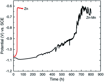 | ||
| Fig. 4 Ecorr vs. time curve for Zn and Zn–Mn alloy. Reprinted with permission from ref. 21. Copyright 2014, Elsevier. | ||
Fig. 5 shows an example of employing linear polarization to analyse the passivation behaviour of a Zn–Mn alloy coating on steel. A Tafel fit was conducted and the Icorr value shows that the corrosion current on Zn–Mn alloy deposits is an order of magnitude smaller than that of the bare Zn deposits.21
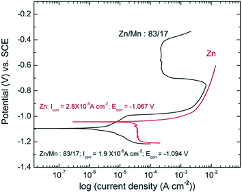 | ||
| Fig. 5 Passivation behavior of Zn–Mn alloy coating. Reprinted with permission from ref. 21. Copyright 2014, Elsevier. | ||
The monitoring of Rp (or Ecorr, Icorr) over time is called corrosimetry. By repeating the linear polarization around the corrosion potential at fixed time intervals, Rp can be calculated and plotted versus the monitoring time. The monitoring time could be a few hours up to several months. Millet et al. studied the corrosion behaviour of zinc–nickel alloy coating electro-deposited on steel.23 In this study, evolution of polarization with the duration of immersion of Zn–Ni alloys in a neutral saline environment were investigated. The solution was prepared with 30 g L−1 NaCl concentration, buffered by a mixture of 1.25 g L−1 H3BO3 and 0.19 g L−1 Na2HPO4 (pH = 6.5–7.0) (Fig. 6).
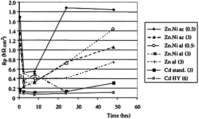 | ||
| Fig. 6 Evolution of the polarization resistance with the duration of the immersion; coatings without chromate passivation, Zn–Ni prepared in an acidic (ac) or alkaline (al) bath + Zn and Cd (standard or high yield) coatings, given for comparison at different current densities (figure given in parentheses). Reprinted with permission from ref. 23. Copyright 2000, Elsevier. | ||
For a short immersion (<1 h), the polarization resistance increases where the nickel content in the deposit is greater. For the ‘acidic’ and ‘alkaline’ coatings at 3 A dm−2, the polarization resistance decreases sharply at the beginning of the immersion, then this decrease is reduced – meaning that the corrosion rate slow down, probably due to the formation of the barrier layer by the resulting products. The ‘alkaline’ coating at 0.5 A dm−2 the one for which the Rp variation is the weakest over time. After 48 h of immersion, the most resistant coating is that of the 0.5 A dm−2 ‘acidic’ deposit.
For zinc and cadmium deposits, on the other hand, the polarization resistance does not change significantly over time.
An alternative of the LP method is the generalized corrosion technique (GC), or namely the uniform corrosion study because GC is installed in some electrochemical workstations to specifically study corrosion, which is more or less uniformly distributed over the entire exposed surface of a metal. The information obtained from GC is similar to those obtained from the LP.
Yao et al. studied the corrosion behaviour of magnetron sputtered Zn–Mg coating deposited onto electro-galvanized steel by various techniques including EIS.24 The anticorrosion property of Zn coating is enhanced significantly by the Zn–Mg layer. The ESEM images, the open circuit potential–time curves, and EIS results reveal a growing process of the formation of a passive film on Zn–Mg coating during saltwater immersion test. The EIS data and the fitting equivalent circuit are presented in Fig. 7 and Table 1.24 Significantly improved corrosion resistance of Zn–Mg coating layer can be attributed to the formation of the uniform layer of Mg modified Zn5(OH)8Cl2·H2O compound. During the corrosion process, less noble Mg reacts preferentially and a layer of magnesium hydroxyl carbonate forms on the coating surface, which is electrochemically inert.
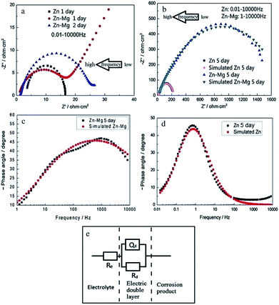 | ||
| Fig. 7 EIS diagrams of Zn and Zn–Mg coatings with different immersion times in 3.5% NaCl solution: (a and b) Nyquist diagrams, the arrows indicate the direction of increasing frequency; (c and d) Bode phase angle diagrams. (e) The fitting equivalent circuit of EIS diagrams for modelling impedance parameters for Zn and Zn–Mg coatings, which were immersed in 3.5 wt% NaCl solution for 5 days: Re is the electrolyte resistance (ohm cm2); Rd is the charge-transfer resistance (ohm cm2); Qd is a constant phase angle element (CPE) which presents the double layer capacitance. Reprinted with permission from ref. 24. Copyright 2014, Elsevier. | ||
| Symbol | Re (Ω cm2) | CPE, Yo (S sn cm−2) | n | Rd (Ω cm2) |
|---|---|---|---|---|
| a Re is the electrolyte resistance (Ω cm2); Rd is the charge-transfer resistance (Ω cm2); Qd is a constant phase angle element (CPE) which represents the double layer capacitance; Yo is the initial admittance of constant phase angle element (CPE); n is the dispersion coefficient, which is a dimensionless parameter in the range of 0–1. | ||||
| Zn coating | 19.25 | 0.004753 | 0.8 | 212.6 |
| % Error | 0.8685 | 2.187 | 1.146 | 2.043 |
| Zn–Mg coat | 11.24 | 5.8 × 10⁻⁵ | 0.5853 | 1808 |
| % Error | 5.188 | 3.721 | 0.8888 | 2.052 |
K. Darowicki proposed and demonstrated this method on studying corrosion of carbon steel in aqueous solution containing 0.5 M (H, Na)2SO4 with pH = 0.78 by non-linear EIS. The Icorr data are of high agreement with the data obtained from linear polarization method. There are different opinions about applying this method to study corrosion.25,26 Diard et al. later suggested that this method is only valid for low amplitudes of the perturbation signal, neglecting the influence of the ohmic drop. Moreover, if the electrolyte resistance is non-negligible and no IR compensation is carried out experimentally, this theoretical expression is incorrect.26 By a quick response, Darowicki re-established the non-linear EIS method.27 The effective perturbation signal depends on the resistance of the electrolyte, the polarisation resistance determined for a given amplitude of the generated perturbation signal and the amplitude of the generated perturbation signal. The analysis of impedance spectra leads to determination of effective amplitudes of the perturbation signal and the corresponding polarisation resistance values.
Recently, non-linear effects were introduced by excitations or perturbations. From this method, the impedance, the level of the disturbing noise, the level of non-linear distortions, and the level of the non-stationary behaviour are simultaneously measured during a single experiment.28 The method is used to determine pitting corrosion on aluminium29 and the onset corrosion of coated steel.30 Darowicki and co author proposed a similar type of applying non-linear perturbations through the so-called exponential chirp signal.31
Macias studied corrosion of zinc-coated reinforcements in simulated concrete pore solutions by harmonic analysis measurements and compare the results to those obtained from linear polarization and electrochemical impedance spectroscopy.35 Moreover, the values of corrosion intensity obtained from these techniques were compared with those obtained gravimetrically. In the beginning of the experiments, both LP results and harmonic analysis results are approximated (Icorr of 101 to 102 μA cm−2). When increasing experimental time, larger fluctuations in Icorr were observed in harmonic analysis measurements. The method is improved, and recent reports show better agreements with LP and gravimetric methods (<10% deviation).36 Harmonic analysis of carbon dioxide corrosion of mild steel under a variety of conditions have been reported.37 In this study, the corrosion current determined by harmonic analysis is more accurate than the results from linear polarization.
Amin et al. studied the metastable and stable pitting events at zinc passive layers in alkaline solutions. Half-cycle potentiodynamic anodic polarization curves were recorded for Zn in 0.5 M NaOH solutions, without and with ClO4− or ClO3− anions (concentrations 0.01–0.10 M), and with different starting cathodic potentials Es,c at 25 °C. In all cases, there is a well-defined anodic peak A1, occurring at the corrosion potential Ecorr, related to the formation of a Zn(OH)2 barrier layer. That peak is followed by a wide passive region which extends up to the rise of the second anodic peak (shoulder) A2, which is assigned to the formation of the passive ZnO2 film. Oxygen evolution explains the subsequent current increase as the potential is continuously increasing (Fig. 8).
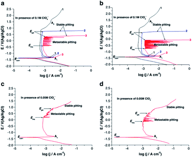 | ||
| Fig. 8 Potentiodynamic anodic polarization curves recorded for Zn in 0.5 M NaOH solutions without (curves1) and with (curves 2 and 3) ClO4− or ClO3− anions of different concentrations (0.05 and 0.1 M) at a scan rate of 10−4 V s−1 at 25 °C. Curves1 and 3 were swept starting from a cathodic potential of Es,c = −2 V. Curves 2 were started from the respective corrosion potential. Reprinted with permission from ref. 38. Copyright 2014, Springer. | ||
In this work, chronoamperometry technique was applied in conjunction with potentodynamic polarization, and the current spikes responsible for pitting were observed after a specific incubation time.38
Amin et al. studied pitting corrosion of zinc in alkaline medium containing thiocyanate anions. The potentodynamic polarization of Zn electrode in 0.50 M KOH containing 0.08 M KSCN was studied at different temperatures from 5 to 55 °C.39 The first peak in the range of −1.5 to −1.2 V corresponds to the electro-formation of Zn(OH)2 and the area between this peak and the rising tail is called the passive region. An increase in temperature enhances jp (current density at the first peak) and shifts the certain breakdown potential Ep (potential at the end of passive region and beginning of rising tail) towards more negative values (Fig. 9). Moreover, a rise in temperature increases jpass (current in passive region) and shifts Eb towards more negative direction, corresponding to an increased susceptibility to pitting. The relation between Eb and temperature is given in Fig. 10. An increase in temperature accelerates the rates of diffusion and migration of the reactant and product species, – thus, the corrosion reactions increases.
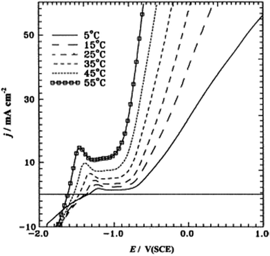 | ||
| Fig. 9 Potentiodynamic anodic polarization curves recorded for a Zn electrode in 0.50 M KOH + 0.08 M KSCN solution at a scan rate of 5 mV s−1 and at different temperatures. Reprinted with permission from ref. 39. Copyright 2003, Elsevier. | ||
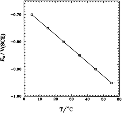 | ||
| Fig. 10 Dependence of the breakdown potential (Eb) on temperature for a Zn electrode in 0.50 M KOH + 0.20 M KSCN solution. Reprinted with permission from ref. 39. Copyright 2003, Elsevier. | ||
Moayed et al. studied corrosion behaviour of stainless steel by a combination of several electrochemical techniques. Critical pitting temperature was determined by applying a constant anodic potential and the temperature was gradually increased. The current was monitored continuously and a sudden rise (pitting) of current was detected at a certain critical temperature.40
When studying more than one electrodes together in the electrochemical cell, the technique is named as multi-electrode potentiodynamic pitting. When studying pitting at a fix potential, the technique is called potentostatic pitting, and this can be applied to multiple electrodes.
Cachet and Wiart studied the depassivation phenomena by nickel impurities in the zinc deposition and passivated hydrogen evolution in highly acidic sulphate electrolytes. Highly acidic sulphate electrolytes were used for zinc electrowinning. Steady state behaviour and the impedance of zinc electrodes were analyzed under potentiostatic control. After 1 hour deposition at a constant polarization chosen between −1.52 V and −1.54 V (vs. SSE), the steady-state polarization curves were obtained by stepping the potential and waiting for the current stabilization at each potential (Fig. 11). From −1.5 to −1.40 V vs. SSE, practically no current exists and the electrode seems to be blocked. After 12 hours in the electrolyte, a peak is observed at −1.42 V on curve 2; this peak corresponds to the progressive electrode activation (depassivation).41
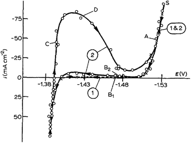 | ||
| Fig. 11 Polarization curves in the electrolyte (120 g l−1 H2SO4, 55 g l−1 Zn2+). Curve 1 (×): fresh electrolyte; curve 2 (○): after electrolysis for 12 h. Rotating disc electrode, Ω = 2500 rpm. The arrows on the curves indicate the direction of potential variation. Reprinted with permission from ref. 41. Copyright 1990, Springer. | ||
It is not common, but zero voltage could also be set between WE and reference electrode (RE).
Naderi et al. studied the inhibition synergism of new generations of new phosphate-based anticorrosion pigments.44 The role of zinc aluminum molybdenum orthophosphate hydrate (ZAM) and zinc calcium strontium aluminum orthophosphate silicate hydrate (ZCP) as new generations of phosphate-based anticorrosion pigments in corrosion protection of mild steel exposed to 3.5% sodium chloride solution was studied using electrochemical techniques, including EN measurements. Fig. 12 presents the time records of the electrochemical current noise for the steel specimens after 24 hours of immersion of coated steel in different solutions. ZAM and ZCP provide better corrosion inhibition comparing to zinc phosphate (ZP) coating as shown from the smaller amplitudes of EN signals (Fig. 12).44 This method is applied in studying the anti-corrosion of steel in 1 M H2SO4 solution by using Aloe plant extract.45
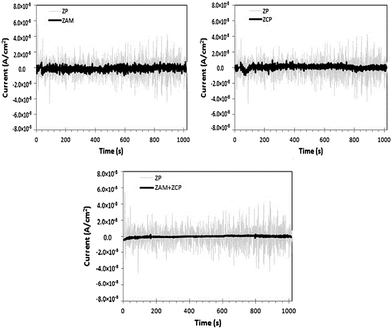 | ||
| Fig. 12 Time records of electrochemical current noise in the presence of different anticorrosion pigments. Reprinted with permission from ref. 44. Copyright 2014, Elsevier. | ||
Mojica et al. evaluated thick industrial coating films using EIS and electrochemical noise analysis.46 Three industrial coating systems were tested: a water-borne system; a zinc inorganic primer coated with epoxy and polyurethane topcoat; and a urethane elastomer. The samples were exposed in a salt fog chamber in accordance with the ASTM B 117-90 standard for 3000 h, and were removed to evaluate the effect of exposure times.46 After each exposure period, the samples were inspected visually according to both ASTM D 714 (blistering) and ASTM D 610 (rust). Then, electrochemical impedance spectroscopy (EIS) and electrochemical noise (EN) analyses were carried out. The experimental setup for EN consists of two identical working electrodes and a calomel reference electrode; all of them were immersed in 0.5 M NaCl solution at 20 °C. The electrochemical potential noise (EPN) is identified as the potential between one working electrode and the reference electrode. The electrochemical current noise (ECN) is the current between two working electrodes. The noise resistance was then calculated (Fig. 13).46
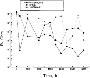 | ||
| Fig. 13 Noise resistance Rn as a function of exposure time in the salt fog chamber.46 Preprinted with permission from ref. 46. Copyright 2004, Maney Publishing). | ||
For the waterborne system, which failed on visual inspection after exposure for 500 h, the initial Rn values were decreased by four orders of magnitude after only 150 h. It then increased after 500 h and declined again after 1000 h. Beyond 1750 h, very low values of 104 to 105 ohms were assumed. These changes in slope provide a clear indication that this coating loses its anticorrosive properties. As for the zinc primer coated with epoxy and polyurethane topcoats, the initial value of R decreased by two orders of magnitude after 500 h, maintaining an average value of 106 ohm between 500 and 2000 h, after which the Rn value increased to 107 ohm until the end of the test. The best performance was observed from the urethane coating, for which the Rn values decreased significantly only after 2000 hours of testing, possibly due to water uptake.46
In general, to obtain a valid conclusion, the comprehensive use of at least two electrochemical methods is necessary. In case of studying corrosion on Zn and its alloys, the EVT, EIS, LP and corrosimetry are commonly used in the literature.
3.2 Non-electrochemistry methods
Beside the electrochemistry methods, which require electrochemical workstation to implement, there are non-electrochemistry methods which may be able to apply in studying corrosion. These methods may be accompanied with electrochemical means to provide insights of the corrosion process.E. D. Mor and A. M. Beccaria studied the inhibitory effect of acrylonitrile on the corrosion of zinc in sea water. Weight loss of zinc in sea water at different pH was measured. Smaller mass loss was observed when using acrylonitrile as the dopant. The functioning mechanism of acrylonitrile is elucidated via ATR method. Acrylonitrile forms a thin film on the zinc surface, and partially polymerizes to afford polyacrylonitrile. The interaction of nitrile toward zinc is classified as chemisorption.47
This method is also used in monitoring the performance of electroplating.48
3.3 Other methods
The other characterization methods listed below, but not limit to, are used in studying corrosion.Raman spectroscopy: this method works on the basis of detection of changes in polarizability, both ex situ and in situ.60
4. Corrosion protections of zinc and zinc alloys by polymer-containing materials, and their preliminary use in batteries
In this part, the use of electrochemically active conducting polymers for corrosion inhibition of zinc and its alloys is discussed. With metal and alloy foil, coating is a feasible method. Coating layers containing electrochemically active organic polymers provide several advantages comparing to inorganic coatings: (i) easy casting, moulding, and depositing at controllable thickness, (ii) easy mixing with zinc and zinc alloy particles, (iii) high flexibility, (iv) environment friendly, and (v) low costs.61 Beside coating, polymer-containing additives may be added in the electrolytes and such polymers may provide corrosion inhibition effects by adsorption on the metal surface. In printable batteries and zinc–air batteries, metal and alloy powders may be used as the negative electrode, polymer-containing materials can be used to make slurry, paste, or gel systems, in which the polymers act as corrosion inhibitors and binding agents via direct interaction with the anode surface. In many cases, the zinc batteries using polymer-containing materials as additives in electrolytes exhibit higher cyclability, stability than those used mercury containing anode.4.1 Polypyrrole
Polypyrrole was deposited on zinc by electropolymerization in a sodium tartrate aqueous solution. Homogeneous and strongly adherent polypyrrole coating has been achieved and confirmed with various analytical techniques.62 Using this technique, the coated zinc was passivated by the formation of a tartrate anion layer on its surface. Aqueous sodium oxalate containing a small amount of sulphide ion at pH 5 can be used instead of sodium tartrate.63 The best salts to be used in electrolyte with pyrrole for the electropolymerization may be sodium salicylate, which creates a thin protective layer on the zinc surface without affecting zinc's electrochemistry performance. When using sodium salicylate, an ultra-fast electropolymerization of pyrrole (thickness of 1 μm s−1 at 500 mA cm−2) can be conducted to deliver stable and adherent thin polypyrrole films.64For the corrosion protection of 55% Al–Zn-coated steel, a dense polypyrrole (PPy) film was electrochemically formed on 55% Al–Zn-coated steel in an acidic tartrate (0.5 M) solution. Anodic electropolymerisation of pyrrole was performed under a constant current control in the range of 1.0 to 5.0 mA cm−2 in the tartrate solutions with 0.6 M concentration of monomer. The range of pH values was 1.5–8.4. No corrosion products were observed during 60 h immersion of polypyrroled coated products in 3.5 wt% NaCl aqueous solution. When polymerization was conducted in the tartrate solution with sodium molybdate (5 mM), the resulting polymer is denser and the surface particles are smaller. Open circuit potential results reveal that coatings with sodium molybdate shows longer protection time than the coating without the existence of sodium molybdate.65
Beside galvanostatic method, polypyrrole can be deposited onto the zinc surface by potentiostatic electropolymerization of pyrrole in aqueous solution contaning tartrate anion.66
4.2 Polyacrylonitrile
To the best of our knowledge, the electrodeposition of polyacrylonitrile on zinc surface has not yet been reported in any literature. Polyacrylonitrile is a good candidate because it is electroactive, classified as non-toxic materials,67 and synthesized from acrylonitrile monomer through one-step polymerization.In the zinc corrosion study in sea water environment with acrylonitrile additive as the corrosion inhibitor, polyacrylonitrile was detected on the surface of zinc by mean of vibrational spectroscopy.47 The polymer is formed from chemisorbed acrylonitrile on the zinc surface, which underwent a self-polymerization to deliver a thin film, and this thin film protects the underneath zinc metal surface.
4.3 Polyaniline and its composites
Polyaniline films were successfully synthesized on zinc-electroplated steel sheets in 1 M sodium salicylate aqueous medium (pH ≈ 8) at different potentials (1.4–2.0 V).68 This one-step aniline electropolymerization process delivers polyaniline coating, which is compact and exhibiting uniform morphology, confirmed by mean of SEM. Potentiodynamic polarization curves of bare zinc-electroplated steel and PANI coatings obtained under different potentials in 3 wt% NaCl solution with scan rate of 0.01 V s−1 are displayed in Fig. 14. Tafel fit was conducted, and data are presented in Table 2.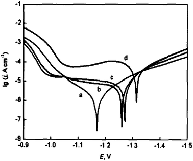 | ||
| Fig. 14 Potentiodynamic polarization curves: (a) PANI coatings formed at E = 1.4 V; (b) PANI coatings formed at E = 1.8 V; (c) PANI coatings formed at E = 2.0 V; (d) bare zinc-electrodeposited steel. Reprinted with permission from ref. 68. Copyright 2004, Acta Metallurgica Sinica, 2004. | ||
| Sample | Ecorr (V) | Icorr × 10−4 A cm−2 |
|---|---|---|
| Bare sheets | −1.314 | 9.516 |
| PANI coatings formed at E = 1.4 V | −1.170 | 1.248 |
| PANI coatings formed at E = 1.8 V | −1.260 | 1.431 |
| PANI coatings formed at E = 2.0 V | −1.272 | 1.542 |
Another method is to grow a polyaniline layer on top of a polypyrrole layer.69 The first step is the rapid electrodeposition of a thin polypyrrole film. It acts as a quick pre-treatment (generally less than 2 s) of the surface and completely modifies its electrochemical response to usual acidic solutions suitable for aniline electropolymerization. Pre-treated mild steel or zinc substrates can then be used for the electrodeposition of a PANI film of controllable thickness. No or very little metal oxidation occurs in this second step. The synthesized films show stable electroactivity in acidic electrolytes, similar to that of PANI deposited on platinum, which indicates that the underlying reactive metal is fully protected from oxidation. Despite the poor adhesion between the two polymer layers, the protecting capability is respectable. Prior to this, Lacaze and co. workers reported that the direct growth of polyaniline film on zinc–nickel alloys surface by electropolymerization was not very successful because the coated product is not conductive.70 The electro-deposition of polyaniline from oxalic or tosilic acid solutions failed, because created thin zinc oxalate (tosylate) layer prevents further electrochemistry and aniline monomer cannot be electro-oxidized to yield polyaniline.
Pruna and Pilan deposited polyaniline on top of a polypyrrole coated zinc at different preparation condition.71 The products were characterized by FTIR spectroscopy, SEM, OCV, and LP in 3.5 wt% NaCl aqueous solution. LP data were fitted by Tafel method to yield Ecorr (mV) and Jcorr (mA cm−2), which are presented on Table 3.
| Coating | Eoc (mV) | Ecorr (mV) | Jcorr (mA cm−2) |
|---|---|---|---|
| No coating | −841 | −860 | 0.68 |
| PPY (at 25 mA cm−2) | −772 | −777 | 0.42 |
| PPY (at 15 mA cm−2) | −572 | −571 | 0.17 |
| PANI (1 mA cm−2)/PPY (25 mA cm−2) | −530 | −537 | 0.28 |
| PANI (1 mA cm−2)/PPY (25 mA cm−2) | −518 | −532 | 0.083 |
| PANI (1 mA cm−2)/PPY (25 mA cm−2) | −490 | −503 | 0.033 |
Polyaniline–zinc composites and nanocomposites were prepared using solution mixing method. Zinc particles with an average particle size of 60 μm and zinc nanoparticles with an average particle size of 35 nm were used as fillers in polyaniline (PANI) matrix at different loadings of zinc particles. The composites were characterized by PXRD, FTIR, and SEM. Electrical conductivity was measured by four point method. OCV, LP in 0.1 M HCl, and the Tafel fit were conducted with composites coated on iron. The results show that the PANI–Zn nanocomposite films and coatings exhibit better electrical conductivity and corrosion protection on iron coupons compared to that of PANI–Zn composite.72
4.4 Other polymer-containing systems
![[thin space (1/6-em)]](https://www.rsc.org/images/entities/char_2009.gif) 000, 24
000, 24![[thin space (1/6-em)]](https://www.rsc.org/images/entities/char_2009.gif) 500, and 40
500, and 40![[thin space (1/6-em)]](https://www.rsc.org/images/entities/char_2009.gif) 000), and poly-2-vinylpyridines (M = 285
000), and poly-2-vinylpyridines (M = 285![[thin space (1/6-em)]](https://www.rsc.org/images/entities/char_2009.gif) 000).78 It was shown using the weight-loss technique that the studied polymers impart significant inhibiting effects on the corrosion rates of zinc metal. The protection efficiency in the presence of such polymers reached about 87% at an inhibitor concentration of 0.1 M. Polyvinylpyrrolidone with smaller molecular weights exhibit higher protecting performance than its high molecule weight counterparts. The corrosion rate of zinc using poly-4-vinylpyridine as an inhibitor is lower than in the case using a comparable concentration of poly-2-vinylpyridine. From OCV measurements, it is concluded that the corrosion process is partially cathodically controlled. The results are analysed in terms of the formation of a protective film on the metal surface.
000).78 It was shown using the weight-loss technique that the studied polymers impart significant inhibiting effects on the corrosion rates of zinc metal. The protection efficiency in the presence of such polymers reached about 87% at an inhibitor concentration of 0.1 M. Polyvinylpyrrolidone with smaller molecular weights exhibit higher protecting performance than its high molecule weight counterparts. The corrosion rate of zinc using poly-4-vinylpyridine as an inhibitor is lower than in the case using a comparable concentration of poly-2-vinylpyridine. From OCV measurements, it is concluded that the corrosion process is partially cathodically controlled. The results are analysed in terms of the formation of a protective film on the metal surface.Other polymers, such as cellulose, carboxyl methyl cellulose, polyethylene oxide… may be used as additives, or gelling agents for aqueous gel electrolytes to protect the zinc anode from corrosion.
4.5 Preliminary of polymer-coated zinc, polymer–zinc composites, and polymer-containing additives in rechargeable batteries
To the best of our knowledge, there is not any publication which uses polymer-containing materials for corrosion inhibition in ReHAB, since the system was introduced just few years ago. However, zinc–polymer composites have been applied in other types of battery manufacturing for decades, especially in the production of printable electrodes for thin film batteries. Sullivan reported that a flat zinc anode used in cells and batteries, e.g., Leclanche batteries, is produced by coating an electrically conductive substrate with a slurry containing zinc dust and an aqueous polymer latex in which the polymer particles have been swollen by an alcohol. The amount of the swollen polymer is about 0.5 to 5 weight per cent depending on the amount of zinc dust used. The amount of polymeric binder is not sufficient to form a continuous film, but rather it creates an adhesive mass which holds the zinc dust particles in place. Many polymers are suitable for use as binders, and it is presently preferred to employ polymers that do not react with Zn, e.g., soft vinyl polymers, acrylates, or elastomers, to impair battery performance or stability of the mix.79Zinc has been using as the anode in other types of aqueous secondary batteries, such as zinc–polymer, zinc–manganese dioxide, and zinc–air batteries. Typical works will be introduced below, including corrosion inhibition efforts exploiting polymer-containing materials or additives, which are introduced into the battery systems via anode assembly, electrolyte additives, or gelling agents.
Other aqueous zinc–polymers batteries were reported in the literature, such as zinc–polypyrrole,83 zinc-radical polymer,84 and zinc–copolymers.85
Corrosion on the zinc anode in the zinc–polyaniline batteries can be mitigated by adding 0.33 M of sodium citrate into 0.2 M ZnCl2 and 0.50 M NH4Cl aqueous electrolyte. Addition of citrate introduces a negative shift of 150 mV of open circuit potential for the zinc electrode. Furthermore, exchange current density decreases for more than order of magnitude and the increase of cathodic Tafel slope, due to the complexation of zinc ions, are observed. Zinc dendrite formation was completely suppressed.86 The use of polymer-containing materials as additives in electrolytes of Zn–PANI batteries were proved effective in suppressing zinc dendrite growth.87
Recent work reported this type of battery using neutral and slightly acidic electrolytes containing zinc sulphate or zinc nitrate (Fig. 15).90 Such electrolytes have pH in the range of 4–5, thus, they are not as chemically corrosive as alkaline electrolytes do. The authors of this work conducted a soft-packed type cell and no significant deformation was observed when the batteries were running. This means the gas generation is negligible. The same group has conducted further work regarding corrosion inhibition of Zn anode by employing surfactant and polymer-containing electrolytes.91 From gravimetric and electrochemical analysis, the authors confirm that co-usage of 0.05% hexadecyl trimethyl ammonium bromide (CTAB) and 0.05% polyethylene glycol nanowire (NPEG) in 1 M ZnSO4 solution decreases the corrosion effect by ca. 70%, which is better than employing CTAB or NPEG only. This suggests the synergistic effect between CTAB and NPEG. While CTAB electrochemically changes the system by initiating a negative shift of corrosion potential of zinc, NPEG provides physically changes by forming a very thick and hydrophobic layer on the zinc surface via adsorption. NPEG renders part of CTAB cations to create large micelle particles along the NPEG macromolecular chains and cross-link with NPEG, and thus greatly enhance the blocking effect of the hydrophobic layer.
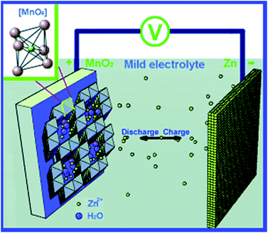 | ||
| Fig. 15 Schematics of the chemistry of the zinc ion battery. Zn2+ ions migrate between tunnels of an α-MnO2 cathode and a Zn anode. The inset in the upper left corner shows the structural basic unit of the MnO6 octahedron of MnO2. Reprinted with permission from ref. 90. Copyright 2012, Wiley. | ||
Recently, a zinc–air battery was constructed by printing the zinc–carbon–polymers on a current collector. The effects of different zinc–carbon–polymer combinations, differences in application method for the zinc–carbon composite, and various electrolyte compositions are discussed with an aim to apply in zinc–air batteries containing aqueous electrolyte.98
5. Conclusions
Corrosion on zinc and its alloys may be inhibited by using electroactive polymer coatings. Alternatively, zinc and its alloys in nanoparticles can be mixed with polymer micelles or immerged in polymer-containing electrolytes, which provide corrosion protection. Such protection effects were quantified and confirmed by various electrochemistry and non-electrochemistry techniques. The knowledge may help researchers in future to build new generations of efficient rechargeable aqueous batteries using Zn and Zn alloys as the anode active materials.Acknowledgements
This work was financially supported by Positec, Nature Sciences and Engineering Research Council of Canada (NSERC), Canada Foundation for Innovation (CFI), Canada Research Chair (CRC) Program, The University of Waterloo, and Mitacs (IT04444).Notes and references
- X. G. Zhang, Corrosion and Electrochemistry of Zinc, Plenum Press, New York, 1996 Search PubMed; M. Pourbaix, Lectures on Electrochemical Corrosion, Plenum Press, New York, 1973 Search PubMed.
- A. Mathiazhagan and R. Joseph, Int. J. Chem. Eng. Appl., 2011, 2, 255 Search PubMed.
- G. M. Spinks, A. J. Dominis, G. G. Wallace and D. E. Tallman, J. Solid State Chem., 2002, 6, 85 CAS.
- J. Jan, J. Wang, H. Liu, Z. Bakenov, D. Gosselink and P. Chen, J. Power Sources, 2012, 216, 222 CrossRef PubMed.
- G. Yuan, J. Bai, T. N. L. Doan and P. Chen, Mater. Lett., 2014, 137, 311 CrossRef CAS PubMed.
- H. Zhang, X. Wu, T. Yang, S. Liang and X. Yang, Chem. Commun., 2013, 49, 9977 RSC.
- N. Alias and A. A. Mohamad, J. Power Sources, 2015, 274, 237 CrossRef CAS PubMed.
- K. Wippermann, J. W. Schultze, R. Kessel and J. Penninger, Corros. Sci., 1991, 32, 205 CrossRef CAS.
- M. S. Rahmanifar, M. F. Mousavi, M. Shamsipur and M. Ghaemi, J. Power Sources, 2004, 132, 296 CrossRef CAS PubMed.
- Y.-D. Cho and G. T.-K. Fey, J. Power Sources, 2008, 184, 610 CrossRef CAS PubMed.
- L. M. Baugh, Electrochim. Acta, 1979, 24, 657 CrossRef CAS.
- L. M. Baugh, Electrochim. Acta, 1979, 24, 669 CrossRef CAS.
- R. D. Amstrong and M. H. Bell, J. Electroanal. Chem. Interfacial Electrochem., 1974, 55, 201 CrossRef.
- T. Hurlen and K. P. Fischer, J. Electroanal. Chem. Interfacial Electrochem., 1975, 61, 165 CrossRef CAS.
- G. Faita, F. Mazza and G. Bianch, Role of water and ionic salvation in localized corrosion phenomena, in Localized Corrosion, National Association of Corrosion Engineers, Houston, 2974, pp. 34–44 Search PubMed.
- J. O. M. Bockris, Z. Nagya and A. Damjanovic, J. Electrochem. Soc., 1972, 119, 285 CrossRef CAS PubMed.
- K. F. Lorking, The corrosion of zinc, Mettalurgy Report No. 67, Department of Supply, Australian Defense Scientific Service, Melbourne, Australia, May 1967 Search PubMed.
- E. A. Anderson and C. E. Reinhard, Zinc, in The Corrosion Handbook, ed. H. H. Uhlig, John Wiley & Sons, New York, 1948, pp.331–346 Search PubMed.
- C. W. Robert, Metalurgia, 1961, 9, 57 Search PubMed.
- M. M. Amin, N. El-Bagoury, M. Saracoglu and M. Ramadan, Int. J. Electrochem. Sci., 2014, 9, 5352 CAS.
- S. Ganesan, G. Prabhu and B. N. Popov, Surf. Coat. Technol., 2014, 238, 143 CrossRef CAS PubMed.
- M. Stern and A. L. Geary, J. Electrochem. Soc., 1957, 104, 56 CrossRef CAS PubMed.
- M. Gavrila, J. P. Millet, H. Mazille, D. Marchandise and J. M. Cuntz, Surf. Coat. Technol., 2000, 123, 164 CrossRef CAS.
- C. Yao, W. Chen, T. Zhu, S. L. Tay and W. Gao, Surf. Coat. Technol., 2014, 249, 90 CrossRef CAS PubMed.
- K. Darowicki, Corros. Sci., 1995, 37, 913 CrossRef CAS.
- J.-P. Diard, B. Le Gorrec and C. Montella, Corros. Sci., 1998, 40, 495 CrossRef CAS.
- K. Darowicki, Corros. Sci., 1998, 40, 509 CrossRef CAS.
- E. Van Gheem, R. Pintelon, J. Vereecken, J. Schoukens, A. Hubin, P. Verboven and O. Blajiev, Electrochim. Acta, 2004, 49, 4753 CrossRef CAS PubMed.
- E. Van Gheem, R. Pintelon, A. Hubin, J. Schoukens, P. Verboven, O. Blajiev and J. Vereecken, Electrochim. Acta, 2006, 51, 1443 CrossRef CAS PubMed.
- T. Breugelmans, E. Tourwé, Y. Van Ingelgem, J. Wielant, T. Hauffman, R. Hausbrand, R. Pintelon and A. Hubin, Electrochem. Commun., 2010, 12, 2 CrossRef CAS PubMed.
- K. Darowicki and P. Ślepski, Electrochem. Commun., 2004, 6, 898 CrossRef CAS PubMed.
- L. Mészáros, G. Mészáros and B. Lengyel, J. Electrochem. Soc., 1994, 141, 2068 CrossRef PubMed.
- J.-P. Diard, B. Le Gorrec and C. Montella, J. Electrochem. Soc., 1995, 142, 3612 CrossRef PubMed.
- L. Mészáros, G. Mészáros and B. Lengyel, J. Electrochem. Soc., 1995, 142, 3612 CrossRef PubMed.
- A. Macías, Mater. Struct., 1991, 24, 456 CrossRef.
- J. Jankowski, J. Electrochem. Soc., 2003, 150, B181 CrossRef CAS PubMed.
- W. Durnie, R. De Marco, A. Jefferson and B. Kinsella, Corros. Sci., 2002, 44, 1213 CrossRef CAS.
- M. A. Amin, S. S. Abd El-Rehim, F. D. A. Aarão Reis and I. S. Cole, Ionics, 2014, 20, 127 CrossRef CAS.
- S. S. Abd El Rehim, E. E. Foad El-Sherbini and M. A. Amin, J. Electroanal. Chem., 2003, 560, 175 CrossRef CAS PubMed.
- N. Ebrahimi, M. Momeni, A. Kosari, M. Zakeri and M. H. Moayed, Corros. Sci., 2012, 59, 96 CrossRef CAS PubMed.
- C. Cachet and R. Wiart, J. Appl. Electrochem., 1990, 20, 1009 CrossRef CAS.
- W. P. Iverson, J. Electrochem. Soc., 1968, 115, 617 CrossRef CAS PubMed.
- P. R. Roberge, R. Beaudoin and V. S. Sastri, Corros. Sci., 1989, 29, 1231 CrossRef CAS.
- R. Naderi, S. Y. Arman and S. Fouladvand, Dyes Pigm., 2014, 105, 23 CrossRef CAS PubMed.
- M. Mehdipour, B. Ramezanzadeh and S. Y. Arman, J. Ind. Eng. Chem., 2015, 21, 318 CrossRef CAS PubMed.
- J. Mojica, F. J. Rodriguez, E. Garcia-Ochoa and J. Genesca, Corros. Eng., Sci. Technol., 2004, 39, 131 CrossRef CAS PubMed.
- E. D. Mor and A. M. Beccaria, Corros. Eng., Sci. Technol., 1973, 8, 25 CAS.
- C. Georges, E. Rocca and P. Steinmetz, Electrochim. Acta, 2008, 53, 4839 CrossRef CAS PubMed.
- G. Bech-Nielsen, Electrochim. Acta, 1998, 43, 21 CrossRef CAS.
- G. Bech-Nielsen, F. de Fontenay and H. Poulsen, Electrochim. Acta, 1997, 42, 1847 CrossRef CAS.
- S. Khireche, D. Boughrara, K. Kadri, L. Hamadou and N. Benbrahim, Corros. Sci., 2014, 87, 504 CrossRef CAS PubMed.
- P. Díaz-Arista, Y. Meas, R. Ortega and G. Trejo, J. Appl. Electrochem., 2005, 35, 217 CrossRef.
- L. Sziráki, E. Szocs, Z. Pilbáth, K. Papp and E. Kálmán, Electrochim. Acta, 2001, 46, 3743 CrossRef.
- T. Cohen-Hyams, Y. Ziengerman and Y. Ein-Eli, J. Power Sources, 2006, 157, 584 CrossRef CAS PubMed.
- S. Oesch and M. Faller, Corros. Sci., 1997, 39, 1505 CrossRef CAS.
- N. C. Hosking, M. A. Ström, P. H. Shipway and C. D. Rudd, Corros. Sci., 2007, 49, 3669 CrossRef CAS PubMed.
- Z. Cui, X. Li, K. Xiao, C. Dong, Z. Liu and L. Wang, Corrosion, 2014, 70, 731 CrossRef CAS PubMed.
- K. Aramaki, Corros. Sci., 2001, 43, 1985 CrossRef CAS.
- L. Philippe, C. Sammon, S. B. Lyon and J. Yarwood, Prog. Org. Coat., 2004, 49, 302 CrossRef CAS PubMed.
- M. C. Bernard, A. Hugot-Le Goff, D. Massinon and N. Phillips, Corros. Sci., 1993, 35, 1339 CrossRef CAS.
- D. E. Tallman, G. Spinks, A. Dominis and G. G. Wallace, J. Solid State Chem., 2002, 6, 73 CAS.
- M. Bazzaoui, L. Martins, E. A. Bazzaoui and J. I. Martins, J. Electroanal. Chem., 2002, 537, 47 CrossRef CAS.
- C. A. Ferreira, B. Zaïd, S. Aeiyach and P. C. Lacaze, in Organic Coatings, ed. P. C. Lacaze, AIP Press, Woodbury, New York, 1996, pp. 159–165 Search PubMed.
- J. Petitjean, S. Aeiyach, J. C. Lacroix and P. C. Lacaze, J. Electroanal. Chem., 1999, 478, 92 CrossRef CAS.
- H. Ryu, N. Sheng, T. Ohtsuka, S. Fujita and H. Kajiyama, Corros. Sci., 2012, 56, 67 CrossRef CAS PubMed.
- C. Pirvu, M. Mindroiu and I. Demetrescu, Key Eng. Mater., 2009, 415, 65 CrossRef CAS.
- MSDS of Polyacrylonitrile, Sigma Aldrich, Retrieved December 6th, 2014.
- Y. P. Zhao, R. H. Yin, W. M. Cao and A. B. Yuan, Acta Metall. Sin., 2004, 17, 849 CAS.
- J. C. Lacroix, J. L. Camelet, S. Aeiyach, K. Chane-Ching, J. Petitjean, E. Chauveau and P. C. Lacaze, J. Electroanal. Chem., 2000, 481, 76 CrossRef CAS.
- J. L. Camalet, J. C. Lacroix, S. Aeiyach, K. Chane-Ching and P. C. Lacaze, Synth. Met., 1998, 93, 133 CrossRef CAS.
- A. Pruna and L. Pilan, Composites, Part B, 2012, 43, 3251 CrossRef CAS PubMed.
- A. Olad, M. Barati and H. Shirmohammadi, Prog. Org. Coat., 2011, 72, 599 CrossRef CAS PubMed.
- J. Schinhelm, M. Giza, K. Nikolov, N. Weiher, B. Schuhmacher and C.-P. Klages, Surf. Coat. Technol., 2011, 205, S137 CrossRef PubMed.
- D. Vasilakopoulos and M. Bouroushian, Surf. Coat. Technol., 2010, 205, 110 CrossRef CAS PubMed.
- O. Kammona, K. Kotti, C. Kiparissides, J. P. Celis and J. Fransaer, Electrochim. Acta, 2009, 54, 2450 CrossRef CAS PubMed.
- A. Hovestad, R. J. C. H. L. Heesen and L. J. J. Janssen, J. Appl. Electrochem., 1999, 29, 331 CrossRef CAS.
- N. Boshkov, N. Tsvetkova, P. Petrov, D. Koleva, K. Petrov, G. Avdeev, C. Tsvetanov, G. Raichevsky and R. Raicheff, Appl. Surf. Sci., 2008, 254, 5618 CrossRef CAS PubMed.
- A. El-Khair, B. Mostafa, S. M. Abdel-Wahaab and E.-S. M. Mabrouk, Surf. Coat. Technol., 1986, 27, 317 CrossRef.
- C. I. Sullivan, US Pat. No US3954506 A, May 4th, 1976.
- A. G. Macdiarmid, S.-L. Mu, N. L. D. Somasiri and W. Wu, Mol. Cryst. Liq. Cryst., 1985, 121, 187 CrossRef CAS PubMed.
- M. Sima, T. Visan and M. Buda, J. Power Sources, 1995, 56, 133 CrossRef CAS.
- A. Guerfi, J. Trottier, I. Boyano, I. De Meatza, J. A. Blazquez, S. Brewer, K. S. Ryder, A. Vijh and K. Zaghib, J. Power Sources, 2014, 248, 1099 CrossRef CAS PubMed.
- B. N. Grgur, M. M. Gvozdenović, J. Stephanović, B. Z. Jugović and V. M. Marinović, Electrochim. Acta, 2008, 53, 4627 CrossRef CAS PubMed.
- K. Koshita, N. Sano, K. Oyaizu and H. Nishide, Macromol. Chem. Phys., 2009, 210, 1989 CrossRef CAS PubMed; T. Janoschka, M. D. Hager and U. S. Schubert, Adv. Mater., 2012, 24, 6379 CrossRef PubMed; H. Nishide and K. Oyaizu, Science, 2008, 319, 737 CrossRef PubMed.
- K. Oyaizu, H. Tatsuhira and H. Nishide, Polym. J., 2015, 47, 212 CrossRef CAS.
- B. Z. Jugović, T. L. Trišović, J. Stevanović, M. Maksimović and B. N. Grgur, J. Power Sources, 2006, 160, 1447 CrossRef PubMed; B. Z. Jugović, M. Gvozdenović, J. Stevanović, T. Trišović and B. N. Grgur, Mater. Des., 2009, 30, 3291 CrossRef PubMed.
- J. Kan, H. Xue and S. Mu, J. Power Sources, 1998, 74, 113 CrossRef CAS.
- K. Kordesch and M. Weissenbacher, J. Power Sources, 1994, 51, 61 CrossRef CAS.
- H. Zhou, Q. Huang, M. Liang, D. Lu, M. Xu, H. Li and W. Li, Mater. Chem. Phys., 2011, 128, 214 CrossRef CAS PubMed; V. K. Nartey, L. Binder and K. Kordesch, J. Power Sources, 1994, 52, 217 CrossRef.
- C. Xu, B. Li, H. Du and F. Kang, Angew. Chem., Int. Ed., 2012, 51, 933 CrossRef CAS PubMed.
- H. Li, B. Ki, C. Xu, C. Wei and F. Kang, Mater. Sci. Forum, 2012, 722, 17 CrossRef CAS.
- J.-S. Lee, S. T. Kim, R. Cao, N.-S. Choi, M. Liu, K. T. Lee and J. Cho, Adv. Energy Mater., 2011, 1, 34 CrossRef CAS PubMed.
- C. W. Lee, K. Sathiyanarayanan, S. W. Eom and M. S. Yun, J. Power Sources, 2006, 160, 1436 CrossRef CAS PubMed.
- C. W. Lee, K. Sathiyanarayanan, S. W. Eom, H. S. Kim and M. S. Yun, J. Power Sources, 2006, 160, 1474 CrossRef PubMed.
- R. Othman, W. J. Basirun, A. H. Yahaya and A. K. Arof, J. Power Sources, 2001, 103, 34 CrossRef CAS.
- S. Müller, F. Holzer and O. Haas, J. Appl. Electrochem., 1998, 28, 895 CrossRef.
- M. C. Cheiky, US Pat. No US4957286 A, 1990.
- M. Hilder, B. Winther-Jensen and N. B. Clark, J. Power Sources, 2009, 194, 1135 CrossRef CAS PubMed.
| This journal is © The Royal Society of Chemistry 2015 |


