
Incorporation of PEDOT:PSS into SnO2/reduced graphene oxide nanocomposite anodes for lithium-ion batteries to achieve ultra-high capacity and cyclic stability†
Md. Selim Arif Sher Shah‡
a,
Shoaib Muhammad‡b,
Jong Hyeok Parkac,
Won-Sub Yoon*b and
Pil J. Yoo*ac
aSchool of Chemical Engineering, Sungkyunkwan University, Suwon 440-746, Republic of Korea. E-mail: pjyoo@skku.edu
bDepartment of Energy Science, Sungkyunkwan University, Suwon 440-746, Republic of Korea. E-mail: wsyoon@skku.edu
cSungkyunkwan Advanced Institute of Nanotechnology, Sungkyunkwan University, Suwon 440-746, Republic of Korea
First published on 22nd January 2015
Abstract
SnO2, a candidate material for anodes in Li-ion batteries (LIBs), usually suffers from severe volume change (>300%) during charge–discharge cycles. This problem leads to undesirable continuous capacity fading, hindering its practical utilization. To address this issue, nanostructured SnO2 and its composites with carbon nanomaterials, especially graphene, have extensively been studied. Although the stability issue has improved substantially, these materials still suffer from low capacity characteristics, which are far from the theoretical capacity of SnO2. Motivated by this background, in this work, we synthesized a novel ternary nanocomposite of SnO2, reduced graphene oxide (rGO), and a conducting polymer, poly(3,4-ethylenedioxythiophene)-poly(styrenesulfonate) (PEDOT:PSS), as a high performance anode material in LIBs. PEDOT:PSS together with rGO is expected to efficiently accommodate the volume change in SnO2 during cycling. Transmission electron microscopic observation reveals 2–3 nm-sized SnO2 nanoparticles are uniformly dispersed over rGO nanosheets while having a PEDOT:PSS coating. The capacities of the synthesized composites were dependent on the PEDOT:PSS concentration. The reversible capacity of the composite with 5 wt% PEDOT:PSS was maintained at 980 mA h g−1 with a coulombic efficiency over 99% even after 160 cycles. This capacity value is equivalent to 1185 mA h g−1 on the basis of only SnO2 in the composite. The high capacity of the ternary nanocomposites is attributed to the ultra-small size of SnO2 nanoparticles, enhanced electronic and ionic mobility, and facilitated volumetric relaxation synergistically offered by rGO nanosheets and the PEDOT:PSS coating.
Introduction
Since their successful industrial launch in the early 1990s, lithium ion batteries (LIBs) have quickly gained much of the market for consumer electronic devices.1–4 In particular, to meet a recent need for increased capacity in affordable mobile devices, a variety of non-carbon metallic species, such as Si (theoretical capacity ∼ 4000 mA h g−1),5–9 Ge (1600 mA h g−1),10–15 and Sn (∼992 mA h g−1),16,17 which can incorporate relatively more Li ions into the alloy to attain a high theoretical capacity, have been investigated to replace conventional graphite anodes. In parallel, researchers have sought a suitable oxide material that can store and deliver high energy. Among several materials, SnO2 is considered as an appealing anode material in LIBs because of its good physical and chemical stability, environmental-friendly nature, low Li ion intercalation potential, and high theoretical capacity (782 mA h g−1, but it may be as high as 1493 mA h g−1 under totally reversible conditions), which would be about four times greater than that of commercial graphite (specific capacity of 372 mA h g−1).18–24 Moreover, the potential of an SnO2 anode is also higher than that of graphite; thus, it reduces metallic lithium deposition on the anode during fast charging. However, the main drawback of a SnO2 anode is its severe volume change (>300%) between the fully lithiated and delithiated states. This leads to pulverization and structural collapse of the electrode, eventually resulting in a loss of electrical contacts between SnO2 particles and the current collector. As a result, continuous capacity fading occurs during cycling.21,25–27 Although nano-sized SnO2 can alleviate the pulverization problem to some extent, complete suppression has not yet been accomplished because the particle size below which the pulverization is totally absent is much smaller than the unit cell size of the SnO2. In addition, agglomeration of primary SnO2 nanoparticles decreases the binding sites for Li ions, which generates severe mechanical stress and decreases Li ion mobility, ultimately resulting in a loss of capacity.28–31 Moreover, a pure SnO2 anode suffers from low initial coulombic efficiency because of considerable irreversible reaction in the first cycle. Apart from this characteristic, it has been reported that electrochemically active Sn nanoparticles are formed as a result of partial reduction of SnO2 by Li ions during cycles. However, these Sn nanoparticles generally tend to aggregate into larger, inactive Sn clusters, resulting in deterioration of the reversible capacity of the electrode.32,33Composites of SnO2 with different carbon nanomaterials may be superior to SnO2 alone because the carbon materials act as a cushioning layer to buffer against volume change and to improve electrical conductivity of the composites. In this regard, graphene, a single-atom-thick planar carbon nanomaterial, is considered as a promising 2D material due to its excellent electrical conductivity, large surface area (>2600 m2 g−1), and high structural flexibility.34–36 Therefore, SnO2–graphene nanocomposites have extensively been studied as a promising anode material for advanced LIBs. However, the problem of pulverization and capacity fading has not been completely eliminated.37–39 Such a limitation indicates that there is still much room to increase the capacity of such composite systems.
A good strategy to overcome the limitation of SnO2–graphene composites is to make ternary nanocomposites, in which the third component further accommodates the volume change more efficiently in comparison to the binary composites. There are several reports where nanostructured SnO2 materials were sandwiched between graphene layers. For example, Prabakar et al. reported alternating stacks of SnO2 with graphene oxide (GO) and amine functionalized graphene, which showed an excellent capacity of 872 mA h g−1 after 200 cycles at a current density of 100 mA g−1.40 N-doped graphene–SnO2 sandwiched papers were demonstrated by Wang et al., wherein a capacity over 800 mA h g−1 at 50 mA g−1 after 50 cycles and enhanced cycle stability of the composite were reported.41 The excellent electrochemical behaviour was attributed to the N-doped graphene and optimized structural features. In another report, Sun et al. described sandwiched graphene–SnO2 nanorod-carbon nanostructures for ultra-high lithium storage properties.4 They achieved a capacity of 1419 mA h g−1 after 150 cycles at 0.1 C, as compared to 389 mA h g−1 for graphene–SnO2 nanorod complexes. Very recently, Bhaskar et al. demonstrated ternary composites of SnO2 hollow spheres with poly(3,4-ethylenedioxythiophene) (PEDOT) and graphene oxide.42 They reported a capacity of 608 mA h g−1 at a current density of 100 mA g−1 after 150 cycles. Since they employed non-electroconductive graphene oxide instead of graphene or reduced graphene oxide, obtained capacity value was relatively low. To date, only a few reports have described a capacity that is close to the theoretical value of SnO2. In this regard, there is an urgent need to develop new electrode materials possessing remarkably enhanced capacities and high rate performance for development of the next-generation LIBs.
In the present work, we report ternary composites of SnO2 nanoparticles with PEDOT:PSS and reduced graphene oxide (rGO). The composites were synthesized through simple yet robust one-pot wet chemical method, namely, complexation and precipitation of SnO2 nanoparticles on rGO under reflux followed by the addition of PEDOT:PSS (Scheme 1). The synthetic conditions are mild, and the maximum temperature of 100 °C lasts for 1.5 h, followed by heating at 65 °C for 15 h; water is used as the only solvent. Under these synthetic conditions, we obtained small SnO2 nanoparticles (2–3 nm in size) while excluding the use of surfactants or harsh chemicals. The ultra-small SnO2 nanoparticles are uniformly distributed over rGO nanosheets and the composites are stably enwrapped with PEDOT:PSS. As a result, the undesirable tendency of SnO2 nanoparticles to self-agglomerate was largely eliminated. Moreover, the ultra-small SnO2 nanoparticles led to a decrease in the lithium diffusion length, which, together with the efficient accommodation of volume change of SnO2 during charge–discharge cycles, ultimately gives rise to high capacity. Accordingly, the ternary nanocomposite shows high lithium storage capacity and excellent capacity retention characteristics, which are much greater than those of SnO2-based binary composites. The specific capacities of the ternary composites vary depending on the amount of PEDOT:PSS.
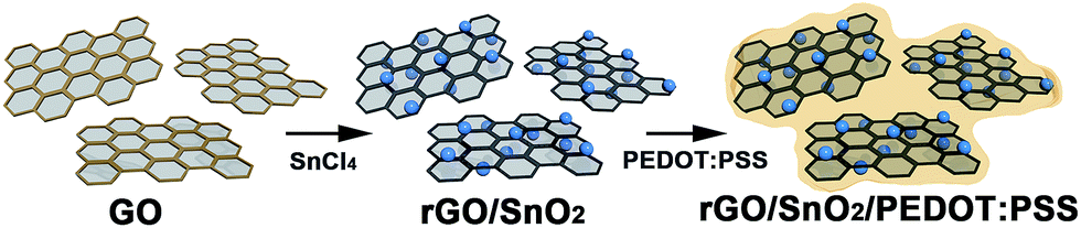 | ||
| Scheme 1 Synthetic procedure of ternary nanocomposites of rGO/SnO2/PEDOT:PSS. | ||
Experimental section
Materials
Graphite powder (<20 μm, synthetic), poly(3,4-ethylenedioxy-thiophene-poly(styrenesulfonate) (PEDOT:PSS) and tin tetrachloride (SnCl4) were purchased from Sigma-Aldrich. NaNO3 (99.0%) was obtained from Yakuri Pure Chemicals Co. Ltd., Japan. H2SO4 (95.0%), KMnO4 (99.3%), and H2O2 (34.5%) were purchased from Samchun Chemical Co. Ltd., Korea. All the chemicals were used as received. In all experiments, deionized water of resistance 18.2 MΩ was used.Synthesis
GO was synthesized using a modified Hummers' method, which is described elsewhere.43,44 In a typical synthesis of the ternary composites, 30 ml of a GO (1.5 mg ml−1) dispersion in water was mixed with 45 ml deionized (DI) water. The resulting dispersion was sonicated for 1 h and was cooled in a refrigerator. Then, 0.15 ml SnCl4 was added drop-wise to the dispersion under vigorous stirring. Gentle stirring was continued for over 1 h while maintaining a temperature below 5 °C. The solution was then refluxed in a 250 ml round bottom flask. After 1.5 h, the temperature was decreased to 65 °C and PEDOT:PSS was added. Stirring was continued at that temperature for 15 h more. The dark blue solution was cooled to room temperature and the precipitate was washed with copious amounts of water to remove residual Cl− ions. The product was dried at 60 °C overnight. Hereafter, samples will be denoted as GSP-x, where x is the weight% of PEDOT:PSS in the composites. For comparison, SnO2, rGO/SnO2 (GS), and SnO2/PEDOT:PSS (SP) were also synthesized following the same experimental conditions, including the same amount of the reactants, without the addition of GO and/or PEDOT:PSS, depending on the type of the composite.Characterization
Powder X-ray diffraction (XRD) patterns were obtained (D8 Focus, Bruker Instruments, Germany) using Cu Kα radiation (λ = 1.5406 Å) in the 2θ range from 2 to 80° with a step size of 0.02° s−1. The accelerating voltage and the applied current were 40 kV and 40 mA, respectively. Scanning electron microscopy images were collected in a field-emission scanning electron microscope (FESEM, JSM-7600F, JEOL). Transmission electron microscopy was carried out with a TECNAI G2 instrument with an acceleration voltage of 300 kV. FTIR measurements (IFS-66/S, Bruker instrument, Germany) were carried out in transmittance mode in the spectral range of 400–4000 cm−1 with a resolution better than 0.1 cm−1. Raman spectra were taken using a Micro-Raman spectrometer system (ALPHA 300 M, WITec, Germany). The sample was loaded onto a silicon wafer and focused using a 50× objective. The spectra were taken in the range of 1–3000 cm−1. X-ray photoelectron spectroscopy (XPS) characterization was performed (ESCA 2000 instrument, VG Microtech, United Kingdom) using an Al Kα X-ray source. All binding energy values were corrected by calibrating the C 1s peak at 284.6 eV. High resolution peaks were deconvoluted using Gaussian–Lorentzian functions with identical full width at half maxima (fwhm) after a Shirley background subtraction. Photoluminescence data were collected using a Cary Eclipse Fluorescence Spectrophotometer (Agilent Technologies).Electrode preparation
A slurry was prepared by mixing 70 wt% active material with 15 wt% super P and 15 wt% polyvinylidene fluoride (PVdF, Sigma-Aldrich) with a few drops of N-methyl pyrrolidine (Sigma-Aldrich). The resulting slurry was then coated on a copper foil and dried at 60 °C for 10 h in a vacuum oven. Average loading of active material of each electrode prepared was 1.5 mg cm−2. CR 2032 type coin cells were assembled inside an argon-filled glovebox (O2 and H2O concentration ≤ 0.5 ppm) using a metallic lithium foil as the counter/reference electrode, and a piece of Celgard as the separator. The electrolyte was 1.3 M LiPF6 dissolved in a mixture of ethylene carbonate (EC) and dimethyl carbonate (DMC) (3![[thin space (1/6-em)]](https://www.rsc.org/images/entities/char_2009.gif) :7, v/v). The discharge–charge cycling tests were carried out at constant current rate of C/10 between 0.005 and 3.0 V using a battery test station (WBCS3000, WonATech Corp). Electronic conductivity of the electrodes was determined by electrochemical impedance spectroscopy in the frequency range from 20 mHz to 1 MHz using a multichannel electrochemical workstation (Zive MP2, WonATech Corp).
:7, v/v). The discharge–charge cycling tests were carried out at constant current rate of C/10 between 0.005 and 3.0 V using a battery test station (WBCS3000, WonATech Corp). Electronic conductivity of the electrodes was determined by electrochemical impedance spectroscopy in the frequency range from 20 mHz to 1 MHz using a multichannel electrochemical workstation (Zive MP2, WonATech Corp).
Results and discussion
Crystallographic phases of the synthesized materials were characterized by powder X-ray diffraction measurements. Therein, (110), (101), (211), and (112) planes of SnO2 were observed respectively, at 2θ values of 26.5, 33.9, 51.8, and 64.9°, as depicted in Fig. 1a.45 These results confirm that the synthesized SnO2 is rutile (JCPDS card number 1-625). Unit cell parameters are a = b = 4.688, and c = 3.216 Å.45 The crystallite size was calculated to be 2.5 nm as determined using the Scherrer formula using (110) planes. These results prove the successful synthesis of ultra-small SnO2 nanoparticles following a mild synthetic route. X-ray diffractograms of GS and rGO/SnO2/PEDOT:PSS (GSP) are similar to those of SnO2. The only difference is that the peaks are broadened in GS and GSP as compared to SnO2. Chemical composition of the synthesized materials was confirmed by FTIR analysis. Fig. 1b shows FTIR spectra of GS, SP, and GSP. FTIR spectra of GS show C![[double bond, length as m-dash]](https://www.rsc.org/images/entities/char_e001.gif) C and O–H stretching vibrations at 1636 and 3430 cm−1, respectively.43,44 It further displays two peaks below 800 cm−1, which are due to Sn–O–Sn and O–Sn–O stretching vibrations.46 Apart from these peaks, the FTIR of SP shows peaks at 1205, 1136 and 1085 cm−1 for C–O–C stretching vibrations and peaks at 979, 932, and 842 cm−1 for C–S bond stretching of PEDOT:PSS.42 The FTIR spectrum of GSP is similar to that of SP.
C and O–H stretching vibrations at 1636 and 3430 cm−1, respectively.43,44 It further displays two peaks below 800 cm−1, which are due to Sn–O–Sn and O–Sn–O stretching vibrations.46 Apart from these peaks, the FTIR of SP shows peaks at 1205, 1136 and 1085 cm−1 for C–O–C stretching vibrations and peaks at 979, 932, and 842 cm−1 for C–S bond stretching of PEDOT:PSS.42 The FTIR spectrum of GSP is similar to that of SP.
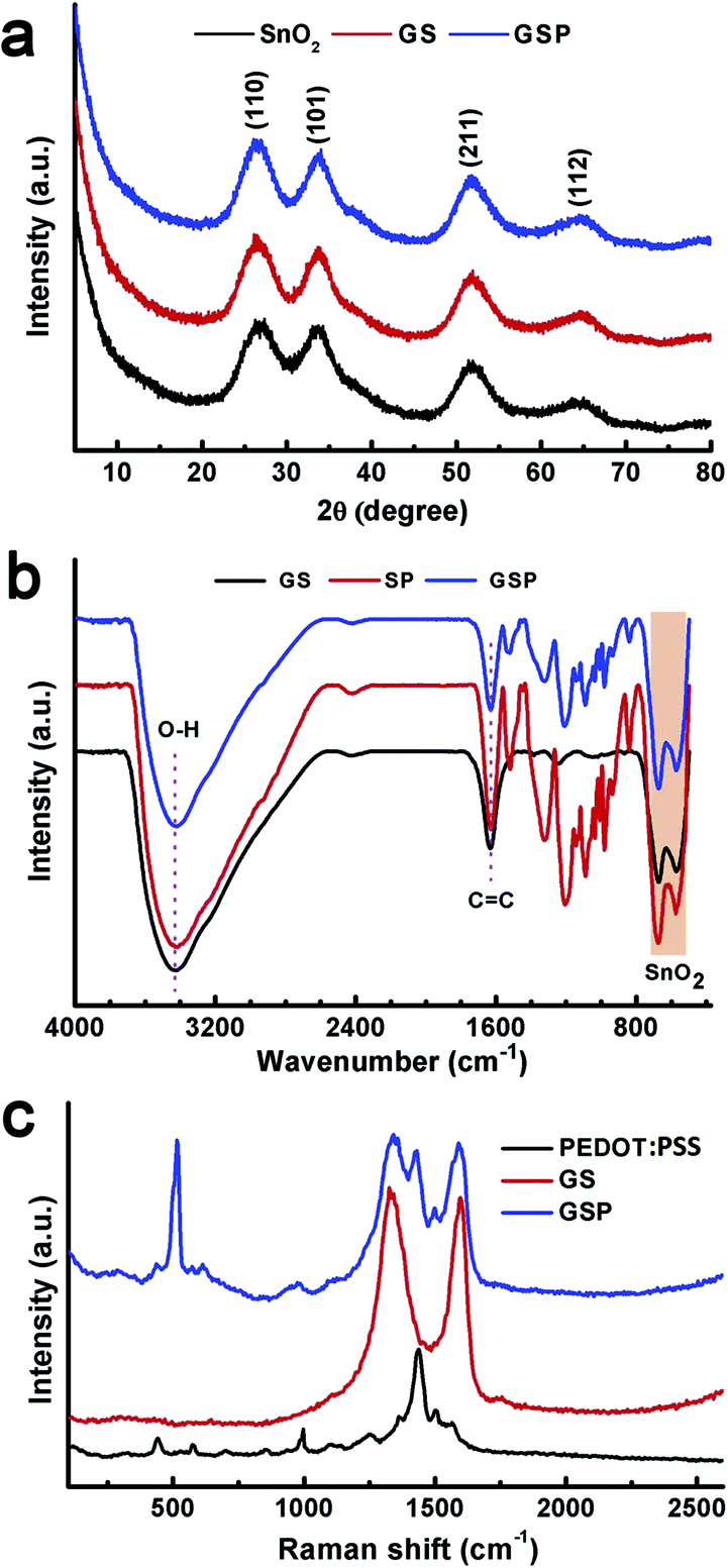 | ||
| Fig. 1 (a) X-ray diffractograms of SnO2, GS, and GSP. (b) FTIR spectra of GS, SP, and GSP. (c) Raman spectra of PEDOT:PSS, GS, and GSP. | ||
Raman spectral analysis was carried out to provide a detailed understanding of the chemical composition of the synthesized materials. As depicted in Fig. 1c, the Raman spectrum of PEDOT:PSS clearly shows bands at 1568 and 1503 cm−1 for the CαCβ asymmetric stretching mode, 1430 cm−1 for the symmetric CαCβ stretching frequency, 1361 cm−1 for the Cβ–Cβ stretching vibration, 1258 cm−1 for the Cα–Cα inter-ring stretching mode, 1097 cm−1 for C–O–C stretching, 994 and 579 cm−1 to oxyethylene ring deformation, 700 cm−1 for symmetric C–S–C deformation, and 441 cm−1 for SO2 bending vibration.47,42 Two main peaks are observed in the Raman spectra of GS at 1331 and 1598 cm−1, which are assigned, respectively, to the D- and G-band of graphene.48 The ternary composite, GSP, displays all the peaks present in PEDOT:PSS and GS.
X-ray photoelectron spectroscopy was used to further characterize the composites. The survey XPS spectrum of GSP5 (Fig. S1 in the ESI†) shows that the composite consists of Sn, C, O and S. Fig. 2a shows a high resolution C 1s XPS spectrum of the composite GSP. The peak at 284.6 eV is for the CC of graphene.43 The binding energy of C–OH of graphene and C–S of PEDOT:PSS in the α position is observed at 285.8 eV. CO of rGO and CC–O in the β position of PEDOT result in a peak at 287.06 eV.42 At the same time, the COOH peak of rGO and C–O–C bonding in the ethylene bridge of PEDOT occurs at 288.5 eV. The presence of PEDOT:PSS was further proven by characteristic XPS spectra of S 2p, as depicted in Fig. 2b. Spin–orbit splitting contributions of S 2p in PEDOT were found at 163.9 eV for S 2p3/2 and at 165.3 eV for S 2p1/2. Another doublet arises at 167.9 and 169.3 eV, respectively for S 2p3/2 and S 2p1/2 of PSS.49
 | ||
| Fig. 2 High resolution XPS spectra of (a) C 1s, (b) S 2p, and (c) Sn 3d of GSP. | ||
The higher energy doublet originated from positively charged sulphur of PSS because a highly electronegative oxygen atom is attached to the S atom. All sulphur contributions have a separation between 2p1/2 and 2p3/2 of ∼1.4 eV, which is close to the literature values. From the XPS spectrum of S, we can unequivocally conclude that the ternary composite contains PEDOT:PSS. Fig. 2c displays high resolution XPS spectra of Sn 3d. As shown, a doublet is observed at 487.6 and 496.0 eV for Sn 3d5/2 and 3d3/2, respectively.41 The separation between the two peaks of the doublet was determined to be 8.4 eV. These observations indicate that Sn is present as Sn4+ in the composite, i.e., as SnO2.
Fig. 3a shows a transmission electron microscope (TEM) image of the composite GSP. From the micrograph, it is evident that 2–3 nm SnO2 nanoparticles coexist with rGO and PEDOT:PSS. This result, apart from XRD analysis, further confirms the presence of ultra-small SnO2 nanoparticles in the composites. A high resolution TEM (HRTEM) micrograph of GSP shown in Fig. 3b clearly depicts highly crystalline and ultra-small SnO2 nanoparticles were obtained following a relatively mild synthetic procedure. TEM micrographs clearly show that the SnO2 nanoparticles do not form any obvious aggregation. This is an important property, particularly for battery applications, as it mitigates the risk of possible pulverization. Fringe lines with a spacing of 0.33 nm are clearly visible in Fig. 3b, implying (110) planes of rutile SnO2.50 Fig. 3c is a typical scanning electron microscope (SEM) image of the composite. In the inset in Fig. 3c, an energy dispersive X-ray spectrum (EDS) of the composite is provided, demonstrating that the composite consists of C, O, Sn and S. Elemental mapping is shown on the right side of c. The amount of SnO2 nanoparticles in the composite was determined by thermogravimetric (TG) analysis. Fig. S2† is a TG trace of GSP5 showing that the amount of SnO2 nanoparticles in the composite is ∼74%.
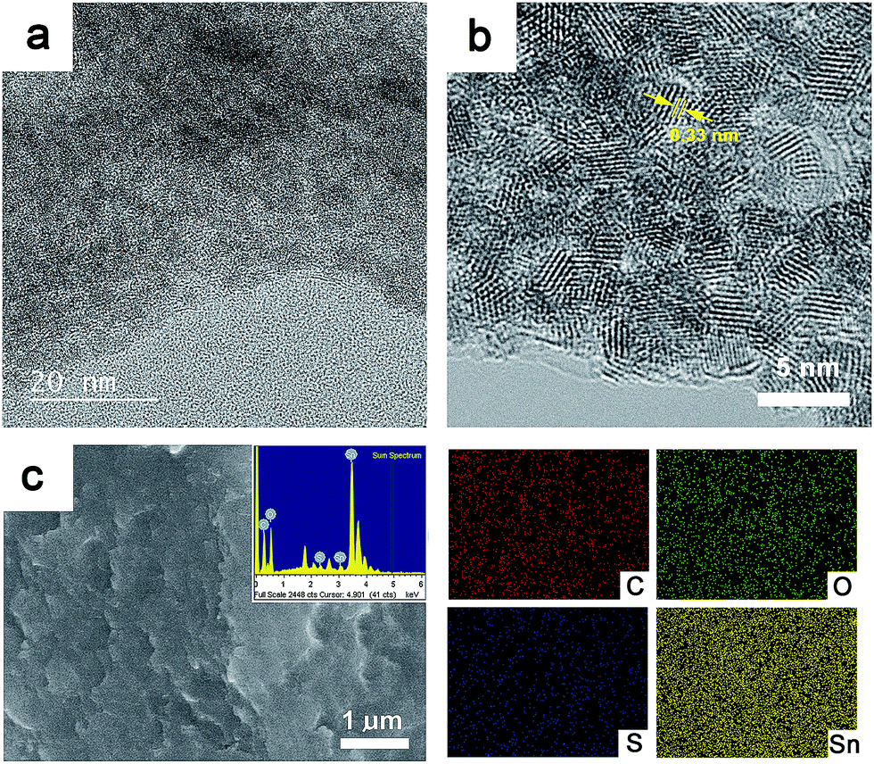 | ||
| Fig. 3 (a) TEM micrograph of GSP. (b) its HRTEM micrograph. (c) Typical SEM micrograph of the composite. Inset shows its EDS. Elemental mapping for C, O, S and Sn is also shown. For elemental mapping whole area in c was considered. | ||
Fig. 4a provides voltage curves of the as-synthesized pure SnO2 in the potential range of 0.005 to 3.0 V vs. Li/Li+ performed at constant current density of 80 mA g−1 (0.1 C). The first charge and discharge capacities were 624 and 1916 mA h g−1 with a coulombic efficiency of merely 32.6%. Other selected voltage profiles for SnO2 are also shown. Fig. 4b represents corresponding differential curves (dQ/dV). The differential curve (1st cycle) of SnO2 display two cathodic peaks at 1.05 and 0.22 V; the first peak corresponds to the reduction of SnO2 to Sn (reaction (4)), while the later peak is due to the alloying of Sn with Li according to reaction (5) and insertion of Li into rGO (reaction (6)).51,52 It is notable that there is a shoulder to the broad peak at 1.05 V. This may be due to the formation of a solid electrolyte interface (SEI). It may be noted that, in the second cycle, the reduction peak at 1.05 V disappears and a weak peak arises at 0.72 V, which may be due to the reduction of SnO2 to Sn. The first anodic cycle shows two peaks at 0.49 and 1.18 V, which are due to de-alloying of LixSn and oxidation of Sn to SnO2. In the second cycle, the oxidation peak at 1.18 V disappears, implying that only the conversion of Sn to LixSn occurs in the successive cycles.52 However, the alloying peak in the cathodic scan and de-alloying peak in the anodic scan exist in the second cycle. After repeated cycles (e.g. 50 times), intensities of all the peaks from both cathodic and anodic processes decrease largely and then nearly disappear after around 100 cycles.
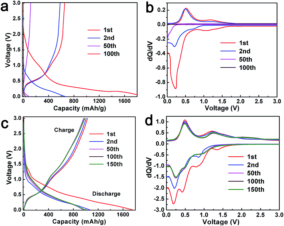 | ||
| Fig. 4 Charge–discharge profiles and the corresponding differential curves of (a and b) SnO2 nanoparticles and (c and d) GSP5. | ||
Galvanostatic charge–discharge profiles of the composite anode GSP5 were evaluated in the same condition as with pure SnO2. The first discharge and charge capacity achieved with the cell were 1759 and 1029 mA h g−1, as observed in Fig. 4c. Other representative charge–discharge profiles are also shown in Fig. 4c for the sake of comparison. To investigate the electrochemical processes occurring during charge–discharge cycles, plots of dQ/dV (known as differential capacity) vs. potential, known as differential curves, are displayed in Fig. 4d. A plateau in the charge–discharge curve appears as a peak in the differential curve. The plot of first discharge (cathodic) cycle exhibits four peaks at 1.32, 0.84, 0.42, and 0.18 V. The peak at 1.32 V indicates the reduction of the electrolyte and formation of a solid electrolyte interface (SEI) at the interface of the electrode and electrolyte. The broad peak at 0.84 V corresponds to the reduction of SnO2 to SnO and formation of Li2O. SnO was further reduced to metallic Sn, and Li2O was formed at 0.42 V.53 The fourth peak at 0.18 V is due to the alloying of Li and Sn to form LixSn (0 ≤ x ≤ 4.4) and the intercalation of Li+ ions into rGO. All the reactions occurring at the electrode are given below.
| Electrolyte + Li+ → solid electrolyte interface | (1) |
| SnO2 + 2Li+ + 2e− → SnO + Li2O | (2) |
| SnO + 2Li+ + 2e− → Sn + Li2O | (3) |
| SnO2 + 4Li+ + 4e− → Sn + 2Li2O | (4) |
| Sn + xLi+ + xe− → LixSn (0 ≤ x ≤ 4.4) | (5) |
| rGO + xLi+ + xe− → LixC | (6) |
In the second cycle of the cathodic scan, the peak at 1.32 V disappears. This may be due to the fact that no additional SEI formation occurs on the electrode. All other peaks are present in the successive scans. During the first anodic (charge) scan, two peaks arise at 0.49 and 1.23 V. The oxidation peak at 0.49 V is assigned to the de-alloying of LixSn to give rise to Sn and Li, whereas the peak at 1.23 V is due to the oxidation of Sn to SnO and SnO2. The reversible capacity of SnO2 (determined to be 782 mA h g−1) is on the basis of the reversibility of reaction (5). However, we observe that the anodic peak at 1.23 V is present in all the cycles, and the intensity of the peak increases after 100 cycles. This experimental fact implies that reaction (4) is also reversible, at least to some extent, and it contributes to the extra capacity of SnO2 in the composites.25,31,54,55 Apart from this, a new peak at 2.29 V emerges in the anodic scans after the second cycle. In contrast, it is obvious from Fig. 4b that reaction (4) is not reversible for the SnO2-only anode.
The cycling stability of the composites was studied at a constant current density of 80 mA g−1 (0.1 C) in the potential range of 0.005 to 3.0 V vs. Li/Li+, as shown in Fig. 5a. For a comparison, the performance of pure SnO2 was also observed under the same experimental conditions. As mentioned earlier, pure SnO2 shows first charge and discharge capacities of 624 and 1916 mA h g−1 with a coulombic efficiency of merely 32.6%. The capacity of SnO2 fades continuously and preserves a discharge capacity of 42 mA h g−1 after 100 cycles. A binary composite of SnO2 and GS shows better performance compared to pure SnO2. The initial discharge capacity of GS is 2071 mA h g−1, which, after continuous decay, ends up being 476 mA h g−1 after 100 cycles, as depicted in Fig. S3.† The low capacity value of GS is consistent with results from other reports.42,56,57
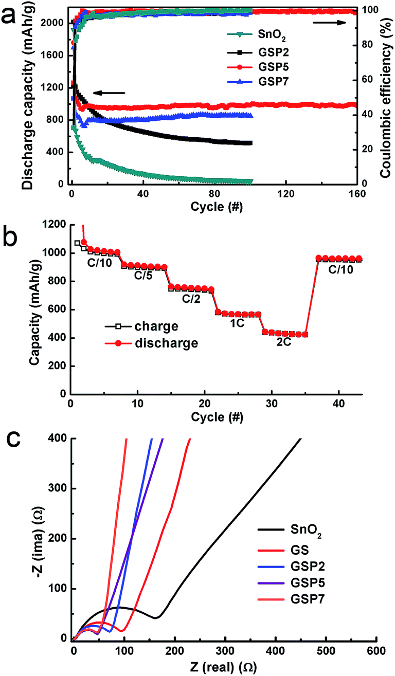 | ||
| Fig. 5 (a) Galvanostatic cycle performance plots of SnO2 and its ternary composites at 0.1 C in the potential range of 0.005–3.0 V vs. Li/Li+. (b) Rate performance of the composite GSP5. (c) EIS plots of SnO2, GS and GSP5. | ||
Fig. S3† further shows the discharge capacities of the composite SP5 or simply SP. The initial discharge capacities of the composites GSP2, GSP5, and GSP7 are respectively, 2015, 1759, and 1699 mA h g−1, whereas the charge capacities are 1145, 1029, and 839 mA h g−1, respectively. The coulombic efficiency values of the GSP2, GSP5, and GSP7 composites are 49.9, 58.5 and 49.4%, respectively. Low values of the coulombic efficiencies of first cycles may be due to the irreversible conversion of SnO2 to Sn and Li2O and the formation of SEI on the surface of the active material.40 The charge–discharge data of GS and SP5 are provided in the ESI.† Comparison of charge–discharge characteristics of all samples clearly demonstrate that the ternary composites, especially those with a high concentration of PEDOT:PSS (>2 wt%), show stable capacity from ∼10 cycles. This was further proved by the charge–discharge characteristics of GSP10 displayed in Fig. S4,† which shows stable capacity from the 10th cycle. The GSP10 composite exhibits a specific capacity of 709 mA h g−1 after 229 cycles with a coulombic efficiency >99%. It is notable that the specific capacity of the ternary composites increases first, then decreases with increasing amounts of PEDOT:PSS. The initial capacity loss in these electrodes is mainly due to the formation of SEI. Note that the capacity values were calculated on the basis of the total mass of each electrode. It is obvious that all the composites exhibit higher capacity than pure SnO2, and the ternary composites display even better capacity than the binary composites of GS or SP.
Notably, the composite GS is better in retaining the capacity compared to the composite SP. The severe capacity fading in SnO2, GS, and SP may be attributed to the pulverization of the electrodes. However, addition of PEDOT:PSS in GS increases the capacity of the ternary composites first and then decreases the capacity depending on the concentration of PEDOT:PSS. Capacity fading took place even with composite GSP2, which was not as severe as that with SnO2, GS and SP. The discharge capacity of GSP2 after 100 cycles was 515 mA h g−1. On the other hand, composites GSP5 and GSP7 show stable capacity from about 10 cycles. Therefore, we can conclude that the rGO together with PEDOT:PSS efficiently accommodate the volume change of SnO2 during the charge–discharge process, leading to stable capacity. The composite GSP5 shows a reversible capacity of about 974 mA h g−1 after 160 charge–discharge cycles with a coulombic efficiency over 99%, indicating that a highly reversible capacity of 1185 mA h g−1 can be achieved for SnO2 in the composite. This capacity is almost greater than by a factor of three than the commercial graphite anode, which shows a reversible capacity of 372 mA h g−1. Moreover, it is somehow close to the reversible capacity of 1494 mA h g−1 for nano-sized SnO2. On the other hand, GSP7 shows a discharge capacity of 851 mA h g−1 after 100 cycles, with a coulombic efficiency ∼99%. Good rate performance is essential for Li ion batteries. The rate performance of the composite is depicted in Fig. 5b, which shows that the composite exhibits excellent rate performance at different current densities. Even at high current densities of 1 C and 2 C, the composite delivers specific capacity values of 566 and 424 mA h g−1 at the seventh cycle, respectively. Moreover, the specific capacity can recover to 962 mA h g−1 when the current density returned to C/10.
Electrochemical impedance spectra (EIS) data for SnO2, SP, GSP2, GSP5, and GSP7 were collected and are shown in Fig. 5c. The EIS plots show semi-circles in the high frequency region and sloping straight lines at low frequencies. From these plots, it is clear that the ternary composites GSP5 and GSP7 show minimum charge-transfer resistance, which is due to the presence of highly conducting rGO and intimate contact of SnO2 nanoparticles with rGO and the conducting polymer PEDOT:PSS. Although their impedance values differ marginally, the composite of GSP5 displays more capacity than GSP7. It is notable that the impedance values of all the ternary composites are lower than that of GS due to the inclusion of PEDOT:PSS. Due to this reason together with insufficient cushioning to volume change, GS shows continuous capacity fading. On the other hand, SnO2 shows the highest charge-transfer resistance. From the above mentioned discussion, we can conclude that the high specific capacity of the composite GSP5 is obtained due to the following three aspects: (i) the ultra-small size of SnO2 nanoparticles, which decreases the lithium diffusion length in the composite matrix and partially accommodates volume change during charge–discharge cycling, eventually leading to the increased specific capacity, (ii) the highly conducting medium offered by rGO and PEDOT:PSS provides low charge-transfer resistance, and (iii) efficient buffering capability against volume change offered by the inclusion of rGO and PEDOT:PSS.
Conclusions
Ternary composites of SnO2 with reduced graphene oxide and PEDOT:PSS were synthesized through a one-pot wet chemical process under mild experimental conditions. In the composites, SnO2 nanoparticles are in the size range of 2–3 nm, and rGO acted as the conducting medium and buffering matrix to accommodate the volume change. In addition, PEDOT:PSS further contributed to buffer the volume change and increase the conductivity, though the increased addition of PEDOT:PSS could decrease the composite's conductivity. The composites showed higher lithium storage capability than pure SnO2 or the binary composites GS and SP. Moreover, they showed a remarkable coulombic efficiency >99%. This was possibly due to the efficient accommodation of the severe volume change of SnO2 by the PEDOT:PSS coating besides the incorporation of rGO. Apart from this, the ultra-small SnO2 nanoparticles decreased the lithium diffusion length in the composite, leading to high specific capacity. Employing only the rGO or PEDOT:PSS is not sufficient to alleviate the volume change of SnO2 during charge–discharge cycles. As a result, specific capacities of the ternary composites first increased with the amount of PEDOT:PSS and then decreased. The best capacity was shown by the composite containing 5 wt% PEDOT:PSS, which exhibited a specific capacity of 980 mA h g−1, equivalent to 1185 mA h g−1 with respect to the case of SnO2 only, after 160 cycles at a current density of 0.1 C. Moreover, it showed stable capacity at high current densities. We anticipate that the presented approach utilizing ternary composite system can replace commercial graphite anodes in lithium ion battery applications.Acknowledgements
This work was supported by research grants of NRF (2012M1A2A2671795, 2010-C1AAA001-2010-0029065), Global Frontier R&D Program on Center for Multiscale Energy System (2012M3A6A7055540), funded by the National Research Foundation under the Ministry of Science, ICT & Future, Korea. This work was also supported by Fundamental R&D Program for Technology of World Premier Materials funded by the Ministry of Trade, Industry & Energy of Korea.Notes and references
- S. R. Gowda, V. Pushparaj, S. Herle, G. Girishkumar, J. G. Gordon, H. Gullapalli, X. Zhan, P. M. Ajayan and A. L. M. Reddy, Nano Lett., 2012, 12, 6060–6065 CrossRef CAS PubMed.
- a. R. Park, J. S. Kim, K. S. Kim, K. Zhang, J. Park, J. H. Park, J. K. Lee and P. J. Yoo, ACS Appl. Mater. Interfaces, 2014, 6, 1702–1708 CAS.
- D. Deng, M. G. Kim, J. Y. Lee and J. Cho, Energy Environ. Sci., 2009, 2, 818 CAS.
- D. Wang, J. Yang, X. Li, D. Geng, R. Li, M. Cai, T.-K. Sham and X. Sun, Energy Environ. Sci., 2013, 6, 2900 CAS.
- H. Ghassemi, M. Au, N. Chen, P. A. Heiden and R. S. Yassar, ACS Nano, 2011, 5, 7805–7811 CrossRef CAS PubMed.
- H. Li, C. Lu and B. Zhang, Electrochim. Acta, 2014, 120, 96–101 CrossRef CAS PubMed.
- B. Wang, X. Li, X. Zhang, B. Luo, Y. Zhang and L. Zhi, Adv. Mater., 2013, 25, 3560–3565 CrossRef CAS PubMed.
- R. Yi, F. Dai, M. L. Gordin, S. Chen and D. Wang, Adv. Energy Mater., 2013, 3, 295–300 CrossRef CAS.
- M. Wu, J. E. C. Sabisch, X. Song, A. M. Minor, V. S. Battaglia and G. Liu, Nano Lett., 2013, 13, 5397–5402 CrossRef CAS PubMed.
- H. Lee, H. Kim, S.-G. Doo and J. Cho, J. Electrochem. Soc., 2007, 154, A343 CrossRef CAS PubMed.
- W. Li, J. Zheng, T. Chen, T. Wang, X. Wang and X. Li, Chem. Commun., 2014, 50, 2052–2054 RSC.
- G. H. Yue, X. Q. Zhang, Y. C. Zhao, Q. S. Xie, X. X. Zhang and D. L. Peng, RSC Adv., 2014, 4, 21450 RSC.
- H. Kim, Y. Son, C. Park, J. Cho and H. C. Choi, Angew. Chem., Int. Ed., 2013, 52, 5997–6001 CrossRef CAS PubMed.
- H. Lee, M. G. Kim, C. H. Choi, Y.-K. Sun, C. S. Yoon and J. Cho, J. Phys. Chem. B, 2005, 109, 20719–20723 CrossRef CAS PubMed.
- Y. Liu, S. Zhang and T. Zhu, ChemElectroChem, 2014, 1, 706–713 CrossRef CAS.
- E. G. Bae, Y.-H. Hwang and M. Pyo, Bull. Korean Chem. Soc., 2013, 34, 1199–1204 CrossRef CAS.
- X. Hou, H. Jiang, Y. Hu, Y. Li, J. Huo and C. Li, ACS Appl. Mater. Interfaces, 2013, 5, 6672–6677 CAS.
- S. Baek, S.-H. Yu, S.-K. Park, A. Pucci, C. Marichy, D.-C. Lee, Y.-E. Sung, Y. Piao and N. Pinna, RSC Adv., 2011, 1, 1687 RSC.
- C.-M. Chen, Q. Zhang, J.-Q. Huang, W. Zhang, X.-C. Zhao, C.-H. Huang, F. Wei, Y.-G. Yang, M.-Z. Wang and D. S. Su, J. Mater. Chem., 2012, 22, 13947 RSC.
- S. Chen, M. Wang, J. Ye, J. Cai, Y. Ma, H. Zhou and L. Qi, Nano Res., 2013, 6, 243–252 CrossRef CAS PubMed.
- X.-T. Chen, K.-X. Wang, Y.-B. Zhai, H.-J. Zhang, X.-Y. Wu, X. Wei and J.-S. Chen, Dalton Trans., 2014, 43, 3137–3143 RSC.
- Z. Chen, M. Zhou, Y. Cao, X. Ai, H. Yang and J. Liu, Adv. Energy Mater., 2012, 2, 95–102 CrossRef CAS.
- Y.-L. Ding, Y. Wen, P. a. van Aken, J. Maier and Y. Yu, Nanoscale, 2014, 6, 11411–11418 RSC.
- Q. Guo and X. Qin, ECS Solid State Lett., 2013, 2, M41–M43 CrossRef CAS PubMed.
- F. Han, W.-C. Li, M.-R. Li and A.-H. Lu, J. Mater. Chem., 2012, 22, 9645 RSC.
- X. Huang, X. Zhou, L. Zhou, K. Qian, Y. Wang, Z. Liu and C. Yu, ChemPhysChem, 2011, 12, 278–281 CrossRef CAS PubMed.
- Q. Guo, Z. Zheng, H. Gao, J. Ma and X. Qin, J. Power Sources, 2013, 240, 149–154 CrossRef CAS PubMed.
- H. Kim, S.-W. Kim, Y.-U. Park, H. Gwon, D.-H. Seo, Y. Kim and K. Kang, Nano Res., 2010, 3, 813–821 CrossRef CAS PubMed.
- J. G. Kim, S. H. Nam, S. H. Lee, S. M. Choi and W. B. Kim, ACS Appl. Mater. Interfaces, 2011, 3, 828–835 CAS.
- K. Kisu, M. Iijima, E. Iwama, M. Saito, Y. Orikasa, W. Naoi and K. Naoi, J. Mater. Chem. A, 2014, 2, 13058 CAS.
- J. Li, Y. Zhao, N. Wang and L. Guan, Chem. Commun., 2011, 47, 5238–5240 RSC.
- Y.-D. Ko, J.-G. Kang, J.-G. Park, S. Lee and D.-W. Kim, Nanotechnology, 2009, 20, 455701 CrossRef PubMed.
- F. Li, J. Song, H. Yang, S. Gan, Q. Zhang, D. Han, A. Ivaska and L. Niu, Nanotechnology, 2009, 20, 455602 CrossRef PubMed.
- P. Lian, J. Wang, D. Cai, L. Ding, Q. Jia and H. Wang, Electrochim. Acta, 2014, 116, 103–110 CrossRef CAS PubMed.
- J. Lin, Z. Peng, C. Xiang, G. Ruan, Z. Yan, D. Natelson and J. M. Tour, ACS Nano, 2013, 7, 6001–6006 CrossRef CAS PubMed.
- J. Liang, W. Wei, D. Zhong, Q. Yang, L. Li and L. Guo, ACS Appl. Mater. Interfaces, 2012, 4, 454–459 CAS.
- J. Liang, Y. Zhao, L. Guo and L. Li, ACS Appl. Mater. Interfaces, 2012, 4, 5742–5748 CAS.
- Y.-M. Lin, R. K. Nagarale, K. C. Klavetter, A. Heller and C. B. Mullins, J. Mater. Chem., 2012, 22, 11134 RSC.
- G. Liu, H. Wang, B. Jin, Z. Yang, W. Qi, Y. Liu and Q. Jiang, Int. J. Electrochem. Sci., 2013, 8, 4797–4806 CAS.
- S. J. R. Prabakar, Y.-H. Hwang, E.-G. Bae, S. Shim, D. Kim, M. S. Lah, K.-S. Sohn and M. Pyo, Adv. Mater., 2013, 25, 3307–3312 CrossRef CAS PubMed.
- X. Wang, X. Cao, L. Bourgeois, H. Guan, S. Chen, Y. Zhong, D.-M. Tang, H. Li, T. Zhai, L. Li, Y. Bando and D. Golberg, Adv. Funct. Mater., 2012, 22, 2682–2690 CrossRef CAS.
- A. Bhaskar, M. Deepa, M. Ramakrishna and T. N. Rao, J. Phys. Chem. C, 2014, 118, 7296–7306 CAS.
- M. S. A. Sher Shah, A. R. Park, K. Zhang, J. H. Park and P. J. Yoo, ACS Appl. Mater. Interfaces, 2012, 4, 3893–3901 CAS.
- M. S. A. Sher Shah, K. Zhang, a. R. Park, K. S. Kim, N.-G. Park, J. H. Park and P. J. Yoo, Nanoscale, 2013, 5, 5093–5101 RSC.
- X. Zhou, L.-J. Wan and Y.-G. Guo, Adv. Mater., 2013, 25, 2152–2157 CrossRef CAS PubMed.
- H. Seema, K. Christian Kemp, V. Chandra and K. S. Kim, Nanotechnology, 2012, 23, 355705 CrossRef PubMed.
- A. a. Farah, S. a. Rutledge, A. Schaarschmidt, R. Lai, J. P. Freedman and A. S. Helmy, J. Appl. Phys., 2012, 112, 113709 CrossRef PubMed.
- M. S. A. Sher Shah, W.-J. Kim, J. Park, D. K. Rhee, I.-H. Jang, N.-G. Park, J. Y. Lee and P. J. Yoo, ACS Appl. Mater. Interfaces, 2014, 6, 20819–20827 CAS.
- W. Zhang, B. Zhao, Z. He, X. Zhao, H. Wang, S. Yang, H. Wu and Y. Cao, Energy Environ. Sci., 2013, 6, 1956 CAS.
- S. Paek, E. Yoo and I. Honma, Nano Lett., 2009, 9, 72–75 CrossRef CAS PubMed.
- R. Demir-Cakan, Y. Hu, M. Antonietti, J. Maier and M. Titirici, Chem. Mater., 2008, 20, 1227–1229 CrossRef CAS.
- S. Yang, W. Yue, J. Zhu, Y. Ren and X. Yang, Adv. Funct. Mater., 2013, 23, 3570–3576 CrossRef CAS.
- Y. Jiang, T. Yuan, W. Sun and M. Yan, ACS Appl. Mater. Interfaces, 2012, 4, 6216–6220 CAS.
- P. Lian, X. Zhu, S. Liang, Z. Li, W. Yang and H. Wang, Electrochim. Acta, 2011, 56, 4532–4539 CrossRef CAS PubMed.
- H. Kim, G. O. Park, Y. Kim, S. Muhammad, J. Yoo, M. Balasubramanian, Y. Cho, M.-G. Kim, B. Lee, K. Kang, H. Kim, J. M. Kim and W. Yoon, Chem. Mater., 2014, 26, 6361–6370 CrossRef CAS.
- Y. Tang, D. Wu, S. Chen, F. Zhang, J. Jia and X. Feng, Energy Environ. Sci., 2013, 6, 2447 CAS.
- X. Jiang, X. Yang, Y. Zhu, K. Fan, P. Zhao and C. Li, New J. Chem., 2013, 37, 3671 RSC.
Footnotes |
| † Electronic supplementary information (ESI) available: Survey XPS spectrum and thermo gravimetric analysis are shown in Fig. S1 and S2, respectively. Fig. S3 depicts cycle performance of GS and SP5. On the other hand, charge–discharge performance and coulombic efficiency of GSP10 is displayed in Fig. S4. See DOI: 10.1039/c4ra15913f |
| ‡ The authors contributed equally to this work. |
| This journal is © The Royal Society of Chemistry 2015 |