Photo-assisted high performance single atom electrocatalysis of the N2 reduction reaction by a Mo-embedded covalent organic framework†
Juan
Wang
a,
Zhihua
Zhang
a,
Siyun
Qi
a,
Yingcai
Fan
 a,
Yanmei
Yang
 b,
Weifeng
Li
 *a and
Mingwen
Zhao
 *a
*a
aSchool of Physics & State Key Laboratory of Crystal Materials, Shandong University, Jinan 250100, Shandong, China. E-mail: lwf@sdu.edu.cn; zmw@sdu.edu.cn
bCollege of Chemistry, Chemical Engineering and Materials Science, Collaborative Innovation Center of Functionalized Probes for Chemical Imaging in Universities of Shandong, Key Laboratory of Molecular and Nano Probes, Ministry of Education, Shandong Normal University, Jinan, 250014, China
First published on 23rd June 2021
Abstract
The development of highly efficient, low cost and environment-friendly solutions for the conversion of nitrogen gas to ammonia under ambient conditions has great industrial and academic significance. Single-atom catalysis (SAC) is recognized to have high potential in this area due to its rich chemical and physical properties. In this work, we proposed a Mo atom anchored covalent organic framework (MoPc-TFPN) for photo-assisted electrocatalysis of the N2 reduction reaction using first-principles calculations. Our theoretical results demonstrated that this MoPc-TFPN catalyst has a considerably low onset potential of −0.24 V, which is comparable to or better than those of widely used noble catalysts. Because Mo denotes electrons to the Pc-TFPN substrate, the positive charged Mo has low binding affinity to H, thus greatly suppressing the competing hydrogen evolution reaction (HER). More importantly, the MoPc-TFPN has appropriate band edges with high light-absorption efficiency, which could be beneficial to improve the electrocatalytic efficiency of the NRR. This work uncovers a promising strategy for nitrogen fixation by photo-enhanced electrocatalysis under ambient conditions which could combine the ultimate functions of 2D semiconducting nanostructures for high performance catalysis.
1. Introduction
The conversion of gaseous nitrogen (N2) to ammonia (NH3) has high industrial significance.1 However, the strong inertness of the N![[triple bond, length as m-dash]](https://www.rsc.org/images/entities/char_e002.gif) N bond makes the NH3 production technically difficult.2 Nowadays, the industrial NH3 production mainly follows the traditional Haber–Bosch process. Using Fe- or Mo-based catalysts, N2 and hydrogen (H2) were circulated over the catalyst at a temperature of about 500 °C at a high pressure (150–350 atm) to produce NH3.3–5 The industrial-scale production of NH3 faces the drawbacks of high energy consumption and low conversion rate. The development of economic and environment-friendly strategies to overcome these drawbacks of the Haber–Bosch method is highly desirable. In the biogeochemical nitrogen cycle, nitrogen fixation is catalyzed by an enzyme complex, nitrogenase, accounting for over 60% of the total atmospheric N2 fixed.6,7 Inspired by biological nitrogen fixation, heterogeneous catalysts through multiple proton and electron transfer steps for low energy consumption and zero CO2 emission were proposed and have demonstrated big success.8,9
N bond makes the NH3 production technically difficult.2 Nowadays, the industrial NH3 production mainly follows the traditional Haber–Bosch process. Using Fe- or Mo-based catalysts, N2 and hydrogen (H2) were circulated over the catalyst at a temperature of about 500 °C at a high pressure (150–350 atm) to produce NH3.3–5 The industrial-scale production of NH3 faces the drawbacks of high energy consumption and low conversion rate. The development of economic and environment-friendly strategies to overcome these drawbacks of the Haber–Bosch method is highly desirable. In the biogeochemical nitrogen cycle, nitrogen fixation is catalyzed by an enzyme complex, nitrogenase, accounting for over 60% of the total atmospheric N2 fixed.6,7 Inspired by biological nitrogen fixation, heterogeneous catalysts through multiple proton and electron transfer steps for low energy consumption and zero CO2 emission were proposed and have demonstrated big success.8,9
Currently, anchoring single-atom metals on the surface of 2D materials opened up a promising strategy to utilize the surface sites and improve the NRR process due to their high specific activity and maximum atom utilization. Furthermore, the positively charged metal atoms in SACs might be effective in suppressing the HER process by the coulombic interaction on the surface. SACs have been widely applied in a series of catalytic reactions,10,11e.g., hydrogen evolution reaction (HER),12 oxygen evolution reaction (OER),13 oxygen reduction reaction (ORR),14 NRR,15etc. Unfortunately, the high surface free energy of the anchored metal atoms results in migration and aggregation of active atoms during synthetic and catalytic processes, which leads to the rapid decay of catalytic activity.
With respect to SACs, two-dimensional covalent organic frameworks (2D-COFs) with porous configurations have drawn increasing interest, due to their high surface area, regular pore size, excellent electrical properties, tailorable structure and high stability.16,17 A promising strategy to address the problem of active TM atom aggregation is to deposit TMs in 2D COFs.18 Porous 2D COFs with modularly tunable structures assembled from metal cations and organic ligands hold great promise in gas sensors,19 magnetism,20 hyperbolic materials,21 photo/electrocatalysts,22,23 and so on. Especially, the porous configurations of 2D-COFs offer abundant sites to anchor TM atoms.24 The π–π conjugation in 2D COFs can not only inhibit the aggregation of TM atoms and facilitate electron transportation in chemical reactions but also facilitates chemical reactions.25 Very recently, Lan and co-workers reported the successful synthesis of dioxin-linked metallophthalocyanine covalent organic frameworks (MPc-TFPN COF) where the M represents Ni, Co or Zn.26 Benefitting from the rich electrons of M atoms and efficient light absorption, electrocatalytic CO2 reduction (ECR) was realized by the MPc-TFPN COF with remarkably high activity, stability and selectivity.
Numerous theoretical studies have highlighted the high NRR activity of 2D materials when anchored with Mo atoms, such as BN,27 graphdiyne,28 C9N4 (ref. 29) and 2D-COFs,30,31 suggesting a promising strategy for the development of Mo-based NRR catalysts. Yang and co-workers have predicted the NRR performance of Mo atoms anchored on the BM-β12 monolayer with an onset potential of −0.26 V.32 Motivated by the above reports, we anticipate that isolated Mo atoms anchored on the MPc-TFPN monolayer (MoPc-TFPN) would be a promising electrocatalyst for N2 fixation in this work. In contrast to the easy-aggregation of Mo on the surface of graphene,33 TM–N4 can anchor stably on the MPc-TFPN and distribute evenly. Through first-principles calculations, we demonstrated that the MoPc-TFPN displays the highest NRR catalytic activity compared to all architectures reported before. The NRR onset potential is as low as 0.24 V, which is even lower than that of noble catalysts and COF-based catalysts. Our results also reveal that MoPc-TFPN has highly efficient optical absorption and large optical voltage which are the key features to drive the NRR process. In addition, the adsorption and activation of N2 on MoPc-TFPN can be explained from the perspective of valence bond theory. This study provides a new and efficient approach for NRR photo-/electrocatalysts which could stimulate future experimental studies in this area.
2. Methods and computational details
Spin-polarized first-principles calculations were carried out on the basis of density functional theory (DFT) implemented in the Vienna ab initio simulation package (VASP) code to investigate the NRR on the MoPc-TFPN.34,35 The electron–electron interaction was treated by the Perdew–Burke–Ernzerhof (PBE) style within the generalized gradient approximation (GGA).36 Considering the porous configuration of the MoPc-TFPN, the van der Waals interaction was involved using the empirical correction in the Grimme's scheme (DFT-D3).37 The projected augmented wave (PAW) potential38 was utilized to describe the ion–electron interaction and the energy cutoff employed for plane-wave expansion of electron wave function in real space was set to 500 eV. The iterative convergences of energy and force were 10−5 eV and 0.01 eV Å−1, respectively. An extra about 20 Å vacuum region was inserted along the z-direction to avoid mutual interaction between two periodic units. The Brillouin zone was sampled by a 3 × 3 × 1 k-point grid for electronic property calculation, whereas only the Γ point was considered in structural optimization. This k-point strategy has been verified to give sufficient accuracy. The HSE06 hybrid functional was utilized to calculate the electronic band structure and optical absorption spectrum. The thermal stability of the 2D MoPc-TFPN surface was studied by Ab initio Molecular Dynamics (AIMD) calculations at 800 K for 5000 fs. In addition, visualization analysis of charge density difference was performed by the VESTA code.39 Taking into account that the NRR is conducted in aqueous electrolytes, the effects of aqueous solution were calculated with the implicit solvation model.40The calculations of Gibbs free-energy change (ΔG) for each elemental step were based on the computational hydrogen electrode model proposed by Nørskov et al.,41 which can be computed by
| ΔG = ΔE + ΔEZPE − TΔS − ΔGU + ΔGpH |
![[thin space (1/6-em)]](https://www.rsc.org/images/entities/char_2009.gif) 10 × pH is the correction of the free energy for H+, where kB is the Boltzmann constant. In our calculations, we took T = 298.15 K, U = 0 V and pH = 0. The detailed energetic characteristics for reaction intermediates are summarized in Tables S1 and S2 in the ESI.†
10 × pH is the correction of the free energy for H+, where kB is the Boltzmann constant. In our calculations, we took T = 298.15 K, U = 0 V and pH = 0. The detailed energetic characteristics for reaction intermediates are summarized in Tables S1 and S2 in the ESI.†
3. Results and discussion
3.1. Structure and stability of MoPc-TFPN
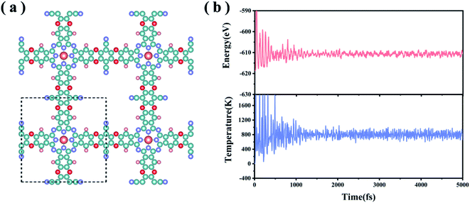
In experiments, the MPc-TFPN COF (M = Ni, Co, Zn) monolayers were synthesized by condensing 2,3,9,10,16,17,23,24-octahydroxyphthalocyaninato metal (MPc-8OH) with tetrafluorophthalonitrile (TFPN) to form three dioxin-linked phthalocyanine COFs26 as shown in Fig. 1(a). The TM atoms are embedded in the framework by forming TM–N4 units. In this work, we considered a specific MoPc-TFPN COF with Mo doping. To evaluate the structural stability, we defined the binding strength (Eb) between Mo and the Pc-TFPN framework as Eb = EMoPc-TFPN − EMo − EPc-TFPN, with EMoPc-TFPN, EMo and EPc-TFPN depicting the energies of MoPc-TFPN, single Mo atoms and Pc-TFPN, respectively. After full structural optimization, it is found that the Mo atoms are firmly anchored onto the Pc-TFPN with Eb of −9.72 eV per Mo. For comparison, we also calculated the cohesive energy (Ecoh) of the Mo metal using the definition: Ecoh = (Ebulk − n × EMo)/n, where Ebulk represents the energy of the Mo crystal and n is the number of Mo atoms in the crystal. Using the same theoretical level of Eb, the Ecoh of Mo is determined to be −6.89 eV per Mo, which is obviously higher than Eb. This implies that the interaction between Mo and Pc-TFPN is strong enough to avoid the self-aggregation of the anchored Mo atoms. By Bader charge analysis, about 1.47 electrons are transferred from each Mo atom to the Pc-TFPN COF, revealing the strong coupling of Mo to Pc-TFPN, which is conducive to enhancing Mo–N4 bonds, thereby confirming the glorious structural stability of the MoPc-TFPN COF catalyst. To further verify the thermodynamic stability of MoPc-TFPN, Ab initio molecular dynamics simulations (AIMD) were conducted at a high temperature of 800 K for 5 ps with a time step of 1 fs, during which the total energy was monitored. As demonstrated in Fig. 1(b), the total energy quickly reached the equilibrium of −612 eV in about 1 ps and remained constant in the last simulations. Considerably small fluctuations are observed which is a direct indication of the high thermodynamic stability of MoPc-TFPN.3.2. Chemisorption and activation of N2
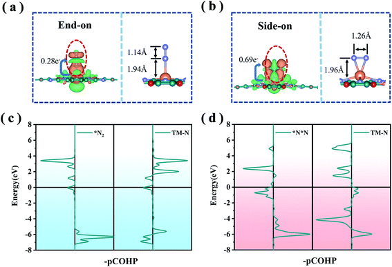
The first step of the NRR reaction is the chemisorption and activation of N2 on the electrocatalyst. From our preliminary calculations, the ground state of MoPc-TFPN is spin-polarized and the spin is highly localized at the Mo atom with a magnetic moment of about 4 μB, which plays a vital role in N2 activation. In addition, Bader charge analysis shows that 1.47 electrons are transferred from each Mo atom to the Pc-TFPN substrate, making the Mo atom highly positively charged and an ideal activation site for N2 capture and activation. After structural optimization, two stable binding orientations were detected for the N2 on the MoPc-TFPN surface which are denoted as end-on and side-on configurations as depicted in Fig. 2. The lengths of the Mo–N bonds for the end-on and side-on patterns are 1.94 and 1.96 Å, respectively. The free energies of N2 adsorption are −0.55 eV (end-on) and −0.01 eV (side-on), indicating that the chemisorption of nitrogen is a spontaneous process from the gaseous N2, especially for the end-on pattern. Significant charge transfer was observed between the anchored Mo atom and N2 for both adsorption configurations. In detail, there are 0.28 and 0.64 electrons transferred to MoPc-TFPN for the end-on and side-on modes. This difference can be attributed to the higher amount of back-donation taking place in the side-on the than the end-on mode.42 The charge redistribution can be visualized by the charge accumulation and depletion displayed by the orange and green region in Fig. 2(a) and (b), where the electron transfer in the side-on case is more obvious than the end-on case. Moreover, the stability of adsorbed N2 is correlated with the occupancy of antibonding orbitals, as shown in Fig. 2(c). The antibonding orbitals of the side-on model are closer to the EF compared with that of end-on, implying that the transferred electrons occupy the antibonding orbitals in the side-on mode. Furthermore, the integrated crystal orbital Hamilton population (ICOHP) values of the N![[triple bond, length as m-dash]](https://www.rsc.org/images/entities/char_e002.gif) N bond in the *N2 intermediate are −7.05 and −3.19 for the end-on and side-on configurations, respectively.43,44 All these results indicate that the end-on mode is energetically more favorable than the side-on binding mode.
N bond in the *N2 intermediate are −7.05 and −3.19 for the end-on and side-on configurations, respectively.43,44 All these results indicate that the end-on mode is energetically more favorable than the side-on binding mode.
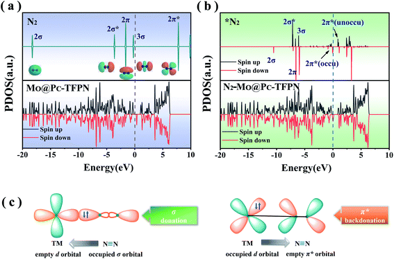
The reaction of the N2 adsorbate with the exposed Mo atom follows the “acceptance–donation” mechanism.45 More specifically, as depicted in Fig. 3(c), the Mo atom at the center possessing the empty d orbital can “accept” the lone-pair electrons from the N2 to strengthen the Mo–N bond, and meanwhile “donate” electrons to the antibonding orbitals of N2 to weaken the N![[triple bond, length as m-dash]](https://www.rsc.org/images/entities/char_e002.gif) N bond. To verify the essential orbitals in the NRR reaction, each orbital of gaseous N2 near the Fermi level (EF), i.e., 2σ, 2σ*, 2π, 3σ and 2π*, and the 3σ orbital is summarized in Fig. 3(a) which is represented as the partial density of states (PDOS). The unoccupied d orbitals of the Mo atom on the MoPc-TFPN accept electrons from the 2π and 3σ molecular orbitals of N2, forming the bonding states to strengthen the N2 adsorption and becoming metallic. Good electrical conductivity is the essential factor to improve the electrocatalytic performance of the NRR. Meanwhile, the occupied d orbitals donate electrons to the 2π* orbital of N2, as shown by partial density of states (PDOS) in Fig. 3(a) and (b). Therefore, these electronic features make MoPc-TFPN a promising catalyst for the conversion of N2 to NH3.
N bond. To verify the essential orbitals in the NRR reaction, each orbital of gaseous N2 near the Fermi level (EF), i.e., 2σ, 2σ*, 2π, 3σ and 2π*, and the 3σ orbital is summarized in Fig. 3(a) which is represented as the partial density of states (PDOS). The unoccupied d orbitals of the Mo atom on the MoPc-TFPN accept electrons from the 2π and 3σ molecular orbitals of N2, forming the bonding states to strengthen the N2 adsorption and becoming metallic. Good electrical conductivity is the essential factor to improve the electrocatalytic performance of the NRR. Meanwhile, the occupied d orbitals donate electrons to the 2π* orbital of N2, as shown by partial density of states (PDOS) in Fig. 3(a) and (b). Therefore, these electronic features make MoPc-TFPN a promising catalyst for the conversion of N2 to NH3.
3.3. Reaction pathway and free energy profile
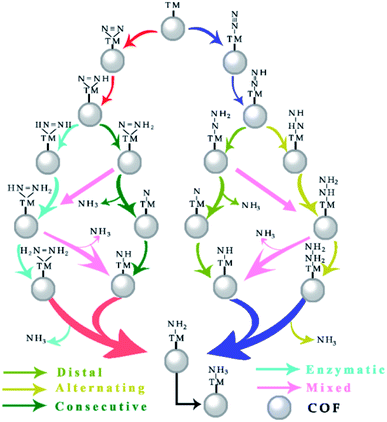
As depicted in Fig. 4, the electrocatalytic nitrogen-to-ammonia conversion is a complicating process which includes two different N2 adsorption configurations (end-on and side-on modes as shown in Fig. 2), four possible reaction pathways (distal, alternating, consecutive and enzymatic routes) and six proton/electron pair (H+/e−) reduction steps. In the following, we discuss these reaction pathways and the corresponding profiles of free energy ΔG. The model structures with top and side views of the whole process are shown in Fig. S1–S4 in the ESI.†We firstly assessed the distal pathway and calculated the reaction energy profile shown in Fig. 5(a). For the first hydrogenation step (*N2 + *H → *N2H), it is uphill by 0.24 eV due to the weak adsorption of N2H* species. Subsequently, the third proton/electron pairs attack the distal N atom of *N2H2, breaking the N–N bond to release the first NH3 molecule. The remaining *N is then hydrogenated to form *NH, *NH2 and *NH3 by successively adsorbing three proton/electron pairs. The hydrogenation of *N2 to *N2H has a Gibbs free energy barrier of only 0.24 eV. This value of hydrogenation is significantly lower than those of most of the TM-based SACs for the NRR reported so far and this hydrogenation reaction has been believed to be the potential-determining step (PDS).46–48
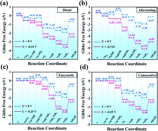 | ||
| Fig. 5 Gibbs free energy diagrams for the NRR on MoPc-TFPN through (a) distal, (b) alternating, (c) enzymatic and (d) consecutive pathways in water solvent. | ||
Additionally, we also investigated the alternating pathway (Fig. 5(b)). It is worth mentioning that the first two steps in the NRR are identical for the distal and the alternating pathways, i.e., N2 → *N2 and *N2 + *H → *N2H. The protonation step of *N2H + *H → *NHNH has the maximum change of Gibbs free energy of 0.72 eV. Subsequently, proton/electron pairs consecutively attack the N atoms to form *NHNH2 and *NH2NH2 species, and meanwhile the N![[triple bond, length as m-dash]](https://www.rsc.org/images/entities/char_e002.gif) N bond is elongated but does not break, initiating the N2 activation. Compared with the alternating mechanism, the NRR by the MoPc-TFPN monolayer via the distal mechanism is energetically favorable for the protonation steps of *N2H + *H → *N2H2 and *N2H2 + *H → *N + NH3(g) as the free energies are calculated to be −0.26 and −1.38 eV, respectively. In the last step, the two nitrogen atoms are hydrogenated sequentially, releasing two ammonia molecules.
N bond is elongated but does not break, initiating the N2 activation. Compared with the alternating mechanism, the NRR by the MoPc-TFPN monolayer via the distal mechanism is energetically favorable for the protonation steps of *N2H + *H → *N2H2 and *N2H2 + *H → *N + NH3(g) as the free energies are calculated to be −0.26 and −1.38 eV, respectively. In the last step, the two nitrogen atoms are hydrogenated sequentially, releasing two ammonia molecules.
For the enzymatic pathway illustrated in Fig. 5(c), N2 atoms bind to the catalyst surface in a side-on binding mode. Generally, the trend of the energy profile in the enzymatic pathway is similar to that of the alternating pathway. The adsorbed N2 molecule is firstly hydrogenated by reaction with a (H+ + e−) pair to produce *N*NH. After a series of hydrogenation steps, the *N*NH is successively reduced to *NH*NH, *NH*NH2, *NH2*NH2 and *NH2 + NH3(g), with the corresponding values of ΔG being 0.42, 0.09, −0.67 and −1.90 eV, respectively. The free energy change in the first hydrogenation step (*N2 + *H → *N*NH) is superior to the alternating pathway with a considerably small PDS of 0.25 V. However, from the perspective of the minimum energy principle, the enzymatic pathway is energetically unfavorable because nitrogen adsorption is more stable in end-on mode.
Finally, for the consecutive pathway in Fig. 5(d), the PDS is the hydrogenation of *N*N into *N*NH with a low free energy of 0.25 eV, which is endothermic while all the others are exothermic. The general trend of the energy profile in the last four steps (the formation and desorption of NH3) is similar to that in the distal pathway. The rate-determining step of the four reaction pathways is the first hydrogenation process with a negligible onset potential difference. From all the above results, the low over-potential endows MoPc-TFPN with a high potential to act as a highly efficient catalyst for N2 reduction into NH3 with low energy consumption. Based on the above PDS and energy analysis, it is found that the distal reaction pathway is the most favorable pathway with a considerably low onset potential of −0.24 V relative to the SHE, which is superior to other recently proposed efficient SACs, such as single Pt atom supported on g-C3N4,49 single-atom Fe implanted nitrogen-doped carbon catalysts (Fe1-N-C)50 and N-doped porous carbon.51 It is noteworthy that *NH3 → NH3(g) showed an uphill energy change independent of the applied potential with a NH3 desorption energy of 1.23 eV, which is disadvantageous for NH3 release. However, in the experiments, the ammonia does not exist in the form of gaseous ammonia, but as protonated NH4+ ions.52–54 It has also been proved that this step is actually not an obstacle because *NH3 is prone to protonation to form NH4+ in the acidic electrolyte (pH = 0).44,55 In addition, our predicted value (1.23 eV) is much lower than that of B@g-CN (2.23 eV)56 and Pt-SACs/CTF (1.40 eV)57 NRR catalysts. For comparison, the Pt-SACs/CTF nanosheets are experimentally reported to have excellent NRR photocatalytic performance and the potential of photogenerated electrons (−0.54 V) is sufficient to drive the NRR.57 Therefore, the desorption of NH3 from the MoPc-TFPN in the current study is expected to be not difficult.
Considering that the electrocatalytic NRR takes place in an aqueous environment,58 we considered the solvation effects in our calculations by VASPsol. It is found that the solvation has different contributions to the energetic features of the intermediate, where the onset potential was lowered by ∼0.1 eV. Additionally, because the NRR process involves complicated surface–adsorbate interactions, enthalpy correction to the Gibbs free energy should be included, which is about 0.03–0.11 eV, consistent with the previous report.47 The Gibbs free energy diagrams with and without the solvation and enthalpy corrections are summarized in Fig. S5.† It is seen that the Gibbs free energy change of the PDS for the distal NRR mechanism is reduced from 0.24 to 0.21 eV. Furthermore, the thermal corrections ∫CpdT for each individual adsorbed species on Mo-TFPN are also calculated and given in Table S2.† Notably, the above corrections not only substantially changed Gibbs free energies but also altered the identity of the PDS.
3.4. Origin of the high NRR activity
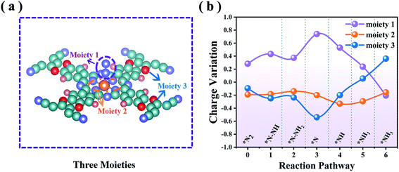
To probe the mechanistic origin of the high catalytic activity of MoPc-TFPN, for each hydrogenation step we analyzed the charge transfer between the reactants. For the whole NRR process, each intermediate can be divided into three moieties:56 NmHn (moiety 1), the MoN4 unit composed of a Mo atom with four surrounding N atoms (moiety 2) and the Pc-TFPN ligand without N4 (moiety 3), as illustrated in Fig. 6(a). From Fig. 6(b) and Table S3 in the ESI† we can see that the adsorbed NmHn can obtain electrons from the Pc-TFPN substrate during the N2 adsorption, the first hydrogenation step and the *N–NH3 formation. In the following, the redundant electrons of the NmHn transferred back to the substrate. Thus, the variations of the charges of moiety 1 and moiety 3 change in an opposite manner, while for the MoN4 unit moiety, it mainly acts as an intermediary of electrons to translocate between the Pc-TFPN and NmHn species in the subsequent four hydrogenation processes, although a constant net charge of ∼0.2 |e| is observed. As a consequence, efficient charge transfer to N2 is recognized to be one essential factor to the enhanced NRR catalyst.3.5. Selectivity of MoPc-TFPN for the NRR against HER
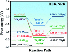
Ammonia selectivity against the hydrogen evolution reaction (HER) is another crucial criterion to evaluate the NRR catalytic performance, because the HER is considered to be a competing reaction to the NRR in acidic electrolytes.59 Poor selectivity to ammonia will cause excessive hydrogen adsorption on the active sites, causing deactivation of the catalyst and inhibiting the two reactions. On the other hand, from a kinetic point of view, the combination of protons and electrons will generate H2 instead of NH3. Therefore, in the NRR reaction, it is of great significance to suppress the competing HER process.Our calculations showed that the adsorption energy of a H atom on MoPc-TFPN is about −0.55 eV, which is considerably weaker than the binding of a N2 molecule on MoPc-TFPN (−0.82 eV). This implies that the N2 molecule has higher priority than H2 to bind with MoPc-TFPN, which suppresses the subsequent HER. The specific values of ΔGH and ΔGN2 for MoPc-TFPN are determined to be −0.26 and −0.55 eV when U = 0 vs. SHE. It will lead to preferential coverage of N2 molecules on the TM, instead of H. Moreover, the Gibbs free energy of H adsorption on the surface of MoPc-TFPN (|ΔGH| = 0.26 eV) is higher than the onset potential of the NRR (0.24 eV). Thus, when the electrode potential of −0.24 V is adopted, the NRR can proceed spontaneously along the distal pathway because the HER faces an energy barrier of about 0.02 eV as shown in Fig. 7. As a consequence, the MoPc-TFPN should exhibit a high NRR selectivity and suppressed HER. Additionally, the possible poisoning effects of H2O molecules on the MoPc-TFPN catalyst have also been explicitly considered in our calculations, where the binding energy of a H2O molecule on the Mo atom of MoPc-TFPN in the aqueous solution is only −0.36 eV, indicating that the presence of a H2O molecule will not poison the catalyst.30
3.6. Optical performance of MoPc-TFPN
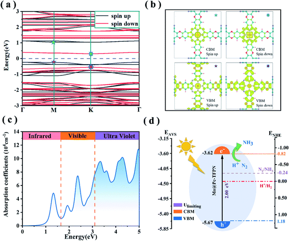
As revealed from experiments, light irradiation facilitates electrochemical activation of CO2 molecules over the phthalocyanine COF catalyst because the current density increases under light irradiation.26 Thus we anticipate that, for the phthalocyanine MoPc-TFPN under study, light irradiation can enhance the electron transfer to the adsorbed N2, thus benefitting the reduction of N2. The spin-polarized electron band structures of the MoPc-TFPN are presented in Fig. 8(a). It is seen that the 2D MoPc-TFPN monolayer is an indirect band gap semiconductor with the band gaps of 1.39 and 1.00 eV for the two spin channels. As the PBE function always underestimates the band gap of semiconductors, the HSE06 function was used to verify the polarized gaps which gave the band gaps of 2.00 and 1.39 eV for spin-up and spin-down respectively. The electron–hole interactions also regulate the optical properties. Especially, numerous studies pointed out that pristine COF polymers usually have a high exciton binding energy which severely hinders the charge hole separation.60,61Fig. 8(b) depicts the spatial distributions of the electrons and holes in MoPc-TFPN where electrons and holes are effectively separated. In detail, the valence band maximum (VBM, the holes) states are localized at the ligand of the MoPc-TFPN, while the conduction band minimum (CBM, the electrons) states are mainly located at the Mo and N atoms of the inner side.Light absorption ability is another key factor in the efficiency of photocatalysts.62–65 To initiate the photocatalytic N2 conversion to NH3, the photocatalyst should possess a strong capability to harvest solar light, especially the ultraviolet and visible regions. Considering this, we further calculated the light absorption spectrum of MoPc-TFPN from the complex dielectric function calculated at the DFT-HSE06 level. As shown in Fig. 8(c), the MoPc-TFPN exhibits remarkable absorption in the visible light region and extends to infrared light. Moreover, the energies of the first absorption peak agree well with the band gap of 1.35 eV from the HSE06 function, validating the accuracy of the theoretical strategy employed in this work.
For photofixation of nitrogen, the ideal catalysts should have suitable band edges that match the N2/NH3 potentials.57,66,67 Light irradiation can excite electrons from the VBM to the CBM which are further transferred to adsorbed N2. As shown in Fig. 8(c), the negative conduction band position CBM (−0.82 V vs. NHE) of MoPc-TFPN is higher than the initial potential of N2/NH3 (−0.24 V vs. NHE), while for the VBM, it is located below the H+/H2 potential for the spin up bands. These results indicate that MoPc-TFPN has the capability of light absorption which can assist N2 conversion under visible-light irradiation.53
Combining the three features of highly electron–hole separation, wide light absorption ranges and appropriate band edge positions, the MoPc-TFPN is theoretically predicted to have high solar conversion efficiency, which is believed to greatly assist the NRR reaction.
Besides MoPc-TFPN, we have also considered other 2D TMPc-TFPN COFs with TM = Sc–Zn, Ru, Rh, Pd, and Ag. Our calculations showed that, except Mo, these TMPc-TFPN COFs have either weak N2 adsorption capability with positive ΔGN2 or large ΔGN2H − ΔGN2 values (>0.74 eV), thus resulting in low NRR catalytic activity. Therefore, only MoPc-TFPN stands out from the 2D TMPc-TFPN COFs as a promising NRR electrocatalyst.
4. Conclusions
To summarize, through first principles theory calculations, we rationally designed 2D MoPc-TFPN single-atom catalysts which exhibited remarkably high catalytic activity and excellent selectivity for the N2 fixation and reduction reaction under ambient conditions. This catalyst has a considerably small onset potential of −0.24 V and follows the distal mechanism for the conversion of N2 to NH3. The onset potential is further reduced to −0.21 V when considering the enthalpy correction and solvation effect. The origin of the high NRR catalytic activity of MoPc-TFPN can be elucidated by the “acceptance–donation” mechanism. More importantly, the efficient electron–hole separation and appropriate band edges account for the high light-absorption of MoPc-TFPN, which could be beneficial to improve the electrocatalytic efficiency of the NRR by light irradiation. This work offers a rational design for advanced sustainable NH3 production and can potentiate 2D semiconducting nanostructures for highly efficient catalysis.Conflicts of interest
The authors declare no competing financial interest.Acknowledgements
This study is supported by the National Natural Science Foundation of China (no. 11774201), the Natural Science Foundation of Shandong Province (ZR2020JQ04), and the Taishan scholarship of Shandong Province.References
- Y. Wan, J. Xu and R. Lv, Mater. Today, 2019, 27, 69–90 CrossRef CAS
.
- C. J. M. van der Ham, M. T. M. Koper and D. G. H. Hetterscheid, Chem. Soc. Rev., 2014, 43, 5183–5191 RSC
.
- A. Banerjee, B. D. Yuhas, E. A. Margulies, Y. Zhang, Y. Shim, M. R. Wasielewski and M. G. Kanatzidis, J. Am. Chem. Soc., 2015, 137, 2030–2034 CrossRef CAS PubMed
.
- H. Li, J. Shang, Z. Ai and L. Zhang, J. Am. Chem. Soc., 2015, 137, 6393–6399 CrossRef CAS PubMed
.
- C. Ling, Y. Zhang, Q. Li, X. Bai, L. Shi and J. Wang, J. Am. Chem. Soc., 2019, 141, 18264–18270 CrossRef CAS PubMed
.
- D. E. Canfield, A. N. Glazer and P. G. Falkowski, Science, 2010, 330, 192–196 CrossRef CAS PubMed
.
- S. Sultana, S. Mansingh and K. M. Parida, J. Mater. Chem. A, 2019, 7, 9145–9153 RSC
.
- H. Liu, L. Wei, F. Liu, Z. Pei, J. Shi, Z.-j. Wang, D. He and Y. Chen, ACS Catal., 2019, 9, 5245–5267 CrossRef CAS
.
- Q. Li, Y. Guo, Y. Tian, W. Liu and K. Chu, J. Mater. Chem. A, 2020, 8, 16195–16202 RSC
.
- M. Khalid, P. A. Bhardwaj, A. M. B. Honorato and H. Varela, Catal. Sci. Technol., 2020, 10, 6420–6448 RSC
.
- S. Qi, J. Wang, X. Song, Y. Fan, W. Li, A. Du and M. Zhao, Sci. Bull., 2020, 65, 995–1002 CrossRef CAS
.
- Z. H. Zhang, S. Y. Qi, X. H. Song, J. Wang, W. Q. Zhang and M. W. Zhao, Appl. Surf. Sci., 2021, 553, 7 Search PubMed
.
- W. Zhang, H. Bu, J. Wang, L. Zhao, Y. Qu and M. Zhao, J. Mater. Chem. A, 2021, 9, 4221–4229 RSC
.
- H. Zhong, K. H. Ly, M. Wang, Y. Krupskaya, X. Han, J. Zhang, J. Zhang, V. Kataev, B. Buechner, I. M. Weidinger, S. Kaskel, P. Liu, M. Chen, R. Dong and X. Feng, Angew. Chem., Int. Ed., 2019, 58, 10677–10682 CrossRef CAS PubMed
.
- L. Li, J. M. P. Martirez and E. A. Carter, ACS Catal., 2020, 10, 12841–12857 CrossRef CAS
.
- C. Yang, Z.-D. Yang, H. Dong, N. Sun, Y. Lu, F.-M. Zhang and G. Zhang, ACS Energy Lett., 2019, 4, 2251–2258 CrossRef CAS
.
- J. Wang, J. R. Wang, X. H. Song, S. Y. Qi and M. W. Zhao, Appl. Surf. Sci., 2020, 511, 7 Search PubMed
.
- J. Wang, J. Wang, S. Qi and M. Zhao, J. Phys. Chem. C, 2020, 124, 17675–17683 CrossRef CAS
.
- Z. Meng, R. M. Stolz and K. A. Mirica, J. Am. Chem. Soc., 2019, 141, 11929–11937 CrossRef CAS PubMed
.
- I. E. Brumboiu, S. Haldar, J. Luder, O. Eriksson, H. C. Herper, B. Brena and B. Sanyal, J. Chem. Theory Comput., 2016, 12, 1772–1785 CrossRef CAS PubMed
.
- H. Gao, X. Zhang, W. Li and M. Zhao, Opt. Express, 2019, 27, 36911–36922 CrossRef CAS PubMed
.
- X. Song, J. Wang, S. Qi, Y. Fan, W. Li and M. Zhao, J. Phys. Chem. C, 2019, 123, 25651–25656 CrossRef CAS
.
- Z. Zhang, S. Yang, M. Dou, H. Liu, L. Gu and F. Wang, RSC Adv., 2016, 6, 67049–67056 RSC
.
- Q.-L. Zhu, W. Xia, T. Akita, R. Zou and Q. Xu, Adv. Mater., 2016, 28, 6391 CrossRef CAS PubMed
.
- P. Peng, L. Shi, F. Huo, S. Zhang, C. Mi, Y. Cheng and Z. Xiang, ACS Nano, 2019, 13, 878–884 CrossRef CAS PubMed
.
- M. Lu, M. Zhang, C.-G. Liu, J. Liu, L.-J. Shang, M. Wang, J.-N. Chang, S.-L. Li and Y.-Q. Lan, Angew. Chem., Int. Ed., 2021, 60, 4864–4871 CrossRef CAS PubMed
.
- J. Zhao and Z. Chen, J. Am. Chem. Soc., 2017, 139, 12480–12487 CrossRef CAS PubMed
.
- M. Li, Y. Cui, X. Zhang, Y. Luo, Y. Dai and Y. Huang, J. Phys. Chem. Lett., 2020, 11, 8128–8137 CrossRef CAS PubMed
.
- X. Z. Zhe Xue, J. Qin and R. Liu, J. Energy Chem., 2021, 57, 443–450 CrossRef
.
- F. Liu, L. Song, Y. Liu, F. Zheng, L. Wang, K. Palotas, H. Lin and Y. Li, J. Mater. Chem. A, 2020, 8, 3598–3605 RSC
.
- C. Wang, Y.-N. Zhao, C.-Y. Zhu, M. Zhang, Y. Geng, Y.-G. Li and Z.-M. Su, J. Mater. Chem. A, 2020, 8, 23599–23606 RSC
.
- L. Xu, L. M. Yang and E. Ganz, ACS Appl. Mater. Interfaces, 2021, 13, 14091–14101 CrossRef CAS PubMed
.
- J. Long, X. Fu and J. Xiao, J. Mater. Chem. A, 2020, 8, 17078–17088 RSC
.
- G. Kresse and J. Furthmuller, Phys. Rev. B: Condens. Matter Mater. Phys., 1996, 54, 11169–11186 CrossRef CAS PubMed
.
- G. Kresse and J. Furthmuller, Comput. Mater. Sci., 1996, 6, 15–50 CrossRef CAS
.
- J. P. Perdew, K. Burke and M. Ernzerhof, Phys. Rev. Lett., 1996, 77, 3865–3868 CrossRef CAS PubMed
.
- S. Grimme, J. Antony, S. Ehrlich and H. Krieg, J. Chem. Phys., 2010, 132, 154104 CrossRef
.
- G. Kresse and D. Joubert, Phys. Rev. B: Condens. Matter Mater. Phys., 1999, 59, 1758–1775 CrossRef CAS
.
- K. Momma and F. Izumi, J. Appl. Crystallogr., 2011, 44, 1272–1276 CrossRef CAS
.
- K. Mathew, R. Sundararaman, K. Letchworth-Weaver, T. A. Arias and R. G. Hennig, J. Chem. Phys., 2014, 140, 084106 CrossRef PubMed
.
- J. K. Nørskov, J. Rossmeisl, A. Logadottir, L. Lindqvist, J. R. Kitchin, T. Bligaard and H. Jonsson, J. Phys. Chem. B, 2004, 108, 17886–17892 CrossRef
.
- R. Kumar and A. K. Singh, ChemCatChem, 2020, 12, 5456–5464 CrossRef CAS
.
- S. Maintz, V. L. Deringer, A. L. Tchougreeff and R. Dronskowski, J. Comput. Chem., 2016, 37, 1030–1035 CrossRef CAS PubMed
.
- X. Guo, J. Gu, S. Lin, S. Zhang, Z. Chen and S. Huang, J. Am. Chem. Soc., 2020, 142, 5709–5721 CrossRef CAS
.
- X. Yang, C. Shang, S. Zhou and J. Zhao, Nanoscale Horiz., 2020, 5, 1106–1115 RSC
.
- C. Ren, Q. Jiang, W. Lin, Y. Zhang, S. Huang and K. Ding, ACS Appl. Nano Mater., 2020, 3, 5149–5159 CrossRef CAS
.
- C.-X. Huang, G. Li, L.-M. Yang and E. Ganz, ACS Appl. Mater. Interfaces, 2021, 13, 608–621 CrossRef CAS PubMed
.
- C. Choi, S. Back, N.-Y. Kim, J. Lim, Y.-H. Kim and Y. Jung, ACS Catal., 2018, 8, 7517–7525 CrossRef CAS
.
- H. Yin, S.-L. Li, L.-Y. Gan and P. Wang, J. Mater. Chem. A, 2019, 7, 11908–11914 RSC
.
- R. Zhang, L. Jiao, W. Yang, G. Wan and H.-L. Jiang, J. Mater. Chem. A, 2019, 7, 26371–26377 RSC
.
- Y. Liu, Y. Su, X. Quan, X. Fan, S. Chen, H. Yu, H. Zhao, Y. Zhang and J. Zhao, ACS Catal., 2018, 8, 1186–1191 CrossRef CAS
.
- J. Zhang, X. Tian, M. Liu, H. Guo, J. Zhou, Q. Fang, Z. Liu, Q. Wu and J. Lou, J. Am. Chem. Soc., 2019, 141, 19269–19275 CrossRef CAS PubMed
.
- Y. Shiraishi, M. Hashimoto, K. Chishiro, K. Moriyama, S. Tanaka and T. Hirai, J. Am. Chem. Soc., 2020, 142, 7574–7583 CrossRef CAS PubMed
.
- Y. Ling, F. Kazim, S. Ma, Q. Zhang, K. Qu, Y. Wang, S. Xiao, W. Cai and Z. Yang, J. Mater. Chem. A, 2020, 8, 12996–13003 RSC
.
- H. Niu, X. Wang, C. Shao, Z. Zhang and Y. Guo, ACS Sustainable Chem. Eng., 2020, 8, 13749–13758 CrossRef CAS
.
- X. Lv, W. Wei, F. Li, B. Huang and Y. Dai, Nano Lett., 2019, 19, 6391–6399 CrossRef CAS PubMed
.
- J. Li, P. Liu, Y. Tang, H. Huang, H. Cui, D. Mei and C. Zhong, ACS Catal., 2020, 10, 2431–2442 CrossRef CAS
.
- H. Guo, L. Li, X. Wang, G. Yao, H. Yu, Z. Tian, B. Li and L. Chen, ACS Appl. Mater. Interfaces, 2019, 11, 36506–36514 CrossRef CAS PubMed
.
- X. Zhai, L. Li, X. Liu, Y. Li, J. Yang, D. Yang, J. Zhang, H. Yan and G. Ge, Nanoscale, 2020, 12, 10035–10043 RSC
.
- C. Schweitzer and R. Schmidt, Chem. Rev., 2003, 103, 1685–1757 CrossRef CAS PubMed
.
- N. C. Flanders, M. S. Kirschner, P. Kim, T. J. Fauvell, A. M. Evans, W. Helweh, A. P. Spencer, R. D. Schaller, W. R. Dichtel and L. X. Chen, J. Am. Chem. Soc., 2020, 142, 14957–14965 CrossRef CAS PubMed
.
- Y. Fan, X. Song, S. Qi, X. Ma and M. Zhao, J. Mater. Chem. A, 2019, 7, 26123–26130 RSC
.
- S. Qi, Y. Fan, J. Wang, X. Song, W. Li and M. Zhao, Nanoscale, 2020, 12, 306–315 RSC
.
- Y. Fan, J. Wang and M. Zhao, Nanoscale, 2019, 11, 14836–14843 RSC
.
- Y. Fan, X. Ma, X. Liu, J. Wang, H. Ai and M. Zhao, J. Phys. Chem. C, 2018, 122, 27803–27810 CrossRef CAS
.
- S. Bian, M. Wen, J. Wang, N. Yang, P. K. Chu and X.-F. Yu, J. Phys. Chem. Lett., 2020, 11, 1052–1058 CrossRef CAS PubMed
.
- S. Wang, L. Shi, X. Bai, Q. Li, C. Ling and J. Wang, ACS Cent. Sci., 2020, 6, 1762–1771 CrossRef CAS PubMed
.
Footnote |
| † Electronic supplementary information (ESI) available. See DOI: 10.1039/d1ta02691g |
| This journal is © The Royal Society of Chemistry 2021 |

