Powering the future: advances, challenges, and sustainability of polymer electrolytes in lithium–sulfur batteries
Dipsikha Ganguly,
Rayavarapu Prasada Rao and
Seeram Ramakrishna *
*
Department of Mechanical Engineering, College of Design and Engineering, National University of Singapore, 9 Engineering Drive 1, Singapore, 117575, Singapore. E-mail: seeram@nus.edu.sg
First published on 6th October 2025
Abstract
Lithium–sulfur (Li–S) batteries offer a transformative theoretical energy density (∼2600 Wh kg−1), positioning them as strong candidates for next-generation energy storage systems supporting the global shift toward renewable energy integration and electrified transportation. However, their commercial viability is hindered by challenges such as the polysulfide shuttle effect and safety concerns related to volatile liquid electrolytes. Polymer-based solid-state electrolytes present a compelling pathway to overcome these barriers, offering improved safety, processability, and design flexibility. This review critically examines recent advancements in polymer electrolytes for Li–S batteries, with a particular focus on nanoscale strategies to enhance ionic conductivity, electrochemical stability, and electrode–electrolyte interfacial compatibility. Special attention is paid to nanostructured polymer matrices, functional nanofillers, and interfacial engineering techniques. This review also explores emerging directions, including the development of adaptive “smart” electrolytes and the integration of machine learning for rational materials design. Finally, the environmental and sustainability profiles of polymer-based Li–S batteries are compared with those of conventional lithium-ion systems, considering life cycle aspects such as raw material sourcing, fabrication energy intensity, and global warming potential. This review aims to bridge the gap between nanoscale innovation and macroscopic energy challenges, highlighting the potential of polymer electrolytes to enable scalable, safe, and sustainable Li–S battery technologies.
1. Introduction
The widespread impact of lithium-ion batteries (LIBs) is evident in their pervasiveness across a plethora of daily life aspects, from mobility applications to grid-scale energy storage.1,2 The United Nation (UN) sustainable development goals (e.g. (7) affordable clean energy, (11) sustainable cities and communities and (13) climate action) also act as a catalyst in accelerating battery development. However, despite this success story, there are limitations that restrict their adoption for more challenging applications. Two of the important limitations are the safety and environmental impact of liquid lithium batteries. The United Nations Sustainable Development Goals (SDGs) call for greater use of clean energy, but conventional lithium-ion batteries (LIBs), which use flammable liquid electrolytes, pose a significant risk of thermal runaway, fire, and explosion.3 Another limitation of LIBs is their low theoretical energy density; while current research and developments suggest significant improvements over previous battery technologies; the theoretical energy density still has a limit of around 350 Wh kg−1.4,5 This engenders the need to transition to high energy density battery chemistries, for EVs and grid energy storage.5 In the pursuit of safer and high energy density solutions, Li–S batteries have emerged as a promising opportunity.6,7 Lithium sulfur batteries possess a significantly higher (nearly sevenfold increase) energy density of ∼2600 Wh kg−1 compared to conventional Li-ion batteries.8 This capacity directly enables substantially longer driving ranges for EVs and facilitates lighter, more compact designs for both portable electronics and grid storage applications. Additionally, sulfur, the key cathode component of Li–S batteries, is abundant in nature and relatively inexpensive compared to the materials used in LIB cathodes.9 This combination of high energy output, economic viability, and sustainable design makes them a highly attractive option for future energy storage applications. The global battery market is booming, fuelled by the surging demand for EVs, renewable energy integration, and long-lasting portable devices. Analysis predicts that the Li-ion battery market will reach $1 trillion by 2030.10,11 This market clearly needs high-performance safer batteries with increased energy density. Solid-state Li–S batteries, with their unique combination of these features, present a persuasive solution compared to existing LIB technology. Zhou et al. demonstrated the commercial and research-based energy density (Ah) targets (300–600 Wh kg−1) for LSB pouch cells (Fig. 1), which are better than the existing Li-ion cylindrical cells (246 Wh kg−1) used by Tesla-Model 3 electric cars.12–16 Also, the Ah-level commercial data clearly direct that Li–S will be a real trailblazer in the electric vehicle industry.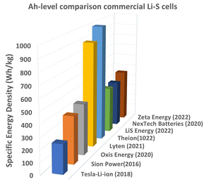 | ||
| Fig. 1 Commercial and research-based energy density (Ah) targets (300–600 Wh kg−1 of LSB pouch cells, reproduced from the data and news reports12–15,17). | ||
Lyten has fast-tracked its timeline with a 3D graphene-based material as a sulfur host for cathodes to produce Li–S cells. Lyten has raised over $625 million in total equity investment, which includes a $200 million Series B round led by Prime Movers Lab in September 2023. Additionally, the company has a letter of intent for a $650 million loan from the U.S. Export-Import Bank.17 LiS energy is currently positioning itself as a semi-solid Li–S battery manufacturer and anticipated its Gen-3 technology with a gravimetric capacity of 400 Wh kg−1 and a volumetric capacity of 540 Wh L−1.13 However, their R&D is also focusing on full-solid-state batteries through collaborative research at Deakin University. Battery reports 202218 shows the funding, patent portfolio and chemistries of existing Li–S battery companies (Fig. 2).
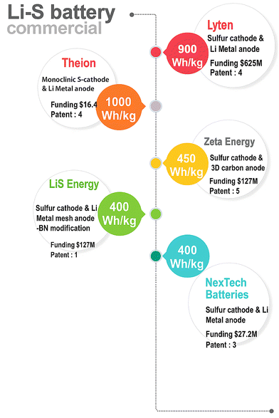 | ||
| Fig. 2 Commercial energy density targets from existing Li–S companies (drawn based on the data of ref. 18 and news reports). | ||
1.1. Limitations of liquid Li–S batteries
Although lithium–sulfur (Li–S) batteries exhibit promising features, they face considerable challenges in achieving commercialization. The process of converting elemental sulfur (S8) to lithium sulfide (Li2S) involves a series of multi-step reduction reactions (eqn (1)–(4) and Fig. 3b). During the discharge process, higher-order lithium polysulfides (Li2Sn, where 8 ≤ n ≤ 3) are generated as sulfur interacts with lithium ions in the liquid electrolyte. Subsequently, these highly soluble polysulfides are transformed into lower-order, insoluble polysulfides (Li2S2/Li2S), as illustrated in Fig. 3(a and b).| S8 + 2Li+ + 2e− → Li2S8 | (1) |
| Li2S8 + 2Li+ + 2e− → 8Li2S4 | (2) |
| 2Li2S4 + 4Li+ + 4e− → 4Li2S2 | (3) |
| 4Li2S2 + 8Li+ + 8e− → 8Li2S | (4) |
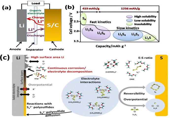 | ||
| Fig. 3 (a) Working principle, (b) polysulfide species formation in different operational voltage ranges and (c) degradation mechanisms of Li–S batteries (molecular structure: ref. 19). This figure has been adapted/reproduced from ref. 19 with permission from Wiley copyright 2021. | ||
Fig. 3c clearly shows the issues hindering the progress of Li–S technology. During the cycling, the polysulfides accumulated at the anode physically block the coverage of the active sites, resulting in inefficient transfer of lithium ions and degradation in the battery performance. Second, the shuttle effect, where the soluble higher order polysulfide shuttles between the anode and cathode at discharge, eventually reduces the shelf life and lifespan of the battery.8,20 Finally, the Li-metal anode commonly used in Li–S batteries is susceptible to reaction with the polysulfides, forming lithium sulfide (Li2S) – a non-conductive and non-electrochemically active species. These further compromise the battery efficiency.21
1.2. Solid-state polymer electrolytes
To curb the issues of shuttle effects and polysulfide blocking, solid-state Li–S batteries represent a promising technological advancement.22 These batteries transform next-generation battery technology by substituting liquid electrolytes with solid ones, solid state batteries (SSBs). Solid electrolytes provide numerous benefits, such as improved safety due to their non-flammability and the ability to suppress the polysulfide shuttle effect by physically hindering the diffusion of polysulfides within the battery.23 However, solid-state batteries currently face challenges with brittleness and interfacial stability at the electrode–electrolyte interface. This brittleness can lead to mechanical failure during battery operation, while poor interfacial stability can hinder ionic conductivity and battery performance.23–25 The constraints of SSBs have led to increased demand in polymer electrolytes for Li–S batteries, due to significant advantages. Polymer electrolytes offer a hybrid approach that combines the advantages of solid and liquid electrolytes, providing interfacial compatibility and flexibility.26–28 They offer the safety benefits and potential for improving interfacial stability of solid electrolytes while maintaining some of the flexibility and processability of liquid electrolytes (Fig. 4).26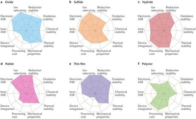 | ||
| Fig. 4 Properties of different solid-state electrolytes. This Fig. 4(a–f) has been reproduced from ref. 26 with permission from Springer Nature copyright 2017. | ||
Polymer electrolytes offer several advantages over conventional liquid electrolytes that make them particularly promising for Li–S batteries.27,29,30 Fig. 5 shows web of science estimation of patents and literature on “polymer in Li–S batteries” as of 2025 and Pie chart distribution of polymer electrolytes, cathodes and binders for Li–S batteries.
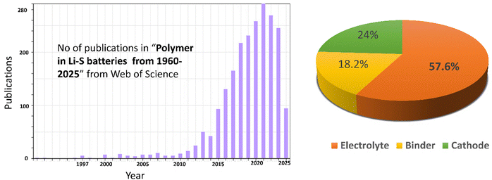 | ||
| Fig. 5 Works on “polymer in Li–S batteries” (1960–2025) and Pie chart distribution of polymers (electrolytes, cathodes and binders). | ||
Polymer-based electrolytes offer a significant advantage over their liquid counterparts and inorganic solid electrolytes in Li–S batteries.30
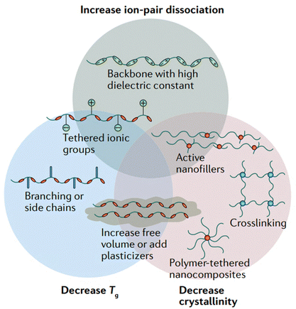 | ||
| Fig. 6 Approaches to increase the ionic conductivity of polymer electrolytes. This figure has been reproduced from ref. 19 with permission from Springer Nature copyright 2025. | ||
1.2.4.1. Polar group incorporation. Incorporating polar groups into a base material achieves two crucial goals: it enhances lithium-ion interaction through increased polarity and simultaneously restricts the diffusion of larger, undesirable molecules like polysulfides.
1.2.4.2. Crosslinking. Crosslinking the polymer chains can create stronger networks that may form in a polymer, hence leading to improved mechanical strength and probably reduced sulfur diffusion across molten salts.
1.2.4.3. Suppression of polysulfide dissolution. Polymer electrolytes possibly mitigate the dissolution of polysulfides. The polymeric matrix helps in blocking the dissolution of polysulfides in electrolytes and subsequent interaction.36 Additionally, specific functional groups and fillers incorporated into the polymer matrix can interact with polysulfides by chemical interaction or surface adsorption, helping in better confinement and conversion.
1.3. Market drivers and industry trends
The Li–S battery market is set to experience considerable growth driven by the increasing need for high-performance energy storage solutions.10,12 Several key factors drive this growth.1.4. Challenges with polymer electrolytes for Li–S batteries
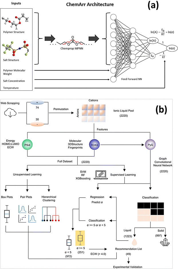
The Li–S battery market is anticipated to witness a significant growth in the near-term future for high-performance and long-lasting high energy density storage solutions. Polymer electrolytes will be one of the major advancements.30,39 However, polymer electrolytes also possess some hurdles to overcome in accelerating the commercialization of Li–S batteries.This review article explores the current cutting edge research in polymer electrolytes for Li–S batteries, highlighting the challenges and opportunities in this field. This review also delves deeper into the Li-ion conduction mechanism of polymer electrolytes, through molecular dynamics simulations and experimental validation. This review also talks about some recent developments in self-healing polymer electrolytes for smart futuristic Li–S batteries. Finally, this review discusses the environmental impact of solid state Li–S batteries, future directions, and potential breakthroughs achieved using artificial intelligence and machine learning that could pave the way for the widespread adoption with the aid of advanced polymer electrolytes in the commercial market.
2. Progress in polymer electrolytes
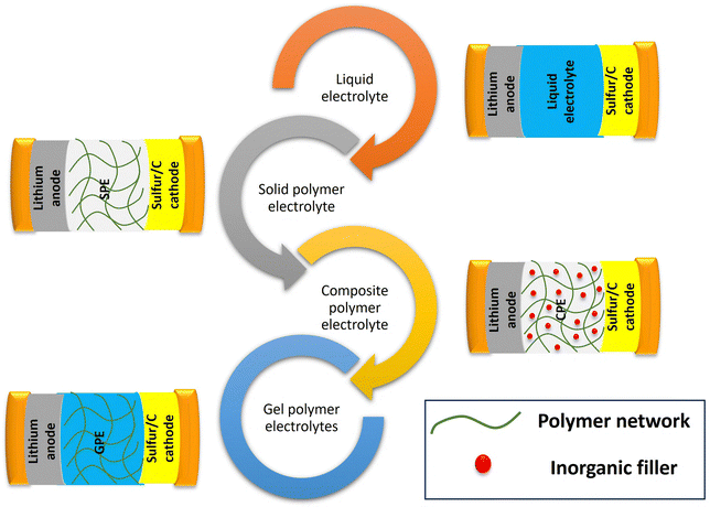
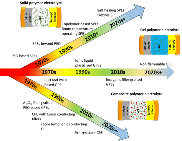
Polymer electrolytes can be classified into three main types: (a) solvent free or solid or polymer electrolytes (SPEs) (b) gel polymer electrolytes (GPEs) and (c) composite polymer electrolytes (CPEs). Fig. 7 shows the schematic depiction of the different types of electrolytes used in Li–S batteries.SPEs consist of a solid polymer matrix which facilitates lithium ion transport. It offers exceptional safety because of the absence of flammable liquids. Polyethylene oxide (PEO) is the most widely used SPE backbone for Li–S batteries,41 however its low ionic conductivity at room-temperature can limit the performance. Advancements in polymer design and the incorporation of conductive additives are being carried out to address this challenge. GPEs are a combination of SPEs and liquid electrolytes.36 GPEs can achieve comparatively higher ionic conductivity than SPEs, and good interfacial compatibility. However, in GPEs, incorporation of liquid plasticizers results in lower mechanical stability and less safety. To address the limitations of both SPEs and GPEs, CPEs have been developed. These comprise different fillers incorporated within the polymer matrix. Moreover, specific fillers can be included for dealing with specific problems connected with Li–S batteries like trapping polysulfides or increasing electronic conductivity in the cathode. SPEs have good safety characteristics but often suffer from poor ionic conduction resulting in low lithium ion transport through the battery. CPEs adopt both approaches by infusing ceramics or nanoparticles into the polymeric material. Due to their ability to enhance ionic conductivity, these additives such as ceramic materials can increase mechanical strength. They also provide other functionalities including trapping polysulfides. Polymer electrolytes have significantly witnessed a surge of interest in recent years (Fig. 5). This is demonstrably evident in the exponential growth of published research exploring these materials, encompassing polymer electrolytes highlighted over the years in Fig. 8.
2.1. Solid polymer electrolytes (SPEs)
SPEs offer electrochemical stability, safety, and flexibility, all of which are essential for solid-state lithium-sulfur batteries. Polyethylene oxide is one of the most widely studied SPEs due to their high lithium salt solvation capabilities and film forming abilities.23 The interaction of PEO with metal salts was first investigated by Fenton and explored by Armand.42 Studies showed that at elevated temperatures, molten PEO exhibits liquid-like behavior, leading to a phenomenon like the polysulfide shuttle effect observed in ether-based electrolyte solvents.43 The strong attraction between PEO and Li2Sn (n = 1–8), as evidenced by the elevated Gutmann Donor Numbers of ethylene oxide (EO) units enhances the solubility of long-chain polysulfides in PEO-based electrolytes. This phenomenon, known as the shuttle effect, has been experimentally confirmed by various research groups.44,45 In situ optical microscopy is used to investigate the structural modifications and integrity of the polymer electrolyte during the discharge process confirms color change, demonstrating the dissolution of polysulfides into the PEO-based SPE, which was further investigated by Zaghib's group through in situ SEM imaging, and UV-Vis spectroscopy revealed the formation of S42− polysulfides during discharge and S62− polysulfides during charge caused the increased interfacial resistance.46 Various techniques like infrared spectroscopy and X-ray diffraction (XRD) have been used to investigate the critical role of the electrolyte medium in addressing lithium polysulfide shuttling. The study revealed that Li2S8 dissolves more effectively in PEO compared to Li2S4. Additionally, electrochemical measurements demonstrated that PEO significantly reduces the shuttling speed of polysulfides (S82− and S42−) compared to conventional liquid electrolytes like 1,3-dioxolane (DOL) and 1,2-dimethoxyethane (DME). Notably, the study found that long-chain polysulfides exhibited a stronger shuttling effect than short-chain ones. These findings offer valuable insights for designing advanced SPEs for all-solid-state lithium-sulfur batteries. Further studies on the electrochemical behaviour of PEO/Li2Sx electrolytes suggest that Li2S4 may partially dissociate in PEO due to its limited solubility, while Li2S8 tends to fully dissociate. Interestingly, PEO hinders the mobility of short-chain polysulfides (S42−) more effectively than TFSI− anions, while Li+ diffusion remains comparable in both systems. The higher solvation of Li2S8 by PEO allows for complete dissociation into Li+ and S82−, leading to a more conductive PEO/Li2S8 electrolyte compared to PEO/Li2S4. Meanwhile, the diffusion coefficient of S82− (2 × 10⁻⁸ cm2 s−1) in PEO at 80 °C is slightly lower than that of S42− (3 × 10⁻⁸ cm2 s−1), providing valuable guidance for designing SPEs to mitigate Li2Sx transport in next-generation lithium-sulfur batteries.47 Despite being the most widely studied SPE material, PEO faces few challenges which need to be overcome. The current trend of research focuses on improving PEO based solid state electrodes.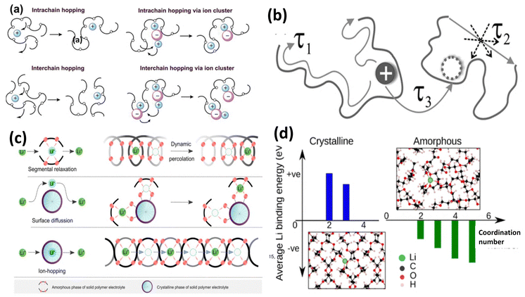 | ||
| Fig. 9 Li+ conduction in PEO, (a) in the amorphous phase. This figure has been reproduced from ref. 48 with permission from Royal Society of Chemistry copyright 2023; (b) in the amorphous and crystalline phase. This figure has been reproduced from ref. 47 with permission from American Physical Society copyright 2007; (c) ion hopping in the amorphous and crystalline state of the polymer. This figure has been reproduced from ref. 28 Springer Nature copyright 2023 and (d) molecular simulation of binding energy of Li+/PEO. This figure has been reproduced from ref. 49 with permission from American Chemical Society copyright 2018. | ||
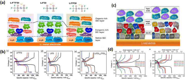 | ||
| Fig. 10 Interaction of PEO with Li salts with different anions: (a) PEO–LiFTSI, PEO–LiFSI and PEO–LiTFSI; (b) charge–discharge plots of salts in (a); (c) SEI layer formed on Li electrode with LiDFTFSI and LiTFSI salt; (d) charge–discharge plots of salts in (c). These figures have been reproduced from ref. 52 with permission from American Chemical Society copyright 2018 and from ref. 53 with permission Elsevier copyright 2019. | ||
![[triple bond, length as m-dash]](https://www.rsc.org/images/entities/char_e002.gif) N) into the polymer backbone can enhance Li-ion coordination and mobility. These groups can also disrupt the polymer's crystalline structure, promoting the amorphous phase and behavior of different organic functional groups, −CH3, −NH2, −CN, and −OH, in a PEO-based base electrolyte through molecular dynamics simulations and experimental evidence. In the absence of PEO, calculations suggest a stronger binding order of –CN > –OH > –NH2 > –CH3. Here, the –CN group appears to bind spontaneously with lithium ions due to its high binding free energy (−53.1 kJ mol−1) compared to ether oxygen (−22.8 kJ mol−1). However, when incorporated into the PEO matrix, the binding trend changes. However, the chelating effect of PEO weakens the overall binding strength of functional groups with lithium ions. Additionally, the –CN group cannot form hydrogen bonds with PEO's ether oxygen atoms while coordinating with lithium ions, further reducing its binding favourability. This highlights the importance of considering the complete PEO model when studying Li+ interactions in PEO-based electrolytes for obtaining accurate results. The trend in lithium ion binding strength follows the order: –NH2 > –OH > –CN > –CH3.56 Anions exhibit the opposite trend: –NH2 > –CN > –OH > –CH3. These differences in binding interactions influence the room-temperature conductivity and transference numbers of –PEO based SPEs.
N) into the polymer backbone can enhance Li-ion coordination and mobility. These groups can also disrupt the polymer's crystalline structure, promoting the amorphous phase and behavior of different organic functional groups, −CH3, −NH2, −CN, and −OH, in a PEO-based base electrolyte through molecular dynamics simulations and experimental evidence. In the absence of PEO, calculations suggest a stronger binding order of –CN > –OH > –NH2 > –CH3. Here, the –CN group appears to bind spontaneously with lithium ions due to its high binding free energy (−53.1 kJ mol−1) compared to ether oxygen (−22.8 kJ mol−1). However, when incorporated into the PEO matrix, the binding trend changes. However, the chelating effect of PEO weakens the overall binding strength of functional groups with lithium ions. Additionally, the –CN group cannot form hydrogen bonds with PEO's ether oxygen atoms while coordinating with lithium ions, further reducing its binding favourability. This highlights the importance of considering the complete PEO model when studying Li+ interactions in PEO-based electrolytes for obtaining accurate results. The trend in lithium ion binding strength follows the order: –NH2 > –OH > –CN > –CH3.56 Anions exhibit the opposite trend: –NH2 > –CN > –OH > –CH3. These differences in binding interactions influence the room-temperature conductivity and transference numbers of –PEO based SPEs.PEO/LiTFSI (lithium bis(trifluoromethanesulfonyl)imide) struggled to reach the theoretical capacity of sulfur in the initial cycles and experienced a significantly rapid decline in capacity. However, PEO/LiFSI (lithium bis(fluorosulfonyl)imide) (Fig. 10a) forms a stable SEI on the Li-anode causing a higher life of batteries.52 Michele Armand's group has sought to identify a series of lithium salts applicable to LSBs. The PEO/LiDFTFSI combination exhibited a different behaviour. While the –CF2H groups in LiDFTFSI improved lithium-ion conductivity by reducing anion mobility, they also reacted with PEO (Fig. 10b). Additionally, these groups contributed to a robust SEI on the lithium surface, mitigating the shuttle effect. Consequently, LiDFTFSI-based cells exhibited remarkable cyclability, exceeding 1300 cycles (3000 hours) with near-100% Coulombic efficiencies at 0.1C discharge/charge rates.53
Apart from salt modification, copolymers also played a major role in Li–S battery performance. The incorporation of a polymeric layer57,58 (such as PVDF, PIM, PVP etc.) into PEO-based SPEs represents a promising strategy for developing high-performance and long-lasting solid-state Li–S batteries. Fang et al.44 explored the use of a PVDF coating layer, demonstrating its potential in suppressing the formation of soluble lithium polysulfides and promoting a more favourable reaction mechanism for sulfur by forming a better interfacial contact in the PEO-based SPEs. The PVDF layer is believed to influence the reaction pathway by facilitating a single-step “solid–solid” conversion instead of a multistep “solid–liquid–solid” process typically observed in solid-state lithium–sulfur batteries (Fig. 11a). The presence of only one voltage plateau in the ex situ XPS data suggests the direct conversion of short-chain Li2S2 to Li2S during discharge. Additionally, high-resolution cathode mapping reveals an increase in LiS2− species after discharge to 1.85 V, with no detectable LiS4− signals. This reinforces the notion that elemental sulfur directly converts to solid Li2S2/Li2S, bypassing the formation of long-chain polysulfides during discharge. This effect is likely due to the strong adsorption capability of PEO towards these longer-chain polysulfides. Ao and his team designed a bi-layer composite incorporating a poly(vinylpyrrolidone) (PVP)/PEO layer on the cathode and a PEO/LiTFSI layer on the anode.19 The PVP layer, with its strong affinity for polysulfides due to amide groups, effectively suppressed polysulfide shuttling (Fig. 11a) with an initial capacity of 1100 mAh g−1 and sustained 347 mAh g−1 after the 200th cycle at 60 °C.19 A weight ratio of 3![[thin space (1/6-em)]](https://www.rsc.org/images/entities/char_2009.gif) :
:![[thin space (1/6-em)]](https://www.rsc.org/images/entities/char_2009.gif) 1 for PEO and polyethylene glycol dimethacrylate (PEGDMA) in a PPE polymer electrolyte yielded the best balance of electrochemical performance and the mechanical properties (Fig. 11b). This optimized PPE-1/3 electrolyte enabled Li symmetric cells to cycle stably for over 1600 hours with 929 mAh g−1.59 Additionally, Li|PPE-1/3|S cells delivered a first-cycle capacity exceeding 900 mAh g−1 at 0.2C and maintained a good average Coulombic efficiency (around 95%) after 200 cycles. This promising performance extends to high-capacity Li–S pouch cells.59 Fig. 11c shows PIM-1 effectively captures lithium polysulfide molecules within a battery and mitigates the detrimental ‘shuttle effect’ because the electrophilic (electron-attracting) groups in PIM-1, specifically 1,4-dicyanooxanthrene units, bind strongly to the polysulfides. By incorporating PIM-1 into a polyethylene oxide (PEO) composite electrolyte, researchers achieved significant improvements in a lithium–sulfur battery's performance.57
1 for PEO and polyethylene glycol dimethacrylate (PEGDMA) in a PPE polymer electrolyte yielded the best balance of electrochemical performance and the mechanical properties (Fig. 11b). This optimized PPE-1/3 electrolyte enabled Li symmetric cells to cycle stably for over 1600 hours with 929 mAh g−1.59 Additionally, Li|PPE-1/3|S cells delivered a first-cycle capacity exceeding 900 mAh g−1 at 0.2C and maintained a good average Coulombic efficiency (around 95%) after 200 cycles. This promising performance extends to high-capacity Li–S pouch cells.59 Fig. 11c shows PIM-1 effectively captures lithium polysulfide molecules within a battery and mitigates the detrimental ‘shuttle effect’ because the electrophilic (electron-attracting) groups in PIM-1, specifically 1,4-dicyanooxanthrene units, bind strongly to the polysulfides. By incorporating PIM-1 into a polyethylene oxide (PEO) composite electrolyte, researchers achieved significant improvements in a lithium–sulfur battery's performance.57
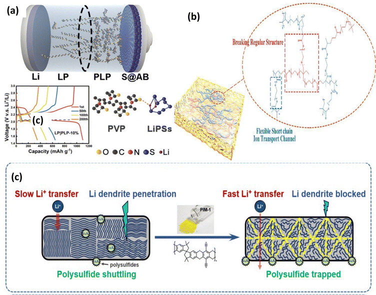 | ||
| Fig. 11 (a) Scheme of PVP–PEO PE and the charge–discharge plot. This figure is reproduced from ref. 52 with permission from John Wiley and Sons copyright 2022. (b) Synthesis process of UV-cured PPE electrolytes reproduced from ref. 59 with permission from Elsevier copyright 2023. (c) Schematic illustration of PIM reproduced from ref. 57 with permission from John Wiley and Sons copyright 2021. | ||
Fig. 12(a and b) shows a bi-grafted polysiloxane copolymer with LiTFSI and PVDF. BPSO-150%-LiTFSI-10% PVDF with σ of 7.8 × 10−-4 S cm−-1 at RT, further modified with cellulose acetate, achieving a BPSO-150%-LiTFSI-10%-PVDF + CA polymer electrolyte, shows 91.6% capacity retention after 10 cycles.64 Other than PVDF, Nafion is also a potential choice for SPEs. Li-Nafion membranes, known for their lightweight and bendable nature, are another attractive option. Their inherent electrical conductivity and ability to block electrons make them suitable for use as both solid electrolytes and separators in LSBs.65 Researchers have explored the use of PC-Li-Nafion membranes (achieved by swelling Li-Nafion with propylene carbonate) that function as a combined electrolyte and separator (Fig. 12c). This unique structure not only promotes ionic conductivity but also enhances interfacial contact within the battery, ultimately leading to improved specific capacity (Fig. 12(c and d)).65
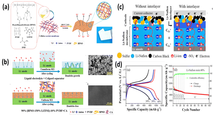 | ||
| Fig. 12 (a) and (b) Schematic of synthesis and (b) polysulfide shuttling mitigation using a BPSO-polymer electrolyte. The figures are reproduced from ref. 64 with permission from Elsevier copyright 2018, (c) scheme of (d) Li–S battery performance of the Li-Nafion electrolyte. The figures are reproduced from ref. 64 with permission from Elsevier copyright 2018. | ||
Recently, a lot of polymer electrolyte research studies have also been carried out to develop smart batteries. One of the major areas of smart batteries is self-healing polymer based batteries.66 Pei and coworkers have developed a best described all-solid-state self-healing polymer electrolyte (PTMS–HDI–BHPS–LiFSI)/poly(ether-urethane) shown in Fig. 13(a and b). The polymer contains various ether-oxygen carbonyl functionalities, and the disruption of these functionalities facilitates improved lithium ion migration, allowing for self-repair of the bond between the electrodes and electrolytes. Ultrasound imaging revealed enhanced contact between these components compared to conventional layers. This better contact helped the sulfurized polyacrylonitrile (SPAN) cathode to last longer (93% after 700 cycles) and work faster (560 mAh g−1). With a sulfur/carbon black (S@CB) cathode, the battery lasted over 350 cycles with 812 mAh g−1. Fig. 13c shows an LED powered by a pouch cell using this polymer electrolyte and SPAN cathode.67 Electrochemical performances of some reported SPEs for Li–Sulfur batteries are presented in Table 1.
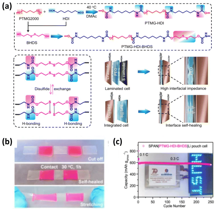 | ||
| Fig. 13 (a) Schematic depiction of the self-healing mechanism, (b) experimental process of the self-healing mechanism of polymer and (c) demonstration of a LED powered using a pouch cell with a self-healing polymer. The figures are reproduced from ref. 64 with permission from Springer Nature copyright 2024. | ||
| Polymer electrolytes | Cathodes | Ionic conductivity (S cm−1) (temperature) | Li–S battery performance (mAh g−1), retention (%) | Ref. |
|---|---|---|---|---|
| BPSO-150%-LiTFSI-10% PVDF + CA | MCNT@S | 4.0 × 10⁻⁴ (25 °C) | 987.6 (1st), 91.6% (10th) | 64 |
| PIN/SN–LiTFSI | PAN/S | 1.15 × 10⁻⁴ (RT) | 500 (1st), 95.2% (50th) | 40 |
| 6.55 × 10⁻³ (80 °C) | ||||
| PEO–PIM–LiTFSI | S/C | — | 1189 (1st), 75.7% (100th) | 57 |
| PEO/PVP | S/C | 6 × 10⁻⁴ (90 °C) | 1110 (1st), 31.26% (200th) | 19 |
| PEO–PAN–LiTFSI | S/BP-2000(go) | 1.63 × 10⁻⁵ (below RT) | 1110 (1st), 46% (100th) | 68 |
| PEO–LiITSI | S@AB | 2.58 × 10⁻⁵ (30 °C) | 910 (1st), 12.6% (200th) | 59 |
| 1.13 × 10⁻⁴ (60 °C) | ||||
| PPE-1/3 SPE | S@AB | 5 × 10⁻⁵ (30 °C) | 1215 (1st), 83.8% (10th) Pouch cells | 59 |
| 3.2 × 10⁻⁴ (60 °C) | 36.8% (200th), coin cell | |||
| PEO–LiFSI | SPAN | 1.2 × 10⁻⁵ (30 °C) | 470 (1st), 32% (400th) | 67 |
| PTMS–HDI–BHPS–LiFSI | SPAN | 6.5 × 10⁻⁵ (30 °C) | 874 (1st), 93% (700th) | 67 |
2.2. Gel polymer electrolytes (GPEs)
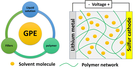
Though SPEs deliver high safety advantages in the absence of any liquid components, they have limitations like low interfacial stability and low ionic conductivity. Hence, GPEs are introduced to bridge the gap between SPEs and liquid electrolytes. They possess good mechanical strength due to a solid polymer matrix and high ionic conductivity of a minimal liquid component used as a plasticizer. Liquid electrolytes in GPEs help in improving both polymer chain mobility and ionic conductivity. GPEs offer better compatibility with electrodes compared to conventional SPEs, potentially mitigating interfacial issues like lithium dendrite growth and polysulfide shuttling. A good GPE should allow volumetric changes during charge discharge cycles. Fig. 14 shows the essential components of a GPE. Most of the GPE research focuses on tailoring the solid polymer host, liquid plasticizer, and fillers to achieve a balance between mechanical strength, ionic conductivity, and interfacial compatibility.Fig. 15a shows a cross-linked GPE incorporating fluoroethylene carbonate (FEC) to form a solid electrolyte interface (SEI) film. Notably, this GPE is achieved through a simple synthesis process without the need for initiators. The resulting GPE with the FEC additive (GPE@FEC) exhibits an excellent ionic conductivity (0.830 × 10⁻³ S cm−1 at 25 °C and 1.577 × 10⁻³ S cm−-1 at 85 °C) and a remarkably high transference number (tLi+ = 0.674). Furthermore, GPE@FEC demonstrates a strong ability to anchor polysulfides. The exceptional ionic conductivity of this GPE translates to 940 mAh g−1 at 0.2C and outstanding cycling performance lasting for 180 cycles at 0.5C.69 The GPE combines a conductive PVDF-HFP polymer matrix with a high transference number with an electrospun γ-Al2O3 nanofiber framework as shown in Fig. 15(c–g). γ-Al2O3 facilitates structural stability, and the Lewis acid–base interaction of the γ-Al2O3 nanofiber-polymer network suppresses polysulfide shuttling (841.5 mAh g−1 capacity at the end of 150 cycles at 0.1C with low decay) and promotes Li salt dissociation (1000 h stable operation at 0.5 mA cm−2). Fig. 16h shows a PEO–PAN–LLZO composite GPE membrane, which possesses outstanding mechanical and interfacial properties. It efficiently absorbs the electrolyte, inhibits the “shuttle effect”, and safeguards the lithium anode (Fig. 16i), leading to enhanced rate capability. The CGPE based Li–S battery displays 1459/942 mAh g−1 at 0.1/1C and 555 mAh g−1 at 1C after the 500th cycle.70 Liu et al. introduced a pentaerythritol tetra acrylate (PETEA)-based GPE that addresses the polysulfide shuttling problem.71 The robust PETEA matrix and its flexible passivation layer effectively suppresses polysulfide movement (dissolution). This innovative GPE exhibits an exceptionally high σ of 1.13 × 10⁻² S cm−1, a gravimetric capacity of 601.2 mAh g−1 at 1C and 81.9% (@0.5C) capacity retention after the 400th cycle due to the packed Li3N layer formed at the electrode–electrolyte interface. Peng-Qin Wang et al.36 reported a poly (1,3-dioxolane) (PDOL)-g-C3N4 thick film, with σ of 3.7 × 10⁻⁴ S cm−1, which was stable up to 5.0 V and helped in dendrite suppression. A capacity of 1150/550 mAh g−1 was achieved at 0.1/1C with 83% retention after the 100th cycle.72 Chiu and coworkers reported a polymethyl methacrylate (PMMA)-based GPE for lithium–sulfur cells with a high-loading cathode (S loading: 8–10 mg cm−2), showing 7.1 mAh cm−2 and 15 mW h cm−2.73
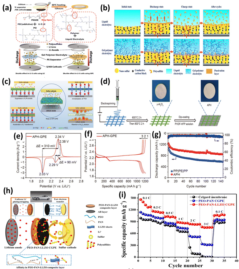 | ||
| Fig. 15 (a) Cross-linked GPE schematic representation of the shuttling mechanism. The figure is reproduced from ref. 70 with permission from American Chemical Society copyright 2021 and (b) interactions between the cathode, liquid and polymer electrolytes. The figure is reproduced from ref. 70 with permission from American Chemical Society copyright 2021. (c)–(g) Al2O3/PVDF-HFP gel polymer electrolyte for Li–S batteries. The figure is reproduced from ref. 70 with permission from Elsevier copyright 2016. (h) and (i) Schematic illustration and rate capability studies of the PEO–PAN–LLZO composite. The figure is reproduced from ref. 70 with permission from Elsevier copyright 2021. | ||
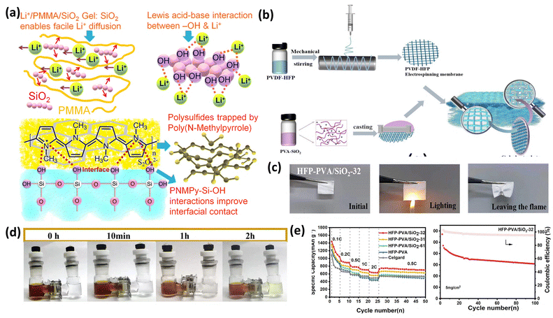 | ||
| Fig. 16 (a) Poly(N-methyl pyrrole) (PNMPy)–SiO2 mechanism for shuttling inhibition. This figure is reproduced from ref. 74 with permission from American Chemical Society copyright 2018.75 (b)–(e) Synthesis illustration and (c) LSB studies for the PVA–SiO2 based GPE. This figure is reproduced from ref. 74 with permission from American Chemical Society copyright 2018.76 | ||
Fig. 16a shows the uniform coating of a conducting Poly(N-methyl pyrrole) (PNMPy) polymer with an σ about 1 mS cm−1. Li/PMMA/SiO2 GPE with a Li–S@RGOPNMPy cathode shows 100% CE after the 500th cycle.75 Hui and coworkers have reported an asymmetric and structurally stable SiO2@PVA/PVDF-HFP, Fig. 16(b–e). These asymmetrically coated PVDF-HFP membranes exhibited excellent wettability, which is crucial for effective gelling with good ionic conductivity, surpassing that of traditional Celgard separators. With 90% sulfur cathode, this gel electrolyte exhibited 1439 mAh g−1 at 0.1C with high cycling.76 Table 2 shows the GPE performances for Li–S batteries.
| Polymer | Liquid electrolytesa | σ (10−4 S cm−1) | Li–S performance (initial (mAh g−1, retention (%)) | Ref. |
|---|---|---|---|---|
| a std: 1M LiTFSI in DOL/DME. | ||||
| PAN–PEO–LATP | Std. + 1 wt% LiNO3 | 8.61 | 1200 (1st), 80% (300th) | 77 |
| MOF–PVDF GPE | Std. + 1 wt% LiNO3 | — | 1381 (1st), 72% (200th) | 78 |
| PVdF/PEO–ZrO2 | Std. | 0.525 | 1059, 847.2 (500th) | 79 |
| PVdF | Std. + 0.4 M LiNO3 | 3 | 1675, 1000 (100th) | 80 |
| PVdF-HFP–SiO2 | 1 M LiTFSI/PMImTFSI | 1.1 | 1029, 885 (30th) | 81,82 |
| PEO | Std. + 2 wt% LiNO3 | 1.76 | 1182, 648 (100th) | 82 |
| PVdF/organo-polysulfides | 0.6 M LiTFSI in DEM/DOL + 0.4 M LiNO3 | 0.708 | 843, 484 (300th) | 83 |
| PPC SiO2 | Std. + 1 wt% LiNO3 | 0.164 | 1672, 1422.1 (500th) | 84 |
| PAA | 0.25 mol kg−1 LiTFSI in DME/DOL + 0.25 mol kg−1 LiNO3 | — | 1012, 800 (40th) | 85 |
| PMMA/PMPTMS/PVdF-HFP–SiO2 | 1 M LiPF6 in EC/DEC | 3.009 | 895, 845 (100th) | 75 |
| PMMA–SiO2 | Std. + 0.2 M LiNO3 | 1.1 | 1197, 476 (500th) | 86 |
| PVdF-HFP–Al2O3 | Std. + 0.1 M LiNO3 | 3.0 | 1150, 71 (100th) | 87 |
| PVdF-HFP–LATP | Std. + 1 wt% LiNO3 | 0.331 | 918, 458.9 (40th) | 88 |
| PEO–LAGP | 1 M LiTFSI in TEGDME | 1.15 | 725, 700 (300th) | 89 |
| PEGDA–LLZTO | Std. + 1 wt% LiNO3 | 1.34 | 1201, 656 (200th) | 90 |
| PVDF-HFP–Al2O3 | Std. + 0.2 M LiNO3 | 1.35 | 841.5 (100th) | 91 |
| PMMA–SiO2 | Std. + 1 wt% LiNO3 | 0.385 | 200 (500th) | 75 |
| PVA–SiO2 | Std. + 1 wt% LiNO3 | 1.28 | 1439, 71% 500th, (low loading) | 84 |
| PVA–SiO2 | Std. + 1 wt% LiNO3 | — | 54% (100th), high loading | 84 |
2.3. Composite polymer electrolytes
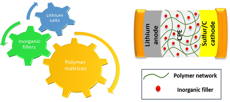
CPEs are designed to solve the limitations pertinent to both SPEs and GPEs. Unlike SPEs, CPEs incorporate inorganic fillers which improve ionic conductivity, and suitable fillers help improve the mechanical strength.2.3.1.1. Polymer matrices. These flexible backbones, often based on materials like PEO, PVDF, or PPC, provide structural integrity and safety. Their development has been ongoing from 1973 regarding Li+-ion mobility in PEO.92,93
2.3.1.2. Lithium salts. Lithium salts (e.g. LiFSI, LiTFSI etc.) dissolved in a polymer matrix provide mobile lithium ions for battery operation. This choice of salts ensures the conductivity and stability of CPEs.
2.3.1.3. Inorganic fillers. These ceramic or inorganic additives (e.g. SiO2, Al2O3, LLZO etc.) can control the properties of CPEs by tuning the mechanical properties and ionic conductivity, which helps in battery performance.
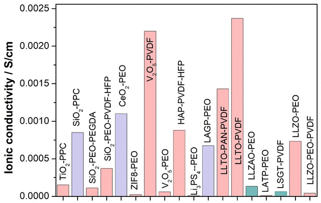
The first demonstration of a polymer–ceramic composite electrolyte came in 1982, achieved by incorporating an Al2O3 in the PEO matrix.31 This resulted in improvements in both the mechanical strength and ionic conductivity. In 1992, a study systematically investigated the effects of the wt% and particle size of a functional filler, LiAlO2, on the performance of CPEs.94 Later, PEO with mesoporous lithium aluminate was explored, which has been proved to show high ionic conductivity on filler introduction.95 Similarly, studies have shown that introducing LLTO, LLZO, and LLAZO fillers contributes to both mechanical and ionic conductivity improvements.93,96,97 Fig. 18 shows Li-ion conductivity of a few inactive and active fillers researched over the years.
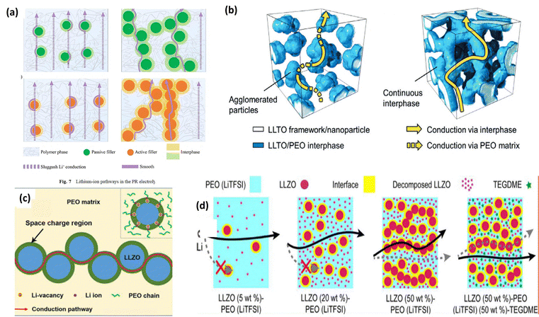 | ||
| Fig. 19 Ion conduction mechanism in a CPE. (a) Ion conduction in active and passive fillers. This figure is reproduced from ref. 101 with permission from American Chemical Society copyright 2018. (b) Ion conduction in the LLZO nanofiber framework. This figure is reproduced from ref. 102 with permission from American Chemical Society copyright 2018. (c) Ion conduction through the space charge region at the interface between a ceramic filler (Ga-LLZTO) and the polymer matrix (PEO).93 (d) NMR studies and ion conduction in LLZO–PEO–TEGDME composites. This figure is reproduced from ref. 74 with permission from American Chemical Society copyright 2018. | ||
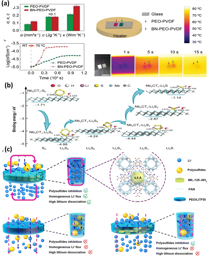 | ||
| Fig. 20 (a) Ionic and thermal conductivity at different temperatures for different durations for BN–PEO–PVDF polymer electrolytes. This figure is reproduced from ref. 108 with permission from American Chemical Society copyright 2018. (b) Polysulfide binding energy calculations for Mxene-Nb2CTx-PEO. This figure is reproduced from ref. 109 with permission from Springer Nature copyright 2023. (c) Schematic illustration of shuttling in MIL-125-NH2/PEO-LiTFSI electrolytes. This figure is reproduced from ref. 105 with permission from AAAS copyright 2024. | ||
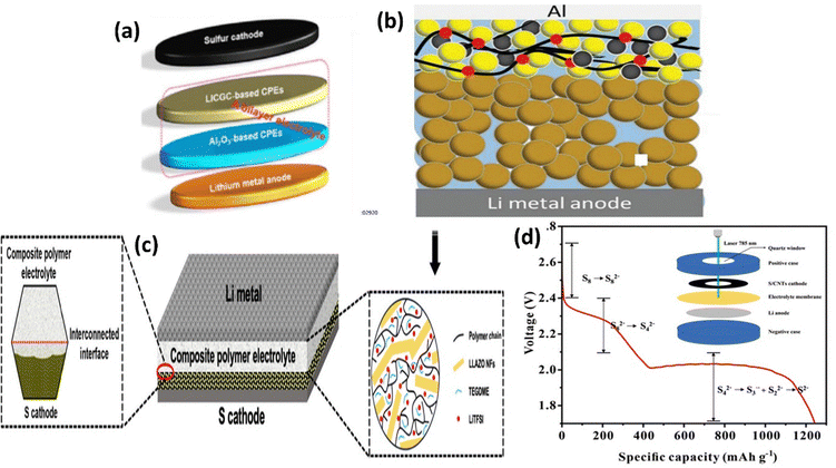 | ||
| Fig. 21 (a) Battery schematic of 3 vol% Al2O3/LICGC-CPEs. This figure is reproduced from ref. 74 with permission from American Chemical Society copyright 2018. (b) Schematic & CD curves of S@LLZO@C|S@C at 37 °C. This figure is reproduced from ref. 74 with permission from American Chemical Society copyright 2018.111 (c) LLZO based Garnet-CPE. This figure is reproduced from ref. 74 with permission from American Chemical Society copyright 2018.111 (d) Discharge curve (inset: Raman cell) of S@CNT|LLZTO/HUT|PEO|Li. This figure is reproduced from ref. 97 with permission from American Chemical Society copyright 2018. | ||
| Polymer electrolyte | Cathode | σ (S cm−1) | Li–S battery performance (mAh g−1), retention (%) | Ref. |
|---|---|---|---|---|
| PEO–PVDF–BN | C/S | 8.61 × 10⁻⁴ | 1200 (1st), 80% (300th) | 108 |
| PEO–LGPS | PAN/S | 4.2 × 10⁻⁴ | 1383 (1st), 42.5% (50th) | 112 |
| PEO–LLZO NF | C/S | 5.71 × 10⁻⁴ | 915 (1st), 56.7% (100th) | 111 |
| EO-xLSPSCl-LiTFSI | C/S | 3 × 10⁻⁴ | 1675 (1st), 80% (500th cycles) | 41 |
| PEO18–LiTFSI–LLZO–SN | PAN/S | 1.16 × 10⁻⁴ | 1029 (1st), 81.2% (60th cycles) at 0.2C | 113 |
| PEO–LLZTO@HUT4 | S/C | 0.73 × 10⁻³ (60 °C) | 1182 (1st) 92.1% (100th) | 97 |
| PEO–Al2O3–LiTFSI–PTFE | CNTs/S | — | 1415 (1st), 45.2% (120th) | 114 |
| Vr/PEO-LCSE | S/C | 12.2 × 10⁻⁴ at 25 °C | 1200 (1st), 76.6% (100th) | 115 |
| PEO-LGPS | PAN/S | 4.2 at RT | 1183 (1st), 49.8% (50th) | 116 |
| PEO-IL@NPs/ZrO2 | S/C | 4.95 × 10⁻⁴ (50 °C) 2.32 × 10⁻⁴ at (37 °C) | 986 (1st), 80% | 117 |
| PEO–LSPS | PAN/S | 1.69 (60 °C) | 1016 (0.1C, 60 °C) | 118 |
| PEO-Nb2CTx-MXene | S/C | 2.62 × 10⁻⁴ | 1149 (1st), 40% (200th) | 109 |
| PEO/LiBH4/SiO2 | S/C | 4.09 (70 °C) | 967 (70 °C) | 119 |
2.4. Enhancing mechanical and electrochemical stability with polymer electrolytes
The development of high-performance polymer electrolytes for solid-state batteries hinges on balancing mechanical robustness with exceptional ionic conductivity. A deep dive into the properties of various polymer electrolytes reveals key insights into their strengths and weaknesses. Table 4 presents a summary of various polymer electrolytes incorporating different fibers and matrices, highlighting their tensile strength and cycling lifespan. The table shows that polyimide nanofibers (NFs) in a poly(ethylene oxide) (PEO)/LiTFSI matrix demonstrate a high tensile strength of 13.9 MPa and a cycle lifespan of 500 hours at 25 °C.15 In contrast, the same fiber type combined with an LLZTO/PVDF/LiTFSI matrix offers a slightly lower tensile strength of 11.5 MPa but a longer lifespan of 1000 hours under similar conditions, suggesting that the matrix composition is critical for long-term stability [14]. Materials like polyacrylonitrile (PAN) NFs and their derivatives, such as partially cyclized PAN NFs, show impressive performance. Partially cyclized PAN NFs, for instance, exhibit a lifespan of 2000 hours, the longest among the listed materials, despite having a relatively low tensile strength of 2 MPa.21 This indicates that chemical modifications, like cyclization, can significantly enhance electrochemical stability, which is vital for commercial applications. Conversely, the β-PVDF-HFP NFs show the lowest tensile strength at 0.45 MPa but still manage a respectable lifespan of over 600 hours at 60 °C.17 The data suggest that while high mechanical strength is desirable, it does not always directly correlate with a longer lifespan, and other factors, such as the operating temperature and current density, play a significant role.| Fiber | Matrix | L μm | Tensile strength (MPa) | Galvanostatic metal stripping/plating cycle test lifespan | Ref. |
|---|---|---|---|---|---|
| Polyimide NFs | LLZTO/PVDF/LiTFSI | 20 | 11.5 | 1000 h (0.1 mA cm−2) at 25 °C | 121 |
| Polyimide NFs | PEO/LiTFSI | 17.5 | 13.9 | 500 h (0.1 mA cm−2) at 25 °C | 122 |
| PVDF/TBAC salt NFs | PEO/LiTFSI | 60–80 | 7.8 | 1000 h (0.3 mA cm−2) at 70 °C | 123 |
| β-PVDF-HFP NFs | PEO/LiTFSI | 230–300 | 0.45 | >600 h (0.2 mA cm−2) at 60 °C | 124 |
| PAN NFs | PEO/LLZTO/SN/LiTFSI | 75.7 | 3.45 | 500 h (0.1 mA cm−2) at 45 °C | 125 |
| PAN NFs | PEO/LiTFSI/PDMS | 50 | 9.64 | 1200 h (0.3 mA cm−2) at 60 °C | 126 |
| Partially cyclized PAN NFs | PEO/LiTFSI | 30 | 2 | 2000 h (0.25 mA cm−2) at 25 °C | 127 |
| PAN NFs grafted with lithiated, branched PEI | PEO/LiTFSI | 120 | 8.9 | 900 h (0.2 mA cm−2) at 60 °C | 128 |
| Polyamide 6 (PA6) | PEO/LiTFSI/SN | 85 | 4.52 | 400 h (0.1 mA cm−2), 1000 h (0.05 mA cm−2) at 30 °C | 129 |
2.5. Solid state Li–S batteries with Li2S cathode
A particularly appealing configuration involves utilizing Li2S as the cathode, which, being a prelithiated compound, facilitates the design of “lithium-metal-free” Li–Sulfur batteries. This mitigates the safety concerns associated with metallic lithium anodes and allows for the integration of high-capacity alternative anode materials like silicon–carbon (Si/C), tin–carbon (Sn/C), and carbon (C) composites. The synergistic combination of a Li2S cathode, these advanced anodes, and polymer electrolytes (PEs) offers a robust pathway towards high-performance and safer Li–S systems. Li2S cathodes offer the distinct advantage of allowing the use of Li-free anodes, simplifying battery assembly and improving safety. Conceptually, they also bypass the initial formation of soluble lithium polysulfides, reducing the infamous shuttle effect.130–134 However, Li2S is intrinsically insulating, requiring significant conductive additives, and suffers from a high activation overpotential during the first charge. Moreover, its substantial volume change (∼80%) during cycling can disrupt cathode integrity. To complement the Li2S cathode, high-capacity, Li-free anodes such as Si/C, Sn/C, and C are explored. Silicon (theoretical capacity ∼4200 mAh g−1) and tin (theoretical capacity ∼994 mAh g−1) offer high energy density but undergo drastic volume changes upon lithiation (∼300–400%). Carbon hybridization (Si/C, Sn/C) is crucial to buffer these volumetric expansions, enhance electronic conductivity, and improve structural stability.135 Carbon (C) anodes, like hard carbon, provide greater volume stability and good cycling performance, albeit with lower specific capacities than Si or Sn. However, the intrinsic ionic and electronic insulating nature of Li2S poses challenges to its electrochemical activation in solid-state systems. Achieving high Li2S utilization in ASSLSBs necessitates excellent interfacial contact between the active material, the solid electrolyte, and conductive carbon. Furthermore, the kinetics of Li2S oxidation, particularly the initial activation, can be sluggish, requiring higher charge overpotentials compared to subsequent cycles.Recent advancements demonstrate that concepts developed for liquid electrolytes, such as nanoscale encapsulation and electrocatalysis, are translatable to SPE-based ASSLSBs. For instance, Li2S@TiS2 core–shell structures facilitate efficient LiPS trapping within the particles, confirmed by in situ characterization. Crucially, the TiS2 layer actively catalyses the oxidation of Li2S, significantly lowering reaction energy barriers (e.g., from 1.73 eV to 0.57 eV for Li2S to Li2S2 conversion). This catalytic effect, corroborated by density functional theory (DFT) calculations, enables higher specific capacities, reaching up to 910 mAh g−1 Li2S, and improved cycle life.136 The integration of such optimized Li2S cathodes with SPEs and Li metal anodes has yielded an impressive cell-level specific energy of 427 Wh kg−1 surpassing those of most reported ASSLSBs. This underscores the potential of interface engineering and catalytic designs to overcome the inherent limitations of Li2S in the solid state, paving the way for truly robust and high-performance ASSLS batteries. Bruno Scrosati and group demonstrated a lithium-metal-free tin–sulfur battery employing a Sn/C anode, a Li2S/C cathode, and a polyethylene oxide/lithium trifluoromethanesulfonate (PEO/LiCF3 SO3) polymer matrix based gel polymer electrolyte (CGPE).137 This setup achieved an energy density up to 2000 Wh kg−1 with stable cycling, effectively suppressing lithium sulfide dissolution. Silicon (Si) anodes are promising for batteries, but their volume expansion causes short lifetimes. A new Si anode with 70 wt% Si nanoparticles within MXene hollow nanofibers (Si@MHF) delivers high capacity and excellent stability over 200 cycles. Solid-state Li2S‖SPE‖Si full cells, using this anode and a Li2S cathode, show high energy density, long cycle life, and remarkable safety, even under abuse conditions.138 Jiarui He et al. present a Li2S–Co9S8/Co cathode for anode-free Li–S batteries that stabilizes Li deposition and mitigates polysulfide shuttling. Co9S8/Co electrocatalysts provide nucleation sites for uniform Li2S distribution and catalyse Li–S redox, enhancing Li2S utilization. The Li2S–Co9S8/Co cathode achieved 969 mAh g−1 initially, maintaining 582 mAh g−1 over 100 cycles in anode-free cells. Incorporating tellurium (Te) significantly improved performance, yielding 1025 mAh g−1 initially and 865 mAh g−1 after 100 cycles (84% retention). Pouch cells delivered 776 mAh g−1 at C/20 (4 mg cm−2) Li2S, 4.5 μL mg−1 electrolyte, demonstrating a promising path for practical, low-cost Li–S batteries (Fig. 22).139
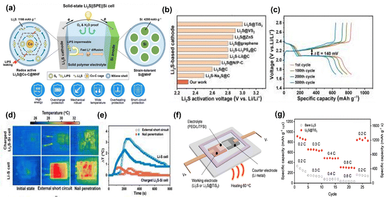 | ||
| Fig. 22 (a) Schematic diagram of Si/C anode|Li2S cathode, (b) comparison of different Li2S based cathode activation voltage, (c) charge discharge curve at different cycles, (d) external short circuit and nail penetration, and (e) temperature simulation for the Si/C anode. These figures are reproduced from ref. 137 with permission from AAAS copyright 2022. (f) Schematic of TiS2 anode|Li2S cathode (g) rate capability studies of TiS2 anode|Li2S cathode. This figure is reproduced from ref. 138 with permission from American Chemical Society copyright 2020. | ||
These collective advancements, particularly in prelithiated Li2S cathodes and innovative anode-free designs, mark a pivotal moment for solid state lithium–sulfur battery technology and provide a crucial foundation for next-generation energy storage solutions.
2.6. Multifunctional separators for Li–S batteries
Li–S batteries are increasingly recognized as a multifunctional design platform that critically shapes electrochemical performance. Beyond preventing short circuits, separator engineering is now central to addressing the polysulfide shuttle, stabilizing lithium metal, and enabling safety and cycle life improvements.1402.6.1.1. Physical blocking. Ion-selective architectures such as electrospun nanofibers or graphene oxide layers suppress polysulfide transport through tortuous diffusion pathways while maintaining Li+ conductivity.141
2.6.1.2. Chemical adsorption. Polar metal oxides (Al2O3, Fe3O4, high entropy oxides)142,143 and heteroatom-doped carbons6 provide abundant Lewis acid sites that immobilize polysulfides, retaining sulfur within the cathode vicinity.
2.6.1.3. Catalytic conversion. Catalytically active coatings (MoS2, TiS2, and MXenes) accelerate polysulfide reduction to insoluble Li2S, lowering kinetic barriers and minimizing the shuttle duration.144
| Separator novelty | Performance | Ref. | |
|---|---|---|---|
| 1 | Dual-coated separator combining a solid electrolyte (LiAlO2) | Excellent cycling stability, with only a 0.03% capacity loss per cycle over 500 cycles at a high current of 5C, and a high capacity of 800 mAh g−1 even with an ultra-high sulfur loading | 145 |
| 2 | Pore-filling solid electrolyte (PFSE) | The battery demonstrates high performance with a Li-ion conductivity of 0.604 mS cm−1, superior mechanical strength of 200 MPa, and e4xcellent long-term cycling stability, retaining 95% of its initial capacity after 200 cycles | 146 |
| 3 | A polyurethane (PU)-based solid electrolyte (self healing) | Specific capacity of approximately 610 mAh g−1 after 125 cycles | 147 |
| 4 | Prussian blue@MXene, and polypropylene | High initial capacity (1042.6 mAh g−1), excellent rate capability (90% capacity retention at 1.0C), and outstanding long-term stability (674.1 mAh g−1 after 200 cycles) | 148 |
| 5 | MoS2/graphene | MoS2/graphene interlayer delivers an initial discharge capacity of 1642 mAh g−1, and the reversible capacity remains at 720 mAh g−1 after 100 cycles | 2 |
| Anode | Cathode | Electrolyte | Electrochemical performance | Ref. |
|---|---|---|---|---|
| Li | S/C | Soft PEO10LiTFSI polymer | Demonstrated 470 Wh kg−1 in pouch Li–S batteries, focusing on electrolyte immobilization and polysulfide confinement | 149 |
| Li/Cu composite | S/KB | Quasi-solid-state PDOL-SiCl4-DE | Excellent cycling stability with a discharge capacity of 189 mAh after 30 cycles at 0.2C and 167 mAh after 50 cycles at 0.3C (with ∼360 mg S loading). Initial open-circuit voltage of 2.176 V | 150 |
| 50-μm-thick Li laminated on Cu foil (N/P ratio of 2.4) | Carbon black-S (75 wt% S, 4 mg cm−2 loading) | Lean electrolyte (2.6 μL mg S−1), implied PEI-IEM-based GPE | Fabricated a 10-Ah-grade pouch cell achieving 412.7 Wh kg−1 (based on a 50.45 g cell). Maintained 75% of initial capacity after 30 cycles and exhibited enhanced safety with flame-retardant properties | 151 |
| Li (integrated with a solid polymer electrolyte) | SPAN (integrated with a solid polymer electrolyte) | PTMG-HDI-BHDS/LiFSI solution (solid polymer electrolyte – SPE) | Delivered an initial discharge capacity of 602 mAh g SPAN−1 at 0.3C. Demonstrated exceptional cycling stability, retaining 560 mAh g SPAN−1 with >99% Coulombic efficiency after 700 cycles (93% capacity retention). A high-loading cathode (6.8 mg cm−2 SPAN) cell yielded 647 mAh g−1 (4.4 mAh cm−2 areal capacity) at 0.1C over 110 cycles. Pouch cells maintained 561 mAh g SPAN−1 with 91.7% retention after 250 cycles | 67 |
| Implied Li-based (All-Solid-State) | Implied sulfur-based (All-Solid-State) | 3D MPPL composite solid electrolyte (CSE) with ordered MIL-125–NH2 in PEO-based electrolyte (8.3 × 10⁻⁴ S cm−1 at 60 °C) | Pouch cells showed robust performance at 60 °C, maintaining 1017.4 mAh g−1 at 0.1C for 30 cycles, and >323.2 mAh g−1 after 400 cycles at 0.5C. Exhibited notable flexibility and superior safety under destructive conditions, highlighting potential for flexible electronics | 152 |
| Li3.75Si | AB@S | LPSCLiIn | Operates at 270 MPa stack pressure with a current density of 1. It provides 1512 mAh g−1 capacity within 1–2.6 V, retaining 70.6% after 30 cycles | 153 |
| LiIn | CBC@S | PTFE | Requires 500 MPa stack pressure and a current density of 0.15. It delivers 1500 mAh g−1 capacity within 1–2.4 V, showcasing exceptional 99% retention after 30 cycles | 154 |
| Li | C/S/LGPS-SRm) | LPSCl | Functions at 300 MPa stack pressure with a very low current density of 0.01. It yields 1169 mAh g−1 capacity from 1.5–2.8 V, maintaining 81% after 10 cycles | 155 |
| Li | S@C | PTFE | Operates at 0.17 current density within 1.5–2.8 V, providing 767 mAh g−1 capacity | 156 |
| Li | LPSf@LPSCl | LPSCl | Operates at a very low 5–10 kPa stack pressure with 0.21 mA cm−2 current density. It delivers 1064 mAh g−1 capacity across a broad 0.8–2.4 V range | 137 |
3. Environmental impacts of polymer electrolyte systems
The environmental implications of any technological advancement are pivotal for a sustainable future. Such implications extend beyond greenhouse gas emissions to encompass material toxicity and resource depletion. In comparison to Li-ion batteries, Li–Sulfur batteries exhibit greater environmental sustainability. This is evidenced by their higher environmental characteristic index, which clearly positions them as the cleaner technology157 (Fig. 23).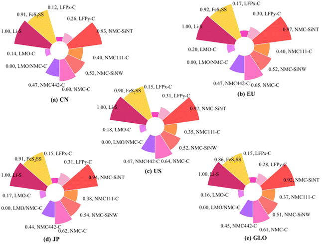 | ||
| Fig. 23 Environmental characteristic index of different battery technologies in different countries. This figure is reproduced from ref. 157 with permission from Springer Nature copyright 2023. | ||
Fig. 24a and b illustrate the performance metric scores for ternary batteries. NVP has the highest indicator score (6.63 × 10⁻⁷), while Li–sulfur has the lowest (8.96 × 10⁻⁹). In terms of material vulnerability, the unstable supply of critical raw materials, such as lithium, nickel, and cobalt, significantly impacts the supply chain of battery technologies, which puts environmental risk of Li–S batteries lower in terms of material vulnerability as sulfur is a highly abundant material.158 Fig. 24c illustrates that the Li–S battery (61.3 kWh) is significantly more environmentally benign than NCM/Graphite (63.8 kWh)159 with 18.4% less greenhouse gas emission for 320 km. Using cradle-to-gate LCA, a GWP of 105 kg CO2e/kWh was reported for a conventional Li–S battery pack.160 Popien et al. estimated the GWP of all-solid-state batteries to range from 80 to 123 kg CO2e/kWh, for Li–S/NMC622 based battery packs, respectively.161 Even lower GWP of 52 to 64 kg CO2e/kWh is reported for all-solid-state Li–S batteries.162
 | ||
| Fig. 24 (a) and (b) Performance metrics and material vulnerability scores for different battery chemistries.158 This figure is reproduced with permission from Elsevier copyright 2025. (c) Comparison between commercial NCM-G and Li–S for environmental impact parameters.160 This figure is reproduced from ref with permission from Elsevier copyright 2017. | ||
Fig. 24a and b illustrate the varying sustainability impacts associated with different polymer electrolytes (PAN, PEO, PPC, PCL, PVDF, and PPL-PPC-PCL). Among these, PAN exhibits the most significant negative environmental effects, while PEO exhibits the least.163 Additionally, Fig. 24c presents the global warming potential of various solid-state electrolytes, ranging from 0.37 to 10.64 kilograms of CO2 equivalent per gram of material, significantly lower than those of liquid electrolytes (Fig. 25).
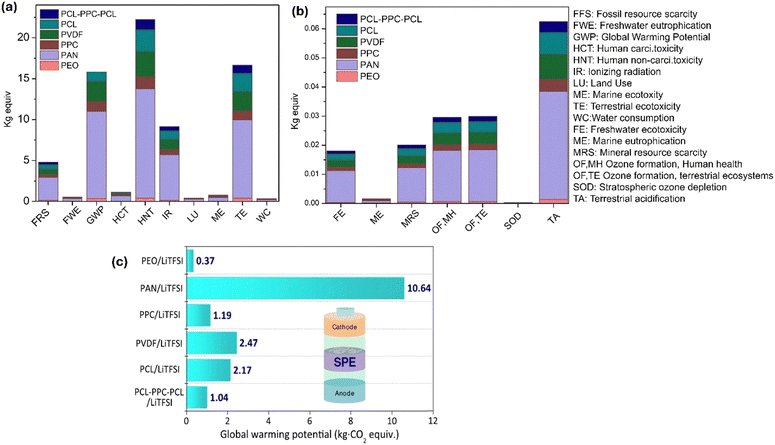 | ||
| Fig. 25 (a) and (b) Environmental impact parameters for polymer electrolytes. (c) GWP estimation for SPEs. This figure is reproduced from ref. 163 with permission from Wiley copyright 2022. | ||
For polymer ceramic electrolytes, in addition to polymer and battery materials the fillers also need to be included for the study of environmental and life cycle analysis in the future, which will also consider the vulnerability and the toxicity potential.
4. Conclusions and future directions for polymer electrolytes
This comprehensive review highlights the profound and accelerating progress in polymer electrolytes for Li–S batteries, driven by sophisticated nanoscale strategies. We have explored types of different polymer electrolytes, their journey from fundamental synthesis to advanced applications, demonstrating their significant advantages over liquid counterparts in safety, thermal and mechanical stability, and sustainability. A decade of dedicated research has advanced various classes of polymer electrolytes—solid, gel, and composite—showcasing their evolving performance metrics, progress and the persistent challenges. This review further underscored their favourable environmental impact compared to conventional lithium-ion batteries. These advancements stem from the judicious design of highly efficient nanostructured polymer matrices, the strategic incorporation of multi-functional nanofillers, and precision-engineered interfacial techniques. Collectively, these innovations have demonstrably enhanced ionic conductivity, electrochemical stability, and, critically, electrode–electrolyte compatibility, pushing the boundaries of what is achievable. Looking ahead, the burgeoning frontiers of adaptive “smart” electrolytes, capable of responding dynamically to operational conditions, anode free LSBs with Li2S cathodes and polymer electrolytes, and the powerful integration of machine learning for rational materials design, represent exceptionally promising avenues poised to dramatically accelerate the development and deployment of next-generation polymer electrolytes. However, to fully unleash their potential, future strategies must embrace a multifaceted approach.4.1. Optimizing self-healing mechanisms and shuttling mitigation
Future research should delve deeper into self-healing triggers (stress, temperature) for targeted design and tailoring the healing properties for specific battery needs.66,164 This will be coupled with investigations into how these same mechanisms can further suppress lithium polysulfide shuttling, a critical challenge in Li–S batteries.4.2. Balancing key performance parameters: interfacial stability and ionic conductivity
Development of polymer electrolytes to deliver superior interfacial stability (minimizing resistive layers at the electrode interface) and enhance ionic conductivity for efficient Li-ion transport within the battery demands innovation in electrode–electrolyte design, which includes Li metal–electrolyte interfaces as well as cathode/electrolyte interfaces.4.3. AI and machine learning: accelerating innovation
In summary, polymer based solid electrolytes offer an indispensable and robust pathway toward realizing scalable, safe, and truly sustainable Li–S battery technologies. These materials offer safety due to their inflammability and help to mitigate the “shuttle effect”, which is the main bottleneck of current Li–S industries. With advancements like self-healing, leveraging AI/ML will accelerate the development. Furthermore, the modification of ionic conductivity and stability using polymer electrolytes will also open avenues in the exploration and development of more materials. It marks a fundamental paradigm shift that is critically aligned with the urgent global imperative for seamless renewable energy integration and the widespread adoption of electrified transportation.
Conflicts of interest
There is no conflict of interest to declare.Data availability
No primary research results, software or code have been included and no new data were generated or analysed as part of this review.Acknowledgements
The authors would like to acknowledge the National University of Singapore and CRP and NRF grants.References
- J. O’Heir, Mech. Eng., 2017, 139, 10–11 Search PubMed.
- K. Y. Bae, S. H. Cho, B. H. Kim, B. D. Son and W. Y. Yoon, Materials, 2019, 12(12), 2025 CrossRef CAS PubMed.
- Y. Cui, J. Wan, Y. Ye, K. Liu, L. Y. Chou and Y. Cui, Nano Lett., 2020, 20, 1686–1692 CrossRef CAS PubMed.
- J. B. Goodenough and K. S. Park, J. Am. Chem. Soc., 2013, 135, 1167–1176 CrossRef CAS PubMed.
- X. Zeng, M. Li, D. Abd El-Hady, W. Alshitari, A. S. Al-Bogami, J. Lu and K. Amine, Adv. Energy Mater., 2019, 9, 1–25 Search PubMed.
- M. Zhao, B. Q. Li, X. Q. Zhang, J. Q. Huang and Q. Zhang, ACS Cent. Sci., 2020, 6, 1095–1104 CrossRef CAS.
- A. Deshmukh, M. Thripuranthaka, V. Chaturvedi, A. K. Das, V. Shelke and M. V. Shelke, Prog. Energy, 2022, 4, 042001 CrossRef CAS.
- T. Ould Ely, D. Kamzabek, D. Chakraborty and M. F. Doherty, ACS Appl. Energy Mater., 2018, 1, 1783–1814 CrossRef CAS.
- D. Eroglu and J. E. Soc, J. Electrochem. Soc., 2015, 162, A982 CrossRef CAS.
- Battery 2030: Resilient, sustainable, and circular, https://www.mckinsey.com/industries/automotive-and-assembly/our-insights/battery-2030-resilient-sustainable-and-circular Search PubMed.
- Reuters, China to invest more than $830min in solid state battery research, 2024 Search PubMed.
- G. Zhou, H. Chen and Y. Cui, Nat. Energy, 2022, 7, 312–319 CrossRef CAS.
- Li-S Energy achieves 45% increase in volumetric energy density with new 20-layer semi-solid state lithium sulfur battery.
- Battery Start-up Theion Unveils Li-S “Crystal Battery” for Mobile Applications - Green Car Congress.
- Lyten Launches Lithium-Sulfur Battery Platform, https://theevreport.com/lyten-launches-lithium-sulfur-battery-platform.
- HARTENERGY, Lyten’ s Pilot Plant to Transform Natgas to Lithium-sulfur Batteries, 2023.
- https://lyten.com/2025/07/28/lyten-secures-more-than-200-million-in-investment-to-support-its-ongoing-acquisition-strategy/.
- Volta Foundation, https://volta.foundation/battery-report-2024.
- G. Bieker, V. Küpers and M. Kolek, et al., Commun. Mater., 2021, 2, 37 CrossRef CAS.
- J. He and A. Manthiram, Energy Storage Mater., 2019, 20, 55–70 CrossRef.
- A. Manthiram, Y. Fu and Y. S. Su, Acc. Chem. Res., 2013, 46, 1125–1134 CrossRef CAS.
- M. Pasta, D. Armstrong, Z. L. Brown, J. Bu, M. R. Castell, P. Chen, A. Cocks, S. A. Corr, E. J. Cussen, E. Darnbrough, V. Deshpande, C. Doerrer, M. S. Dyer, H. El-Shinawi, N. Fleck, P. Grant, G. L. Gregory, C. Grovenor, L. J. Hardwick, J. T. S. Irvine, H. J. Lee, G. Li, E. Liberti, I. McClelland, C. Monroe, P. D. Nellist, P. R. Shearing, E. Shoko, W. Song, D. S. Jolly, C. I. Thomas, S. J. Turrell, M. Vestli, C. K. Williams, Y. Zhou and P. G. Bruce, J. Phys Energy, 2020, 2(3), 032008 CrossRef CAS.
- J. Castillo, L. Qiao, A. Santiago, X. Judez, A. S. de Buruaga, G. Jimenez, M. Armand, H. Zhang and C. Li, Energy Mater., 2022, 2, 200003 Search PubMed.
- E. Quartarone and P. Mustarelli, Chem. Soc. Rev., 2011, 40, 2525–2540 RSC.
- H. D. Lim, J. H. Park, H. J. Shin, J. Jeong, J. T. Kim, K. W. Nam, H. G. Jung and K. Y. Chung, Energy Storage Mater., 2020, 25, 224–250 CrossRef.
- A. Manthiram, X. Yu and S. Wang, Lithium battery chemistries enabled by solid-state electrolytes, Nat. Rev. Mater., 2017, 2, 16103 CrossRef CAS.
- Q. Wu, M. Fang, S. Jiao, S. Li, S. Zhang, Z. Shen, S. Mao, J. Mao, J. Zhang, Y. Tan, K. Shen, J. Lv, W. Hu, Y. He and Y. Lu, Nat. Commun., 2023, 14, 6296 CrossRef CAS PubMed.
- Z. Song, F. Chen, M. Martinez-Ibañez, W. Feng, M. Forsyth, Z. Zhou, M. Armand and H. Zhang, Nat. Commun., 2023, 14, 4884 CrossRef CAS PubMed.
- K. Li, J. Wang, Y. Song and Y. Wang, Nat. Commun., 2023, 14, 2789 CrossRef CAS.
- V. Di Noto, S. Lavina, G. A. Giffin, E. Negro and B. Scrosati, in Electrochimica Acta, Elsevier Ltd, 2011, vol. 57, pp. 4–13 Search PubMed.
- J. E. Weston and B. C. H. Steele, Solid State Ionics, 1982, 7(1), 75–79 CrossRef CAS.
- K. Jeddi, M. Ghaznavi and P. Chen, J. Mater. Chem. A, 2013, 1, 2769–2772 RSC.
- L. Z. Fan, H. He and C. W. Nan, Nat. Rev. Mater., 2021, 6, 1003–1009 CrossRef CAS.
- X. Li, S. Liu, J. Shi, M. Huang, Z. Shi, H. Wang and Z. Yan, Chem. Eng. J., 2023, 468, 143795 CrossRef CAS.
- Q. Zhao, S. Stalin, C. Z. Zhao and L. A. Archer, Nat. Rev. Mater., 2020, 5, 229–252 CrossRef CAS.
- J. Qian, B. Jin, Y. Li, X. Zhan, Y. Hou and Q. Zhang, J. Energy Chem., 2021, 56, 420–437 CrossRef CAS.
- J. T. Frith, M. J. Lacey and U. Ulissi, Nat. Commun., 2023, 14, 420 CrossRef CAS PubMed.
- C. Randall, SAIC to supply IM Motors EVs with solid-state batteries, 2024 Search PubMed.
- X. Yu and A. Manthiram, Energy Storage Mater., 2021, 34, 282–300 CrossRef.
- D. Dong, B. Zhou, Y. Sun, H. Zhang, G. Zhong, Q. Dong, F. Fu, H. Qian, Z. Lin, D. Lu, Y. Shen, J. Wu, L. Chen and H. Chen, Nano Lett., 2019, 19, 2343–2349 CrossRef CAS PubMed.
- Y. Su, X. Zhang, C. Du, Y. Luo, J. Chen, J. Yan, D. Zhu, L. Geng, S. Liu, J. Zhao, Y. Li, Z. Rong, Q. Huang, L. Zhang, Y. Tang and J. Huang, Small, 2021, 18(29), 2202069 CrossRef.
- M. Armand, Solid State Ion, 1983, 9–10, 745–754 CrossRef CAS.
- B. Zhang, J. Wu, J. Gu, S. Li, T. Yan and X. P. Gao, ACS Energy Lett., 2021, 6, 537–546 CrossRef CAS.
- R. Fang, H. Xu, B. Xu, X. Li, Y. Li and J. B. Goodenough, Adv. Funct. Mater., 2021, 31(2), 2001812 CrossRef CAS.
- G. Di Donato, T. Ates, H. Adenusi, A. Varzi, M. A. Navarra and S. Passerini, Batteries Supercaps, 2022, 5(7), e202200097 CrossRef CAS.
- H. Marceau, C. S. Kim, A. Paolella, S. Ladouceur, M. Lagacé, M. Chaker, A. Vijh, A. Guerfi, C. M. Julien, A. Mauger, M. Armand, P. Hovington and K. Zaghib, J. Power Sources, 2016, 319, 247–254 CrossRef CAS.
- E. Ahiavi, P. Soudant, D. Devaux and R. Bouchet, Electrochim. Acta, 2024, 488, 144202 CrossRef CAS.
- S. Xue, Y. Liu, Y. Li, D. Teeters, D. W. Crunkleton and S. Wang, Electrochim. Acta, 2017, 235, 122–128 CrossRef CAS.
- D. Das, A. Chandrasekaran, S. Venkatram and R. Ramprasad, Chem. Mater., 2018, 30, 8804–8810 CrossRef CAS.
- Z. Wang, B. Al Alwan, W. Fawaz and K. Y. S. Ng, J. Electroanal. Chem., 2024, 954, 118017 CrossRef CAS.
- H. Zhang, C. Liu, L. Zheng, F. Xu, W. Feng, H. Li, X. Huang, M. Armand, J. Nie and Z. Zhou, Electrochim. Acta, 2014, 133, 529–538 CrossRef CAS.
- G. G. Eshetu, X. Judez, C. Li, M. Martinez-Ibañez, I. Gracia, O. Bondarchuk, J. Carrasco, L. M. Rodriguez-Martinez, H. Zhang and M. Armand, J. Am. Chem. Soc., 2018, 140, 9921–9933 CrossRef CAS.
- H. Zhang, U. Oteo, X. Judez, G. G. Eshetu, M. Martinez-Ibañez, J. Carrasco, C. Li and M. Armand, Joule, 2019, 3, 1689–1702 CrossRef CAS.
- Z. Jia, Y. Liu, H. Li, Y. Xiong, Y. Miao, Z. Liu and F. Ren, J. Energy Chem., 2024, 92, 548–571 CrossRef CAS.
- F. Yuan, H. Z. Chen, H. Y. Yang, H. Y. Li and M. Wang, Mater. Chem. Phys., 2005, 89, 390–394 CrossRef CAS.
- H. Hua, X. Yang, P. Zhang and J. Zhao, J. Phys. Chem. C, 2023, 127, 17324–17334 CrossRef CAS.
- Y. Ji, K. Yang, M. Liu, S. Chen, X. Liu, B. Yang, Z. Wang, W. Huang, Z. Song, S. Xue, Y. Fu, L. Yang, T. S. Miller and F. Pan, Adv. Funct. Mater., 2021, 31(47), 2104830 CrossRef CAS.
- Z. Ao, Y. Zou, H. Zou, Y. Huang and N. Chen, Chem, 2022, 28(34), e202200543 CrossRef CAS PubMed.
- Z. Ao, Y. Zou, H. Li, N. Chen, Y. Huang and Y. Liang, Sustainable Mater. Technol., 2023, 38, e00712 CrossRef CAS.
- V. R. Jeedi, K. K. Ganta, Y. Mallaiah, R. Swarnalatha, S. N. Reddy and A. S. Chary, J. Polym. Res., 2022, 29, 64 CrossRef CAS.
- A. Abe, D. Mori, Z. Wang, S. Taminato, Y. Takeda, O. Yamamoto and N. Imanishi, ChemistryOpen, 2024, 13, e202400041 CrossRef CAS PubMed.
- G. Feuillade and P. Perche, Ion-conductive macromolecular gels and membranes for solid lithium cells, 1975, vol. 5 Search PubMed.
- S. Skaarup, K. West and B. Zachau-Christiansen, Solid State lonics, 1988, 28–30 Search PubMed.
- L. Chen and L. Z. Fan, Energy Storage Mater., 2018, 15, 37–45 CrossRef.
- J. Gao, C. Sun, L. Xu, J. Chen, C. Wang, D. Guo and H. Chen, J. Power Sources, 2018, 179–189 CrossRef.
- S. Wang and M. W. Urban, Nat. Rev. Mater., 2020, 5, 562–583 CrossRef CAS.
- F. Pei, L. Wu, Y. Zhang, Y. Liao, Q. Kang, Y. Han, H. Zhang, Y. Shen, H. Xu, Z. Li and Y. Huang, Nat. Commun., 2024, 15, 351 CrossRef CAS PubMed.
- J. Sheng, Q. Zhang, C. Sun, J. Wang, X. Zhong, B. Chen, C. Li, R. Gao, Z. Han and G. Zhou, Adv. Funct. Mater., 2022, 32(40), 2203272 CrossRef CAS.
- T. Zhang, J. Zhang, S. Yang, Y. Li, R. Dong, J. Yuan, Y. Liu, Z. Wu, Y. Song, Y. Zhong, W. Xiang, Y. Chen, B. Zhong and X. Guo, ACS Appl. Mater. Interfaces, 2021, 13, 44497–44508 CrossRef CAS PubMed.
- P. Xie, R. Yang, Y. Zhou, B. Zhang and X. Tian, Chem. Eng. J., 2022, 450(Part 3), 138195 CrossRef CAS.
- M. Liu, D. Zhou, Y. B. He, Y. Fu, X. Qin, C. Miao, H. Du, B. Li, Q. H. Yang, Z. Lin, T. S. Zhao and F. Kang, Nano Energy, 2016, 22, 278–289 CrossRef CAS.
- P.-Q. Wang, W.-W. Shao, L. Zhong, H.-F. Wu, J.-X. Li, M.-Q. Liu, Y. Mei, G. Zhang, H.-X. Liu, X.-Q. Shen and M.-X. Jing, J. Electrochem. Soc., 2023, 170, 120527 CrossRef CAS.
- L. L. Chiu and S. H. Chung, J. Mater. Chem. A, 2022, 10, 13719–13726 RSC.
- J. Zheng and Y. Y. Hu, ACS Appl. Mater. Interfaces, 2018, 10, 4113–4120 CrossRef CAS PubMed.
- R. Mukkabla, M. Ojha and M. Deepa, Electrochim. Acta, 2020, 334, 135571 CrossRef CAS.
- X. Hu, S. R. P. Silva, P. Zhang, K. Liu, S. Zhang and G. Shao, Chem. Eng. J., 2023, 467, 143378 CrossRef CAS.
- X. Wang, X. Hao, Y. Xia, Y. Liang, X. Xia and J. Tu, J. Membr. Sci., 2019, 582, 37–47 CrossRef CAS.
- D. D. Han, Z. Y. Wang, G. L. Pan and X. P. Gao, ACS Appl. Mater. Interfaces, 2019, 11, 18427–18435 CrossRef CAS PubMed.
- S. Gao, K. Wang, R. Wang, M. Jiang, J. Han, T. Gu, S. Cheng and K. Jiang, J. Mater. Chem. A, 2017, 5, 17889–17895 RSC.
- M. Agostini, D. H. Lim, M. Sadd, C. Fasciani, M. A. Navarra, S. Panero, S. Brutti, A. Matic and B. Scrosati, ChemSusChem, 2017, 10, 3490–3496 CrossRef CAS PubMed.
- M. Rao, X. Geng, X. Li, S. Hu and W. Li, J. Power Sources, 2012, 212, 179–185 CrossRef CAS.
- W. Li, Y. Pang, T. Zhu, Y. Wang and Y. Xia, Solid State Ion, 2018, 318, 82–87 CrossRef CAS.
- Y. Q. Shen, F. L. Zeng, X. Y. Zhou, A. Bang Wang, W. Kun Wang, N. Y. Yuan and J. N. Ding, J. Energy Chem., 2020, 48, 267–276 CrossRef.
- H. Huang, F. Ding, H. Zhong, H. Li, W. Zhang, X. Liu and Q. Xu, J. Mater. Chem. A, 2018, 6, 9539–9549 RSC.
- S. S. Zhang, D. T. Tran and Z. Zhang, J. Mater. Chem. A, 2014, 2, 18288–18292 RSC.
- K. Jeddi, K. Sarikhani, N. T. Qazvini and P. Chen, J. Power Sources, 2014, 245, 656–662 CrossRef CAS.
- M. Rao, X. Li, Y. Liao, X. Li and W. Li, Ionics, 2015, 21, 1937–1943 CrossRef CAS.
- Y. Xia, X. Wang, X. Xia, R. Xu, S. Zhang, J. Wu, Y. Liang, C. Gu and J. Tu, Chem. – Eur. J., 2017, 23, 15203–15209 CrossRef CAS PubMed.
- Q. Wang, Z. Wen, J. Jin, J. Guo, X. Huang, J. Yang and C. Chen, Chem. Commun., 2016, 52, 1637–1640 RSC.
- D. Shao, L. Yang, K. Luo, M. Chen, P. Zeng, H. Liu, L. Liu, B. Chang, Z. Luo and X. Wang, Chem. Eng. J., 2020, 389, 124300 CrossRef CAS.
- H. M. Wang, Z. Y. Wang, C. Zhou, G. R. Li, S. Liu and X. P. Gao, Sci. China Mater., 2023, 66, 913–922 CrossRef CAS.
- D. E. Fenton, M. Parker and P. V. Wright, Complexes of alkali metal ions with poly(ethylene oxide), 1964, vol. 6 Search PubMed.
- Z. Li, H. M. Huang, J. K. Zhu, J. F. Wu, H. Yang, L. Wei and X. Guo, ACS Appl. Mater. Interfaces, 2019, 11, 784–791 CrossRef CAS PubMed.
- M. C. Borghini, M. Mastragostino and S. Passerini, J. Electrochem. Soc., 2003, 150, A585–A590 CrossRef.
- L. Hu, Z. Tang and Z. Zhang, J. Power Sources, 2007, 166, 226–232 CrossRef CAS.
- J. Zheng and Y. Y. Hu, ACS Appl. Mater. Interfaces, 2018, 10, 4113–4120 CrossRef CAS PubMed.
- S. Wang, M. Li, G. Yan, Z. Yang, Y. Guo, X. Sun, Y. Wang, Y. Feng, H. Ding and X. Zhang, Nanoscale, 2023, 15, 12961–12971 RSC.
- J. Zheng and Y. Y. Hu, ACS Appl. Mater. Interfaces, 2018, 10, 4113–4120 CrossRef CAS PubMed.
- Z. Zhang, H. Chen, Z. Hu, S. Zhou, L. Zhang and J. Luo, Front. Energy, 2022, 16, 706–733 CrossRef.
- K. Sau, S. Takagi, T. Ikeshoji, K. Kisu, R. Sato, E. Campos dos Santos, H. Li, R. Mohtadi and S.-i Orimo, Commun. Mater., 2024, 5, 122 CrossRef CAS.
- J. Bae, Y. Li, J. Zhang, X. Zhou, F. Zhao, Y. Shi, J. B. Goodenough and G. Yu, Angew. Chem., 2018, 130, 2118–2122 CrossRef.
- J. Li, K. Zhu, Z. Yao, G. Qian, J. Zhang, K. Yan and J. Wang, Ionics, 2020, 26, 1101–1108 CrossRef CAS.
- H. Kasemägi, H. Kasemägi, M. Klintenberg, M. Klintenberg, A. Aabloo and J. O. Thomas, J. Mater. Chem., 2001, 11, 3191–3196 RSC.
- P. A. R. D. Jayathilaka, M. A. K. L. Dissanayake, I. Albinsson and B.-E. Mellander, Effect of nano-porous Al2O3 on thermal, dielectric and transport properties of the (PEO) 9 LiTFSI polymer electrolyte system, 2002.
- J. Li, F. Xie, W. Pang, Q. Liang, X. Yang and L. Zhang, Regulate transportation of ions and polysulfides in all-solid-state Li-S batteries using ordered-MOF composite solid electrolyte, 2024, vol. 10 Search PubMed.
- T. Feng, Y. Hu, L. Xu, J. Huang, S. Hu, L. Zhang and L. Luo, Mater. Today Energy, 2022, 28, 101062 CrossRef CAS.
- Z. Lei, J. Shen, W. Zhang, Q. Wang, J. Wang, Y. Deng and C. Wang, Nano Res., 2020, 13, 2259–2267 CrossRef CAS.
- X. Yin, L. Wang, Y. Kim, N. Ding, J. Kong, D. Safanama, Y. Zheng, J. Xu, D. V. M. Repaka, K. Hippalgaonkar, S. W. Lee, S. Adams and G. W. Zheng, Adv. Sci., 2020, 7(19), 2001303 CrossRef CAS PubMed.
- S.-M. Liu, M.-X. Chen, Y. Xie, D.-H. Liu, J.-F. Zheng, X. Xiong, H. Jiang, L.-C. Wang, H. Luo and K. Han, Rare Met., 2023, 42, 2562–2576 CrossRef CAS.
- P. Sivaraj, K. P. Abhilash, B. Nalini, P. Perumal, K. Somasundaram and P. C. Selvin, Macromol. Res., 2020, 28, 739–750 CrossRef CAS.
- H. Cheng, C. Yan, L. Chang, M. Dirican, R. Orenstein and X. Zhang, ACS Appl. Energy Mater., 2024, 7, 3071–3081 CrossRef CAS.
- M. Li, J. E. Frerichs, M. Kolek, W. Sun, D. Zhou, C. J. Huang, B. J. Hwang, M. R. Hansen, M. Winter and P. Bieker, Adv. Funct. Mater., 2020, 30(14), 1910123 CrossRef CAS.
- F. Chen, P. M. G. Puente, Y. Zhang, S. Cao, X. Lu, Z. Yi, Q. Shen and J. Li, Solid State Ionics, 2022, 380, 115926 CrossRef CAS.
- Y. Shi, Z. Fan, B. Ding, Z. Li, Q. Lin, S. Chen, H. Dou and X. Zhang, J. Electroanal. Chem., 2021, 881, 114916 CrossRef CAS.
- P. Zhai, N. Peng, Z. Sun, W. Wu, W. Kou, G. Cui, K. Zhao and J. Wang, J. Mater. Chem. A, 2020, 8, 23344–23353 RSC.
- M. Li, J. E. Frerichs, M. Kolek, W. Sun, D. Zhou, C. J. Huang, B. J. Hwang, M. R. Hansen, M. Winter and P. Bieker, Adv. Funct. Mater., 2020, 30(14), 1910123 CrossRef CAS.
- O. Sheng, C. Jin, J. Luo, H. Yuan, C. Fang, H. Huang, Y. Gan, J. Zhang, Y. Xia, C. Liang, W. Zhang and X. Tao, J. Mater. Chem. A, 2017, 5, 12934–12942 RSC.
- X. Li, D. Wang, H. Wang, H. Yan, Z. Gong and Y. Yang, ACS Appl. Mater. Interfaces, 2019, 11, 22745–22753 CrossRef CAS PubMed.
- X. Zhang, T. Zhang, Y. Shao, H. Cao, Z. Liu, S. Wang and X. Zhang, ACS Sustainable Chem. Eng., 2021, 9, 5396–5404 CrossRef CAS.
- S. Bandyopadhyay and B. Nandan, Mater. Today Energy, 2023, 31, 101201 CrossRef CAS.
- J. Hu, P. He, B. Zhang, B. Wang and L. Z. Fan, Energy Storage Mater., 2020, 26, 283–289 CrossRef.
- Z. Wang, J. Sun, R. Liu, Z. Ba, J. Dong, Q. Zhang and X. Zhao, Small, 2023, 19(47), 2303422 CrossRef CAS PubMed.
- L. Gao, J. Li, J. Ju, L. Wang, J. Yan, B. Cheng, W. Kang, N. Deng and Y. Li, Chem. Eng. J., 2020, 389, 124478 CrossRef CAS.
- J. Y. Lee, P. H. Chung, S. C. Yeh, T. Y. Yu, W. Y. Lee, N. L. Wu and R. J. Jeng, J. Phys. Chem. C, 2021, 125, 26339–26347 CrossRef CAS.
- L. Gao, B. Tang, H. Jiang, Z. Xie, J. Wei and Z. Zhou, Adv. Sustainable Syst., 2022, 6(3), 2100389 CrossRef CAS.
- L. Gao, J. Li, B. Sarmad, B. Cheng, W. Kang and N. Deng, Nanoscale, 2020, 12, 14279–14289 RSC.
- J. Sheng, Q. Zhang, C. Sun, J. Wang, X. Zhong, B. Chen, C. Li, R. Gao, Z. Han and G. Zhou, Adv. Funct. Mater., 2022, 32(40), 2203272 CrossRef CAS.
- S. Bandyopadhyay, A. Gupta, R. Srivastava and B. Nandan, J. Electroanal. Chem., 2023, 945, 117712 CrossRef.
- Y. Xia, Q. Wang, Y. Liu, J. Zhang, X. Xia, H. Huang, Y. Gan, X. He, Z. Xiao and W. Zhang, J. Colloid Interface Sci., 2023, 638, 908–917 CrossRef CAS PubMed.
- M. Xiao, W. Li, M. Yu, B. Lin, D. Peng, Z. Li, S. W. Or, S. Sun and Z. Xing, Matter, 2025, 8(3), 101934 CrossRef CAS.
- W. Li, Q. Huang, Z. Li, Y. Wang, S. W. Or, S. Sun and Z. Xing, ACS Energy Lett., 2024, 9(2), 528–537 CrossRef CAS.
- L. K. J. Ting, Y. Gao, H. Wang, T. Wang, J. Sun and J. Wang, ACS Omega, 2022, 7(45), 40682–40700 CrossRef CAS PubMed.
- L. Yin, W. Li, Q. Cao, S. W. Or and Z. Xing, Chem, 2024, 10(9), 2609–2614 CAS.
- Y. Liu, X. Meng, Z. Wang and J. Qiu, Chem, 2024, 10(9), 2609–2614 Search PubMed.
- H. Jha, I. Buchberger, X. Cui, S. Meini and H. A. Gasteiger, J. Electrochem. Soc., 2015, 162, A1829–A1835 CrossRef CAS.
- Z. W. Seh, J. H. Yu, W. Li, P. C. Hsu, H. Wang, Y. Sun, H. Yao, Q. Zhang and Y. Cui, Nat. Commun., 2014, 5, 5017 CrossRef CAS PubMed.
- Y. Liu, X. Meng, Z. Wang and J. Qiu, Sci. Adv., 2022, 8 DOI:10.1126/sciadv.abl8390.
- X. Gao, X. Zheng, J. Wang, Z. Zhang, X. Xiao, J. Wan, Y. Ye, L.-Y. Chou, H. K. Lee, J. Wang, R. A. Vilá, Y. Yang, P. Zhang, L.-W. Wang and Y. Cui, Nano Lett., 2020, 20, 5496–5503 CrossRef CAS PubMed.
- J. He, A. Bhargav and A. Manthiram, ACS Energy Lett., 2022, 7, 583–590 CrossRef CAS.
- S. Xia, X. Xu, W. Wu, Y. Chen, L. Liu, G. Wang, L. Fu, Q. Zhang, T. Wang, J. He and Y. Wu, Mater. Sci. Eng., R, 2025, 163, 100924 CrossRef.
- Y. Z. Liu, Y. Wang, C. W. Wang, J. Y. Wang and J. Z. Wang, New Carbon Mater., 2020, 35, 1–11 CAS.
- T. Ansari, A. Ghosh, D. Ganguly, B. Muthiah and R. Sundara, Batteries Supercaps, 2025, 8(7), e202400716 CrossRef CAS.
- A. Chatterjee, D. Ganguly, R. Sundara and S. S. Bhattacharya, Batteries Supercaps, 2023, 6(7), e202300082 CrossRef CAS.
- P. Guo, D. Liu, Z. Liu, X. Shang, Q. Liu and D. He, Electrochim. Acta, 2017, 256, 28–36 CrossRef CAS.
- J. Song, S. Xia, N. Wang, J. Peng, B. Peng, W. Wu, L. Liu, X. Yuan, L. Fu, Y. Chen and Y. Wu, Adv. Mater., 2025, 37(7), e2418295 CrossRef PubMed.
- A. Le Mong, Y. Ahn, R. Puttaswamy and D. Kim, Energy Mater., 2023, 3, 300035 CAS.
- X. Cui, X. Wang and Q. Pan, Energy Mater., 2023, 3(4), 300034 CAS.
- G. Wang, J. Li, Z. Du, Z. Ma and G. Shao, Membranes, 2022, 12(2), 134 CrossRef CAS PubMed.
- J. Chen, W. A. Henderson, H. Pan, B. R. Perdue, R. Cao, J. Z. Hu, C. Wan, K. S. Han, K. T. Mueller, J. G. Zhang, Y. Shao and J. Liu, Nano Lett., 2017, 17, 3061–3067 CrossRef CAS PubMed.
- L. Hu, T. Yang, L. Zhou, X. Yan, Y. Liu, Y. Xia, W. Zhang, J. Zhang, Y. Gan, X. He, X. Xia, R. Fang, X. Tao and H. Huang, Small, 2024, 20(42), 2402862 CrossRef CAS PubMed.
- C. Xing, H. Chen and S. Zhang, Matter, 2022, 5(8), 2523–2525 CrossRef CAS.
- J. Li, F. Xie, W. Pang, Q. Liang, X. Yang and L. Zhang, Sci. Adv., 2024, 10(11) DOI:10.1126/sciadv.adl3925.
- Z. Lv, J. Liu, C. Li, J. Peng, C. Zheng, X. Zheng, Y. Wu, M. Xia, H. Zhong, Z. Gong and Y. Yang, eTransportation, 2024, 19, 100298 CrossRef.
- M. Fiedler, S. Cangaz, F. Hippauf, S. Dörfler, T. Abendroth, H. Althues and S. Kaskel, Adv. Sustainable Syst., 2023, 7(4), 2200439 CrossRef CAS.
- H. Yuan, H. X. Nan, C. Z. Zhao, G. L. Zhu, Y. Lu, X. B. Cheng, Q. B. Liu, C. X. He, J. Q. Huang and Q. Zhang, Batter Supercaps, 2020, 3, 596–603 CrossRef CAS.
- J. K. Hu, H. Yuan, S. J. Yang, Y. Lu, S. Sun, J. Liu, Y. L. Liao, S. Li, C. Z. Zhao and J. Q. Huang, J. Energy Chem., 2022, 71, 612–618 CrossRef CAS.
- H. Zhang, B. Xue, S. Li, Y. Yu, X. Li, Z. Chang, H. Wu, Y. Hu, K. Huang, L. Liu, L. Chen and Y. Su, Sci. Rep., 2023, 13, 7952 CrossRef CAS PubMed.
- Y. Huang, H. Wang and A. Tzachor, Resour., Conserv. Recycl., 2025, 212, 107978 CrossRef CAS.
- B. Huang, W. Zhang, J. Chen, Y. Cui, C. Zhu and S. Yan, J. Electrochem. Soc., 2023, 170, 020506 CrossRef CAS.
- Y. Deng, J. Li, T. Li, X. Gao and C. Yuan, J. Power Sources, 2017, 343, 284–295 CrossRef CAS.
- J. L. Popien, C. Thies, A. Barke and T. S. Spengler, Int. J. Life Cycle Assess., 2023, 28, 462–477 CrossRef CAS.
- A. Barke, W. Cistjakov, D. Steckermeier, C. Thies, J. L. Popien, P. Michalowski, S. Pinheiro Melo, F. Cerdas, C. Herrmann, U. Krewer, A. Kwade and T. S. Spengler, J. Ind. Ecol., 2023, 27, 795–810 CrossRef CAS.
- A. Larrabide, I. Rey and E. Lizundia, Adv. Energy Sustainability Res., 2022, 3(10), 2200079 CrossRef CAS.
- R. Narayan, C. Laberty-Robert, J. Pelta, J. M. Tarascon and R. Dominko, Adv. Energy Mater., 2022, 12(17), 2102652 CrossRef CAS.
- K. Li, J. Wang, Y. Song and Y. Wang, Nat. Commun., 2023, 14, 1895 CrossRef PubMed.
- G. Bradford, J. Lopez, J. Ruza, M. A. Stolberg, R. Osterude, J. A. Johnson, R. Gomez-Bombarelli and Y. Shao-Horn, ACS Cent. Sci., 2023, 9, 206–216 CrossRef CAS.
- K. Li, J. Wang, Y. Song and Y. Wang, Nat. Commun., 2023, 14, 2789 CrossRef CAS PubMed.
| This journal is © The Royal Society of Chemistry 2025 |

