A ZIF-8-encapsulated interpenetrated hydrogel/nanofiber composite patch for chronic wound treatment†
Hongju
Cheng
a,
Md All Amin
Newton
 a,
Mia
Rajib
a,
Qinchen
Zhang
a,
Weihong
Gao
a,
Zan
Lu
a,
Mia
Rajib
a,
Qinchen
Zhang
a,
Weihong
Gao
a,
Zan
Lu
 a,
Yuansheng
Zheng
a,
Zijian
Dai
a,
Yuansheng
Zheng
a,
Zijian
Dai
 *b and
Jie
Zhu
*a
aSchool of Textiles and Fashion, Shanghai University of Engineering Science, Shanghai 201620, China. E-mail: zj910205@126.com
bInnovation Center for Textile Science and Technology, Donghua University, Shanghai 200051, China. E-mail: zjdai@dhu.edu.cn
First published on 26th January 2024
Abstract
Designing wound dressings necessitates the crucial considerations of maintaining a moist environment and implementing effective bacterial control. Furthermore, developing a three-dimensional framework emulating the extracellular matrix (ECM) confers advantages in fostering cellular migration and proliferation. Inspired by this, hydrogel/nanofiber composites have been demonstrated as promising materials for wound dressings. The composites also overcome the disadvantages of poor mechanical properties and rapid release of traditional pure hydrogels. In this study, we constructed a calcium alginate hydrogel/polylactic acid nanofiber (CAH/PLANF) composite with an interpenetrated network. Additionally, the synthesis of zeolitic imidazolate framework-8 (ZIF-8) incorporated into the composite system endowed the system with enhanced mechanical properties and photodynamic antibacterial attributes. The obtained composite patch (ZIF-8@CAH/PLANF) exhibited excellent swelling, strong mechanical properties, low cytotoxicity, and durable photodynamic antibacterial effect with an antibacterial efficacy of higher than 99.99%. Finally, bacterial infection and wound healing properties were investigated in vivo, and the ZIF-8@CAH/PLANF patch was proven to have the ability to fight infection and accelerate wound healing.
1. Introduction
The integumentary system, comprising the skin, is the largest organ in the human body and is frequently susceptible to inevitable tissue injuries.1 Skin injuries can be broadly categorized into two types: acute and chronic, with the latter necessitating extended durations for self-repair. Chronic wounds’ intricate and dynamic reparative course comprises distinct sequential stages, including inflammation, proliferation, and remodeling.2–4 Throughout this reparative journey, improper treatment may render the wounded sites vulnerable to microbial invasion. Notably, microbial infiltration during the healing period poses a heightened risk, potentially culminating in severe bacterial infections. The repercussions of such infections are severe, encompassing internal and external inflammation, organ failure, sepsis, amputation, and, in extreme cases, mortality.5–7A highly effective strategy in expediting wound healing involves the development of wound dressings designed to create an optimal microenvironment for tissue growth while concurrently serving as a physical barrier against bacterial contamination.8 Hydrogels are notably promising among a spectrum of candidates due to their inherent merits, including biocompatibility, facile removal, absorption of tissue exudates, and facilitation of cell migration.3,9–13 Furthermore, hydrogels serve as optimal carriers, with the ability to encapsulate or entrap active components within their intrinsic pores.14
Encapsulating antibacterial materials into hydrogels is widely used for constructing dressings for chronic wound treatment. Generally, antibacterial materials mainly include antibiotics, antibacterial agents, antibacterial drugs, etc.15,16 However, traditional materials like antibiotics have the disadvantages of poor sustainability and antimicrobial resistance. In recent years, there has been a discernible upswing in interest pertaining to the utilization of metal–organic frameworks (MOFs) in the fabrication of antibacterial materials within the domain of biomedical research. Distinguished by their crystalline hybrid porous structures consisting of metal nodes and organic linkers, MOFs have attracted attention for their prospective applications.17–22 Research findings substantiate the influential role of MOFs as bactericidal agents. These frameworks demonstrate the capability to gradually store and release metal ions, such as zinc, copper, and cobalt, in a controlled manner.23 Notably, incorporating MOFs into hydrogels presents a dual advantage, acting as a protective shield against degradation in physiological fluids while mitigating the risk of an uncontrolled release of metal ions.24 Among the diverse spectrum of MOFs, zeolitic imidazolate framework-8 (ZIF-8) has widespread applications in various fields due to its adjustable size, good chemical and thermal stability, high porosity, and outstanding biocompatibility.25 Besides, ZIF-8 stands out due to its exceptional attributes; this encompasses characteristics such as high photocatalytic bactericidal efficiency, broad-spectrum bactericidal activity, high durability, and long-term stability.26–28
Alginate, as one of the most common polymers, is widely used in pharmaceutical wound care products. The natural polymer has the advantages of biodegradability and biocompatibility for the preparation of hydrogels.29 The alginate-based hydrogel, as an ionic cross-linked hydrogel, is widely used due to its excellent biocompatibility, high absorbency for wound exudates, and hydrophilicity, which is beneficial for the minimization of bacterial contamination and autolytic debridement.29,30 However, the fragile mechanical properties of the alginate-based hydrogel result in its structural instability, thus limiting its practical application in wound dressings. Therefore, designing alginate-based hydrogels with structural stability is of great importance when designing wound dressings. Constructing hydrogels on the nanofibrous matrix to form a three-dimensional interpenetrating mesh structure is proven to be adequate to enhance the mechanical properties of hydrogels.30 The encapsulation of nanofibers protects the hydrogel against structural collapse and provides an extracellular matrix (ECM)-like structure of native tissues.31 Within the realm of biodegradable nanofibers, poly(lactic acid) (PLA) stands out as a paramount candidate. This preference is rooted in its commendable biodegradability, favorable renewability, impressive mechanical properties, and facile processing capabilities.32–37
In this work, we used a ‘swelling method’ to construct ZIF-8 loaded calcium alginate hydrogel/PLA nanofiber (ZIF-8@CAH/PLANF) with interpenetrated networks that mimic the structure of the natural ECM. In this system, the electrospun PLA nanofibrous matrix presents robust mechanical properties and provides an ideal site for tissue regeneration; the calcium alginate hydrogel provides good moisture absorbency and tissue fluid management functions for the gel membrane while protecting the wound from an external bacterial environment. Moreover, ZIF-8 provides sufficient photodynamic antibacterial capacity for the hybrid system, making it a sustainable antibacterial wound dressing. The morphologies of ZIF-8@CAH/PLANF were characterized by scanning electron microscopy (SEM). The biocompatibility and antibacterial activity of ZIF-8@CAH/PLANF were tested in vitro. Finally, ZIF-8@CAH/PLANF was evaluated for treating S. aureus-infected wounds in vivo. The obtained ZIF-8@CAH/PLANF composite patch with an ECM-like structure combines the advantages of strengthened mechanical properties, good biocompatibility, and antibacterial properties, which provide a suitable environment for wound healing.
2. Materials and methods
2.1. Materials
Poly(lactic acid) (PLA) with a molecular weight (Mw) of approximately 60![[thin space (1/6-em)]](https://www.rsc.org/images/entities/char_2009.gif) 000 g mol−1 was sourced from NatureWorks, with a purity of 98%. 2-Methyl imidazole (DMZ) with a purity of 99% was procured from Aladdin, while zinc acetate dihydrate (ZnAc·2H2O) with a minimum purity of 99% was supplied by Macklin, China. Calcium chloride (CaCl2), methyl alcohol (MeOH), ethyl alcohol, hexafluoroisopropanol, and sodium alginate (SA) were acquired from Sinopharm Chemical Reagent Co., Ltd (Shanghai, China). Sodium alginate used had a viscosity of 10 g L−1 when dissolved in water at 20 °C, and its molecular weight (Mw) was 400 kDa.
000 g mol−1 was sourced from NatureWorks, with a purity of 98%. 2-Methyl imidazole (DMZ) with a purity of 99% was procured from Aladdin, while zinc acetate dihydrate (ZnAc·2H2O) with a minimum purity of 99% was supplied by Macklin, China. Calcium chloride (CaCl2), methyl alcohol (MeOH), ethyl alcohol, hexafluoroisopropanol, and sodium alginate (SA) were acquired from Sinopharm Chemical Reagent Co., Ltd (Shanghai, China). Sodium alginate used had a viscosity of 10 g L−1 when dissolved in water at 20 °C, and its molecular weight (Mw) was 400 kDa.
2.2. Preparation of ZIF-8
The synthesis procedure for ZIF-8 was cross-referenced in the antecedent study.18 In brief, 2-methyl imidazole (5.0 mmol, 0.410 g) and ZnAc·2H2O (2.5 mmol, 0.548 g) were stirred and dissolved in 100 mL MeOH, respectively. After 15 min, ZIF-8 powders could be obtained and collected by centrifuging and washing with water and methanol.2.3. Preparation of CAH/PLANF and ZIF-8@CAH/PLANF
Electrospinning methods prepared PLA nanofibers. In brief, PLA powders were dissolved in hexafluoroisopropanol at a concentration of 10 wt%. Then, the electrospinning was operated at a tip-to-collector distance of 20 cm, a voltage of 18 kV, and an infusion speed of 3 mL h−1. After 10 min, the perfusion was suspended, and SA powders were sprayed (150 mg). Subsequently, the perfusion was arrested after 30 s, and 150 mg SA powders were added. Then, the above steps were repeated four times. After that, the above sample was soaked in deionized water for another 2 min, and an SA/PLANF composite was obtained. As mentioned earlier, SA/PLANF was immersed in deionized water for 20 min and cross-linked with 80 mL calcium chloride solution (40 mM) for 60 min. Subsequently, the specimen underwent three wash cycles with deionized water, each lasting 2 min, to eliminate any residual cross-linking agent. The obtained sample was denoted as CAH/PLANF. The preparation process of ZIF-8@CAH/PLANF is basically the same as that of ZIF-8@CAH/PLANF. In particular, ZIF-8 aqueous solution (500 μg mL−1) uses 0.1% ethanol as the dispersant. The sample was soaked in ZIF-8 aqueous solution instead of deionized water for 2 min to prepare the fibrous layer-hydrogel (ZIF-8@SA/PLA) precursor, and the subsequent steps were the same as those for CAH/PLANF preparation. The obtained sample was denoted as ZIF-8@CAH/PLANF.2.4. Characterization
The crystalline phase analysis and chemical structure determination were conducted through X-ray diffraction (XRD), employing a Rigaku Mini Flex 600 X-ray diffractometer. The FTIR spectroscopy was utilized for further characterization of chemical structures using an infrared spectrometer (NEXUS670, USA). The morphological features and the mapping spectrum were assessed through scanning electron microscopy (SEM) imaging, performed with a Hitachi Regulus 8100 SEM and Sigma 300.2.5. Swelling properties
To analyze the swelling properties, the freeze-dried samples with a radius of 15 mm were immersed in 50 mL PBS at room temperature. The weight of each sample was recorded until its equilibrium. The swelling properties of the specimens were quantified and computed through the utilization of the swelling ratio, as defined in eqn (1). | (1) |
Here, “Wt” represents the sample weight after immersion in PBS, while “W0” denotes the initial weight of the sample.
2.6. Release behavior test
For comparison, the experiment included three groups where the concentrations of ZIF-8 were set as 500, 1000, and 1500 μg mL−1, and the other preparation processes of ZIF-8@CAH/PLANF were the same. Each of the samples was placed in 50 mL PBS and shaken at 100 rpm at 37 °C. Then, 1 mL of the PBS solution was taken out from the above solution at the predetermined time (1, 2, 4, 6, 12, 24, and 48 h) for the test. The content of the Zn element was then measured using the PerkinElmer Optical emission spectrometer (Avio 220 Max), and the released ZIF-8 contents were calculated from the Zn element.2.7. Adhesion properties
The ZIF-8@CAH/PLANF composite patch was attached to the surface of different solid materials, including skin, plastic, iron, paper, and glass, for 5 min and then photographed. The photographs were captured at three angles for each sample.2.8. Mechanical properties
A single fiber strength meter (XS (09)X) characterized the tensile strength of PLA membranes. The tensile strength test of CAH/PLANF and ZIF-8@CAH/PLANF composites was characterized using an electronic universal testing machine (CMT6103/ZWICK/Instron 5969).30 Before testing, the samples were pressed into dumbbell-shaped strips with a width of 2 cm. The tensile strength was measured at 25 °C at a rate of 100 mm min−1. The specimens were clamped in the chuck of the tensile tester for uniaxial tensile testing (spacing of 3 cm). The stress and strain of the samples were measured and calculated using eqn (2) and (3). | (2) |
 | (3) |
2.9. Cytocompatibility evaluation
Before testing for cytocompatibility, complete media were configured with pancreatic enzyme and bovine serum, and sterilized samples were impregnated in 1000 μL tissue fluid for 60 minutes to simulate wound discharge—control as a control group. The tissue solution was sourced from 3 patients in the dermatology department of Huashan Hospital (all patients gave informed consent to the experiment). In this experiment, the human subjects’ right to privacy was consistently observed. 2 × 10⁴ L929 cells were inoculated on the sample surface and then transferred to cell incubators for 24 and 48 hours. At each time point, the culture medium was aspirated, cells that did not adhere to the sample were washed with PBS, and MTS assays calculated cell proliferation. In addition, calcein-AM was used after 24 h and 48 h of culture/PI Double Staining Kit (Meilunbio, Beyotime, China) was used to stain the cells and imaged by laser scanning confocal microscopy (LSCM, LSM 510, Zeiss, Germany). The cell survival rate was calculated using cell counting plates.2.10. In vitro antibacterial activity
The photocatalytic antibacterial properties of ZIF-8 against S. aureus and E. coli bacteria were performed under the simulated experimental conditions of sunlight (visible light 380–780 nm, illuminance 41.4 W m−2). The bacterial cultures were initially incubated in Luria–Bertani (LB) medium overnight at 37 °C. The cultures were then calibrated to approximately 2 × 10⁸ colony-forming units per milliliter (CFU mL−1) using 0.1 M phosphate-buffered saline (PBS). Then, the agar plate diffusion test was performed to determine the photocatalytic antibacterial activities of ZIF-8. The size of the antibacterial zone evaluated the photocatalytic antibacterial activity of ZIF-8. Moreover, the absorbance at 600 nm (OD 600) determines the bacteria's concentration. Besides, the test bacterial suspensions were adjusted to 0.35 ± 0.01 (OD 600 value). For the experimental procedure, ZIF-8 was introduced at 625, 1250, 2500, and 5000 μg mL−1 concentrations. A control group, devoid of ZIF-8, was designated as the blank group for comparative analysis. The absorbance of bacterial suspensions (200 μL) was measured at 600 nm at specified intervals.The photocatalytic antibacterial properties of ZIF-8@CAH/PLANF against S. aureus and E. coli were also determined under simulated experimental sunlight conditions. The procedure of the inhibition zone test for ZIF-8@CAH/PLANF is the same as that for ZIF-8. Then samples (CAH, CAH/PLANF, and ZIF-8@CAH/PLANF) were immersed in an Erlenmeyer flask containing 50 mL diluted bacterial suspension and shaken at 100 rpm for 8 h. Following the incubation period, the sample broth was harvested, diluted, and plated onto an agar medium to enumerate bacterial colonies. The logarithmic reduction in the bacterial population was computed using equations eqn (4)–(6).
 | (4) |
Log reduction = log![[thin space (1/6-em)]](https://www.rsc.org/images/entities/char_2009.gif) A − log A − log![[thin space (1/6-em)]](https://www.rsc.org/images/entities/char_2009.gif) A0 A0 | (5) |
| Number of CFUs A = a × 10x | (6) |
Besides, the samples were co-cultured with E. coli and S. aureus, respectively, for 1 h, and the bacteria were then stained using a SYBR green (SG) propidium iodide (PI) method for fluorescence testing and collected for SEM, respectively.
2.11. Evaluation of wound healing
All prepared samples underwent treatment by thorough rinsing with deionized (DI) water for a minimum of 48 hours. This procedure aimed to eliminate residual calcium chloride (CaCl2) and other impurities, ensuring the attainment of swelling equilibrium before subsequent characterization. To assess wound healing performance, a bacterial-infected skin defect model was established in mice (C57BL). Wounds with a 7 mm diameter were generated and subsequently infected with a suspension of S. aureus at a concentration of 1 × 10⁸ colony-forming units per milliliter (CFU mL−1) for 30 minutes. Following this, the prepared samples were applied to cover the wounds. Each experimental group involved a minimum of three mice. The reduction in wound area was quantified utilizing eqn (7). | (7) |
Here, A0 denotes the initial wound area, and At represents the wound area on the indicated day. The formula quantifies the percentage reduction in wound area over time.
Skins and drops of blood were also collected for hematoxylin–eosin (H&E) and ELISA, respectively.
2.12. Animal care and treatment
All experiments received approval and were performed in accordance with ethical guidelines, as sanctioned by the National Research Council's Guide for the Care and Use of Zhenke Laboratory Animals. The animal experimental procedures were conducted following approved protocols by the experimental animal center. Rigorous care and handling protocols were observed to ensure the welfare and ethical treatment of the animals. The C57BL mice in this study were obtained from Zhenke Laboratory Animal, Shanghai, China. These mice were accommodated in a controlled environment with a 12![[thin space (1/6-em)]](https://www.rsc.org/images/entities/char_2009.gif) :
:![[thin space (1/6-em)]](https://www.rsc.org/images/entities/char_2009.gif) 12 light/dark (L/D) cycle, a constant temperature of 25 °C, and a humidity level maintained at 60%.
12 light/dark (L/D) cycle, a constant temperature of 25 °C, and a humidity level maintained at 60%.
2.13. Statistical analysis
All data presented in this study were derived from a minimum of three independent experiments and are expressed as the mean value ± standard deviation. Statistical analysis was conducted using one-way analysis of variance (ANOVA) using IBM SPSS Statistics 22.0 software. All statistical tests established significance levels at *p < 0.05 and **p < 0.01.3. Results and discussion
3.1. Design strategies and preparation of ZIF-8 and ZIF-8@CAH/PLANF
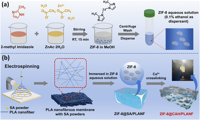
The synthesis process of ZIF-8 is shown in Fig. 1a. As illustrated, 2-methyl imidazole and zinc acetate synthesized ZIF-8 nanoparticles. The preparation process of ZIF-8@CAH/PLANF is presented in Fig. 1b and Fig. S1 (ESI†). The CAH/PLANF composite was obtained by spraying SA powders on electrospun PLA nanofibrous membranes formed by Ca2+ cross-linking. Meanwhile, the immersion of PLA in water made the nanofibers change from a densely packed 2-dimensional morphology to a swollen 3-dimensional morphology. This way, natural ECM was better mimicked by an interpenetrating network combined with the fibrous PLA and porous CA hydrogel. Benefiting from the ECM-like structure, a better cell growth and proliferation property can be realized as wound dressings.In particular, ZIF-8 powders were encapsulated into CAH/PLANF by intermolecular force before Ca2+ cross-linking to form the ZIF-8@CAH/PLANF composite patch. As proof, incorporating ZIF-8 into ZIF-8@CAH/PLANF is more helpful for the debridement and regulation of wound infection of the microbial colonized wounds especially. In addition, the mechanical properties of ZIF-8@CAH/PLANF can be further enhanced due to the presence of intermolecular force. Therefore, the ZIF-8@CAH/PLANF composite patch could present accelerated wound healing performance by combining good operational performance, exudate adsorption, biocompatibility, and anti-inflammatory effect.
The X-ray diffraction (XRD) pattern of ZIF-8 is illustrated in Fig. 2a, revealing the distinctive peaks of the prepared ZIF-8 sample and the corresponding theoretical simulation. The discernible elevation at 7.7° substantiates the successful synthesis of ZIF-8. Fig. 2b presents the Fourier transform infrared (FTIR) spectra of ZIF-8 powders, CAH/PLANF, and ZIF-8@CAH/PLANF. The characteristic peak of ZIF-8 at 3133 cm−1 corresponds to the vibrational stretching of N–H and C–H bonds in aliphatic and imidazole aromatic groups. Peaks at 1591 cm−1 and 1459 cm−1 are attributed to the stretching of the N–C bond in dimethyl imidazole and the stretching of the entire imidazole ring, respectively. Additionally, peaks at 1147 cm−1 and 702 cm−1 correspond to C–O oscillation and Zn–O forward and backward vibrations, affirming the successful synthesis of ZIF-8. Distinct peaks at 1742 cm−1, 1552 cm−1, and 1107 cm−1 in the FTIR spectra of CAH/PLANF represent characteristic features of PLA and SA. Notably, all these characteristic peaks are discernible in the FTIR results of ZIF-8@CAH/PLANF, providing further confirmation of the successful synthesis of ZIF-8@CAH/PLANF.20,21
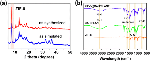 | ||
| Fig. 2 (a) The experimental ZIF-8 powder XRD patterns. (b) The ZIF-8, CAH/PLANF, and ZIF-8@CAH/PLANF FTIR spectra. | ||
3.2. Morphology and swelling properties of ZIF-8@CAH/PLANF
The morphologies of ZIF-8 powders, PLA nanofibers, and ZIF-8@CAH/PLANF were thoroughly examined using SEM, as depicted in Fig. 3. As illustrated in Fig. 3a, ZIF-8 displays a well-defined dodecahedral morphology with an average size of 300 nm, consistent with previous findings.18,25 Moving to Fig. 3b, SEM imaging reveals that PLA nanofibers exhibit a smooth surface with an approximate diameter of 300 nm. In Fig. 3c and d, SEM images showcase the successful generation of ZIF-8, densely scattered on the surface and pore walls of ZIF-8@CAH/PLANF. Furthermore, Fig. 3e and f demonstrate the successful integration of PLA nanofibers with calcium alginate hydrogel (CA), promising an enhancement in the mechanical properties of the composite. Notably, the immersion and absorption of water lead to some nanofibers exhibiting a coarser and swollen appearance, as highlighted in the images. The mapping spectra of zinc (Zn), carbon (C), oxygen (O), and nitrogen (N) were further investigated to show the dispersion of ZIF-8 in the hydrogel patch. The results in Fig. 3g showed that the four elements, especially zinc, could be found in the image, which indicated that ZIF-8 was uniformly dispersed in the ZIF-8@CAH/PLANF composite patch. Overall, the SEM results indicated the successful introduction of both PLA nanofibers and ZIF-8 into ZIF-8@CAH/PLANF has been completed.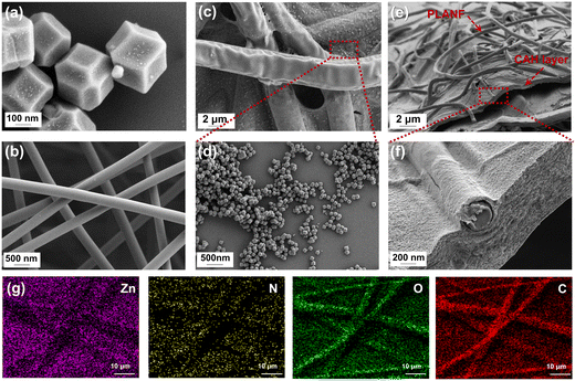 | ||
| Fig. 3 SEM images (a) utilization of ZIF-8 powders, (b) PLA nanofibers, and (c)–(f) freeze-dried ZIF-8@CAH/PLANF. (g) Mapping spectra of Zn, C, O, and N in ZIF-8 @CAH/PLANF. | ||
The swelling rate serves as a pivotal parameter in evaluating the wound exudate adsorption properties of wound dressings. To scrutinize the swelling characteristics, samples with a radius of 15 mm underwent freeze-drying and were subsequently immersed in 50 mL of PBS at room temperature. Each sample's weight was recorded until equilibrium. As shown in Fig. 4, CAH, CAH/PLANF, and ZIF-8@CAH/PLANF had an equilibrium absorbability capacity with swelling rates of 1272%, 1119%, and 1052%, respectively, after 330 min. It could be found that the swelling rates had decreased after introducing PLA nanofibers and ZIF-8. All samples that exhibited water uptake capacity benefited from hydrophilic materials and the interpenetrating porous network, illustrating that ZIF-8@CAH/PLANF could be an absorbing agent for wound exudates.
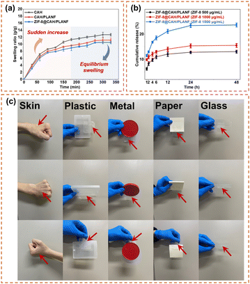 | ||
| Fig. 4 (a) The swelling ratio of CAH, CAH/PLANF, and CAH/PLANF. (b) Cumulative release ratio of ZIF-8@CAH/PLANF. (c) Adhesion test of ZIF-8@CAH/PLANF. | ||
3.3. Characterization of release behavior and adhesion of ZIF-8@CAH/PLANF
The results in Fig. 4b showed that the release rate of ZIF-8 remained relatively stable. The calculated cumulative release rates of ZIF-8 after 48 h in the ZIF-8@CAH/PLANF (500, 1000 and 1500 μg mL−1) groups were 13.08, 15.56, and 23.66%, respectively. The cumulative release amounts are essential to ZIF-8 contents in ZIF-8@CAH/PLANF.Particularly, it can be seen that the release of ZIF-8 was relatively quicker in the beginning period (the first 6 hours) and became slow after 24 h. It could be inferred the denser mesh-like composite structure of the ZIF-8@CAH/PLANF patch makes it more difficult for ZIF-8 to escape from the network compared with the pure hydrogel system in our previous study.10
The adhesion ability of the ZIF-8@CAH/PLANF composite patch was analyzed. In this experiment, the patch sample was attached to the surface of different solid materials. The results in Fig. 4c showed that the ZIF-8@CAH/PLANF patch could be adhered to human skin surfaces, plastic boxes, metal lips, paper, and glass, indicating that it has a good adhesion ability.
3.4. Mechanical properties
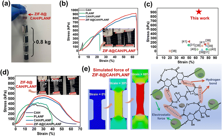
The basic requirement of an ideal wound dressing includes sufficient mechanical properties to maintain its structural integrity when in use. As shown in Fig. 5a, ZIF-8@CAH/PLANF had no damage under an external stretching force of 0.8 kg, indicating that the composites exhibited excellent tensile resistance. The results of the tensile test shown in Fig. 5b showed that the tensile breaking strength of ZIF-8@CAH/PLANF (891 kPa) was significantly higher than that of the PLA nanofibrous membrane (412 kPa) and pure CA hydrogel (199 kPa). CAH/PLANF and ZIF-8@CAH/PLANF samples had suitable stretchability, nearly 65% similar to human skin. Besides, compared to previous fiber-reinforced hydrogels, ZIF-8@CAH/PLANF also had excellent tensile properties (shown in Fig. 5c).31,38–42Given that dressings may encounter damage during use, additional assessment of tensile behavior was conducted using samples with a 0.5 cm defect, as depicted in the insets of Fig. 5d. The results illustrated in Fig. 5d indicate that within the tensile linear region (0–20%), CAH, CAH/PLANF, and ZIF-8@CAH/PLANF remained unaffected by the introduced defects. Fig. 5e (left panel) shows the simulated force of ZIF-8@CAH/PLANF using finite element analysis software (ANASY). In the tensile test, the results displayed the strain state of 0%, 30%, and 60%, respectively. The left image in Fig. 5e shows the tensile strength when stretching is uniformly distributed on ZIF-8@CAH/PLANF. The breaking point is mainly generated in the middle and lower part of the patch in the tensile test, which is consistent with the phenomenon in the actual experiment (insets in Fig. 5b). Actually, ZIF-8@CAH/PLANF exhibited excellent tensile properties even under the condition of defects because of physical and chemical enhancement. On the one hand, the introduction of nano or microfibers and ZIF-8 provided a physical reinforcement by constructing a 3D hierarchical structure (Fig. 3); on the other hand, hydrogen bond between CAH and PLANF and the electrostatic force between ZIF-8 and SA could further strengthen the interaction forces between components of the composite (right part in Fig. 5e). Therefore, compared to PLA nanofibrous membranes and pure CA hydrogel, the tensile stress of composites was obviously improved significantly for the ZIF-8@CAH/PLANF composite patch.
3.5. Antibacterial evaluation
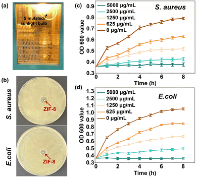
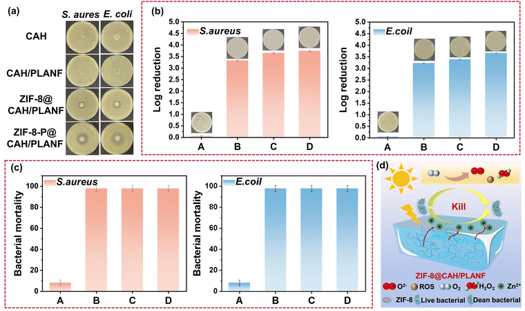
The photodynamic antibacterial activity of ZIF-8 was assessed against both Gram-negative E. coli and Gram-positive S. aureus. The experimental conditions for simulating sunlight are depicted in Fig. 6a. Typically, a light bulb with visible light (380–780 nm), illuminance of 41.4 W m−2 was packed into a constant temperature incubator to investigate the photocatalytic antibacterial properties of ZIF-8. The results in Fig. 6b showed a prominent bacteriostatic zone for ZIF-8 (1 mg), indicating that the bacteriostatic substance could be released by ZIF-8 successfully, thus making the surrounding bacteria die under the condition of light. Fig. 6c and d display the absorbance at 600 nm of bacterial suspensions mixed with ZIF-8 cultured under light at different times. A higher absorbance value indicated a higher bacterial concentration and a better bacterial reproduction behavior. As depicted in Fig. 6c and d, bacterial growth was significantly inhibited at a ZIF-8 concentration of 5000 μg mL−1, approaching negligible levels. Conversely, as the concentration of ZIF-8 decreased, the optical density at 600 nm (OD 600) gradually increased. This trend underscores the fact that the photocatalytic antibacterial efficacy of ZIF-8 is notably contingent on the concentration of ZIF-8.The antibacterial activities of the CAH, CAH/PLANF, and ZIF-8@CAH/PLANF were evaluated. CAH and CAH/PLANF exhibited no antibacterial effects. At the same time, ZIF-8@CAH/PLANF showed an apparent inhibition zone with or without light conditions, as shown in Fig. 7a. The bacterial mortality and log reduction were calculated to investigate the antibacterial activity quantitatively. As shown in Fig. 7b, ZIF-8@CAH/PLANF, at a concentration of 500 μg mL−1, exhibited a log colony-forming unit (CFU) reduction exceeding 3 for both E. coli and S. aureus, corresponding to a notable efficacy of over 99.9% (Fig. 7c). Moreover, in a photocatalytic environment, ZIF-8@CAH/PLANF (at a concentration of 500 μg mL−1) achieved a log CFU reduction surpassing 3.5 for both bacterial strains, demonstrating a promising efficacy exceeding 99.95%, which was at a relatively prominent antibacterial level (Table S1, ESI†). With an increase in the ZIF-8 concentration to 1000 μg mL−1, ZIF-8@CAH/PLANF achieved a log CFU reduction surpassing 4 for both E. coli and S. aureus, corresponding to a remarkable efficacy exceeding 99.99% in the photocatalytic environment. Fig. 7d elucidates the photocatalytic antibacterial mechanism of ZIF-8@CAH/PLANF. Cationic Zn2+ and antibacterial substances, including reactive oxygen, could be released from photocatalyzed ZIF-8, which inhibits bacterial growth and even kills bacteria. According to the results of the release behavior test (Fig. 4b), the released zinc ions could have an antibacterial effect. In contrast, the better antibacterial ability of ZIF-8-P@CAH/PLANF was more dominated by the photocatalysis antibacterial effect. In addition, based on the literature, it was found that the main difference in the antibacterial effect of ZIF-8 between light and no light conditions was reflected in the early stage.43 Besides, we have performed live and dead bacterial staining. The results in Fig. S2 (ESI†) showed that the dead bacteria (stained red) could be seen in each group, especially, the ZIF-8-P@CAH/PLA composite patch, which caused more bacteria to die, which further confirmed that the ZIF-8-P@CAH/PLA composite patch had a better and quicker antibacterial effect. Therefore, the encapsulation of ZIF-8 endows the ZIF-8@CAH/PLANF composite patch with faster and long-lasting photocatalytic antibacterial properties. Besides, after co-culture with ZIF-8@CAH/PLANF, the cell structure of E. coli and S. aureus was damaged, and internal substances flowed out of the bacterial cell membrane to shrink, disrupted the bacterial metabolism, damaged the structure and properties of the proteins in the bacterial cells, and finally killed the bacteria (Fig. S3, ESI†).
3.6. Cell culture and cytocompatibility evaluation
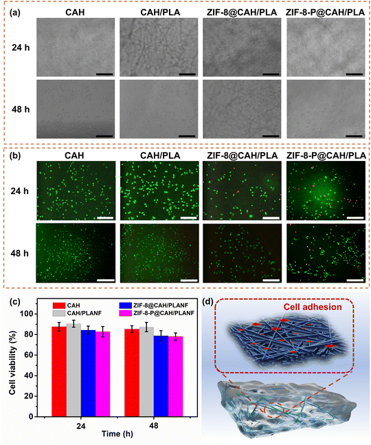
Generally, ideal wound dressings must have minimal toxicity to the human body. For this reason, L929 fibroblast cells were used to be cultured in the presence of CAH, CAH/PLANF, ZIF-8@CAH/PLANF, and photocatalytic ZIF-8@CAH/PLANF (labeled as ZIF-8-P@CAH/PLANF), respectively. Fig. 8a shows the images of the L929 fibroblast cells attached and proliferated on the sample surfaces after 24 and 48 hours. It could be seen that cells were attached to the surface of samples, and some were trapped inside the pores, especially in the presence of PLA nanofibrous membranes. Besides, the cell viability was evaluated by live/dead staining and quantitative MTS assay. Fig. 8b shows that the cells were almost stained green, and only a minimal number of cells are stained red in the groups of ZIF-8@CAH/PLANF and ZIF-8-P@CAH/PLANF, proving the low cytotoxicity of biocompatible ZIF-8. As shown in Fig. 8c, the survival rate of the cells cultured with the samples was basically higher than 80% and 75% after 24 h and 48 h, respectively, which further confirmed the excellent biocompatibility of all samples. Overall, ZIF-8@CAH/PLANF acted as wound dressings to simulate the structure of ECM better and provided an ideal bionic environment for cell growth and adhesion; L929 cells could be adhered both on the surface and in the pores of CA and PLA.3.7. Wound healing performance
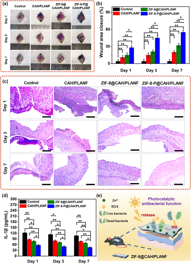
The in vivo wound healing process using CAH/PLANF, ZIF-8@CAH/PLANF, and ZIF-8@CAH/PLANF as an S. aureus infected full-thickness wound model evaluated wound dressings. As depicted in Fig. 9a, evident paleness and persistent injury sites were observed in the control group even after seven days. This observation suggests that the untreated wounds had undergone an extended period of inflammation and healing. It could be found that the wounds in the CAH/PLANF and ZIF-8@CAH/PLANF groups showed a better healing condition compared with the control group, with less paleness and smaller wound areas. In contrast, the healing process of the wound treated with ZIF-8@CAH/PLANF was significantly accelerated, and there was no apparent dark scar in this group. After being treated for a week, as shown in Fig. 9b, the wound area closure in control, CAH/PLANF, ZIF-8@CAH/PLANF, and ZIF-8-P@CAH/PLANF groups was 4.1%, 20.4%, 32.1%, and 55.9%, respectively. In Fig. 9c, a considerable reduction in the interleukin 1β (IL-1β) values was observed in the sample groups, with the ZIF-8-P@CAH/PLANF group displaying the least inflammatory response—the histopathological analysis (H&E) shown in Fig. 9c. As shown in Fig. 9d, on the first day, examination revealed initial defects in the epidermal and dermal layers across all groups. By the third day, varying degrees of inflammation was observed, with the control group displaying the most prominent infiltration of inflammatory cells, particularly neutrophils stained in blue. After seven days, defects in the ZIF-8-P@CAH/PLANF group showed partial replacement by collagen fibers.44,45 These in vivo results substantiate the effectiveness of the ZIF-8@CAH/PLANF composite patch in promoting wound healing. The mechanism of ZIF-8@CAH/PLANF for wound healing is presented in Fig. 9e. As a wound dressing, ZIF-8@CAH/PLANF with good biocompatibility not only temporarily replaces skin to block external contamination but also exhibits combined properties of water permeability, absorbing excess tissue fluid. Moreover, being encapsulated with ZIF-8 as a durable photocatalytic antibacterial material by releasing ROS, hydrogen peroxide, oxygen ions, and other antibacterial substances, ZIF-8@CAH/PLANF has an excellent wound healing effect by reducing bacterial infection.4. Conclusions
A hydrogel/nanofiber composite patch with an interpenetrated network was constructed. The composite has the ability to absorb water, manage wound tissue fluid, mechanical strength, and cell compatibility. Photocatalytic ZIF-8 powders were mainly synthesized and encapsulated into the hydrogel/nanofiber for bacterial infection. The ZIF-8@CAH/PLANF composite patch showed better performance in healing bacterial infection wounds. All these results indicate that ZIF-8@CAH/PLANF has an ideal therapeutic effect in the healing of bacteria-infected wounds and may be a promising candidate for promoting wound healing.Author contributions
Hongju Cheng: investigation and writing – original draft. Md All Amin Newton: methodology and writing – review & editing. Rajib Mia: investigation. Qinchen Zhang: investigation. Weihong Gao: investigation. Zan Lu: investigation. Yuansheng Zheng: conceptualization and supervision. Zijian Dai: conceptualization, supervision, and writing – review & editing. Jie Zhu: conceptualization, supervision, and writing – review & editing.Conflicts of interest
The authors declare that they have no known competing financial interests or personal relationships that could have appeared to influence the work reported in this paper.Acknowledgements
This research was funded by the National Natural Science Foundation of China (Grant no. 52103051) and the Shanghai Sailing Program (Project no. 21YF1415700).Notes and references
- K. Zhang, X. Jiao, L. Zhou, J. Wang, C. Wang, Y. Qin and Y. Wen, Biomaterials, 2021, 276, 121040 CrossRef CAS PubMed.
- M. Deng, M. Zhang, R. Huang, H. Li, W. Lv, X. Lin, R. Huang and Y. Wang, Biomaterials, 2022, 289, 121790 CrossRef CAS PubMed.
- X.-Y. Chen, Y. Wang, S.-Q. Ma, Y.-Q. Huang, W. Jing, P.-F. Wei, X.-Q. Yu and B. Zhao, J. Mater. Chem. B, 2022, 10, 6279–6286 RSC.
- S. Jiang, S. Liu, S. Lau and J. Li, J. Mater. Chem. B, 2022, 10, 7239–7259 RSC.
- Z. Liu, K. Guo, L. Yan, K. Zhang, Y. Wang, X. Ding, N. Zhao and F.-J. Xu, Nat. Commun., 2023, 14 Search PubMed.
- K. Zha, W. Zhang, W. Hu, M. Tan, S. Zhang, Y. Yu, S. Gou, P. Bu, B. Zhou, Y. Zou, Y. Xiong, B. Mi, G. Liu, Q. Feng and K. Cai, Adv. Funct. Mater., 2024, 34, 2308145 CrossRef CAS.
- Y. Yang, M. Li, G. Pan, J. Chen and B. Guo, Adv. Funct. Mater., 2023, 33 Search PubMed.
- H. Xu, F. Zhang, M. Wang, H. Lv, D. G. Yu, X. Liu and H. Shen, Biomater. Adv., 2022, 136, 212795 CrossRef CAS PubMed.
- C. Guo, Y. Wang, H. Liu, Y. Wu, Y. Wang, Z. Cao, W. Li, Y. Peng, H. Xiong, B. Jin, Q. Kong and J. Wu, Mater. Des., 2022, 224 Search PubMed.
- J. Zhu, F. Li, X. Wang, J. Yu and D. Wu, ACS Appl. Mater. Interfaces, 2018, 10, 13304–13316 CrossRef CAS PubMed.
- L. Feng, Q. Chen, H. Cheng, Q. Yu, W. Zhao and C. Zhao, Adv. Healthcare Mater., 2022, 11 Search PubMed.
- J. Zhu, H. Han, F. Li, X. Wang, J. Yu, X. Qin and D. Wu, Chem. Mater., 2019, 31, 4436–4450 CrossRef CAS.
- W. Dan, M. Zeng, B. Su, Y. Zhang, K. Wu, T. Zhou, C. Wu, J. Sun and H. Fan, J. Mater. Chem. B, 2023, 11, 6567–6580 RSC.
- J. Zhu, H. Han, T.-T. Ye, F.-X. Li, X.-L. Wang, J.-Y. Yu and D.-Q. Wu, Molecules, 2018, 23 CAS.
- Z. Shao, G. Kang, J. Xie, R. Shen, H. Li, Z. Zeng, J. Jiang, X. Wang, W. Li, S. Guo, Y. Liu and G. Zheng, Sep. Purif. Technol., 2023, 327 Search PubMed.
- J. Qian, Q. Dong, K. Chun, D. Zhu, X. Zhang, Y. Mao, J. N. Culver, S. Tai, J. R. German, D. P. Dean, J. T. Miller, L. Wang, T. Wu, T. Li, A. H. Brozena, R. M. Briber, D. K. Milton, W. E. Bentley and L. Hu, Nat. Nanotechnol., 2022, 18, 168–176 CrossRef PubMed.
- J. Zhu, W. Qiu, C. Yao, C. Wang, D. Wu, S. Pradeep, J. Yu and Z. Dai, J. Colloid Interface Sci., 2021, 603, 243–251 CrossRef CAS PubMed.
- H. Li, Z. Qin, X. Yang, X. Chen, Y. Li and K. Shen, ACS Cent. Sci., 2022, 8, 718–728 CrossRef CAS PubMed.
- B. Zhang, H. Chen, Q. Hu, L. Jiang, Y. Shen, D. Zhao and Z. Zhou, Adv. Funct. Mater., 2021, 31 Search PubMed.
- Z. Mo, D. Tai, H. Zhang and A. Shahab, Chem. Eng. J., 2022, 443 Search PubMed.
- Y. Song, N. Wang, L.-Y. Yang, Y. G. Wang, D. Yu and X.-K. Ouyang, Ind. Eng. Chem. Res., 2019, 58, 6394–6401 CrossRef CAS.
- Y.-B. Hao, Z.-S. Shao, C. Cheng, X.-Y. Xie, J. Zhang, W.-J. Song and H.-S. Wang, ACS Appl. Mater. Interfaces, 2019, 11, 31755–31762 CrossRef CAS PubMed.
- Y. Zou, J. Weng, Z. Qin, Y. Zhang, S. Ji and H. Zhang, Chem. Eng. J., 2023, 473 Search PubMed.
- Y. N. Reddy, A. De, S. Paul, A. K. Pujari and J. Bhaumik, Biomacromolecules, 2023, 24, 1717–1730 CrossRef CAS PubMed.
- V. A. Tran, A. N. Kadam and S. W. Lee, J. Alloys Compd., 2020, 835, 155414 CrossRef CAS.
- P. Li, J. Li, X. Feng, J. Li, Y. Hao, J. Zhang, H. Wang, A. Yin, J. Zhou, X. Ma and B. Wang, Nat. Commun., 2019, 10 CrossRef PubMed.
- X. Yao, G. Zhu, P. Zhu, J. Ma, W. Chen, Z. Liu and T. Kong, Adv. Funct. Mater., 2020, 30 Search PubMed.
- X. Cai, L. Gao, J. Wang and D. Li, ACS Appl. Mater. Interfaces, 2023, 15, 8537–8545 CrossRef CAS PubMed.
- M. Zakerikhoob, S. Abbasi, G. Yousefi, M. Mokhtari and M. S. Noorbakhsh, Carbohydr. Polym., 2021, 271, 118434 CrossRef CAS PubMed.
- X. Liu, L. Gao, S. Fu, W. Zhao, F. Wang, J. Gao, C. Li, H. Wu and L. Wang, Mater. Des., 2023, 227 Search PubMed.
- Q. Zhang, J. Zhu, S. Jin, Y. Zheng, W. Gao, D. Wu, J. Yu and Z. Dai, Mater. Lett., 2022, 323 CAS.
- J. Xiong, A. Li, Y. Liu, L. Wang, X. Qin and J. Yu, Small, 2022, 18, e2105570 CrossRef PubMed.
- D. Lv, R. Wang, G. Tang, Z. Mou, J. Lei, J. Han, S. De Smedt, R. Xiong and C. Huang, ACS Appl. Mater. Interfaces, 2019, 11, 12880–12889 CrossRef CAS PubMed.
- X. Lu, X. Li, J. Yu and B. Ding, Acta Biomater., 2022, 154, 49–62 CrossRef CAS PubMed.
- C. Wang, X. Song, T. Li, X. Zhu, S. Yang, J. Zhu, X. He, J. Gao and H. Xu, ACS Appl. Mater. Interfaces, 2023, 15, 37580–37592 CrossRef CAS PubMed.
- M. Tang, L. Jiang, C. Wang, X. Li, X. He, Y. Li, C. Liu, Y. Wang, J. Gao and H. Xu, ACS Appl. Mater. Interfaces, 2023, 15, 25919–25931 CrossRef CAS PubMed.
- X. Cheng, T. Li, L. Yan, Y. Jiao, Y. Zhang, K. Wang, Z. Cheng, J. Ma and L. Shao, Sci. Adv., 2023, 9, eadh8195 CrossRef CAS PubMed.
- M. Chen, H. Wan, Y. Hu, F. Zhao, X. An and A. Lu, Mater. Horiz., 2023, 10, 4510–4520 RSC.
- Z. Chen, H. Zhang, C. Fan, Y. Zhuang, W. Yang, Y. Chen, H. Shen, Z. Xiao, Y. Zhao, X. Li and J. Dai, ACS Nano, 2022, 16, 1986–1998 CrossRef CAS PubMed.
- L. Gao, X. Liu, W. Zhao, C. Li, F. Wang, J. Gao, X. Liao, L. Wei, H. Wu, Y. Zheng and L. Wang, Biofabrication, 2022, 15 Search PubMed.
- X. Lu, Y. Si, S. Zhang, J. Yu and B. Ding, Adv. Funct. Mater., 2021, 31 Search PubMed.
- J. Tang, J. Li, J. J. Vlassak and Z. Suo, Extreme Mech. Lett., 2017, 10, 24–31 CrossRef.
- T. T. Li, H. Zhang, B. Gao, B. C. Shiu, H. T. Ren, H. K. Peng, C. W. Lou and J. H. Lin, Chem. Eng. J., 2021, 422, 130007 CrossRef CAS.
- W. Xie, J. Chen, X. Cheng, H. Feng, X. Zhang, Z. Zhu, S. Dong, Q. Wan, X. Pei and J. Wang, Small, 2023, 19, 2205941 CrossRef CAS PubMed.
- X. Cheng, X. Pei, W. Xie, J. Chen, Y. Li, J. Wang, H. Gao and Q. Wan, Small, 2022, 18, 2200915 CrossRef CAS PubMed.
Footnote |
| † Electronic supplementary information (ESI) available. See DOI: https://doi.org/10.1039/d3tb02683c |
| This journal is © The Royal Society of Chemistry 2024 |

