Co-doped MnS/NiS/Ni3S2 grown in situ on hydrophilic nickel foam for energy-efficient urea-assisted alkaline hydrogen production†
Haojie
Ma
 ab,
Muzaffar Ahmad
Boda
 a,
Yang
Zhou
a,
Chenhao
Shi
a and
Zhiguo
Yi
a,
Yang
Zhou
a,
Chenhao
Shi
a and
Zhiguo
Yi
 *a
*a
aState Key Lab of High Performance Ceramics and Superfine Microstructure, Shanghai Institute of Ceramics, Chinese Academy of Sciences, Shanghai 201899, China. E-mail: zhiguo@mail.sic.ac.cn
bSchool of Materials Science and Engineering, Shanghai University, Shanghai 200444, China
First published on 7th May 2024
Abstract
The electrochemical oxidation of urea provides a promising pathway for hydrogen production with a theoretically reduced energy consumption of 93% lower than water electrolysis. Therefore, designing efficient bifunctional non-noble metal-based electrocatalysts capable of catalyzing both urea oxidation reaction and hydrogen evolution reaction are important. Herein, a Co-doped MnS/NiS/Ni3S2 catalyst with a complex structure of nanoparticles and nanosheets simultaneously grown on a 3D hydrophilic nickel foam (HNF) was prepared via electrodeposition and a two-step hydrothermal method. The resulting catalyst (Co-MnS/NiS/Ni3S2/HNF) exhibited a remarkable performance as a self-supported bifunctional electrode for UOR and HER, requiring overpotentials of only 1.313 V at 50 mA cm−2 and 34 mV at 10 mA cm−2, respectively. At a high current density of 100 mA cm−2, an overpotential of only 1.343 V was required for UOR, which is about 202 mV lower than OER carried in 1 M KOH to achieve the same current density. Further, the performance of the electrocatalyst showed no apparent deterioration in the 96 h stability test for HER and UOR. Furthermore, we designed an alkaline electrolytic cell with the bifunctional Co-MnS/NiS/Ni3S2/HNF catalyst, which compared to the traditional electrolytic cell for water splitting (OER‖HER) showed a reduction in voltage by 300 mV, driving a current density of 100 mA cm−2 at only 1.75 V in 1 M KOH + 0.33 M urea. The faradaic efficiency of hydrogen production was calculated to be about 100%. Overall, this work provides a new paradigm in the design of efficient bifunctional non-noble metal-based electrocatalysts for HER and UOR in alkaline media.
1. Introduction
Clean and cost-effective sustainable electrocatalytic water splitting technology for hydrogen (H2) production is often considered the most promising way to resolve the problem of fossil energy consumption and environmental pollution in future energy systems.1–4 However, it requires high energy consumption due to the sluggish kinetics of oxygen evolution reaction (OER) occurring on the anode side, hindering the electrolysis of water.5–7 Thus, to overcome this limitation, sacrificial agent oxidation reactions (SAORs) have been proposed as alternatives to OER.8,9 Among them, urea oxidation reaction (UOR, CO(NH2)2 + 6OH− → N2 + 5H2O + CO2 + 6e−) with a low theoretical potential of 0.37 V versus the reversible hydrogen electrode (RHE) is one of the ideal replacements, enabling a theoretical energy saving of ≈70%.10–15 In addition, the use of urea-containing wastewater in UOR further demonstrates its significance.14,16–18 Nevertheless, the complexity of UOR is a challenge, including its sluggish kinetics due to its six-electron transfer process, which requires the use of highly active catalysts to promote the reaction rate.19–21 In this case, although noble metal (such as Pt,11 Ru22 and Rh23)-based catalysts exhibit high catalytic activity for UOR and HER, future large-scale energy systems demand alternative catalysts with low cost, high reserves and high catalytic performance. Accordingly, the development of bifunctional non-noble metal-based electrocatalysts that can act as both efficient anodic UOR and cathodic HER catalysts will simplify the system and reduce the production costs. However, achieving this remains a major challenge.Nickel-based electrocatalysts are considered as a promising alternative to noble metal-based catalysts considering their low cost, competitive electrocatalytic activity and excellent catalytic stability, and thus have broad application prospects in urea-assisted water splitting for H2 production.24–28 In recent years, various strategies, such as interface engineering, defect engineering, and heteroatom doping, have been applied to simultaneously improve the interfacial charge transfer kinetics and active surface area of catalysts to enhance their catalytic activity.22,29,30 The heterointerface effect can integrate the active centers of different components to form multi-site reaction pathways for promoting the cleavage of the HO–H bond and accelerate the Volmer step.14,31,32 Chen et al.33 reported that a nanowire-like Ni3S2@NiS heterojunction structure on NF only required a overpotential of 129 mV to achieve a current density of 10 mA cm−2 in alkaline HER. Due to the strong charge transfer at the heterogeneous junction of Ni3S2/NiS, the d-band center of the catalyst showed a favorable downward shift, which optimized the valence state of Ni and the free energy of adsorbed H intermediates on the active site. Additionally, doping trace elements in catalysts is another effective strategy for enhancing the catalytic properties for UOR. The synergy caused by the strong interaction between the dopant atoms and the active sites optimizes the adsorption and desorption energy of the intermediates.34–37 Furthermore, a self-supported electrode (such as Ni foam), which supports the catalytically active phases grown in situ, optimizes the electrode preparation process, reduces the interfacial resistance, exposes a higher density of active sites, and improves the overall stability of the catalyst.25,38
Herein, a Co-MnS/NiS/Ni3S2 catalyst with a complex structure of nanoparticles and nanosheets simultaneously etched on hydrophilic nickel foam (Co-MnS/NiS/Ni3S2/HNF) was prepared via electrodeposition and the hydrothermal method. Based on the super-hydrophilicity of HNF, heterogeneous interface of MnS, NiS and Ni3S2, and Co doping, the self-supported Co-MnS/NiS/Ni3S2/HNF catalyst showed an excellent electrochemical performance for both HER and UOR in alkaline media. In the case of HER, an overpotential of only 34 and 178 mV was required to achieve a current densities of 10 mA cm−2 and 100 mA cm−2, respectively. In the electrocatalytic UOR in 1 M KOH + 0.33 M urea, a low overpotential of 1.313 V was required drive a current density of 50 mA cm−2 and a high current density of 100 mA cm−2 was achieved at an overpotential of only 1.343 V, which is about 202 mV lower than OER performed in 1 M KOH to gain the same current density. Furthermore, the catalytic performance of the electrocatalyst did not deteriorate significantly in the long-time stability test for 96 h at 100 mA cm−2 (HER and UOR). Furthermore, the coupled HER‖UOR system in the two-electrode configuration exhibited exceptional durability, delivering 100 mA cm−2 at a low cell voltage of only 1.75 V, which shifted negatively by 300 mV compared to the conventional HER‖OER coupled system. Moreover, the faradaic efficiency of hydrogen production was calculated to be about 100%. This work presents a novel method for preparing a highly active doped electrocatalyst, which can be used in the field of energy-efficient hydrogen production and water splitting-assisted urea wastewater treatment.
2. Experimental
2.1. Materials and chemicals
Nickel(II) chloride hexahydrate (NiCl2·6H2O), ammonium chloride (NH4Cl), cobalt(II) nitrate hexahydrate (Co(NO3)2·6H2O) and thioacetamide (C2H5NS, TAA) were commercially purchased from Adamas-Beta Co., Ltd. Potassium permanganate (KMnO4), potassium hydroxide (KOH) and urea were provided by Shanghai Titan Technology Co., Ltd. Acetone and absolute ethyl alcohol were purchased from Shanghai Lingfeng Chemical Reagent Co., Ltd. Nickel rods were purchased from Qinghe Bolton Cemented Carbide Co., Ltd. All reagents were of analytical grade (A.R.) and used without further purification. Nickel-foam was purchased from Shenzhen Kejing Co., Ltd.2.2. Synthesis of HNF
Initially, NF (size: 1 cm × 1.5 cm) was cleaned sequentially in deionized water, acetone, anhydrous ethanol, deionized water, 3 M HCl and deionized water under ultrasonication for 20 min. Then, HNF was prepared via the electrodeposition method, where a mixed solution of 0.1 M NiCl2·6H2O and 2 M NH4Cl was used as the electrolyte, and NF and a nickel rod were used as the working and counter electrodes, respectively. The electrodeposition was carried at a current density of −1.0 A cm−2 for 1000 s to preparate HNF, and then cleaned with deionized water and anhydrous ethanol and dried in an electric thermostatic drying oven at 50 °C for 6 h.2.3. Synthesis of Co-MnS/NiS/Ni3S2/HNF
Co-MnS/NiS/Ni3S2/HNF was prepared via a two-step hydrothermal method. In the first step, 2.5 mmol of KMnO4 and 1 mmol of Co(NO3)2·6H2O were dissolved in 40 mL of deionized water under vigorous stirring for 30 min, and then transferred to a 100 mL Teflon-lined autoclave. Subsequently, two HNF precursors were immersed in the solution, and then the autoclave was kept at 100 °C for 16 h to obtain Co-MnO2/NiMnO3/HNF. After cooling to room temperature, its surface was treated with deionized water and ethanol. Subsequently, it was dried in an electric thermostatic drying oven at 50 °C for 12 h. In the second step, 2 mmol TAA was dissolved in 40 mL of deionized water under magnetic stirring. Then two pieces of Co-MnO2/NiMnO3/HNF and a homogeneous aqueous solution were transferred to a 100 mL Teflon container, which was subsequently kept at 120 °C for 8 h. After cooling to room temperature, the samples were cleaned with anhydrous ethanol and deionized water, and then dried in an electric thermostatic drying oven at 50 °C for 12 h. A similar method was used for the synthesis of the MnS/Ni3S2/HNF precursor but without the addition of Co(NO3)2·6H2O, and similarly the Ni3S2/HNF precursor was obtained without the addition of KMnO4 and Co(NO3)2·6H2O.Detailed information regarding the material characterizations and electrochemical measurement parameters is provided in the ESI.†
3. Results and discussion
3.1. Synthesis and structural characterization
Fig. 1a illustrates the step-wise procedure used to prepare Co-MnS/NiS/Ni3S2/HNF on the NF. Initially, 3D porous and super-hydrophilic HNF was electrodeposited on the smooth surface of NF, which provided a larger surface area and nickel source for the subsequent hydrothermal reaction. Next, the surface of HNF was etched by the oxidizing agent of KMnO4 in the hydrothermal step to prepare Co-MnO2/NiMnO3/HNF, the formation of which was clearly confirmed by the X-ray diffraction peaks corresponding to MnO2 (JCPDS no. 72-1982), NiMnO3 (JCPDS no. 75-2089) and Ni (JCPDS no. 04-0850), as shown in Fig. 1b. Moreover, Co doping could affect the process of HNF etching by MnO4− and form a special morphology. Subsequently, Co-MnS/NiS/Ni3S2/HNF was converted to Co-MnO2/NiMnO3/HNF after the sulfidation reaction with TAA. In the XRD test (Fig. 1c), the XRD pattern of Co-MnS/NiS/Ni3S2/HNF was found to perfectly match the combination of MnS (JCPDS no. 40-1289), NiS (JCPDS no. 40-1289), Ni3S2 (JCPDS no. 44-1418) and Ni. The diffraction peaks at 2θ = 21.75°, 31.10°, 37.77° and 38.27° can be assigned to the (101), (110), (003) and (021) crystal planes of the Ni3S2 phase and the peaks at 2θ = 25.81°, 27.63°, 29.34° and 45.56° correspond to the (100), (002), (101) and (110) planes of the MnS phase, respectively. Meanwhile, the diffraction peaks located at 18.45°, 32.25°, 35.77° and 50.02° belong to the (110), (300), (021) and (410) planes of the NiS crystal, whereas the peaks at 44.49°, 51.84° and 76.38° can be assigned to the (111), (200) and (220) planes of the Ni crystal, respectively. However, no peaks corresponding to Co were detected, which is presumed to be doped in the form of ions in the material. In the comparative analysis, the XRD patterns of the Co-MnS/NiS/Ni3S2/HNF, MnS/Ni3S2/HNF and Ni3S2/HNF catalysts, as shown in Fig. S1,† showed the presence of Co2+, which contributed to the appearance of the NiS phase.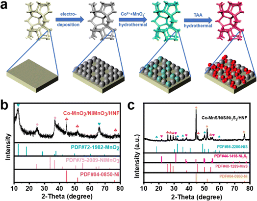 | ||
| Fig. 1 Schematic illustration of the preparation of the Co-MnS/NiS/Ni3S2/HNF electrocatalyst (a). XRD patterns of Co-MnO2/NiMnO3/HNF (b) and Co-MnS/NiS/Ni3S2/HNF (c). | ||
Scanning electron microscopy (SEM) revealed the transformation of the morphology of NF upon the deposition of HNF, Co-MnO2/NiMnO3/HNF, and then vulcanization to prepare Co-MnS/NiS/Ni3S2/HNF. Before deposition, the surface of NF was very smooth (Fig. S2(a–c)†). However, after the deposition of HNF with cauliflower-like microstructures (Fig. S2(d–f)†), its surface became rough, porous and hydrophilic, which provided a large surface area and nickel source for the subsequent hydrothermal reaction. Afterwards, in the first step of hydrothermal synthesis, in situ etching of HNF by MnO4− and Co2+ created cracks in the HNF particles and roughened their surface (Fig. S2(g–i)†). As the transformation progressed, the surface of HNF became rougher, indicating the generation of more complex multilevel structures. This structure implies that Co-MnS/NiS/Ni3S2/HNF possessed a higher specific surface area and more exposed heterogeneous interfaces or activated sites, which are significant for improving the catalytic activity of catalysts. However, a more intricate Co-MnS/NiS/Ni3S2/HNF hybrid array appeared after the further vulcanization of Co-MnO2/NiMnO3/HNF. As shown in Fig. 2a–c, the cracked surface layer transformed into small particles. The vulcanization process exposed the underlying rough, porous and hydrophilic HNF surface with cauliflower-like microstructures. The elemental mappings of Co-MnS/NiS/Ni3S2/HNF (Fig. S3a†) obtained from the corresponding EDS spectrum (Fig. S3b†) revealed the uniform distribution of Ni, Mn, Co and S, and the presence of 23 wt% of Co confirmed that Co was doped in MnS/NiS/Ni3S2 in the form of ions. Compared to MnS/Ni3S2/HNF and Co-MnS/NiS/Ni3S2/HNF, the addition of Co element changed the surface morphology from a polygonal nanocolumn to nanoparticle (Fig. S4c† and 2c).
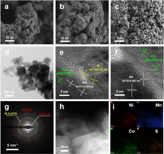 | ||
| Fig. 2 SEM images (a–c), TEM image (d), HRTEM images (e and f), SAED pattern (g), HAADF-STEM image (h) and EDX mappings images (i) of the Co-MnS/NiS/Ni3S2/HNF catalyst. | ||
The microstructural analysis of the Co-MnS/NiS/Ni3S2/HNF catalyst was further carried by transmission electron microscopy (TEM). As shown in Fig. 2d, the microstructure of Co-MnS/NiS/Ni3S2/HNF consisted of nanoparticles and nanosheets, of which the lattice fringes (Fig. 2e and f) with interplanar spacings of 2.38 Å, 3.04 Å, 4.80 Å and 2.03 Å correspond to the (003), (101), (110) and (111) planes of Ni3S2, MnS, NiS and Ni, respectively. The selected-area electron diffraction (SAED) pattern shown in Fig. 2g further validates the above-mentioned results for the existence of Ni3S2 and NiS in Co-MnS/NiS/Ni3S2/HNF. The EDX mapping shown in Fig. 2h–i for Co-MnS/NiS/Ni3S2/HNF shows the uniform distribution of Ni, Mn, Co, and S elements on the catalyst surface. The complex structure of coexisting nanoparticles and nanosheets is significant for increasing the contact area between the electrode and electrolyte, and consequently enhancing the utilization of the active sites.
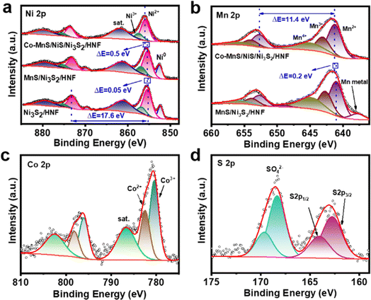
The compositions, valence states and electronic interaction of Co-MnS/NiS/Ni3S2/HNF, MnS/Ni3S2/HNF and Ni3S2/HNF were further probed via X-ray photoelectron spectroscopy (XPS). As shown in Fig. S5,† the presence of Ni, Mn, Co, O, S and C elements in the full spectrum is in good agreement with the EDS results. The presence of O may be due to the surface oxidation of the catalyst when exposed to air.39 In the Ni 2p spectrum (Fig. 3a) of Co-MnS/NiS/Ni3S2/HNF, the two pair of peaks for Ni 2p3/2 (856.0 eV) and 2p1/2 (873.6 eV) and Ni 2p3/2 (857.3 eV) and Ni 2p1/2 (875.4 eV) are ascribed to Ni2+ and Ni3+, respectively. The two weaker peaks located at 854.5 eV and 871.9 eV are attributed to Ni0, and the peaks at 861.8 eV and 879.7 eV correspond to the satellite peaks.2,39,40 According to Fig. 3a, the energy gap between the two peaks of Ni2+ was determined to be 17.6 eV. Compared to MnS/Ni3S2/HNF and Ni3S2/HNF, the slight positive shift in the Ni2+ signal (0.5 eV and 0.55 eV) in Co-MnS/NiS/Ni3S2/HNF may be due to the presence of strong electronic interactions among MnS, NiS and Ni3S2, indicating that the addition of Co had a positive effect on the reaction between MnO4− and Ni. The XPS spectrum of Mn 2p includes two spin–orbit splitting components of 2p1/2 and 2p3/2 with satellite peaks. As shown in Fig. 3b, the Mn 2p spectrum of Co-MnS/NiS/Ni3S2/HNF could be deconvoluted into four pair of peaks, as follows: (I) peaks at 641.2 eV (for Mn 2p3/2) and 652.7 eV (for Mn 2p1/2), corresponding to Mn2+, (II) peaks at 643.0 eV (for Mn 2p3/2) and 653.9 eV (for Mn 2p1/2), which are associated with Mn3+, (III) peaks at 645.1 eV (for Mn 2p3/2) and 656.0 eV (for Mn 2p1/2) corresponding to Mn4+, and (IV) two peaks at 638.5 eV and 649.4 eV, corresponding to metal Mn.40 The energy gap between the two peaks of Mn2+ is 11.4 eV. Compared to MnS/Ni3S2/HNF, the slight positive shift (0.2 eV) in the Mn 2p3/2 signal for Co-MnS/NiS/Ni3S2/HNF may be due to the existence of electronic interactions between NiS and MnS. The Co 2p spectrum of Co-MnS/NiS/Ni3S2/HNF shows the third spin–orbit doublets of Co3+ (780.4 eV of Co 2p3/2 and 796.0 eV of Co 2p1/2), Co2+ (782.5 eV of Co 2p3/2 and 798.1 eV of Co 2p1/2) and satellite peaks (786.7 eV and 802.5 eV) (Fig. 3c).41 In the S 2p spectrum, the peaks at 162.7 eV and 164.1 eV can be ascribed to S 2p3/2 and 2p1/2 of S2− species in Co-MnS/NiS/Ni3S2/HNF, while the other bands at 168.3 eV and 169.6 eV are attributed to the sulfate species formed by the further oxidation of the sulfide ions (Fig. 3d).32,41 Thus, based on the XRD and XPS results, it can be verified that Co was successfully incorporated in the lattice of MnS, NiS and Ni3S2 in Co-MnS/NiS/Ni3S2/HNF.
3.2. Electrochemical HER activities
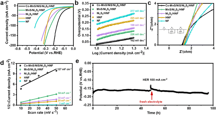
The electrocatalytic performance of the as-prepared electrocatalysts for the HER was evaluated in alkaline solution (1.0 M KOH) with the standard three-electrode system at a scan rate of 5 mV s−1. For comparison, the electrochemical tests of all the prepared catalysts were assessed under the same conditions. The LSV polarization curves of the as-prepared electrocatalysts indicate that Co-MnS/NiS/Ni3S2/HNF has an excellent HER performance. As shown in Fig. 4a and S6,† the lowest overpotential of 34 mV and 178 mV was required to reach the current density of 10 mA cm−2 and 100 mA cm−2, respectively. These values are lower than that of the MnS/Ni3S2/HNF (67 mV and 245 mV), Ni3S2/HNF (99 mV and 203 mV), HNF (149 mV and 286 mV) and NF (188 mV and 410 mV) electrocatalysts, respectively. Besides, the Tafel slopes were plotted from the polarization curves to gain further insight into the HER reaction kinetics of the different electrocatalysts under alkaline conditions. As shown in Fig. 4b, the Tafel slope for Co-MnS/NiS/Ni3S2/HNF is 162 mV dec−1, which is smaller than that of MnS/Ni3S2/HNF (226 mV dec−1), Ni3S2/HNF (198 mV dec−1), HNF (225 mV dec−1) and NF (277 mV dec−1), demonstration its optimized HER kinetics.Subsequently, electrochemical impedance spectroscopy (EIS) was performed to further explore the interfacial properties of the as-prepared electrocatalysts. The Nyquist plots and the corresponding equivalent circuit diagram are shown in Fig. 4c, where Rs is the solution resistance, Rct is the charge transfer resistance between the catalyst and the electrolyte, R2 is the diffusion of the reactive species in the catalyst layer, and CPE represents the constant-phase element. The Rct value of Co-MnS/NiS/Ni3S2/HNF is 40.6 mΩ, which is much lower than that of MnS/Ni3S2/HNF (235.0 mΩ), Ni3S2/HNF (168.0 mΩ) and HNF (127.0 mΩ), indicating its excellent charge transfer kinetics at the catalyst/electrolyte interface during the HER. Finally, to gain insights into the reason for the excellent HER activity of Co-MnS/NiS/Ni3S2/HNF, its double-layer capacitance (Cdl) was measured to estimate its electrocatalytic active surface area (ECSA) using CV curve measurements in the non-faradaic potential range. As shown in Fig. 4d and S7,† the calculated Cdl value of Co-MnS/NiS/Ni3S2/HNF is 127.0 mF cm−2, which is higher than that of MnS/Ni3S2/HNF (59.0 mF cm−2), Ni3S2/HNF (30.0 mF cm−2), and NF (1.0 mF cm−2). Thus, the results show that Co-MnS/NiS/Ni3S2/HNF has the largest electrochemical surface area and most exposed active sites for HER.
The long-term stability of the Co-MnS/NiS/Ni3S2/HNF catalyst was evaluated by a long-term chronopotentiometry test (100 mA cm−2 @ 96 h), where the electrolyte was replaced at 48 h intervals to reduce the experimental error (Fig. 4e). The electrochemical stability of the Co-MnS/NiS/Ni3S2/HNF electrode towards HER was confirmed by its high overpotential retention after continuous operation for 96 h at a current density of 100 mA cm−2. The results indicate that Co-MnS/NiS/Ni3S2/HNF has good stability and catalytic activity, outperforming previously reported comparable catalysts, as summarized in Table S1.†
To gain a deeper understanding of the changes in Co-MnS/NiS/Ni3S2/HNF after the stability test, we conducted further analysis of its surface elements and morphology by SEM and corresponding elemental mappings, respectively (Fig. S8†). It can be seen from the SEM images in Fig. S8(a and b)† that the morphology of the Co-MnS/NiS/Ni3S2/HNF catalyst changed from its original nanoparticle structure to a lamellar structure, which was clustered after the stability test. This indicates that most of the nanoparticles on the catalyst surface were carried away by strong hydrogen bubbles in the reaction process, exposing the lamellar structure on the surface. Moreover, the EDS elemental mapping clearly confirmed the presence of Ni, Mn, Co and S elements in the catalyst (Fig. S8(d–f)†), confirming its excellent stability. The surface chemical constituents of Co-MnS/NiS/Ni3S2/HNF after the stability measurement were investigated by XPS (Fig. S9†). Which revealed that the chemical composition and valence state of the elements did not change significantly before and after the chronopotentiometry measurement. The XRD analysis (Fig. S10†) also revealed that there was no significant difference in the phase change of Co-MnS/NiS/Ni3S2/HNF after HER compared with the original catalyst, manifesting that the superior HER stability of the electrode can be attributed to the intrinsic properties of Co-MnS/NiS/Ni3S2/HNF.
3.3. Electrochemical UOR activities
Given that the concentration of urea in human urine is ca. 2–2.5 wt% (≈0.33 M), the electrochemical catalytic properties of the as-prepared catalysts were evaluated in 1 M KOH with 0.33 M urea. As shown in Fig. 5a and S11,† the Co-MnS/NiS/Ni3S2/HNF catalyst showed a low potential of 1.313 V to drive a current density of 50 mA cm−2 for the electrocatalytic UOR. The high current density of 100 mA cm−2 was achieved at an overpotential of only 1.343 V, which is about 202 mV lower than that for OER performed in 1 M KOH to gain the same current density. Compared with the traditional OER process, it can be notably observed that after 0.33 M urea was introduced in the system, the anodic current density remarkably increased in the low potential range, indicating that the oxidation of urea on the Co-MnS/NiS/Ni3S2/HNF electrode was significantly more favorable than that of OER, indicating its best UOR performance among the as-prepared catalysts.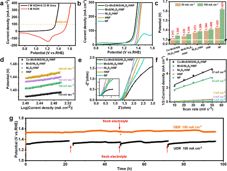 | ||
| Fig. 5 Polarization curves of Co-MnS/NiS/Ni3S2/HNF in 1 M KOH with and without 0.33 M urea (a). UOR LSV curves with iR-compensation (b), voltages required for samples to reach different current densities in UOR (obtained from Fig. 4a) (c), Tafel plots (d), Nyquist plots (e) and electrochemical double-layer capacitance of scan rate in the range of 10 mV s−1 to 50 mV s−1 (f) for Co-MnS/NiS/Ni3S2/HNF, MnS/Ni3S2/HNF, Ni3S2/HNF, HNF and NF in 1 M KOH containing 0.33 M urea. Chronopotentiometry curves of Co-MnS/NiS/Ni3S2/HNF at a constant current density of 100 mA cm−2 for OER and UOR, respectively (g). | ||
The UOR activity was evaluated by an LSV test, and the results indicated that Co-MnS/NiS/Ni3S2/HNF exhibited the best performance among the samples (Fig. 5b and c). The Tafel slopes were calculated to elucidate their kinetics for UOR. As shown in Fig. 5d, Co-MnS/NiS/Ni3S2/HNF demonstrated a Tafel slope of 135 mV dec−1, which is lower than that of MnS/Ni3S2/HNF (188 mV dec−1), Ni3S2/HNF (142 mV dec−1) and HNF (182 mV dec−1), evidencing its favorable kinetics. These results prove that Co-MnS/NiS/Ni3S2/HNF exhibited superior activity, which ranks among the best-reported urea electrocatalysis systems (Table S2†).
The electrochemical impedance spectroscopy (EIS) data for the electrocatalysts were also compared. According to the Nyquist plots (Fig. 5e), Co-MnS/NiS/Ni3S2/HNF showed a smaller Rct of 228 mΩ than MnS/Ni3S2/HNF (336 mΩ), Ni3S2/HNF (408 mΩ) and HNF (6.65 Ω) for UOR. The Cdl values estimated from the CV curves were also applied to evaluate the electrochemical active surface area (ECSA) in UOR (Fig. 5f). The results showed that Co-MnS/NiS/Ni3S2/HNF has the largest Cdl value, which means it has the most abundant surface catalytic active sites among the electrocatalysts. Besides its excellent UOR activity, the electrochemical stability of Co-MnS/NiS/Ni3S2/HNF was further assessed with chronopotentiometry. As shown in Fig. 5g, the required voltage value gradually increased with the consumption of urea, but the catalytic performance of Co-MnS/NiS/Ni3S2/HNF remained consistent after the replacement of the electrolyte (electrolyte replaced every 24 h). Similarly, Co-MnS/NiS/Ni3S2/HNF also showed excellent catalytic stability in OER.
3.4. Catalytic activity toward overall electrolysis
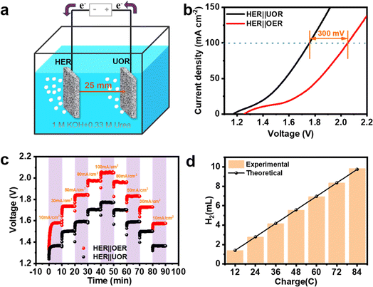
Given its excellent bifunctional electrocatalytic activity towards both UOR and HER, a hydrogen production device with energy-saving properties was assembled using Co-MnS/NiS/Ni3S2/HNF as the two electrodes (Fig. 6a and S12†). As experimentally proven in Fig. 6b, the urea-aided water electrolysis exhibited more favorable overall performances including lower cell voltage and reduced energy consumption. In particular, Co-MnS/NiS/Ni3S2/HNF displayed lower cell voltages of only 1.29 V, 1.57 V and 1.75 V in urea-assisted alkaline water splitting for achieving current densities of 10 mA cm−2, 50 mA cm−2 and 100 mA cm−2, respectively. Compared to OER, the voltage required for UOR to reach a current density of 100 mA cm−2 was about 300 mV lower. As exhibited in Fig. 6c, the multi-step chronopotentiometry plot started at the current density region of 10–100 mA cm−2 (10, 30, 50, 80 and 100 mA cm−2). The working potential exhibited fast feedback after the change in current density and remained stable during each 600 s process, simultaneously illustrating the fast mass/charge transfer ability of the Co-MnS/NiS/Ni3S2/HNF electrocatalyst. In addition, as shown in Fig. 6d, the faradaic efficiency of hydrogen production was calculated to be about 100%, demonstrating the enormous potential of Co-MnS/NiS/Ni3S2/HNF. Based on these comprehensive advantages, Co-MnS/NiS/Ni3S2/HNF can be considered a promising self-supporting electrode for energy-efficient hydrogen production.4. Conclusion
In conclusion, the Co-MnS/NiS/Ni3S2/HNF heterostructure electrocatalyst was successfully constructed via the electrodeposition and two-step hydrothermal methods. The high oxidizing ability of MnO4− was used to in situ etch HNF to obtain MnS and Ni3S2. The addition of Co2+ promoted the emergence of the NiS phase and changed the surface of the catalyst from polyhedral columns to the complex morphology of nanoparticles and nanosheets. The element Co existed as Co2+ ions in MnS/NiS/Ni3S2. The self-supporting Co-MnS/NiS/Ni3S2/HNF catalyst showed an excellent electrochemical performance for both HER and UOR in alkaline media, which could remarkably enhance the catalytic activity and catalytic stability at low and high current densities. The Co-MnS/NiS/Ni3S2/HNF catalyst required the lowest overpotential of 34 mV and 178 mV to reach the current density of 10 mA cm−2 and 100 mA cm−2 for HER, respectively. Also, it showed a low potential of 1.313 V to drive a current density of 50 mA cm−2 for the electrocatalytic UOR in 1 M KOH + 0.33 M urea and a high current density of 100 mA cm−2 was achieved at a potential of only 1.343 V, which was about 202 mV less to gain the same current density compared to the OER performed in 1 M KOH. The performance of the electrocatalyst did not deteriorate significantly after the stability test of 100 mA cm−2 @ 96 h (HER and UOR). Furthermore, the coupled HER‖UOR system in the two-electrode configuration exhibited exceptional durability, delivering 100 mA cm−2 at an ultralow cell voltage of only 1.75 V, which shifted negatively by 300 mV compared to the conventional HER‖OER coupled system. Moreover, the faradaic efficiency of hydrogen production was calculated to be about 100%. This work provides a promising avenue for developing high-performance catalysts for energy-efficient hydrogen production.Author contributions
Haojie Ma: conceptualization, data curation, formal analysis, investigation, methodology, writing – original draft, writing – review & editing. Muzaffar Ahmad Boda: conceptualization, investigation, supervision, writing – review & editing. Young zhou: formal analysis, investigation. Chenhao shi: formal analysis, investigation. Zhiguo Yi: funding acquisition, project administration, writing – review & editing.Conflicts of interest
There are no conflicts to declare.Acknowledgements
This work was financially supported by the National Natural Science Foundation of China (Grant No. 52372130, 52202152 and 51872311), the Natural Science Foundation of Shanghai (Grant No. 19ZR1464900), and the Frontier Science Key Project of the Chinese Academy of Sciences (QYZDB-SSW-JSC027). The authors would like to thank Shiyanjia Lab for their support of SEM, TEM and XPS testing as well (https://www.shiyanjia.com/).Notes and references
- W. Liu, W. Xu, G. Dong and M. Fang, Nanomaterials, 2023, 13, 2268 CrossRef CAS PubMed.
- Y. Xiong, L. Xu, C. Jin and Q. Sun, Appl. Catal., B, 2019, 254, 329–338 CrossRef CAS.
- K. Wu, Y. Niu, N. Liu, C. Lyu, H. Li, P. Hu, X. Zhu, B. Jia, W.-M. Lau and J. Zheng, Catal. Today, 2023, 424, 113852 CrossRef CAS.
- X. Fan, B. Li, C. Zhu, F. Yan, X. Zhang and Y. Chen, Small, 2024, 2309655 CrossRef PubMed.
- X. Xu, H. Liao, L. Huang, S. Chen, R. Wang, S. Wu, Y. Wu, Z. Sun and H. Huang, Appl. Catal., B, 2024, 341, 123312 CrossRef CAS.
- H. Zhao, M. Liu, X. Du and X. Zhang, Int. J. Hydrogen Energy, 2024, 58, 117–127 CrossRef CAS.
- Y. Zhou, J. Zhou, M. A. Boda, K. Zhao, H. Ma, C. Shi, D. Yuan and Z. Yi, Sustainable Energy Fuels, 2024, 8, 957–963 RSC.
- S. Zhang, M. Jin, H. Xu, X. Zhang, T. Shi, Y. Ye, Y. Lin, L. Zheng, G. Wang, Y. Zhang, H. Yin, H. Zhang and H. Zhao, Energy Environ. Sci., 2024, 17, 1950–1960 RSC.
- J. Liu, S. C. Smith, Y. Gu and L. Kou, Adv. Funct. Mater., 2023, 33, 2305894 CrossRef CAS.
- Y. Li, H. Guo, Y. Zhang and R. Song, Appl. Catal., B, 2024, 341, 123296 CrossRef CAS.
- M. Zhong, M. Xu, S. Ren, W. Li, C. Wang, M. Gao and X. Lu, Energy Environ. Sci., 2024, 17, 1984–1996 RSC.
- V. M. Zemtsova, A. G. Oshchepkov and E. R. Savinova, ACS Catal., 2023, 13, 13466–13473 CrossRef CAS.
- S. W. Tatarchuk, J. J. Medvedev, F. Li, Y. Tobolovskaya and A. Klinkova, Angew. Chem., Int. Ed., 2022, 61, e202209839 CrossRef CAS PubMed.
- H. Ding, Z. Zhao, H. Zeng, X. Li, K. Cui, Y. Zhang and X. Chang, ACS Mater. Lett., 2024, 6, 1029–1041 CrossRef CAS.
- C. Wang, Q. Wang, X. Du and X. Zhang, Dalton Trans., 2023, 52, 13161–13168 RSC.
- W. Yan, D. Wang and G. G. Botte, Appl. Catal., B, 2012, 127, 221–226 CrossRef CAS.
- Z.-H. Zhang, Z.-R. Yu, Y. Zhang, A. Barras, A. Addad, P. Roussel, L.-C. Tang, M. Naushad, S. Szunerits and R. Boukherroub, J. Mater. Chem. A, 2023, 11, 19578–19590 RSC.
- P. Li, Y. Wang, X. Du and X. Zhang, Dalton Trans., 2023, 52, 10499–10506 RSC.
- X. Liu, K. Deng, P. Liu, X. Lv, W. Tian, K. Ma, H. Li and J. Ji, Appl. Catal., B, 2024, 343, 123470 CrossRef CAS.
- J. Yu, Z. Li, C. Wang, X. Xu, T. Liu, D. Chen, Z. Shao and M. Ni, J. Colloid Interface Sci., 2024, 661, 629–661 CrossRef CAS PubMed.
- B. Feng, W. Jiang, R. Deng, J. Lu, P. Tsiakaras and S. Yin, J. Colloid Interface Sci., 2024, 663, 1019–1027 CrossRef CAS PubMed.
- Y. Liu, H. Li, X. Liu, Y. Wang, L. Wang, T. Yang, A. R. Jadhav, J. Zhang, Y. Wang, M. Wu, J. Y. Lee, M. G. Kim and H. Lee, ACS Nano, 2023, 18, 874–884 CrossRef PubMed.
- B. Zhang, Y. Zheng, Z. Xing, Z. Wu, C. Cheng, T. Ma and S. Li, J. Mater. Chem. A, 2024, 12, 4484–4491 RSC.
- K. Wu, C. Lyu, J. Cheng, Z. Guo, H. Li, X. Zhu, W.-M. Lau and J. Zheng, Small, 2023, 20, 2304390 CrossRef PubMed.
- M. Liu, W. Zou, S. Qiu, N. Su, J. Cong and L. Hou, Adv. Funct. Mater., 2024, 34, 2310155 CrossRef CAS.
- Z. Zeng, W. Zhao, S. Yuan, Y. Dong, J. Zhu, F. Jiang, Y. Yang, S. Liu, L. Wang and P. Ge, ACS Appl. Energy Mater., 2022, 5, 9189–9213 CrossRef CAS.
- N. Qu, L. Han, T. Wu, Q. Luo, S. Tang, J. Gu, D. Wang and A. Kareiva, Coatings, 2023, 13, 1938 CrossRef CAS.
- Y. Cao, T. Wang, X. Li, L. Zhang, Y. Luo, F. Zhang, A. M. Asiri, J. Hu, Q. Liu and X. Sun, Inorg. Chem. Front., 2021, 8, 3049–3054 RSC.
- A. M. Shah, K. H. Modi, P. M. Pataniya, K. S. Joseph, S. Dabhi, G. R. Bhadu and C. K. Sumesh, ACS Appl. Mater. Interfaces, 2024, 16, 11440–11452 CrossRef CAS PubMed.
- T. L. L. Doan, D. C. Nguyen, K. Kang, A. Ponnusamy, H. I. Eya, N. Y. Dzade, C. S. Kim and C. H. Park, Appl. Catal., B, 2024, 342, 123295 CrossRef.
- P. Guo, S. Cao, W. Huang, X. Lu, W. Chen, Y. Zhang, Y. Wang, X. Xin, R. Zou, S. Liu and X. Li, Adv. Mater., 2024, 2311766 CrossRef CAS PubMed.
- K. Zhang, Y. Duan, N. Graham and W. Yu, Appl. Catal., B, 2023, 323, 122144 CrossRef CAS.
- M. Chen, Q. Su, N. Kitiphatpiboon, J. Zhang, C. Feng, S. Li, Q. Zhao, A. Abudula, Y. Ma and G. Guan, Fuel, 2023, 331, 125794 CrossRef CAS.
- S. Xu, X. Ruan, M. Ganesan, J. Wu, S. K. Ravi and X. Cui, Adv. Funct. Mater., 2024, 202313309 Search PubMed.
- Y. Gong, Y. Lin, Z. Yang, F. Jiao, J. Li and W. Wang, Appl. Surf. Sci., 2019, 476, 840–849 CrossRef CAS.
- W. Jiang, X. Zhuo, T. Yu, J. Lu, Z. Zhai, H. Wen and S. Yin, ACS Sustainable Chem. Eng., 2024, 12, 998–1006 CrossRef.
- Y. Feng, N. Ran, X. Wang, Q. Liu, J. Wang, L. Liu, K. Suenaga, W. Zhong, R. Ma and J. Liu, Adv. Energy Mater., 2023, 13, 2302452 CrossRef CAS.
- R. Andaveh, A. Sabour Rouhaghdam, A. Seif, K. Wang, M. Maleki, J. Ai, G. Barati Darband and J. Li, ACS Appl. Mater. Interfaces, 2024, 16, 8717–8732 CrossRef CAS PubMed.
- X. Tong, Y. Li, Q. Ruan, N. Pang, Y. Zhou, D. Wu, D. Xiong, S. Xu, L. Wang and P. K. Chu, Adv. Sci., 2022, 9, 2104774 CrossRef CAS PubMed.
- Y. Zhang, J. Fu, H. Zhao, R. Jiang, F. Tian and R. Zhang, Appl. Catal., B, 2019, 257, 117899 CrossRef CAS.
- Y. Sun, J. Wang, Y. Qi, W. Li and C. Wang, Adv. Sci., 2022, 9, 2200957 CrossRef CAS PubMed.
Footnote |
| † Electronic supplementary information (ESI) available. See DOI: https://doi.org/10.1039/d4se00442f |
| This journal is © The Royal Society of Chemistry 2024 |

