 Open Access Article
One-pot hydrothermal synthesis of molybdenum nickel sulfide with graphene quantum dots as a novel conductive additive for enhanced supercapacitive performance†
Omkar
Sangabathula
 * and
Chandra S.
Sharma
Creative & Advanced Research Based on Nanomaterials (CARBON) Laboratory, Department of Chemical Engineering, Indian Institute of Technology, Hyderabad, Kandi 502285, Telangana, India. E-mail: ch18resh01007@iith.ac.in
First published on 16th September 2020
Abstract
We depict a facile as well as an economical one-step hydrothermal method, for the first time, to synthesize a hierarchical three-dimensional (3D) flower-like structure of molybdenum (Mo) particle decorated nickel sulfide and its composite with graphene quantum dots (GQDs) for high-performance supercapacitor applications. An optimum coupling of GQDs with Mo doped nickel sulfide (MNS-G) enhances the electrical conductivity further by creating more active sites and thus helps in modulating the electrochemical behavior of the composite. The prepared MNS-G-2.5 composite (2.5 wt% GQD) exhibits a superior specific capacitance of 2622 F g−1 at 1 A g−1 and shows an excellent coulombic efficiency of 92.2% after 10![[thin space (1/6-em)]](https://www.rsc.org/images/entities/char_2009.gif) 000 cycles at a current density as high as 20 A g−1. The fabricated aqueous-based asymmetric supercapacitor device exhibits an excellent energy density of 38.9 W h kg−1 at a power density of 416.6 W kg−1 with an impressive capacitance retention and coulombic efficiency of 96.4% and 95.9%, respectively, after 10
000 cycles at a current density as high as 20 A g−1. The fabricated aqueous-based asymmetric supercapacitor device exhibits an excellent energy density of 38.9 W h kg−1 at a power density of 416.6 W kg−1 with an impressive capacitance retention and coulombic efficiency of 96.4% and 95.9%, respectively, after 10![[thin space (1/6-em)]](https://www.rsc.org/images/entities/char_2009.gif) 000 charge–discharge cycles. These outstanding electrochemical properties of GQD- and molybdenum-incorporated nickel sulfide pave the way for the development of efficient electrode materials for practical supercapacitor applications.
000 charge–discharge cycles. These outstanding electrochemical properties of GQD- and molybdenum-incorporated nickel sulfide pave the way for the development of efficient electrode materials for practical supercapacitor applications.
Introduction
With ever increasing per capita energy consumption and the alarming depletion of fossil fuels worldwide, the scientific community is committed to finding better solutions in terms of high-performance energy storage devices. Supercapacitors play a predominant role in the area of energy storage devices due to their advantages such as a long cyclic stability, fast charge/discharge cycles, excellent reversibility, and profound power density values.1–4 One of the deterministic factors deciding the performance of supercapacitors is the selection of a suitable kind of electrode material which includes metal oxides, sulfides, and phosphates.5–7 Even though, among metal sulfides, nickel sulfide (Ni3S2) has a great potential due to its high theoretical capacitance, better redox reversibility, morphological flexibility, and environmental friendliness, because of the poor electrical conductivity of nickel sulfides, their actual specific capacitance values are way less than the theoretical value and they also show less cyclic stability, which limit their practical application.8–14 To overcome these limitations, one of the strategies is to use conductive substrates like nickel foam, carbon cloth, and metal sheet, over which the direct growth of these composite materials like nickel sulfides may take place, which in turn helps in improving the poor electrical conductivity.15–19 Another strategy is the incorporation of higher electrical conductivity materials like metals into the Ni3S2 structure, which will result in the formation of more active sites.20,21 Using conductive substrates, we may also synthesize these electrodes as binder-free with crystalline morphology, but it does not improve the internal conductivity of the material. Furthermore, in order to elevate the electrochemical performance of metal doped nickel sulfides, various forms of carbon-based nanomaterials may also be embedded, which not only provides stability to the electrode materials but also helps in the regulation of the internal structures during long cyclic stability tests.22–27 Recently, among various carbon nanomaterials, graphene quantum dots (GQDs) have drawn serious attention, especially in the fields of sensors, luminescence, bioimaging probes, and energy storage. These GQDs have an sp2 hybridized carbon, which resembles the structural framework of graphene along with 0D structures with a diameter of 1–20 nm. Taking advantage of the higher specific surface areas and tunable bandgaps, and having the benefit of doping various heteroatoms, GQDs are probing a new and effective pathway towards the development of robust materials having better electrochemical properties.28–35 There are some recent studies on the effect of GQD inclusion on different types of metal oxides/sulfides for supercapacitor applications.36–39 The synergistic effect is one of the major factors that contribute to the enhanced electrochemical performance of electrodes, whereas transition metal sulfides doped with metals take advantage from each component because nickel and molybdenum sulfides provide richer redox chemistry compared to the corresponding individual binary sulfides, which possess a higher theoretical capacity. To the best of our knowledge, we are the first to report the effect of GQD inclusion on molybdenum doped nickel sulfide (MNS) for supercapacitor applications in a binder-free approach. GQD- and molybdenum-incorporated nickel sulfide (MNS-G) was prepared on nickel foam by a single step facile hydrothermal synthesis method. The insertion of molybdenum created more active sites with the combination of structural stability from GQDs and the synergistic effect of double metal ions. The unique 3D flower morphology and the synergistic effect from both metal ions further improve fast ion migration and provide a short diffusion path for the electrolyte, resulting in good performance. The as prepared MNS-G exhibited a high surface area and three-dimensional (3D) flower-like morphology with an excellent ultra-high specific capacitance of 2622 F g−1 at 1 A g−1 while the pristine MoNiS (MNS) sample exhibited a specific capacitance of 1915 F g−1 at 1 A g−1. Moreover, an asymmetric supercapacitor was fabricated using reduced graphene oxide (rGO) as the negative electrode and MNS-G-2.5 as the positive electrode, which delivered a profound coulombic efficiency and a superior capacity retention of 95.9% and 96.4% at 2 A g−1, respectively. The improved electrochemical performance provides a new dimension for researchers working towards the development of high-performance supercapacitors for practical applications.Experimental section
Materials
Nickel foam was purchased from MTI Corp., USA. Ammonium heptamolybdate tetrahydrate ((NH4)6Mo7O24·4H2O), thiourea (CH4N2S), urea (CH4N2O) and citric acid (C6H8O7) were purchased from Sigma-Aldrich and used as received. Hydrochloric acid and ethanol were purchased from Hychem Laboratories.Ni foam pre-treatment
To remove the oxide layer on the surface, the as obtained nickel foam was ultra-sonicated for 30 minutes in a 3 M HCl solution and washed thoroughly with DI water and then in ethanol three times each; it was then vacuum-dried at 60 °C for 12 hours.GQD preparation
The procedure for the hydrothermal synthesis of GQDs is as follows. Firstly, 360 mg of urea and 420 mg of citric acid were added into 10 ml of DI water and stirred continuously for 45 minutes to obtain a homogeneous mixture. Later, the solution was transferred to a 50 ml autoclave and kept at 160 °C for 4 hours. After the cooling of the autoclave, the GQDs were centrifuged and kept at 80 °C for drying.Synthesis of MNS and MNS-G compounds
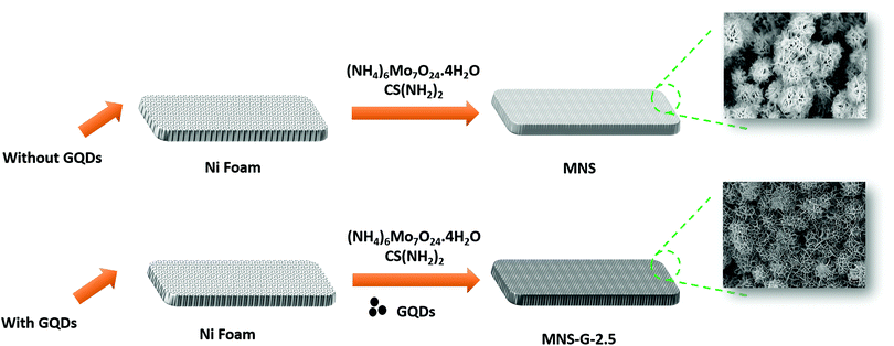
A one-step hydrothermal synthesis technique was used to prepare the binder-free MNS and MNS-G composites as shown in Fig. 1. A mixed solution of ammonium heptamolybdate tetrahydrate (121 mg), thiourea (38 mg), and a certain amount of GQDs was added into 60 ml of DI water and stirred for 30 minutes to form a homogeneous solution. Later the pre-treated Ni foam (6 cm × 1 cm) was added to the solution, and the precursor solution was transferred to a 100 ml autoclave, which was then placed in a muffle furnace at 180 °C for 12 hours. After completion of natural cooling, the precursor grown Ni foam was cleaned with DI water and ethanol thoroughly and vacuum-dried at 60 °C for 12 hours. The same hydrothermal conditions were used in the preparation of the only MNS samples, except for the addition of GQDs into the solution. The specific mass loadings of the samples on Ni foam for MNS-G-2.5 and MNS were 2.9 and 1.4 mg cm−2, respectively.To achieve an enhanced capacitance from the MNS-G composites and to study the effect of the electrochemical performance of GQDs on MNS composites, the amount of GQD loading (1, 2, 2.5, 5 and 10 mg) during the hydrothermal synthesis was varied and are labelled as MNS-G-n, where n represents the loading of GQDs in mg.
Materials characterization
The crystal structures of the MNS and MNS-G-n composites were characterized using X-ray diffraction (XRD) (PANalytical, Cu-Kα radiation with λ = 1.5406 Å). A WITec alpha300 Raman system equipped with a 532 nm laser was used for Raman characterization. FESEM (ZEISS ULTRA FEG55) and HRTEM (JEOL JEM 2100) were used to examine the surface morphology of the prepared MNS and MNS-G-n composites. BET analysis was carried out using a Micromeritics ASAP 2020 analyzer and then the specific surface area was calculated using a multi-point Brunauer–Emmett–Teller (BET) equation. Fourier transform-infrared (FT-IR) analysis was performed using a Tensor 37 system (Bruker, USA).Electrochemical measurements
The electrochemical characterizations were performed using an Autolab 302-N potentiostat in a conventional three-electrode set-up in a 3 M KOH electrolyte. The prepared MNS and the MNS-G-2.5 composite grown on Ni foam were used as the binder free working electrodes, whereas Ag/AgCl (KCl solution) and Pt sheet were (1 × 1 cm2) used as the reference and counter electrodes, respectively. To evaluate the electrochemical performance of the prepared composite, cyclic voltammetry (CV) and galvanostatic charge–discharge (GCD) tests were performed from 5 mV s−1 to 200 mV s−1 and 1 A g−1 to 20 A g−1, respectively. The cyclic stability of the composite was examined using a repetitive GCD test at 20 A g−1. Electrochemical impedance spectroscopy (EIS) analysis was conducted in the frequency range of 0.01 Hz to 100 kHz at open circuit potential with a 5 mV amplitude.Later, the asymmetric supercapacitor (ASC) device was fabricated by using MNS-G-2.5 as the positive electrode and rGO as the negative electrode and tested for electrochemical performance in a 3 M KOH electrolyte, which is named MNS-G-2.5//rGO ASC.
The mass-specific capacitance, Cm (F g−1), was calculated from the GCD curves by using the following eqn (1):
| Cm = (I × t)/(m × ΔV) | (1) |
The energy density E (W h kg−1) and power density P (W kg−1) of the fabricated ASC device were calculated using eqn (2) and (3), respectively:
| E = 1/2CV2 | (2) |
| P = E/t | (3) |
Results and discussion
Materials characterization
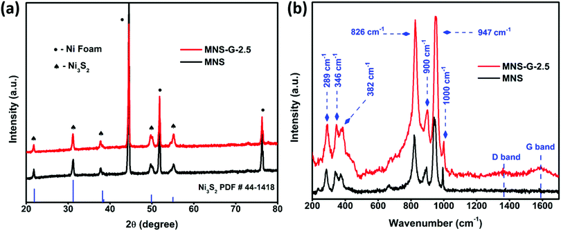
Fig. 2a shows the XRD patterns of MNS and the MNS-G-2.5 composite. From the high-intensity XRD peaks, we can confirm the crystalline structure of the compound. For the MNS sample, the peaks at the 2![[thin space (1/6-em)]](https://www.rsc.org/images/entities/char_2009.gif) theta values of 21.7°, 31.1°, 37.8°, 49.7°, and 55.1° correspond to the (101), (110), (003), (113) and (122) planes of Ni3S2 (JCPDS 44-1418), which are also in good agreement with the results reported for Ni3S2 in the literature,40,41 whereas the three sharp peaks at 44.5°, 51.8° and 76.2° belong to Ni-foam (JCPDS 11-0099). For the MNS-G-2.5 composite, Ni3S2 and Ni foam peaks are prominent. There are no other additional peaks present, which confirms the phase purity of the formed compound. The addition of molybdenum atoms and GQDs does not have an adverse effect on the Ni3S2 crystal structure.42 The enlarged view of the XRD pattern (Fig. S1a, ESI†) shows that the peaks of Ni3S2 shifted slightly to the lower two theta side. It is because of the addition of molybdenum with a larger ion size, which results in an increase in the lattice parameters of Ni3S2. Meanwhile, no additional peaks are observed for GQDs, which may be because of their lower diffraction intensity and content.43 The XRD patterns of MNS-G-1, MNS-G-2, MNS-G-5, and MNS-G-10 are shown in Fig. S1b (ESI†), where the pure phase of Ni3S2 is present without additional peaks, which indicates the purity of the composites formed.
theta values of 21.7°, 31.1°, 37.8°, 49.7°, and 55.1° correspond to the (101), (110), (003), (113) and (122) planes of Ni3S2 (JCPDS 44-1418), which are also in good agreement with the results reported for Ni3S2 in the literature,40,41 whereas the three sharp peaks at 44.5°, 51.8° and 76.2° belong to Ni-foam (JCPDS 11-0099). For the MNS-G-2.5 composite, Ni3S2 and Ni foam peaks are prominent. There are no other additional peaks present, which confirms the phase purity of the formed compound. The addition of molybdenum atoms and GQDs does not have an adverse effect on the Ni3S2 crystal structure.42 The enlarged view of the XRD pattern (Fig. S1a, ESI†) shows that the peaks of Ni3S2 shifted slightly to the lower two theta side. It is because of the addition of molybdenum with a larger ion size, which results in an increase in the lattice parameters of Ni3S2. Meanwhile, no additional peaks are observed for GQDs, which may be because of their lower diffraction intensity and content.43 The XRD patterns of MNS-G-1, MNS-G-2, MNS-G-5, and MNS-G-10 are shown in Fig. S1b (ESI†), where the pure phase of Ni3S2 is present without additional peaks, which indicates the purity of the composites formed.
Fig. 2b presents the Raman spectra of MNS and MNS-G-2.5 on Ni foam. The Raman peaks at 289 cm−1, 346 cm−1, and 382 cm−1 can be assigned to the Ni3S2 phase,44 and the Raman bands at 826 cm−1, 900 cm−1, 947 cm−1, and 1000 cm−1 correspond to the orthorhombic MoO3 phase in the MNS sample.45 Interestingly the MNS-G-2.5 sample retains all the characteristic peaks from the MNS sample with two additional peaks at 1350 cm−1 and 1589 cm−1, which are indicative of the D and G bands of carbon. These two additional peaks at 1350 cm−1 and 1589 cm−1 in MNS-G-2.5 indicate the successful incorporation of GQDs into the MNS matrix. Fig. S2 (ESI†) shows the Raman spectrum of only GQD sample that signifies the typical graphitic features of D mode (∼1360 cm−1) arising due to the symmetry breaking at edges and defects46 and the G-band (∼1585 cm−1) that can be assigned to in-plane carbon–carbon deformations. Furthermore, an ID/IG ratio of 0.78 as calculated confirms the rich graphitic content in the GQDs.47
Fig. 3 shows the surface morphologies of MNS and the MNS-G-2.5 composite. The FESEM image of GQDs reveals the agglomerated spherical interconnected particles (Fig. S3, ESI†), whereas the MNS sample reveals the fascinating self-organized 3D flower-like morphology with an average flower size of 6.19 μm grown on Ni foam (Fig. 3a-c). MNS-G-2.5 shows a well maintained 3D flower-like morphology with a decrease in the size of a flower (4.37 μm) because of the inclusion of GQDs into the Ni3S2 matrix (Fig. 3d–e), which can be related to the other compounds.48–50 Importantly, this 3D flower-like morphology of Ni3S2 is reported for the first time, to the best of our knowledge. Fig. 3f shows the enlarged view of the 3D flower of the MNS-G-2.5 sample. It can be clearly observed that the orientation of stacks of petals, which are interconnected with a thickness of ∼45–80 nm, resulted in a 3D flower-like structure through an Ostwald ripening phenomenon.51 Such a novel 3D architecture results in the creation of enormous space and contact for the electrolyte ions, which ultimately favours the electrochemical performance of the MNS-G-2.5 composite, as discussed later. The compositional analysis of the MNS-G-2.5 composite analyzed using energy dispersive X-ray spectrometry (EDS) is shown in Fig. S4 (ESI†). The EDS spectrum of the composite shows the presence of Mo, Ni, S, C, and O elements with a carbon content of 2 wt%, which confirms the successful synthesis of the MNS-G composite. In addition, the elemental mapping of MNS-G-2.5 shown in Fig. S5 (ESI†) reveals the uniform distribution of the elements all over the composite. Interestingly the distribution of Mo element is almost the same as that of S element which manifests that Ni3S2 sheets and Mo elements grow together.
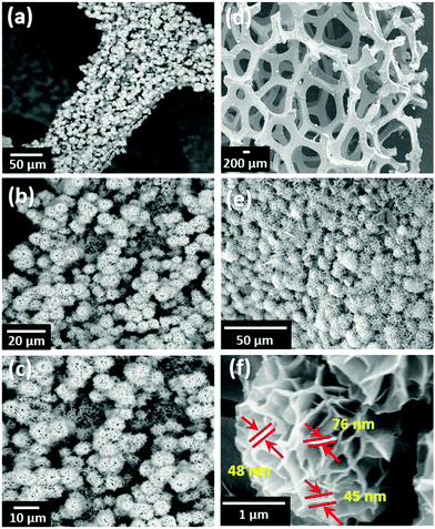 | ||
| Fig. 3 FESEM surface morphology of (a–c) MNS, (d–e) MNS-G-2.5 composite, and (f) Enlarged view of the MNS-G-2.5 composite 3D flower. | ||
The N2 adsorption and desorption studies were performed for the MNS-G-2.5 sample to obtain details about surface area and pore distribution. As shown in Fig. S6a (ESI†), the sample displays a surface area of 17.9 m2 g−1, which is high compared to the value reported earlier.52 This high specific surface area is a result of the 3D flower-like structure of the MNS-G-2.5 composite.53,54 The pore size distribution of the MNS-G-2.5 sample is shown in Fig. S6b (ESI†). The pore size distribution is hierarchical and shows an average pore size of 16.7 Å, which helps in facilitating the rigorous diffusion of electrolyte ions during the charging/discharging process.55
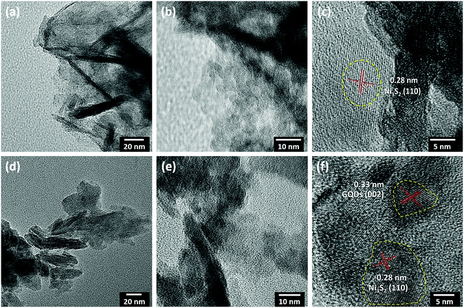
The shape and structure of MNS and the MNS-G-2.5 composite were further evaluated using TEM at higher magnifications. Fig. 4 shows the sheet-like morphology of MNS (Fig. 4a–c) and MNS-G-2.5 (Fig. 4d–f) samples at low and high magnifications, respectively. The HRTEM image in Fig. 4c reveals that the observed lattice interplanar spacing of around 0.28 nm corresponds to the (110) plane of the heazlewoodite phase of Ni3S2 which was also confirmed earlier through XRD analysis.56,57 The lattice fringes of the MNS-G-2.5 composite as shown in Fig. 4f exhibit interplanar spacing of 0.28 and 0.33 nm matching well with the (110) plane of Ni3S2 and the (002) plane of GQDs, respectively. Fig. S7 (ESI†) shows the indexed selected area electronic diffraction pattern of the MNS-G-2.5 composite, which affirms the two sets of diffraction patterns. The inner bright spots may be assigned to metallic Mo, and the spots with ring patterns can be indexed to the Ni3S2 phase. These results confirm the presence of metallic Mo element and the formation of the Mo/Ni3S2 composite.
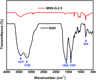
The Fourier transform infrared (FT-IR) spectra of GQDs and MNS-G-2.5 are shown in Fig. 5. The stretching vibrations at 3431 cm−1 and 3180 cm−1 correspond to N–H and O–H, and the vibrations at 1585 cm−1 and 1400 cm−1 are assigned to C–C and C–N functional groups, respectively, which further confirms the presence of nitrogen element.42,58 The MNS-G-2.5 composite retains all of the characteristic peaks from GQDs, indicating the successful incorporation of GQDs into the MNS-G-2.5 sample. During the hydrothermal synthesis, most of the functional groups of GQDs are reduced and this would have resulted in the decreased intensity of peaks in the MNS-G-2.5 sample. It is worth mentioning that the introduction of GQDs into the Ni3S2 matrix results in the creation of more dislocations and distortions, which resulted in the formation of more defects.42 These results indicated the formation of the MNS-G-2.5 composite, which are quite consistent with the XRD and TEM analyses.
Electrochemical performance
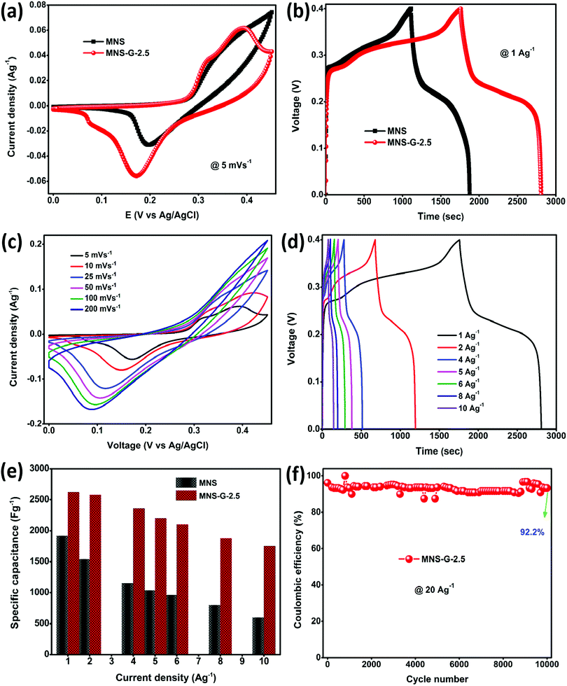
CV, GCD, and EIS were used to evaluate the electrochemical performance of the as-prepared MNS and MNS-G-2.5 composite. Fig. 6a shows the comparison of the cyclic voltammogram curves of MNS and the MNS-G-2.5 composite at 5 mV s−1. As clearly indicated by the larger area under the cyclic voltammogram curve for MNS-G-2.5 than that for the only MNS, one can easily conclude the improvement in electrochemical performance, which is further indicated later in terms of the higher capacitance of MNS-G-2.5. The separation voltage between the oxidation and reduction peaks for the MNS-G-2.5 composite is 0.17 V, whereas it is around 0.22 V for MNS. The lower peak separation in the GQD induced composite compared to the pristine MNS sample may be associated with the rate of the charge transfer process which further confirms the superior performance of the GQD doped composite. Fig. 6b shows the comparison of the GCD curves of the two composites at a current density of 1 A g−1. The inclusion of GQDs into the MNS composite induces more electrochemically active surface areas, which in turn results in the higher discharge time of the MNS-G-2.5 composite electrode. Furthermore, the cyclic voltammogram curves of the MNS-G-2.5 composite recorded in a 3 M KOH electrolyte in a potential window from 0 to 0.45 V are shown in Fig. 6c. All cyclic voltammogram curves comprising one oxidation and one reduction peak indicate the pseudocapacitive nature of the MNS-G-2.5 composite, which is guided by reversible faradaic Ni2+/Ni3+ redox reactions. Fig. S8 (ESI†) further confirms the role of GQDs in providing a larger electrochemically active surface area in terms of the increase in the redox current of the composite compared to the only MNS electrode. The detailed redox reaction that occurs in the alkaline electrolyte is as follows:| Ni3S2 + 3OH− ↔ Ni3S2(OH)3 + 3e− |
The regularity in the oxidation and reduction peaks in the cyclic voltammogram curves of the composite shows its good reversibility. With an increase in the scan rate, the cyclic voltammogram curves are shifting because at lower scan rates there is enough time for the electrolyte ions to sweep the inner surface of the electrode but at higher scan rates the ions can only reach the external surface of the electrode material, resulting in the reduction of the active sites.52,59 Cyclic voltammogram curves for different GQD loadings are shown in Fig. S9 (ESI†). The shift of oxidation and reduction peaks with an increase in the scan rate from 5 to 200 mV s−1 reflects a change in the internal resistance, improved mass transportation, and better electron conduction in the MNS-G-2.5 composite. GCD curves further confirm the enhanced electrochemical performance of MNS-G-2.5 and Ni3S2-GQD (Fig. S10a, ESI†) composite electrodes with different applied current densities from 1 to 10 A g−1 as shown in Fig. 6d. The specific capacitance of the MNS-G-2.5 composite can be calculated from the GCD curves using eqn (1). The charge–discharge curves of the electrode shows a pseudocapacitive nature, without any IR drop, good reversibility, and an outstanding coulombic efficiency. Fig. 6e shows the specific capacitance of the MNS, MNS-G-2.5 and Ni3S2-GQD (Fig. S10b, ESI†) electrodes at different current densities. The MNS-G-2.5 electrode showed an ultra-high specific capacitance of 2622 F g−1 when compared to the pristine MNS electrode, for which the value was 1915 F g−1 at a current density of 1 A g−1. Even at a high current density of 10 A g−1, the MNS-G-2.5 electrode delivered a specific capacitance of 1750 F g−1 with a capacitance retention of 66.7%, showing its extraordinary ability towards the development of a high-performance supercapacitor. The specific capacitance values are higher than most of the reported nickel sulfide-based materials (Table S1, ESI†). Whereas pristine MNS shows a poor capacitance retention of 31.3% (Fig. S11, ESI†), the incorporation of GQDs into the MNS matrix improved the specific capacitance of the composite and resulted in a better capacitance retention in order to achieve an ultra-high specific capacitance of the GQD doped composite. The GCD curves of MNS-G-n with various GQD loadings can be found in Fig. S12 (ESI†). As observed earlier also in the literature, simultaneous doping of molybdenum and GQDs into the Ni3S2 matrix not only improved the electrical conductivity of the electrode but also resulted in the creation of more electrochemically active surfaces and contributed to achieving an ultra-high specific capacitance. Xie et al. synthesized a Cobalt doped Ni3S2 binder-free electrode, which showed improved electrochemical properties compared to the pristine Ni3S2 electrode.52 Qi et al. prepared Ag-doped Ni3S2 sheets and concluded that Ag nanoparticles improved the electrical conductivity of the electrode.60 Similarly, the incorporation of carbon quantum dots into the NiS matrix performed by Sahoo et al. also resulted in an increase in the electrochemical performance of the electrode.39 To evaluate the electrochemical performance of the supercapacitor electrode, cyclic stability is one of the most crucial parameters. As shown in Fig. 6f, the cyclic stability of the MNS-G-2.5 electrode is exhibited by repetitive charge–discharge processes at a high current density of 20 A g−1 for 10![[thin space (1/6-em)]](https://www.rsc.org/images/entities/char_2009.gif) 000 cycles. Interestingly, the composite electrode shows a 92.2% coulombic efficiency by losing only 7.8% over 10
000 cycles. Interestingly, the composite electrode shows a 92.2% coulombic efficiency by losing only 7.8% over 10![[thin space (1/6-em)]](https://www.rsc.org/images/entities/char_2009.gif) 000 cycles, indicating its potential for designing high-performance supercapacitors. The superior performance of the MNS-G-2.5 electrode may be related to the availability of a sufficient number of electrolyte ions during rapid charge/discharge processes.50,61 Furthermore, Fig. S13 (ESI†) shows the preserved 3D flower morphology of the MoNiS-G-2.5 composite after the stability test of 10
000 cycles, indicating its potential for designing high-performance supercapacitors. The superior performance of the MNS-G-2.5 electrode may be related to the availability of a sufficient number of electrolyte ions during rapid charge/discharge processes.50,61 Furthermore, Fig. S13 (ESI†) shows the preserved 3D flower morphology of the MoNiS-G-2.5 composite after the stability test of 10![[thin space (1/6-em)]](https://www.rsc.org/images/entities/char_2009.gif) 000 cycles, as an evidence for achieving high cyclic stability and coulombic efficiency. Furthermore, XRD analysis was carried out to check whether oxidation has occurred or not. From Fig. S14 (ESI†) we can observe that all Ni3S2 peaks are present and no additional peaks are observed. This confirms that oxidation does not occur in the sample during electrochemical testing. To further investigate the intrinsic electrochemical performance of the prepared composite an EIS test was conducted. Fig. S15a (ESI†), shows the Nyquist plots of MNS and MNS-G-2.5 electrodes in the frequency range from 100 kHz to 0.01 Hz, and the fitted equivalent circuit is shown in (Fig. S15b, ESI†). The partial semi-circle region at a higher frequency corresponds to the charge transfer resistance (Rct), which forms at the electrode–electrolyte interface during the electrochemical process. The MNS-G-2.5 composite shows a lower Rct (1.3 Ω) value compared to the pristine MoNiS electrode (12 Ω). This can be attributed to the introduction of GQDs into the MoNiS matrix, which enhanced the conductivity of the composite as discussed above and resulted in lower Rct values. Huang et al. obtained a similar conclusion from GQD/CuCo2S4, which shows lower Rct values compared to pristine CuCo2S4. Due to the higher conductivity of GQDs, introducing them into the MNS matrix resulted in a lower resistance and an increase in the conductivity of the composite.37 The positive synergistic effect of doped Mo metal particles into sheets like Ni3S2 and Ni foam conductive substrates and the GQD inclusion resulted in an overall elevation of the electrochemical performance of the composite. This was possible due to (i) the binder free synthesis of the composite on Ni foam which resulted in a high conductivity substrate,62 (ii) the flower-like morphology of the composite which not only provided enormous electroactive sites for electrolyte ion adsorption but also facilitated the charge transportation process,63–65 (iii) the uniform decoration of molybdenum particles in the Ni3S2 matrix which enhanced the electrical conductivity of MNS-G-n composites,66–68 and (iv) the presence of highly conductive GQDs throughout the Ni3S2 matrix which elevated the electrical conductivity of the composite further and eased the charge–discharge process by minimizing the diffusion length.37,39 (v) Molybdenum leads to in situ cation substitution/doping into the nickel sulfide, which can induce a synergistic effect between Mo and Ni and change the electronic structure of the metal sites, leading to improved electrochemical performance.68,69
000 cycles, as an evidence for achieving high cyclic stability and coulombic efficiency. Furthermore, XRD analysis was carried out to check whether oxidation has occurred or not. From Fig. S14 (ESI†) we can observe that all Ni3S2 peaks are present and no additional peaks are observed. This confirms that oxidation does not occur in the sample during electrochemical testing. To further investigate the intrinsic electrochemical performance of the prepared composite an EIS test was conducted. Fig. S15a (ESI†), shows the Nyquist plots of MNS and MNS-G-2.5 electrodes in the frequency range from 100 kHz to 0.01 Hz, and the fitted equivalent circuit is shown in (Fig. S15b, ESI†). The partial semi-circle region at a higher frequency corresponds to the charge transfer resistance (Rct), which forms at the electrode–electrolyte interface during the electrochemical process. The MNS-G-2.5 composite shows a lower Rct (1.3 Ω) value compared to the pristine MoNiS electrode (12 Ω). This can be attributed to the introduction of GQDs into the MoNiS matrix, which enhanced the conductivity of the composite as discussed above and resulted in lower Rct values. Huang et al. obtained a similar conclusion from GQD/CuCo2S4, which shows lower Rct values compared to pristine CuCo2S4. Due to the higher conductivity of GQDs, introducing them into the MNS matrix resulted in a lower resistance and an increase in the conductivity of the composite.37 The positive synergistic effect of doped Mo metal particles into sheets like Ni3S2 and Ni foam conductive substrates and the GQD inclusion resulted in an overall elevation of the electrochemical performance of the composite. This was possible due to (i) the binder free synthesis of the composite on Ni foam which resulted in a high conductivity substrate,62 (ii) the flower-like morphology of the composite which not only provided enormous electroactive sites for electrolyte ion adsorption but also facilitated the charge transportation process,63–65 (iii) the uniform decoration of molybdenum particles in the Ni3S2 matrix which enhanced the electrical conductivity of MNS-G-n composites,66–68 and (iv) the presence of highly conductive GQDs throughout the Ni3S2 matrix which elevated the electrical conductivity of the composite further and eased the charge–discharge process by minimizing the diffusion length.37,39 (v) Molybdenum leads to in situ cation substitution/doping into the nickel sulfide, which can induce a synergistic effect between Mo and Ni and change the electronic structure of the metal sites, leading to improved electrochemical performance.68,69
Electrochemical performance of the MNS-G-2.5//rGO asymmetric supercapacitor device
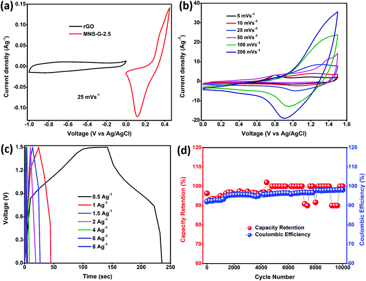
The potential application of Mo doped nickel sulfide for electrochemical energy storage was evaluated by fabricating an aqueous ASC device using MNS-G-2.5 as the positive electrode and rGO as the negative electrode in a 3 M KOH electrolyte. Fig. 7a shows the individual cyclic voltammogram curves of MNS-G-2.5 and rGO at a 25 mV s−1 scan rate measured in the three-electrode system. rGO exhibits a perfect rectangular shape in the 0 to 1.0 V range with no other redox peaks illustrating its double layer charge storage mechanism. From the cyclic voltammogram curves of both the electrodes, we can elucidate that the potential window of the MNS-G-2.5//rGO ASC device can reach up to 1.6 V in a 3 M KOH electrolyte. The cyclic voltammogram curves of the MNS-G-2.5//rGO ASC device are displayed in Fig. 7b. We can observe that the combination of double-layer capacitance and pseudo capacitance from the MNS-G-2.5 and rGO samples contributed to the total energy storage of the MNS-G-2.5//rGO ASC device. Moreover, there is no observable change in the cyclic voltammogram curves with an increase in the scan rate, which shows its excellent rate capability. As shown in Fig. 7c, the symmetric nature of the GCD curves with an increase in the current density demonstrates the MNS-G-2.5//rGO ASC device's reversibility of the electrochemical reaction and higher coulombic efficiency. The device exhibits specific capacitance values of 124 F g−1 and 56 F g−1 at 0.5 and 1 A g−1 current densities, respectively. The cyclic performance of the MNS-G-2.5//rGO ASC device was measured by repeating GCD for 10![[thin space (1/6-em)]](https://www.rsc.org/images/entities/char_2009.gif) 000 cycles at 2 A g−1 as indicated in Fig. 7d. The device delivers an extraordinary coulombic efficiency of 95.9% and impressive capacitance of 96.4% after 10
000 cycles at 2 A g−1 as indicated in Fig. 7d. The device delivers an extraordinary coulombic efficiency of 95.9% and impressive capacitance of 96.4% after 10![[thin space (1/6-em)]](https://www.rsc.org/images/entities/char_2009.gif) 000 cycles which reveals its superior electrochemical performance for long cyclic stability tests.
000 cycles which reveals its superior electrochemical performance for long cyclic stability tests.
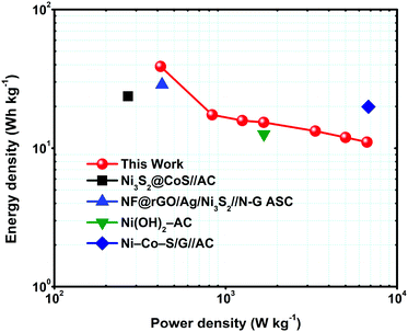
To determine the supercapacitor performance for real applications, energy and power density are two main parameters. Eqn (2) and (3) were used to calculate the energy and power density of the MNS-G-2.5//rGO ASC device and the corresponding Ragone plot is shown in Fig. 8. The device displays a higher energy density of 38.9 W h kg−1 at a power density of 416.6 W kg−1 and sustains at 11.06 W h kg−1 at a power density of 6666 W kg−1. The results mentioned above are much better than those reported in the literature for nickel sulfide materials.57,60,65,70
Conclusions
In summary, binder-free GQD- and molybdenum-incorporated nickel sulfide was prepared on Ni foam using facile one step hydrothermal synthesis and used as a high-performance supercapacitor electrode. The 3D flower-like morphology of the MNS-G-2.5 composite led to the production of more active edges on the nanostructures. A high specific capacitance (2622.5 F g−1 at 1 A g−1) was obtained for the optimized MNS-G-2.5 sample with an impressive cyclic stability of 98% after 10![[thin space (1/6-em)]](https://www.rsc.org/images/entities/char_2009.gif) 000 cycles. The prepared aqueous asymmetric supercapacitor device (MNS-G-2.5//rGO) shows an extraordinarily high energy density of 38.9 W h kg−1 at a power density of 416.6 W kg−1. In addition to that, the MNS-G-2.5//rGO device shows impressive cyclic stability and capacity retention of 95.9% and 96.4% after 10
000 cycles. The prepared aqueous asymmetric supercapacitor device (MNS-G-2.5//rGO) shows an extraordinarily high energy density of 38.9 W h kg−1 at a power density of 416.6 W kg−1. In addition to that, the MNS-G-2.5//rGO device shows impressive cyclic stability and capacity retention of 95.9% and 96.4% after 10![[thin space (1/6-em)]](https://www.rsc.org/images/entities/char_2009.gif) 000 cycles, respectively. Thus, we believe that these results open up new opportunities for metal-doped nickel sulfide materials for high performance supercapacitor applications.
000 cycles, respectively. Thus, we believe that these results open up new opportunities for metal-doped nickel sulfide materials for high performance supercapacitor applications.
Conflicts of interest
There are no conflicts to declare.Acknowledgements
The authors acknowledge the financial support received from the Ministry of Human Resources Development and Department of Heavy Industries, Govt. of India under the IMPRINT scheme (Project No. 7035) to carry out this work. The JEOL scanning electron microscope (JEOL JSM-7800F) used in this study was procured through the funding provided by the Department of Science and Technology under the DST-FIST program (Grant no. SR/FST/ETI-421/2016).Notes and references
- P. Simon, Y. Gogotsi and P. Simon, Nat. Mater., 2008, 7, 845–854 CrossRef CAS.
- G. Wang, L. Zhang and J. Zhang, Chem. Soc. Rev., 2012, 41, 797–828 RSC.
- G. Zhang and X. W. Lou, Adv. Mater., 2013, 25, 976–979 CrossRef CAS.
- H. Tang, J. Wang, H. Yin, H. Zhao, D. Wang and Z. Tang, Adv. Mater., 2015, 27, 1117–1123 CrossRef CAS.
- G. Gao, H. Bin Wu, S. Ding, L. M. Liu and X. W. Lou, Small, 2015, 11, 804–808 CrossRef CAS.
- H. Chen, L. Hu, M. Chen, Y. Yan and L. Wu, Adv. Funct. Mater., 2014, 24, 934–942 CrossRef CAS.
- G. A. Snook, P. Kao and A. S. Best, J. Power Sources, 2011, 196, 1–12 CrossRef CAS.
- W. Wei, L. Mi, Y. Gao, Z. Zheng, W. Chen and X. Guan, Chem. Mater., 2014, 26, 3418–3426 CrossRef CAS.
- X. Y. Yu, L. Yu, H. Bin Wu and X. W. Lou, Angew. Chem., Int. Ed., 2015, 54, 5331–5335 CrossRef CAS.
- Z. Zhang, Q. Wang, C. Zhao, S. Min and X. Qian, ACS Appl. Mater. Interfaces, 2015, 7, 4861–4868 CrossRef CAS.
- L. Ma, X. Shen, Z. Ji, S. Wang, H. Zhou and G. Zhu, Electrochim. Acta, 2014, 146, 525–532 CrossRef CAS.
- X. Liu, X. Qi, Z. Zhang, L. Ren, Y. Liu, L. Meng, K. Huang and J. Zhong, Ceram. Int., 2014, 40, 8189–8193 CrossRef CAS.
- J. Yang, X. Duan, Q. Qin and W. Zheng, J. Mater. Chem. A, 2013, 1, 7880–7884 RSC.
- K. Tao, Y. Gong, Q. Zhou and J. Lin, Electrochim. Acta, 2018, 286, 65–76 CrossRef CAS.
- V. H. Nguyen, C. Lamiel and J. J. Shim, Electrochim. Acta, 2015, 161, 351–357 CrossRef CAS.
- N. Parveen, S. A. Ansari, S. G. Ansari, H. Fouad, N. M. Abd El-Salam and M. H. Cho, Electrochim. Acta, 2018, 268, 82–93 CrossRef CAS.
- L. Yu, B. Yang, Q. Liu, J. Liu, X. Wang, D. Song, J. Wang and X. Jing, J. Electroanal. Chem., 2015, 739, 156–163 CrossRef CAS.
- W. Hu, R. Chen, W. Xie, L. Zou, N. Qin and D. Bao, ACS Appl. Mater. Interfaces, 2014, 6, 19318–19326 CrossRef CAS.
- J. Yan, H. Wu, P. Li, H. Chen, R. Jiang and S. Liu, J. Mater. Chem. A, 2017, 5, 10173–10181 RSC.
- F. Robert, Science, 2007, 315, 2007 Search PubMed.
- B. Cui, H. Lin, J. B. Li, X. Li, J. Yang and J. Tao, Adv. Funct. Mater., 2008, 18, 1440–1447 CrossRef CAS.
- L. Zhang and X. S. Zhao, Chem. Soc. Rev., 2009, 38, 2520–2531 RSC.
- E. Frackowiak, Phys. Chem. Chem. Phys., 2007, 9, 1774–1785 CAS.
- F. Cai, R. Sun, Y. Kang, H. Chen, M. Chen and Q. Li, RSC Adv., 2015, 5, 23073–23079 RSC.
- Y. Chang, Y. W. Sui, J. Q. Qi, L. Y. Jiang, Y. Z. He, F. X. Wei and Q. K. Meng, Mater. Lett., 2016, 176, 274–277 CrossRef CAS.
- D. Potphode and C. S. Sharma, J. Energy Storage, 2020, 27, 101114 CrossRef.
- J. He, C. Guo, S. Zhou, Y. Zhao, Q. Wang, S. Yang, J. Yang and Q. Wang, Inorg. Chem. Front., 2019, 6, 226–232 RSC.
- Y. Yan, J. Gong, J. Chen, Z. Zeng, W. Huang, K. Pu, J. Liu and P. Chen, Adv. Mater., 2019, 31, 1–22 Search PubMed.
- M. Li, T. Chen, J. J. Gooding and J. Liu, ACS Sens., 2019, 4, 1732–1748 CrossRef CAS.
- S. Tachi, H. Morita, M. Takahashi, Y. Okabayashi, T. Hosokai, T. Sugai and S. Kuwahara, Sci. Rep., 2019, 9, 1–7 CrossRef CAS.
- Y. Wang and A. Hu, J. Mater. Chem. C, 2014, 2, 6921–6939 CAS.
- S. Zhu, J. Zhang, C. Qiao, S. Tang, Y. Li, W. Yuan, B. Li, L. Tian, F. Liu, R. Hu, H. Gao, H. Wei, H. Zhang, H. Sun and B. Yang, Chem. Commun., 2011, 47, 6858–6860 CAS.
- J. Zhao, G. Chen, L. Zhu and G. Li, Electrochem. Commun., 2011, 13, 31–33 CrossRef CAS.
- S. Zhang, L. Sui, H. Dong, W. He, L. Dong and L. Yu, ACS Appl. Mater. Interfaces, 2018, 10, 12983–12991 CrossRef CAS.
- V. B. Kumar, A. Borenstein, B. Markovsky, D. Aurbach, A. Gedanken, M. Talianker and Z. Porat, J. Phys. Chem. C, 2016, 120, 13406–13413 CrossRef CAS.
- A. Prasath, M. Athika, E. Duraisamy, A. S. Sharma and P. Elumalai, ChemistrySelect, 2018, 3, 8713–8723 CrossRef CAS.
- Y. Huang, L. Lin, T. Shi, S. Cheng, Y. Zhong, C. Chen and Z. Tang, Appl. Surf. Sci., 2019, 463, 498–503 CrossRef CAS.
- M. Zhang, W. Liu, R. Liang, R. Tjandra and A. Yu, Sustainable Energy Fuels, 2019, 3, 2499–2508 RSC.
- S. Sahoo, A. K. Satpati, P. K. Sahoo and P. D. Naik, ACS Omega, 2018, 3, 17936–17946 CrossRef CAS.
- T. W. Lin, C. J. Liu and C. S. Dai, Appl. Catal., B, 2014, 154–155, 213–220 CrossRef CAS.
- Y. Chang, Y. Sui, J. Qi, L. Jiang, Y. He, F. Wei, Q. Meng and Y. Jin, Electrochim. Acta, 2017, 226, 69–78 CrossRef CAS.
- J. Li, X. Zhang, Z. Zhang, Z. Li, M. Gao, H. Wei and H. Chu, Electrochim. Acta, 2019, 304, 487–494 CrossRef CAS.
- C. Zhang, Y. Huang, S. Tang, M. Deng and Y. Du, ACS Energy Lett., 2017, 2, 759–768 CrossRef CAS.
- Z. Cheng, H. Abernathy and M. Liu, J. Phys. Chem. C, 2007, 111, 17997–18000 CrossRef CAS.
- I. D. Dobrea, C. E. Ciocan, E. Dumitriu, M. I. Popa, E. Petit and V. Hulea, Appl. Clay Sci., 2015, 104, 205–210 CrossRef CAS.
- A. C. Ferrari and D. M. Basko, Nat. Nanotechnol., 2013, 8, 235–246 CrossRef CAS.
- E. Dervishi, Z. Ji, H. Htoon, M. Sykora and S. K. Doorn, Nanoscale, 2019, 11, 16571–16581 RSC.
- S. Raj, P. Kar and P. Roy, Chem. Commun., 2018, 54, 12400–12403 RSC.
- A. H. Chowdhury, I. H. Chowdhury and S. M. Islam, Ind. Eng. Chem. Res., 2019, 58, 11779–11786 CrossRef CAS.
- O. Sangabathula, D. Potphode and C. S. Sharma, ChemistrySelect, 2020, 5, 6809–6817 CrossRef.
- L. Zhou, J. Zhang, Y. Wu, W. Wang, H. Ming, Q. Sun, L. Wang, J. Ming and H. N. Alshareef, Adv. Energy Mater., 2019, 9(43), 1902194 CrossRef CAS.
- S. Xie, J. Gou, B. Liu and C. Liu, Inorg. Chem. Front., 2018, 5, 1218–1225 RSC.
- P. Xu, J. Liu, P. Yan, C. Miao, K. Ye, K. Cheng, J. Yin, D. Cao, K. Li and G. Wang, J. Mater. Chem. A, 2016, 4, 4920–4928 RSC.
- C. Wu, J. Maier and Y. Yu, Adv. Mater., 2016, 28, 174–180 CrossRef CAS.
- W. Zhou, X. Cao, Z. Zeng, W. Shi, Y. Zhu, Q. Yan, H. Liu, J. Wang and H. Zhang, Energy Environ. Sci., 2013, 6, 2216–2221 RSC.
- S. Yu, Y. Zhang, G. Lou, Y. Wu, X. Zhu, H. Chen, Z. Shen, S. Fu, B. Bao and L. Wu, Sci. Rep., 2018, 8, 1–12. CrossRef.
- R. Li, S. Wang, J. Wang and Z. Huang, Phys. Chem. Chem. Phys., 2015, 17, 16434–16442 RSC.
- W. Li, Y. Liu, M. Wu, X. Feng, S. A. T. Redfern, Y. Shang, X. Yong, T. Feng, K. Wu, Z. Liu, B. Li, Z. Chen, J. S. Tse, S. Lu and B. Yang, Adv. Mater., 2018, 30, 1–8 Search PubMed.
- R. N. Bulakhe, V. H. Nguyen and J. J. Shim, New J. Chem., 2017, 41, 1473–1482 RSC.
- J. Qi, Y. Chang, Y. Sui, Y. He, Q. Meng, F. Wei, Y. Ren and Y. Jin, Adv. Mater. Interfaces, 2018, 5, 1–9 Search PubMed.
- L. Liu, Z. Niu and J. Chen, Chem. Soc. Rev., 2016, 45, 4340–4363 RSC.
- X. Li, Q. Li, Y. Wu, M. Rui and H. Zeng, ACS Appl. Mater. Interfaces, 2015, 7, 19316–19323 CrossRef CAS.
- C. Z. Kang, F. S. Omar, S. Gunalan, K. Ramesh and S. Ramesh, Ionics., 2020, 26, 3621–3630 CrossRef CAS.
- J. Pu, F. Cui, S. Chu, T. Wang, E. Sheng and Z. Wang, ACS Sustainable Chem. Eng., 2014, 2, 809–815 CrossRef CAS.
- H. B. Li, M. H. Yu, F. X. Wang, P. Liu, Y. Liang, J. Xiao, C. X. Wang, Y. X. Tong and G. W. Yang, Nat. Commun., 2013, 4, 1–7 CAS.
- Y. Li and C. Zhao, Chem. Mater., 2016, 28, 5659–5666 CrossRef CAS.
- S. Peng, L. Li, H. Tan, R. Cai, W. Shi, C. Li, S. G. Mhaisalkar, M. Srinivasan, S. Ramakrishna and Q. Yan, Adv. Funct. Mater., 2014, 24, 2155–2162 CrossRef CAS.
- Y. Gao, L. Mi, W. Wei, S. Cui, Z. Zheng, H. Hou and W. Chen, ACS Appl. Mater. Interfaces, 2015, 7, 4311–4319 CrossRef CAS.
- T. Saravanakumar, T. Selvaraju, K. B. Bhojanaa, M. Ramesh, A. Pandikumar, R. Akilan, R. Shankar and S. J. Sardhar Basha, Dalton Trans., 2020, 49, 5336–5351 RSC.
- J. Yang, C. Yu, X. Fan, S. Liang, S. Li, H. Huang, Z. Ling, C. Hao and J. Qiu, Energy Environ. Sci., 2016, 9, 1299–1307 RSC.
Footnote |
| † Electronic supplementary information (ESI) available: XRD patterns of MNS-G-n composites, RAMAN spectrum and FESEM images of GQDs, elemental mapping, EDS, N2 adsorption isotherms and SAED patterns of MNS-G-2.5 composite, cyclic voltammograms and GCD curves of MNS-G-n and NS-G-n composites, FESEM and XRD of MNS-G-n composites after cyclic stability, EIS plots of MNS, MNS-G-2.5 composite, electrochemical performance comparison of the reported nickel sulfide based materials. See DOI: 10.1039/d0ma00593b |
| This journal is © The Royal Society of Chemistry 2020 |

