
 Open Access Article
 This Open Access Article is licensed under a
 Creative Commons Attribution 3.0 Unported Licence
Metal–organic frameworks as promising electrocatalysts for the nitrogen reduction reaction: mapping the research landscape and identifying future trends
Riki
Nakatani
 a,
Saikat
Das
*a and
Yuichi
Negishi
*ab
a,
Saikat
Das
*a and
Yuichi
Negishi
*ab
aDepartment of Applied Chemistry, Faculty of Science, Tokyo University of Science, 1-3 Kagurazaka, Shinjuku-ku, Tokyo 162-8601, Japan. E-mail: saikatdas@rs.tus.ac.jp
bInstitute of Multidisciplinary Research for Advanced Materials, Tohoku University, 2-1-1 Katahira, Aoba-ku, Sendai 980-8577, Japan. E-mail: yuichi.negishi.a8@tohoku.ac.jp
First published on 6th September 2024
Abstract
Since the pioneering discovery of metal–organic frameworks (MOFs) a quarter century ago, they have evolved as a new category of porous crystalline extended network structures with atomic/molecular level designability. The distinctive porosity and structural customizability of MOFs have been crucial to their wide spectrum of applications. Among these applications, MOFs have gained prominence as electrocatalysts in the nitrogen reduction reaction (NRR), which has inimitable potential to solve environmental crises. The reticular structures of MOFs with uniformly distributed active sites and their easy accessibility endow them with enhanced catalytic activity. In this review, we provide a comprehensive overview of MOF catalyst design protocols from molecular building blocks to extended networks, and discuss how precisely designed MOF electrocatalyst structures can explicitly control targeted NRR pathways, besides giving an insight into the future prospects and challenges.
 Riki Nakatani | Riki Nakatani is a first year Master's course student in Prof. Negishi's group at Tokyo University of Science (TUS). His research interests include the synthesis of metal–organic frameworks (MOFs) for energy and environmental applications. |
 Saikat Das | Saikat Das is a Junior Associate Professor in Prof. Negishi's group at TUS. He received his PhD degree in Chemistry and Physics of Polymers (2018) from Jilin University, China, under the supervision of Prof. Teng Ben. His research interests encompass the designed construction of novel MOFs and covalent organic frameworks (COFs). |
 Yuichi Negishi | Yuichi Negishi is currently a Professor at the Institute of Multidisciplinary Research for Advanced Materials at Tohoku University. He received his PhD degree in Chemistry (2001) from Keio University under the supervision of Prof. Atsushi Nakajima. He was employed as an Assistant Professor at Keio University and the Institute for Molecular Science. Prior to joining Tohoku University, he was a Professor at TUS. His research interests include the structural and functional exploration of atomically precise metal nanoclusters, MOFs and COFs. |
1. Introduction
Since the seminal discovery of metal–organic frameworks (MOFs) as cutting-edge porous inorganic–organic hybrid materials following zeolites, they have come a long way in terms of fundamental studies and practical applications.1,2 MOFs are assembled materials that consist of metal ions or nanoclusters as nodes (nodes are also regarded as secondary building units, SBUs) and electron-donating organic molecules as multidentate linkers that are linked through coordination bonds.3–6 The combination of a wide range of metals and linkers results in a variety of physicochemical properties: pore metrics and environment, internal surface area, optoelectronic characteristics and so forth. Furthermore, the structures have superb stability and crystallinity coupled with high porosity. Therefore, a plethora of applications (gas separation, drug delivery, water harvesting, biomedicine, sensing, magnetism, proton conduction, etc.) have been explored to leverage the intrinsic advantages of MOFs.7–13 MOFs have captivated the scientific community and hitherto approximately 100![[thin space (1/6-em)]](https://www.rsc.org/images/entities/char_2009.gif) 000 MOFs have been reported.14 As of now, the momentum for research in this field remains strong.
000 MOFs have been reported.14 As of now, the momentum for research in this field remains strong.
Studies in recent years have documented a diverse range of materials harnessed for heterogeneous catalysis research that include supported metal nanoparticles,15 nanoclusters,16 single atoms,17 metal oxides,18 zeolites,19 mesoporous silica,20 MOFs,21 and covalent organic frameworks (COFs),22 among others. Progress notwithstanding, significant gaps still exist, which necessitates addressing several limitations and challenges: (i) the activity, selectivity and durability of functional heterogeneous catalysts for targeted reactions fall well short due to structural degradation and challenges of achieving precise conditions and intricate techniques for the controlled synthesis of catalysts; (ii) the structural and chemical complexity of heterogeneous catalyst systems leads to a poor comprehension of the mechanisms of surface-catalysed reactions and structure–activity correlations, which hinders systematic design approaches to optimal catalysts.23 Regarding the development and optimization of heterogeneous catalysts, we should maintain a proper balance between material-specific properties and properties that are defined by the relationship of the catalyst with its environment. Accordingly, the materials suitable as heterogeneous catalysts must be endowed with the following characteristics: first, the design and synthesis of materials should be in favor of achieving a uniform and dispersed active site distribution; the former ensures high selectivity toward the products of interest while the latter results in high activity. Second, the structure of catalytic materials needs to be sufficiently robust so as to achieve high activity while allowing long-term stability and recyclability over consecutive runs. Third, the tailorability of the material components could provide precise control over catalytic activity and selectivity at the atomic level.
Ammonia (NH3) is necessary to produce nitrogen-based fertilizers and is extensively used as a carbon-free energy source, serving as an alternative to fossil fuels.24 On the other hand, nitrogen occupying the majority of the atmosphere possesses high stability and chemical inactivity because of its triple bond. In early 20th century, Fitz Haber and Carl Bosch developed the breakthrough process, known as Haber–Bosch process, which produced NH3 from N2 and H2 with a single pass conversion of usually 10–15%.25,26 However, the reaction is energy-intensive and entails catalysts operating at elevated temperatures of 400–550 °C and pressures of 15–25 MPa.27 As a result, 2% of energy consumption and 0.5% of green-house gas emission in the world are attributed to this process.28 Therefore, the eco-friendly nitrogen reduction reaction (NRR) utilizing low energy is highly coveted. The electrocatalytic NRR is attracting the attention of the scientific community as a clean and green sustainable approach.29 The electrochemical NRR (eNRR) is capable of producing NH3 from N2 gas and H2O as a hydrogen source at ambient temperature and pressure, consuming much lower energy than conventional processes.30 Herein, we show the reactions occurring at each electrode as follows:31
Anode reaction (in acid electrolyte):
| 3H2O → 3/2O2 + 6H+ + 6e− |
Anode reaction (in base electrolyte):
| 6OH− → 3H2O + 3/2O2 + 6e− |
Cathode reaction (in acid electrolyte):
| N2 + 6H+ + 6e− → 2NH3 |
Cathode reaction (in base electrolyte):
| N2 + 6H2O + 6e− → 2NH3 + 6OH− |
Overall reaction:
| N2 + 3H2O → 2NH3 + 3/2O2 |
As the eNRR is an emerging field with increasing research interest, numerous materials have been tested as catalysts for the eNRR. Transition metals such as Ru, Mo, Rh and Fe have been actively studied for improving NRR activity by facilitating the cleavage of N![[triple bond, length as m-dash]](https://www.rsc.org/images/entities/char_e002.gif) N bonds.32 Transition metal oxides are enticing catalysts for enhancing NRR activity by forming oxygen vacancies and doping heteroatoms or metals, which function as reaction sites.33 However, transition metal oxides face challenges such as low electrical conductivity, poor stability under acidic conditions, and weak adsorption strength, which limit their activity in the NRR.34 Single-atom catalysts (SACs) minimize the amount of metal and allow each individual metal atom to drive the reaction. Nevertheless, they are known to face stability issues, as single atoms tend to aggregate during the eNRR. To overcome this issue, aggregation while maintaining sufficient active sites should be prevented, although this approach is still under investigation.35 In addition to the aforementioned metal catalysts, environment-friendly catalysts that do not use metals, such as graphene, g-C3N4, COFs, etc. have also been developed.36 These non-metal electrocatalysts are suitable for the NRR because their low proton adsorption ability suppresses the HER. However, they exhibit a low nitrogen conversion rate and low current density in NH3 production, resulting in lower NH3 generation efficiency compared to metal catalysts, which makes their practical application difficult. As hybrid materials composed of metal atoms and organic ligands, MOFs provide some remarkable merits as catalysts for the eNRR: (i) MOFs enable atomically precise structural design; (ii) MOFs have the potential to function as molecular sieves, which increases the concentration of specific molecules; and (iii) the ordered lattice structure provides well-defined active sites, which simplifies the consideration of reaction mechanisms.
N bonds.32 Transition metal oxides are enticing catalysts for enhancing NRR activity by forming oxygen vacancies and doping heteroatoms or metals, which function as reaction sites.33 However, transition metal oxides face challenges such as low electrical conductivity, poor stability under acidic conditions, and weak adsorption strength, which limit their activity in the NRR.34 Single-atom catalysts (SACs) minimize the amount of metal and allow each individual metal atom to drive the reaction. Nevertheless, they are known to face stability issues, as single atoms tend to aggregate during the eNRR. To overcome this issue, aggregation while maintaining sufficient active sites should be prevented, although this approach is still under investigation.35 In addition to the aforementioned metal catalysts, environment-friendly catalysts that do not use metals, such as graphene, g-C3N4, COFs, etc. have also been developed.36 These non-metal electrocatalysts are suitable for the NRR because their low proton adsorption ability suppresses the HER. However, they exhibit a low nitrogen conversion rate and low current density in NH3 production, resulting in lower NH3 generation efficiency compared to metal catalysts, which makes their practical application difficult. As hybrid materials composed of metal atoms and organic ligands, MOFs provide some remarkable merits as catalysts for the eNRR: (i) MOFs enable atomically precise structural design; (ii) MOFs have the potential to function as molecular sieves, which increases the concentration of specific molecules; and (iii) the ordered lattice structure provides well-defined active sites, which simplifies the consideration of reaction mechanisms.
Regarding the catalysts used for the eNRR, their stability and conductivity are not yet up to the mark and pose challenges.37 Commonly, most MOFs behave as insulators (conductivity <10−10 S cm−1) owing to the absence of energy pathway for charge transport or free charge carriers.38 However, recently some methods have successfully provided MOFs with sufficient conductivity, enabling their utilization in electrochemical applications: implementing specific linkers, introducing guest molecules, and loading with conducting hosts, among others.39 Additionally, the kind of metals used to construct MOFs is also one of the important factors to consider in catalysis, which decides the cost and versatility. Since the first research on MOFs exploited as eNRR catalysts, subsequent studies have enriched this field substantially. Notably, some previous reviews have already provided an overview of MOFs as catalysts for the NRR.40–45 However, there is still a need for in-depth investigation of the correlation between catalytic activities and atomic-level structures of MOFs, as well as recent experimental and theoretical developments in this field. This review provides a unique perspective on understanding the NRR mechanisms and strategies by exploring the interplay of metal sites, functional modules, catalytic species, defects and the confined microenvironment in the MOF crystalline structure. In this review, we illustrate the core concepts of the NRR, avant-garde MOFs harnessed for the NRR, design processes and recent developments in MOF electrocatalysts, as well as chronologically trace the journey of NRR electrocatalysts with MOFs. In terms of unique traits of MOFs, they have ordered uniformity and porosity that enable guest molecules to access active sites readily. Furthermore, we discuss future directions to advance this field in the last section of this review.
2. The history of pristine MOFs as electrocatalysts
MOFs are highly designable porous materials that can be constructed by changing the combinations of diverse linkers and metal nodes. Hence, MOFs enable precise designability well-suited for specific applications by adjusting the precursors.46 In this section, we will introduce the evolution of MOFs utilized as electrocatalysts by presenting notable research across various electrochemical reactions.2.1. MOFs as electrocatalysts for the HER
The electrocatalytic hydrogen evolution reaction (HER) from water is considered as a promising route for producing hydrogen, which can be utilized as a sustainable energy carrier thereby addressing energy and environmental concerns. In 2011, non-noble metal polyoxometalate-based MOF ε(trim)4/3, (TBA)3·[PMoV8MoVI4O36 (OH)4Zn4][C6H3(COO)3]4/3·6H2O, was employed as the HER catalyst by Dolbecq and co-workers.47 To perform this reaction, a carbon paste modified electrode for introducing POMOF (POMOF/CPE) was applied. The cyclic voltammetry (CV) results displayed a peak that was associated with the HER process. The HER turnover frequency of ε(trim)4/3/CPE was ca. 6.7 s−1 with a 200 mV overpotential in water. Encouraged by the potential of cobalt dithiolene as a catalyst for the HER from water,48 the Marinescu group integrated it into two-dimensional (2D) Co MOFs (MOS1 and MOS2) to study its competency for the same application.49 The faradaic yield of H2 was 97 ± 3% with MOS1 on a glassy carbon (GC) electrode at pH = 2.6 and −0.8 V vs. the standard hydrogen electrode (SHE). A research study by the Li group in 2021 showed that NiRux-BDC served as the electrocatalyst for the HER.50 As revealed by linear sweep voltammetry (LSV) measurements, NiRu0.13-BDC exhibited the highest HER activity (the overpotential to reach 10 mA cm−2 was 36 mV) among various NiRux-BDC MOFs with different molar ratios of Ru/Ni and Ni-BDC in phosphate buffered saline solution. The Tafel slopes also indicated that NiRu0.13-BDC possessed the most promising potential to implement it for the HER. Furthermore, the electrocatalytic activity of NiRu0.13-BDC was also confirmed in acidic and basic solutions (1 M HCl and KOH aqueous), where it still showcased good HER activities.2.2. MOFs as electrocatalysts for the OER
Constructing highly efficient and selective electrocatalysts is critical to convert water into value-added chemicals like oxygen via the oxygen evolution reaction (OER) in order to achieve sustainability in efficient energy utilization. By virtue of their distinct structural features, MOFs have gained recognition as OER electrocatalysts, displaying noteworthy activity, selectivity and stability. In 2010, a study by Marken and colleagues showed that the Fe(BTC) MOF was used as an electrocatalyst for the OER.51 This reaction was conducted in NaOH containing 0.1 M KCl solution as the electrolyte. The peak current was found to be in direct proportion with hydroxide concentration. The number of electrons releasing from each hydroxide was calculated to be 0.63, which plausibly explains the generation of oxygen. In 2016, Liu, Zhao, and Tang et al. investigated the electrocatalytic OER activity of NiCo-UMOFNs.52 The onset potential and overpotential of NiCo-UMOFNs on GC were 1.42 V vs. RHE and 1.479 V vs. RHE at 10 mA cm−2, respectively, and both values were lower than those of Ni-UMOFNs, Co-UMOFNs and bulk NiCo-MOFs. Moreover, changing CP to conductive copper foam enhanced OER activity, which was revealed by the shifts of onset potential and overpotential. The FE of NiCo-UMOFNs reached 99.3% and no appreciable changes in anodic current could be observed for 200 hours at an overpotential of 0.25 V, demonstrating greater stability than RuO2. In 2019, Liu, Li and co-workers prepared CoBDC and then introduced Fc as a missing linker instead of BDC, thereby resulting in CoBDC-Fcx, where x represents the molar ratio of Fc/Fc + BDC.53 These MOFs were deposited on nickel foam (NF) and utilized as self-supported electrodes (CoBDC-NF and CoBDC-Fcx-NF). The overpotential to reach 10 mA cm−2 and Tafel slope for CoBDC-NF were 252 mV and 63 mV dec−1, respectively, and the corresponding values for CoBDC-Fcx-NF were 178 mV and 51 mV dec−1, respectively. Additionally, the stability of CoBDC-Fcx-NF was assessed by chronopotentiometry test and CV, which disclosed greater stability of CoBDC-Fcx-NF.2.3. MOFs as electrocatalysts for the ORR
The oxygen reduction reaction (ORR) is an electrochemical reaction of pivotal importance in energy conversion and storage systems like fuel cells. In 2012, Mao et al., for the first time, used MOFs as ORR electrocatalysts.54 Two novel copper-based MOFs, Cu-BTC and Cu-bipy-BTC were employed. GC electrodes were coated with MOFs (hereinafter Cu-BTC-modified GC and Cu-bipy-modified GC) and the electrocatalysis performance was confirmed by CV. Cu-BTC-modified GC showed superior performance in the ORR to only GC. However, the Cu-BTC-modified GC electrode was unstable under aqueous conditions. On the other hand, Cu-bipy-BTC-modified GC showed enough stability under the same conditions. Moreover, Cu-bipy-BTC-modified GC showed commendable electrocatalytic activity toward nearly 4e-reduction of O2, as evidenced by CV measurements. In 2016, a conductive 2D MOF, Ni3(HITP)2, was employed by Dincă and co-workers as an electrocatalyst for the ORR.55 The ORR onset potential was 0.82 V vs. RHE in 0.1 M KOH with a current density of −50 μA cm−2, which implied the highest ORR activities among non-platinum group metal catalysts. The stability of Ni3(HITP)2 was demonstrated through steady-state potentiostatic measurements with a potential of 0.77 V and the results revealed that the current density remained practically the same for more than 8 hours with a marginal decrease. A study by Cao and colleagues made use of zeolitic imidazolate frameworks (ZIFs) as the support for integrating Co porphyrins on the surface by ligand exchange upon the synthesis of ZIFs.56 The ORR Tafel plot of Co tetra(imidazolyl) porphyrin onto ZIF-8 (1@ZIF-8) showcased a slope of 53 mV dec−1, which was more gradual than the values of the compound precursors (1:62 mV dec−1, ZIF-8: 82 mV dec−1) and Pt/C (66 mV dec−1). The product selectivity of 1@ZIF-8 was confirmed by calculating the number (n) of electrons transferred per O2 and the value was 2.65, which implied lower selectivity than 1 (2.82), ZIF-8 (2.73) and Pt/C (3.92). Furthermore, to increase the selectivity of H2O production, ZIF-67 was introduced (1@ZIF-67) and this compound enabled to ameliorate the selectivity (n = 3.70). Another Co porphyrin ligand, Co tetra(4-imidazolylphenyl) porphyrin (hereinafter 2), was utilized instead of 1, and the n value of 2@ZIF-8 was 2.70 while that of 2@ZIF-67 was 3.70, which suggested the importance of distances between the Co ion into the porphyrin macrocycle and the MOF surface for better selectivity.
2.4. MOFs as electrocatalysts for the CRR
The overuse of fossil fuels has resulted in a drastic increase in CO2 concentration in air and is one of the root causes of global warming. Over the past few years, many research endeavors have engaged in utilizing CO2 to tackle the environmental concerns and energy scarcity. In 2012, Hinogami et al. implemented a new protocol to adopt MOFs as electrocatalysts for the CO2 reduction reaction (CRR).57 The MOF was constructed using Cu ions and rubeanic acid (denoted as CR-MOF), and the MOF slurry was dropped on conductive carbon paper (CP). CR-MOF electrodes generated HCOOH with an efficiency of 30% at −1.2 V, −1.4 V and −1.6 V vs. SHE, and the selectivity of HCOOH exceeded 98%. Additionally, the performance of CR-MOF and Cu metal electrodes was compared based on the amount of HCOOH produced (13.4 μmol cm−2 h−1 and 1.1 μmol cm−2 h−1, respectively) under the same conditions at −1.2 V vs. SHE. In 2016, Zhu, Han and colleagues implemented the Zn-BTC MOF for the electrocatalytic CRR in imidazolium based ionic liquid (IL) electrolytes for the first time.58 Zn-BTC was deposited on CP by the electrophoretic deposition technique and the resulting composite was named Zn-MOF/CP. The products obtained after the CRR by utilizing Zn-MOF/CP and IL BmimBF4 were mainly CH4 with small amounts of CO and H2 after a 2 hour reaction at −2.2 V vs. Ag/AgCl. Furthermore, the electrocatalytic study was scrutinized by comparing with other several ILs: BmimOTf, BmimPF6 and BmimClO4. The results suggested that existing F in ILs played an important role in achieving higher total current density (jtot) on account of interaction with CO2. Compared to other metal cathodes under the same conditions, both jtot and selectivity of CH4 of Zn-MOF/CP were remarkably better. In 2018, a research study by Lan and co-workers reported a CP based gas diffusion electrode (GDE) with Cu3(BTC)2 for CO2 capture (hereinafter GDE-CuMOF-x, x represents the mass ratio of Cu-MOF, x = 5, 7.5, 10, 15, and 20).59 The reduction currents of the GDE and GDE-CuMOF-x were measured, and each of the GDEs modified with CuMOF displayed lower values than the pristine GDE, which suggested the suppression of the HER as evident from the linear sweep voltammogram. The FEs for CH4 of GDE-CuMOF-5, 7.5, 10, and 15 were more than twice higher than that of the GDE at high overpotentials. Additionally, the best FEs for C2H4 were achieved when GDE-CuMOF-10 was leveraged. Moreover, the FE for H2 evolution was lowest for GDE-CuMOF-10. Regarding stability, GDE-CuMOF-10 exhibited higher stability at −2.5 V vs. the saturated calomel electrode for 6 hours relative to the GDE.2.5. MOFs as electrocatalysts for the EER
In 2010, Kitagawa and colleagues pioneered the use of [(HOC2H4)2dtoaCu] as a nonnoble-MOF catalyst for the ethanol electrooxidation reaction (EER).60 The conductivity of this MOF reached 3.3 × 10⁻⁴ S cm−1. This MOF also showed stability against sulfuric acid (1 M, 80 °C) and elevated temperatures (∼165 °C), making it suitable for use as an electrocatalyst. In this work, acetaldehyde, oxidation product of ethanol, was produced with the highest conversion ratio of 6.8% within 20 minutes (ethanol concentration was 0.5 M and the electrolyte volume was 20 mL).3. Background and state of the art of the NRR
3.1. The pathway of the NRR
The mechanism of the NRR encompasses various pathways occurring on the surface of heterogeneous catalysts. In this section, we will explain the NRR mechanisms that have been reported in previous research studies.In the dissociative pathway, the NN bond in the N2 molecule is first broken and each separated N atom is adsorbed on the surface of the catalyst. Following this, the hydrogenation of N atoms occurs and NH3 molecules are generated and released (Fig. 1a). In this process, the first reaction needs high energy because of the strong NN bond. In practice, the Haber–Bosch process typically follows this pathway.61
 | ||
| Fig. 1 Different pathways of the NRR: (a) dissociative pathway, (b) associative alternating pathway, (c) associative distal pathway, (d) enzymatic pathway, and (e) MvK pathway. | ||
In the associative alternating pathway, the N2 molecule is initially chemisorbed on the active sites in an end-on configuration. Secondly, hydrogenation takes place and one bond of NN is severed. After that, another hydrogenation reaction occurs and the second bond of N![[double bond, length as m-dash]](https://www.rsc.org/images/entities/char_e001.gif) N is severed. Finally, hydrogenation happens and two NH3 molecules are produced in sequence (Fig. 1b).
N is severed. Finally, hydrogenation happens and two NH3 molecules are produced in sequence (Fig. 1b).
The associative distal pathway also follows the same procedure as the associative alternating pathway until the halfway point. After being connected with the surface of the catalyst, the preferential hydrogenation of the nitrogen atom that is not adsorbed on the surface and the amputation of the NN bond gradually occur, and NH3 molecules are generated. After this, the nitrogen atom that is adsorbed on the surface also undergoes hydrogenation and a NH3 molecule is formed (Fig. 1c).
In the enzymatic pathway, first, a N2 molecule is attached in a side-on configuration on the catalyst surface. After this, hydrogenation of both N atoms occurs and one bond of NN is cleaved. Furthermore, the same process occurs again. Subsequently, a NH3 molecule is generated and released. Finally, the remaining N atom is converted to NH3 through hydrogenation and released (Fig. 1d).
The MvK pathway unfolds on the surface of TMN catalysts.62 Initially, the N atom which exists on the surface connects H atoms. After reduction of the N atom, the N atom is released as NH3. Following this, vacancies are created on the surface and the incoming N2 molecule is stuffed into the vacancy. Subsequently, the N atom which is not stuffed undergoes hydrogenation and is released as NH3. Finally, the remaining N atom regenerates the surface of the catalyst (Fig. 1e).
3.2. Methods for detecting NH3 and N2H4
One of the crucial factors in evaluating the performance of the NRR is the quantitative evaluation of the generated amount of NH3 as well as other potential by-products. This evaluation serves as a pivotal metric for comparing different catalysts in terms of efficacy. In this section, we discuss the detection techniques for the product NH3 and by-product hydrazine (N2H4), which were utilized in NRR research with MOFs. | ||
| Fig. 2 The overall indophenol method reaction between HClO, phenol and NH3 presented by Bolleter and colleagues. Adapted with permission from ref. 63. Copyright 1961, American Chemical Society. | ||
4. MOFs as electrocatalysts for the NRR
In this section, we will elucidate recent research reports on the utilization of MOFs as electrocatalysts for the NRR.4.1. Single metal MOFs for the NRR
In 2017, Yin and co-workers utilized three MOFs (denoted as MOF (Fe), MOF (Co) and MOF (Cu)) as electrocatalysts for the NRR at low temperature and ambient pressure.74 H2O and N2 (or air) were used as the precursors for this NRR. Under −1.2 V vs. Ag/AgCl and 90 °C conditions with water and N2 gas, the highest rates of NH3 generation in the case of MOF (Fe), MOF (Co) and MOF (Cu) were 2.12 × 10⁻⁹ mol s−1 cm−2, 1.64 × 10⁻⁹ mol s−1 cm−2 and 1.24 × 10⁻⁹ mol s−1 cm−2, respectively. Moreover, they utilized water and air instead of N2 as the raw materials and MOF (Fe) as the reaction catalyst under the same conditions. The results implied that the highest NH3 production rate was 1.52 × 10⁻⁹ mol s−1 cm−2. The highest current efficiencies for MOF (Fe), MOF (Co) and MOF (Cu) utilizing water and N2, and for MOF (Fe) using water and air were 1.43, 1.06, 0.96 and 0.88%, respectively, at 1.2 V vs. Ag/AgCl and 90 °C.In 2019, Wei and co-workers employed a self-supported catalyst CuII-MOF, [Cu24L12(H2O)12]·30DMF·14H2O, on carbon cloth (represented as JUC-1000/CC) as the cathode and anode for both the NRR and oxidation of SG to GA.75 First, JUC-1000/CC was utilized as the working electrode in the N2-saturated 1.0 M Na2SO4 solution electrolyte. As a result, the NH3 generation rate and FE were as high as 13.274 μg h−1 mgcat−1 and 1.519% at −0.3 V vs. RHE, respectively. In addition, this electrode was used as both the cathode and anode for the SG oxidation reaction and NRR in a 1.0 M SG solution. The results evinced that the highest NH3 generation rate and FE were 24.7 μg h−1 mgcat−1 and 11.90% at 0.4 V vs. Ag/AgCl, respectively, whereas the SG conversion rate of the oxidation reaction under the same conditions was 100% and the GA selectivity rate was 96.96% for a 12 hour reaction.
In addition to the previously mentioned research study that used transition metal-based MOFs, main group metal-based MOFs have also been explored as NRR catalysts. In the following year, MIL-100(Al) was utilized as a NRR catalyst by the Ma group.71 The performance was evaluated in N2-saturated 0.1 M KOH aqueous electrolytes at ambient temperature and pressure. The amount of produced NH3, rate and FE was 43.15 μg h−1 cm−2 mgcat−1 and 10.9% at −0.7 V vs. RHE, respectively. The stability of the MIL-100 (Al) catalyst was verified, which revealed that upon the completion of five cycles of the NRR at 177 mV, the NH3 production rate and FE were both maintained with insignificant changes. Besides, at a constant overpotential of 177 mV for 10 hours, no observable changes were exhibited by current density.
An approach focusing on functional groups, different from metal sites, was also described. Yin and colleagues utilized both MIL-88B-Fe and NH2-MIL-88B-Fe as electrocatalysts for the NRR.76 0.1 M Na2SO4 aqueous solution was adopted as the electrolyte. The former MOF exhibited an NH3 production rate of 3.575 × 10⁻¹¹ mol s−1 cm−2 and a FE of 5.59% at −0.25 V vs. RHE. On the other hand, the latter one featured the highest NH3 production rate of 1.205 × 10⁻¹⁰ mol s−1 cm−2 with a FE of 5.66% at −0.45 V vs. RHE, which was higher than that of the former. Additionally, the highest FE of NH2-MIL-88B-Fe was 12.45% at 0.05 V vs. RHE. In terms of the selectivity of NH3, no existing N2H4 was detected during the NRR, which indicated high selectivity.
To achieve more efficient NRR activity, conductive MOFs were explored for this reaction. In a separate study by Jiang, Sun and co-workers, Co3HHTP2 was loaded on CP and employed as the working electrode with a N2-saturated 0.5 M LiClO4 solution as the electrolyte.77 The NRR performances of Co3HHTP2/CP were evaluated at different potentials and the highest NH3 yield rate was 22.14 μg h−1 mgcat−1 with FE of 3.34% at −0.40 V vs. RHE. The stability and durability of Co3HHTP/CP were also evaluated through cycling test and time-dependent current density. All the results revealed that Co3HHTP2/CP has adequate stability during the NRR.
For practical application, Liu and colleagues adopted a typical MOF, HKUST-1 as the NRR catalyst.78 HKUST-1 was dropped on CP and the electrode was named HKUST-1/CP. The highest NRR performance was achieved at −0.75 V vs. RHE with an NH3 yield rate of 46.63 μg h−1 mgcat−1 and a FE of 2.45%. Time-dependent experiments evidenced a nearly linear relation between the amount of NH3 generated and time, and no trace of the by-product N2H4 was detected at any potential.
Furthermore, another investigation of how the amount of metal precursors affects catalytic activity was conducted. In 2021, Jing, Zhang and colleagues reported the Cu-MOF and Ce-MOF grown on the surface of copper mesh (hereinafter Cu@Cu-MOF and Cu@Ce-MOF) and employed as NRR catalysts.79 Regarding Ce-MOFs, three kinds of MOFs with different amounts of Ce precursors were prepared. The amounts of Ce(NO3)3·6H2O used for synthesizing Ce-MOF-1, Ce-MOF-2 and Ce-MOF-3 were 20 mg, 60 mg and 300 mg, respectively. All NRR experiments were conducted by utilizing 0.1 M KOH aqueous solution as the electrolyte. The results indicated that the NH3 yield and FE were 10.23 μg h−1 cm−2 and 5.12%, respectively at −0.2 V vs. RHE. On the other hand, each of the Ce-MOFs exhibited higher activity than Cu-MOFs; Cu@Ce-MOF-2 illustrated the highest NH3 yield (14.83 μg h−1 cm−2) and FE (10.81%) among the three Cu@Ce-MOFs at −0.2 V vs. RHE (Fig. 4b). Additionally, Cu@Ce-MOF-2 possessed high stability during nine cycles. Besides, Cu@Ce-MOF-2 showed selectivity towards NH3, which was indicated by the absence of N2H4 detection.
As part of fundamental research, how solvent conditions affect the NRR catalytic activity of MOFs was evaluated. Chen, Duan and co-workers leveraged the 2D In-MOF for evaluating NRR activity in various pH electrolytes.80 The highest NH3 yield rates at −0.5 mA cm−2 were 24.70, 25.80, 64.73, 79.20 and 71.58 μg h−1 mg−1 corresponding to pH values of 1, 2, 7, 12 and 14, respectively. The FEs were calculated to be 6.72, 7.50, 12.23, 14.98 and 13.54% at pH 1, 2, 7, 12 and 14, respectively, in which the former two were measured at −0.25 mA cm−2 and others were measured at −0.5 mA cm−2. The results unveiled the best NRR performance at pH 12 among the various pH experimental conditions. Furthermore, the In-MOF exhibited superb stability even when it was exposed to acid and alkaline solutions. The theoretical investigation showed that the reaction occurred on In atoms, and the process followed an enzymatic pathway, which was accomplished by the Gibbs free energy changes. Furthermore, the calculation results showed that the rate-determining step in the NRR was the first NH3 generation step.
Several studies have demonstrated the improvement in catalytic activity upon creating defects in the MOF structure. In 2022, the Yin group harnessed defective UiO-66-NH2 to adsorb O2 radicals for the NRR.81 The best NRR performance in terms of the NH3 yield rate and FE with UiO-66-NH2 was ∼2.071 × 10⁻¹⁰ mol s−1 cm−2 and ∼85.21%, respectively, at −0.39 V vs. RHE in N2-saturated 0.1 M Na2SO4. Besides, UiO-66-NH2 was used in the NRR for 6 cycles, indicative its high stability during the course of this reaction. The high value of FE is attributable to the Zr–OO˙ sites which are formed by exposed Zr atoms, adsorbed O2 radicals and –NH2 functional groups stabilizing the Zr–OO˙ sites.
A study on defective MOFs was reported by the Yin group as well. They also utilized the same MOF, UiO-66, that was made defective by implementing HPMo (hereinafter UiO-66-xHPMo, where x represents the ratio of Zr and Mo: 0.5, 1, 2 and 3) as an electrocatalyst for the NRR.82 UiO-66-xHPMo presented a four-fold enhancement in NRR activity with a maximum NH3 yield rate of 36.61 μg h−1 mgcat−1 relative to pristine UiO-66. However, regarding FE, UiO-66 displayed the best results with a FE of 35.76%, which suggested that the MOF defects decreased the proton conductivity thereby enhancing the charge transfer resistance. Regarding UiO-66-xHPMo, UiO-66-2HPMo illustrated the best NRR activity with an NH3 yield rate of 36.61 μg h−1 mgcat−1 and FE of 31.09% at −0.3 V vs. RHE (Fig. 4d). The N2H4 by-product yield during the NRR was also measured to assess the selectivity, and the highest N2H4 yield was 0.04 μg h−1 mgcat−1 at −0.1 V vs. RHE. Furthermore, the current density at −0.3 V vs. RHE remained almost unchanged for 48 h, and UiO-66-2HPMo showed no obvious changes after five catalytic runs, demonstrating the adequate durability of UiO-66-2HPMo.
Recently, another defect-based MOF study for the NRR has been carried out. Liu, Yan and colleagues introduced a defective Al-Fum MOF, which was deposited on CP for the NRR.83 The concentration of K2SO4 as the electrolyte was selected as 0.4 M. Under this condition, the highest NH3 yield rate and FE of Al-Fum MOF at −0.15 V vs. RHE were 53.9 μg h−1 mgcat−1 and 32.9%, respectively. To corroborate the importance of defective sites in the Al-Fum MOF, the NRR performances of pristine and defective Al-Fum MOF were compared under the same conditions, which indicated noticeably lower activity of the former (NH3 yield rate: 13.2 μg h−1 mgcat−1, FE: 11.8%) than the latter. To validate the stability of the defective Al-Fum MOF, ten NRR cycles were conducted which demonstrated that the NH3 yield rate and FE were maintained, suggestive of its superb stability. The DFT calculations deciphered the pivotal role of defective Al sites in activating N2, which facilitated the NRR process.
Research studies also focused on exploring the relationship between the symmetry of connections between metal sites and linkers and catalytic activity. Zhou, Lee and co-workers decoded the effect of symmetry-breaking in three MOFs on the NRR activity by enabling the adsorption of N2.84 The Zn-N2S2-MOF presented the highest NH3 yield rate of 25.07 ± 1.57 μg h−1 cm−2 and a FE of 44.57 ± 2.79% at −0.3 V vs. RHE (Fig. 4e) and it was further characterized by XPS, X-ray absorption near-edge structure (XANES) and extended X-ray absorption fine structure (EXAFS). The study highlighted that increasing the number of S atoms around Zn-sites enhances the Zn electron density because of delocalized electrons donated by S, which resulted in high NRR activities by suppressing the HER. Additionally, the importance of symmetry-breaking for the ORR and CRR in the three MOFs was explored.
4.2. Multiple metal MOFs for the NRR
MOFs constructed using multiple kinds of metal species have been widely reported and exhibit synergistic effect with superior catalytic activity compared to single metal MOFs. In 2020, Yan et al. reported bimetallic MOFs, CoxFe-MOF, utilized for the OER and NRR.85 In terms of the NRR, the performance of the Co3Fe-MOF was evaluated under ambient conditions with 0.1 M KOH electrolyte. The best yield rate of NH3 produced and FE were 8.79 μg h−1 mgcat−1 and 25.64%, respectively, at −0.2 V vs. RHE. The Co3Fe-MOF also revealed outstanding stability after 4 cycles, each cycle lasting for 2 hours.The study on bimetallic MOFs containing Fe was further investigated in another study by Chen, Zhao and co-workers employing a zero-dimensional Ni and Fe-based bimetallic MOF, NiFe-MOF, as the NRR catalyst.86 The NRR performance of the NiFe-MOF was investigated with 0.1 M NaHCO3 aqueous electrolyte at ambient temperature and pressure. The NH3 production rate was obtained to be 9.3 μg h−1 mgcat−1 and the FE was 11.5% at −347 mV vs. RHE. In order to examine the reaction pathway in detail, density functional theory (DFT) calculations were conducted. The nitrogen molecules were physically adsorbed onto the metal sites, which worked as active sites, and the reaction proceeded through the associative pathway. Furthermore, the analysis of the minimum-energy pathway indicated that the Ni-MOF and Fe-MOF showcased the highest Gibbs free energy during the release of the first NH3 molecule, making it the rate-limiting step. On the other hand, in the case of the NiFe-MOF, the energy during NH3 desorption decreased as compared to the previous stage. This result demonstrated that MOFs constructed using multiple metals allow for the control of Gibbs free energy during the reaction step.
The Yin group reported the UiO-Zr-Ti MOF, prepared by post-synthetic metal exchange on parent UiO-66-NH2 which led to substitution of some Ti clusters for Zr clusters, which displayed NRR activity in 0.1 M Na2SO4 electrolyte.87 UiO–Zr–Ti synthesized in an oven for 5 days showed the highest NH3 production rate of 1.16 ± 0.058 × 10⁻¹⁰ mol s−1 cm−2, and the highest FE was 80.36 ± 4.23% at −0.3 V vs. RHE. From the viewpoint of product selectivity, N2H4 which is the by-product of the NRR was only 5.8 × 10⁻¹³ mol s−1 cm−2, which was appreciably lower than the NH3 production rate.
There is also a further study that changed the ratio of the number of metals of polyoxometalate (POM)-based MOFs. Wang, Ma, Kan and co-workers reported POM-based MOFs, namely, FexCoyMOF-P2W18 which were employed as catalysts for the NRR.88 FexCoyMOF-P2W18 was prepared by changing the Fe/Co ratio and named accordingly as CoMOF-P2W18, FeCo2MOF-P2W18, FeCoMOF-P2W18, Fe2CoMOF-P2W18 and FeMOF-P2W18. The results demonstrated that FeCoMOF-P2W18 outperformed other MOFs with an NH3 yield rate and FE of 47.04 μg h−1 mgcat−1 and 31.76% at −0.4 V vs. RHE, respectively. The NRR performance of FeCoMOF-P2W18 was also compared with that of pristine FeCoMOF and the former was found to be notably higher than the latter (Fig. 4c). Furthermore, pure P2W18 did not show NRR activities, which indicated that the NRR activities of bimetallic MOFs were greatly improved. During the NRR, N2H4 was not identified, which indicated the high selectivity of NH3. To substantiate the recyclability of FexCoyMOF-P2W18, cycling tests were performed and the current densities during the NRR process were measured. The results of cycling tests revealed that NH3 yield rates and FEs remained stable over five cycles. No detectable changes in current densities were found during the 12 hours of the NRR experiment.
CoFe-MIL-88A was in situ grown on 2D V2CTx MXene (hereinafter CoFe-MIL-88A/V2CTx) by Li, Zhang and co-workers for use as a NRR electrocatalyst.89 CoFe-MIL-88A/V2CTx displayed a NH3 yield rate and FE of 29.47 μg h−1 mgcat−1 at −0.3 V vs. RHE and 28.86% at −0.1 V vs. RHE, respectively. These results were far superior to those for pristine CoFe-MIL-88A and V2CTx, and the NH3 was entirely derived from N2. The selectivity of NH3 was also validated by assessing the amount of N2H4 production and during eNRR measurement; no N2H4 was identified. The high NRR activity can be ascribed to the coating of CoFe-MIL-88A by V2CTx, thereby rendering the surface hydrophobic which inhibited the competitive HER pathway. The MOF/MXene composites also indicated high stability during electrocatalytic tests.
Research focusing on metal single atoms within the organic linker of multiple metal MOFs was also reported. Gao, Zhang and colleagues reported the NRR activities of Fe-TCPP, Co-TCPP and Zn-TCPP MOFs that changed with differing metal ions residing inside the porphyrin macrocycle.90 0.1 M HCl was utilized as electrolyte. The NH3 production performance and FE of Fe-TCPP, Co-TCPP and Zn-TCPP MOFs were 44.77 μg h−1 mgcat−1/16.23%, 28.3 μg h−1 mgcat−1/11.58% and 19.59 μg h−1 mgcat−1/6.37%, respectively. Each performance was higher than that of CP, and Fe-TCPP showcased the best NRR performance among all MOFs reported before this study. DFT calculation results suggested the interaction strength and bond distance between nitrogen molecules and each metal atom, revealing that the activation state of nitrogen molecules is favorable in the order of Fe-TCPP, Co-TCPP, and Zn-TCPP. In terms of the NRR pathway, the calculation also indicated that only Fe-TCPP followed the associative distal pathway, and the others proceeded via the associative alternating pathway. This difference was caused by the bond distance between nitrogen molecules and active sites and the degree of activation. The reaction rate was determined by the initial step of hydrogeneration of the nitrogen molecules, and the Gibbs free energy for this step is the lowest for Fe-TCPP and highest for Zn-TCPP, which was consistent with the experimental results.
Another research study on MOFs including porphyrin linkers by Solla-Gullón, Tatay, Marti-Gastaldo and colleagues probed the NRR activities with the PCN-224 family of Zr cluster-based MOF electrocatalysts.91 PCN-224 indicated brilliant stability under NRR conditions. Furthermore, the MOFs constructed with Co2+, Ni2+ and Cu2+-metalated porphyrin linkers exhibited the FEs of 11.4, 32.3 and 21.7% at −0.04 V vs. RHE, respectively. However, PCN-224-Ni was found to elute during the NRR, which was suggested by ICP-analysis. Hence, PCN-224-Ni faced a stability issue. Moreover, fluorine was introduced into PCN-224-Ni to compare the importance of functional groups in the porphyrin linker. As a result, FE was improved from 32.3% to 34.5% at −0.04 V vs. RHE and the NH3 yield rate was 0.9 μg h−1 mgcat−1. From the viewpoint of stability, the durability of PCN-224-Ni(F) was enhanced and during the electrocatalytic reaction for 24 h, the morphology of the crystal did not show any obvious change.
4.3. MOF composites for the NRR
A lot of research on composite materials including MOFs has been carried out recently. In 2018, the Ling group deposited silver nanocubes onto the gold electrode followed by covering this with the zeolite imidazole framework, ZIF-71 (hereinafter Ag–Au@ZIF) (Fig. 3a).92 The NRR performance was assessed under ambient conditions (298 K and 1 bar) using a LiCF3SO3 electrolyte and ∼1 wt% ethanol THF-solution. The average efficiency of producing ammonia was approximately 10 pmol cm−2 s−1 and FE was 18 ± 4% at −2.9 V. Furthermore, this Ag–Au@ZIF electrode presented a turnover number and frequency improved by more than four times, and an impressive NRR selectivity of about 90% was attained. These high performances are ascribed to the ZIF coating that possesses superhydrophobicity which suppresses the HER and high gas adsorption capacity to concentrate N2.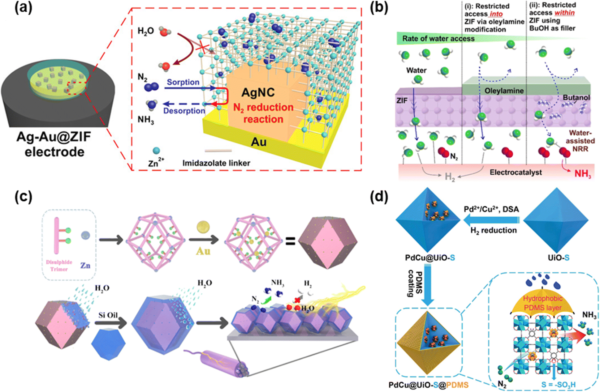 | ||
| Fig. 3 Methods for introducing hydrophobicity: (a) schematic illustration of Ag nanocubes deposited on the Au electrode followed by covering with ZIF-71. Adapted with permission from ref. 92. Copyright 2018, The American Association for the Advancement of Science. (b) M@ZIF-Oam electrocatalyst prepared by utilizing ZIF-71 for coating the metallic electrocatalysts followed by modifying OAm to impart hydrophobicity. Adapted with permission from ref. 93. Copyright 2020, American Chemical Society. (c) HT Au@MOF prepared by inserting AuNPs as guests inside the MOF pores followed by covering the MOF surface with organosilicon. Adapted with permission from ref. 94. Copyright 2021, Elsevier B.V. (d) PdCu@UiO-S@PDMS prepared by encapsulating PdCu NPs into the pores of UiO-S followed by coating with hydrophobic PDMS. Reprinted with permission from ref. 95. Copyright 2023, Wiley-VCH GmbH. | ||
In the following year, Li, Du and colleagues utilized a different zeolite imidazole framework, ZIF-8, to encapsulate NPG.96 The performance of this composite catalyst (termed NPG@ZIF-8) was examined by using a N2-saturated 0.1 M Na2SO4 water solution as the electrolyte. When the experiment was carried out at −0.8 V vs. RHE, the NH3 production was as high as 28.7 ± 0.9 μg h−1 cm−2. On the other hand, the highest FE obtained was 44% and the selectivity of ammonia was 98% at −0.6 V vs. RHE (Fig. 4a). NPG@ZIF-8 also displayed brilliant stability even if it was exposed to a constant potential of −0.6 V vs. RHE for 12 h, showing only a marginal decrease in current density.
 | ||
| Fig. 4 Catalytic performances of different electrocatalysts in terms of the NH3 yield rate and FE: (a) NPG encapsulated into ZIF-8 (NPG@ZIF-8). Adapted with permission from ref. 96. Copyright 2019, John Wiley and Sons. (b) Cu-MOF and Ce-MOF grown on the surface of copper mesh (Cu@Cu-MOF and Cu@Ce-MOF). Adapted with permission from ref. 79. Copyright 2021, American Chemical Society. (c) Polyoxometalate-based MOFs (FexCoyMOF-P2W18 and FexCoyMOF). Adapted with permission from ref. 88. Copyright 2023, Wiley-VCH GmbH. (d) UiO-66 that was made defective by introducing HPMo (UiO-66-xHPMo). Adapted with permission from ref. 82. Copyright 2024, Elsevier B.V. (e) Zn-N2S2-MOF, Zn-N3S-MOF, and Zn-N4-MOF. Adapted with permission from ref. 84. Copyright 2023, Wiley-VCH GmbH. (f) xAu/MIL-101(Fe), x = 5, 10, 15 or 20%. Adapted with permission from ref. 97. Copyright 2024 Wiley-VCH GmbH. | ||
ZIF-71 composite catalysts with different catalysts incorporated inside have also been presented. A study by Ling et al. reported the use of ZIF-71 for encapsulating PtNSs on Au electrodes (referred to as Pt/Au@ZIF).98 The electrolyte was an anhydrous THF solution containing LiCF3SO3 with 1 wt% ethanol serving as a proton source. First, PtNS size dependence was confirmed, and the results showcased that the smaller PtNSs ranging from 60 nm to 231 nm exhibited higher FE and NH3 yield rates. Second, the NRR performance was evaluated by utilizing 60 nm Pt/Au@ZIF at various potentials from −1.7 V to −3.3 V vs. Ag/AgCl. Furthermore, the results revealed that the highest FE and NH3 yield rate were 44.8 ± 4.2% and 161.9 ± 16.7 μg h−1 mgcat−1, respectively under ambient conditions at −2.9 V vs. Ag/AgCl. Pt/Au@ZIF also demonstrated a FE of over 40% and an ammonia yield rate of over 130 μg h−1 mgcat−1 across a wide range of potentials. They also compared Pt/Au@ZIF with Pt/Au, Au@ZIF and dcim-Pt/Au, which was covered with monolayer of linker molecules (dcim) and the results displayed that Pt/Au@ZIF possesses the best NRR activities.
Apart from MOFs, another method that enhanced hydrophobicity was also endeavored. A study by Ling et al. utilized ZIF-71 for coating the metallic electrocatalysts and then modified OAm to impart hydrophobicity (denoted as M@ZIF-OAm) (Fig. 3b).93 Additionally, butanol molecules were added into ZIF-71 to limit the amount of accessible water molecules. First, CV measurements of M@ZIF-OAm with butanol, M@ZIF with butanol, and M@ZIF-OAm without butanol were conducted with dry THF, trifluoromethanesulfonate and 1 wt% butanol as electrolytes including 0.25 wt% water under N2 and Ar-bubbling. M@ZIF-OAm with butanol showed a reduction peak at −2.5 V vs. Ag/AgCl, indicating NRR activity. On the other hand, other two electrodes exhibited no peak at −2.5 V, and the peak at −1.3 V confirmed the occurrence of the HER. The results revealed that both coating with OAm and adding butanol were crucial for adsorbing N2 and adjusting the interaction of water molecules with the electrocatalyst. Second, the NRR of M@ZIF-OAm and M@ZIF was performed at −2.9 V for 6 hours under N2-bubbling upon varying the amount of added water. The highest ammonia yield rate and FEs in the presence of water between 0 wt% and 0.25 wt% were 45.3 ± 2.9 μg h−1 mg−1 and 18%, respectively, in the presence of 0.1 wt% water. Both values were by far higher than those observed in the absence of water. In contrast to these results, the NRR performance of uncoated M@ZIF illustrated the best NH3 production rate and FE were 21 ± 7.2 μg h−1 mg−1 and 5 ± 0.2%, respectively, under no-water conditions, which substantiated the necessity of hydrophilicity. On another note, the stability of M@ZIF-OAm was confirmed by monitoring the values of current density at −2.9 V during 80 cycles, and there was relatively no change in this value.
In 2022, the Du group prepared a 3D MOF by using Zn(II) ions and 3,3′-bis(mercapto)biphenyl-p,p′-dicarboxylic acid, followed by inserting AuNPs as guests inside the MOF pores.94 Moreover, to enhance hydrophobicity, the surface of the MOF was covered with organosilicon (PMX-200–500CS), and this substance was named HT Au@MOF (Fig. 3c). The NRR performance of HT Au@MOF achieved the highest NH3 yield and FE of 49.5 μg h−1 mgcat−1 and 60.9%, respectively, at −0.3 V vs. RHE. The high selectivity of NH3 was also established by the absence of N2H4 detection. The performance of HT Au@MOF surpassed that of Au@MOF, and the LSV tests under Ar-saturation also indicated that the current density of HT Au@MOF was strikingly lower than that of Au@MOF, which highlighted that coating organosilicon could suppress the HER. Furthermore, they implemented other three MOFs (DTU-67, 2,5-TP and MIL-101-SO3) in the same reaction. The experimental findings revealed that there is a negative correlation between the size of AuNPs and the NRR activities. The size of AuNPs that were encapsulated into MOFs in ascending order was HT Au@MOF, HT Au@DTU-67, HT Au@2,5-TP and HT Au@MIL-101-SO3. Meanwhile, the order of NRR activities in these materials followed HT Au@MOF > HT Au@DTU-67 > HT Au@2,5-TP > HT Au@MIL-101-SO3. The reaction was carried out on the surface of AuNPs, and the mechanism confirmed that the reaction progressed via the associative distal pathway because no N2H4 was observed. The stability of HT Au@MOF was also confirmed for six cycles of the NRR at −0.3 V vs. RHE with virtually no change in the NH3 yield rate and FE after the sixth catalytic run.
The Jiang group encapsulated PdCu NPs into the pores of UiO-S followed by coating with PDMS (hereinafter PdCu@UiO-S@PDMS) and used it as catalyst for the NRR.95 The PDMS coating endowed PdCu@UiO-S with hydrophobicity (Fig. 3d). PdCu@UiO-S@PDMS exhibited the highest NH3 yield rate of 20.24 μg h−1 mgcat−1 and a FE of 13.16% at −0.25 V vs. RHE. Comparative analyses of the performances of PdCu@UiO-S@PDMS, UiO-S@PDMS and Pd@UiO-S@PDMS substantiated that PdCu NPs functioned as active sites for the NRR. The study revealed that the optimal NRR performance was achieved in the presence of a 10% molar ratio of Cu in CuPd NPs. On another note, the performances of PdCu@UiO-S@PDMS and PdCu@UiO@PDMS were compared to evince the importance of –SO3H functional groups, showing the superiority of PdCu@UiO-S@PDMS over PdCu@UiO@PDMS. To assess hydrophobicity, the contact angles of PdCu@UiO-S and PdCu@UiO-S@PDMS were determined to be 2.2° and 137.3°, respectively, which illustrated that coating PDMS enhanced the hydrophobicity, which eventually impeded the HER. Furthermore, PdCu@UiO-S@PDMS featured high selectivity and stability.
The Yin group loaded Au NPs on MIL-101(Fe) to boost its electrocatalytic activity for the NRR.97 The ratio of AuNPs and MIL-101(Fe) was changed and the compounds were termed xAu/MIL-101(Fe), x = 5, 10, 15 or 20%. Among xAu/MIL-101 (Fe), 15%Au/MIL-101 (Fe) exhibited the best performance with the highest NH3 yield rate of 46.37 μg h−1 mgcat−1 and a FE of 39.98% at −0.4 V vs. RHE (Fig. 4f). The NRR activity was also inspected by changing the potential, which revealed that the NRR performance was highest at −0.4 V owing to the strongest absorbance intensity at −0.4 V. Au NPs demonstrated high HER activity but due to the increased N2 concentration provided by MIL-101(Fe), the NRR activity was dramatically enhanced by hindering the HER pathway.
MOF composites combining MOFs and carbon materials were also explored. A study on MOFs with CNTs for the NRR was reported by Ding et al. in the same year.99 In this contribution, four MOFs (UIO-66, BIT-58, CAU-17 and MIL-101(Fe)) were utilized for inserting CNTs and N-doped CNTs (hereinafter CNT/NCNT@MOF), and all electrical measurements were done in 0.05 M H2SO4. All of the MOF compounds featured markedly superior NRR activities compared to pristine CNTs and NCNTs. From these results, MOFs contributed to hydrophobic suppression of the HER and enrichment of N2. On another note, CNT@MOFs preserved their crystallinity after six cycles, which suggested that CNT@MOFs have notable stabilities.
Other MOF and CNT compounds are also utilized as NRR catalysts. Yin and co-workers prepared UiO-66-NH2 deposited on CNTs (UiO-66-NH2/CNT-X, where X denotes the amount of CNTs used to synthesize the composite: 0.05, 0.10, 0.15 or 0.20 g) and used them as NRR catalysts.100 A 0.1 M Na2SO4 solution was used as the electrolyte and MOF/CNT composites served as working electrodes. All results of the NRR showed that UiO-66-NH2/CNT-0.15 achieved the highest NH3 yield rate of 1.854 × 10⁻¹⁰ mol s−1 cm−2 (FE: 37.38%), whereas UiO-66-NH2/CNT-0.05 showed the best FE of 45.51% (NH3 yield rate: 1.091 × 10⁻¹⁰ mol s−1 cm−2), both at −0.3 V vs. RHE. The amount of N2H4 as a by-product of the NRR was also measured by utilizing UiO-66-NH2/CNT-0.15, and the highest yield of N2H4 was 2.84 × 10⁻¹³ mol s−1 cm−2 at −0.3 V vs. RHE, which was significantly lower than the amount of NH3. To ascertain stability, UiO-66-NH2/CNT-0.15 was recycled in chronoamperometric tests 5 times and the MOF/CNT composites demonstrated impressive stability (the relative NH3 yield rate and FE were 92.97% and 94.89%, respectively, compared with the first measurement). To monitor the reaction pathway, in situ ATR-SEIRAS was utilized, and the results confirmed the formation of hydrogenated nitrogen species (N2H1–4) on the MOF/CNT composite surface. From this fact, it was revealed that the pathway follows the associative alternating pathway.
Efforts to improve conductivity have also been made. Ren, Liu and colleagues utilized ZIF-67 that was supported on Ti3C2 (denoted as ZIF-67@Ti3C2) for the NRR.101 The performance of ZIF-67@Ti3C2 was measured in 0.1 M KOH and the highest NH3 production rate and FE were 6.52 μmol h−1 cm−2 and 20.2%, respectively, at −0.4 V vs. RHE. For comparative analysis, control experiments were also performed with individual ZIF-67 and Ti3C2, which revealed that the NH3 yields were 1.61 μmol h−1 cm−2 and 2.77 μmol h−1 cm−2 for ZIF-67 and Ti3C2, respectively.
Moreover, composites including MOFs and sulfide materials were also adopted as catalysts for the NRR. A study by the Wang group adopted ZIF-71 for encapsulation of the MoS2 nanoflower (hereinafter MoS2@ZIF-71), which enhanced the NRR activity in comparison to both of the pristine materials.102 CP covered with MoS2@ZIF-71 achieved the highest NH3 production rate of 56.69 μg h−1 mgMoS2−1 and the FE was 30.91% at −0.2 V vs. RHE. These results also highlighted the contributory role of the MOF coating as a hydrophobic barrier to restrain the HER.
Lang and co-workers prepared the MIL-101(Fe)/MoS3 composite for use as an NRR catalyst.103 The best NRR performance was achieved with an NH3 yield rate and FE of 25.7 μg h−1 mgcat−1 and 36.71%, respectively, at −0.1 V vs. RHE, which exceeded those of MIL-101(Fe) (9.38 μg h−1 mgcat−1 and 13.39%) and MoS3 (0.75 μg h−1 mgcat−1 and 0.03%). From the standpoint of the conversion rate from N2 to NH3, MIL-101(Fe)/MoS3 furnished almost no N2H4 by-product from the NRR. Additionally, MIL-101(Fe)/MoS3 showed outstanding stability during five cycles and electrolysis for 12 h at −0.1 V vs. RHE, which was assessed by X-ray photoelectron spectroscopy (XPS) measurements.
In addition to the composites mentioned before, composites based on MOFs and oxides were also leveraged as electrocatalysts for the NRR. Li, Lin and colleagues prepared ZIF-8 and combined it with CeO2 nanorods, which were synthesized by calcining Ce-MOF, (hereinafter CeO2-ZIF-8), and the CeO2-ZIF-8 dispersion was applied to CP and subsequently used as the NRR electrode.104 The NRR performance showcased the highest NH3 yield rate and FE of 2.12 μg h−1 cm−2 and 8.41% at −0.5 V vs. RHE, respectively. The stability of CeO2-ZIF-8 was validated through recycling tests. After the sixth cycle, the NH3 yield rate and FE were 2.10 μg h−1 cm−2 (99.06% compared with the first cycle) and 8.21% (97.62% compared with the first cycle), which implied exceptional stability. Furthermore, when the NRR activity was measured, no N2H4 by-product could be traced, which confirmed the high selectivity towards NH3.
In the preceding discussion, numerous MOFs that have been employed hitherto as electrocatalysts for the NRR have been highlighted. The performance of different MOF electrocatalysts in the NRR is summarized in Table 1. Striving for better NRR activities, scientists not only adopted a diverse range of metals and linkers to construct MOFs but also introduced defects to facilitate accessibility of the active sites. Besides, other materials like CNTs, MXenes, etc. have been used to prepare composites with MOFs for synergistic enhancement of electrocatalytic activities. On another note, MOFs have also been utilized as coatings on other electrocatalysts to impart hydrophobicity, thereby suppressing the HER, which is one of the factors impeding the NRR.
| Year | Electrocatalysts | NH3 yield rate | Potential/current density | Ref. |
|---|---|---|---|---|
| 2017 | MOF (Fe) | 2.12 × 10⁻⁹ mol s−1 cm−2 | −1.2 V vs. Ag/AgCl | 74 |
| MOF (Co) | 1.64 × 10⁻⁹ mol s−1 cm−2 | −1.2 V vs. Ag/AgCl | 74 | |
| MOF (Cu) | 1.24 × 10⁻⁹ mol s−1 cm−2 | −1.2 V vs. Ag/AgCl | 74 | |
| 2018 | Ag–Au@ZIF | ∼10 pmol s−1 cm−2 | −2.9 V vs. Ag/AgCl | 92 |
| 2019 | NPG@ZIF-8 | 28.7 ± 0.9 μg h−1 cm−2 | −0.8 V vs. RHE | 96 |
| JUC-1000/CC | 24.7 μg h−1 mgcat−1 | 0.4 V vs. Ag/AgCl | 75 | |
| 2020 | Co3Fe-MOF | 8.79 μg h−1 mgcat−1 | −0.2 V vs. RHE | 85 |
| NiFe-MOF | 9.3 μg h−1 mgcat−1 | −345 mV vs. RHE | 86 | |
| MIL-100(Al) | 43.15 μg h−1 mgcat−1 | −0.7 V vs. RHE | 71 | |
| NH2-MIL-88B-Fe | 1.205 × 10⁻¹⁰ mol s−1 cm−2 | −0.45 V vs. RHE | 76 | |
| Pt/Au@ZIF | 161.9 ± 16.7 μg h−1 mgcat−1 | −2.9 V vs. Ag/AgCl | 98 | |
| Co3(HHTP)2/CP | 22.14 μg h−1 mgcat−1 | −0.40 V vs. RHE | 77 | |
| HKUST-1/CP | 46.63 μg h−1 mgcat−1 | −0.75 V vs. RHE | 78 | |
| M@ZIF-Oam | 45.3 ± 2.9 μg h−1 mgcat−1 | −2.9 V vs. Ag/AgCl | 93 | |
| 2021 | Cu@Cu-MOF | 10.23 μg h−1 cm−2 | −0.2 V vs. RHE | 79 |
| Cu@Ce-MOF | 14.83 μg h−1 cm−2 | −0.2 V vs. RHE | 79 | |
| CNT@UiO-66 | 3.811 μg h−1 mgcat−1 | −0.55 V vs. RHE | 99 | |
| NCNT@UiO-66 | 6.081 μg h−1 mgcat−1 | −0.6 V vs. RHE | 99 | |
| CNT@BIT-58 | 4.135 μg h−1 mgcat−1 | −0.45 V vs. RHE | 99 | |
| NCNT@BIT-58 | 8.108 μg h−1 mgcat−1 | −0.45 V vs. RHE | 99 | |
| CNT@CAU-17 | 11.92 ± 0.083 μg h−1 mgcat−1 | −0.45 V vs. RHE | 99 | |
| NCNT@CAU-17 | 13.30 ± 0.01 μg h−1 mgcat−1 | −0.45 V vs. RHE | 99 | |
| CNT@MIL-101(Fe) | 5.514 μg h−1 mgcat−1 | −0.45 V vs. RHE | 99 | |
| NCNT@MIL-101(Fe) | 6.97 μg h−1 mgcat−1 | −0.45 V vs. RHE | 99 | |
| Fe-TCPP | 44.77 μg h−1 mgcat−1 | −0.3 V vs. RHE | 90 | |
| Co-TCPP | 28.3 μg h−1 mgcat−1 | −0.3 V vs. RHE | 90 | |
| Zn-TCPP | 19.59 μg h−1 mgcat−1 | −0.3 V vs. RHE | 90 | |
| UiO–Zr–Ti | 1.16 ± 0.058 × 10⁻¹⁰ mol s−1 cm−2 | −0.3 V vs. RHE | 87 | |
| ZIF-67@Ti3C2 | 6.52 μmol h−1 cm−2 | −0.4 V vs. RHE | 101 | |
| MoS2@ZIF-71 | 56.69 μg h−1 mgMoS2−1 | −0.2 V vs. RHE | 102 | |
| 2D In-MOF | 79.20 μg h−1 mgcat−1 | −0.5 mA cm−2 | 80 | |
| 2022 | HT Au@MOF | 49.5 μg h−1 mgcat−1 | −0.3 V vs. RHE | 94 |
| Defective UiO-66-NH2 | ∼2.071 × 10⁻¹⁰ mol s−1 cm−2 | −0.39 V vs. RHE | 81 | |
| MIL-101(Fe)/MoS3 | 25.7 μg h−1 mgcat−1 | −0.1 V vs. RHE | 103 | |
| CeO2-ZIF-8 | 2.12 μg h−1 cm−2 | −0.5 V vs. RHE | 104 | |
| 2023 | FeCoMOF-P2W18 | 47.04 μg h−1 mgcat−1 | −0.4 V vs. RHE | 88 |
| PdCu@UiO-S@PDMS | 20.24 μg h−1 mgcat−1 | −0.25 V vs. RHE | 95 | |
| UiO-66-NH2/CNT-0.15 | 1.854 × 10⁻¹⁰ mol s−1 cm−2 | −0.3 V vs. RHE | 100 | |
| 2024 | UiO-66-2HPMO | 36.61 μg h−1 mgcat−1 | −0.3 V vs. RHE | 82 |
| Defective Al-Fum | 53.9 μg h−1 mgcat−1 | −0.15 V vs. RHE | 83 | |
| Zn-N2S2-MOF | 25.07 ± 1.57 μg h−1 cm−2 | −0.3 V vs. RHE | 84 | |
| 15% Au/MIL-101(Fe) | 46.37 μg h−1 mgcat−1 | −0.4 V vs. RHE | 97 | |
| CoFe-MIL-88A/V2CTx | 29.47 μg h−1 mgcat−1 | −0.3 V vs. RHE | 89 | |
| PCN-224-Ni(F) | 0.9 μg h−1 mgcat−1 | −0.04 V vs. RHE | 91 |
4.4. MOF-derived electrocatalysts for the NRR
The stability of pristine MOFs sometimes raises concerns about their utilization as electrocatalysts due to which MOF-derived electrocatalysts have gained prominence. MOF-derived carbons are promising catalysts for the eNRR, attributed to their remarkable surface areas, customizable functionalities and tailorable pore configuration. Wang, Wu and co-workers adopted a ZIF-8-derived disordered and porous N-doped carbon as a catalyst for the eNRR that presented a noteworthy NH3 generation rate of 3.4 × 10⁻⁶ mol cm−2 h−1 and a FE of 10.2% at −0.3 V vs. RHE at room temperature and ambient pressure.105 The NH3 generation rate reached 7.3 × 10⁻⁶ mol cm−2 h−1 upon raising the temperature to 60 °C. N-codoped porous carbon with other heteroatoms such as P, B and S also gained attention as efficient NRR electrocatalysts. A study by Song et al. demonstrated that N, P co-doped carbon obtained from MOF-5 through pyrolysis served as a highly efficient NRR electrocatalyst that gave NH3 and N2H4·H2O yields of 1.08 and 5.77 × 10⁻⁴ μg h−1 mgcat−1, respectively, at −0.1 V vs. RHE.106 In a similar study by Wang et al., a N, P co-doped carbon prepared by controlling the competition between the N source (ZIF-8) and P source (triphenylphosphine) demonstrated its effectiveness as an NRR electrocatalyst with an impressive NH3 yield of 33.02 μg h−1 mgcat−1 and a FE of 7.19% at −0.3 V vs. RHE.107 MOF-derived single metal atom catalysts also garnered significant attention as NRR electrocatalysts. A study by Si, Zeng and colleagues reported Ru single atoms distributed on N-doped carbon developed by pyrolyzing a Ru-containing derivative of ZIF-8 that achieved a superb NH3 yield of 120.9 μg h−1 mgcat−1 and a FE of 29.6% at −0.2 V vs. RHE.108 Luo, Tang, Liu and colleagues presented an Fe single atom catalyst developed from bimetallic Fe/Zn ZIF-8 through carbonization and etching.109 The electrocatalyst displayed an NH3 generation rate of 62.9 ± 2.7 μg h−1 mgcat−1 and a FE of 18.6 ± 0.8%, respectively. In addition, metal nanoparticles confined in MOF derived-carbon rods also displayed their efficiency as NRR electrocatalysts. A study by Zheng, Du, Sun and co-workers showcased Bi nanoparticles confined in carbon rods (Bi NPs@CRs), prepared through thermal annealing of a Bi-MOF precursor, which delivered an NH3 production rate of 20.80 μg h−1 mgcat−1 and a FE of 11.50% at −0.60 and −0.55 V vs. RHE, respectively.1105. Future directions and challenges
Following is the mainstay for future studies on MOFs as electrocatalysts for the NRR.5.1. Durability
In electrocatalytic applications, durability is a pivotal parameter for any material platform and the same pertains to MOFs as well. When MOFs are utilized as heterogeneous electrocatalysts supported onto electrodes for the NRR, it is imperative that the MOF should not dissolve in the electrolyte. This leakage can be assessed by detecting the metal ions that constitute the MOFs in the post-reaction electrolyte by conducting some measurements such as ICP-MS. Besides, the electrochemical stability can be evaluated by monitoring changes during prolonged constant voltage and its recyclability though the same reaction. Moreover, confirming the structure and state of MOFs after use as electrocatalysts via powder X-ray diffraction (PXRD) analysis for validating the retention of the crystalline structure, electron microscopy for examining the morphology, XPS and XAFS for observing the oxidation states is crucial to substantiate its long-term operational capacity.5.2. Mechanism
A thorough comprehension of heterogeneous electrocatalytic NRR mechanisms can provide deeper insights into designing new MOF electrocatalysts. Nevertheless, the details and specifics of heterogeneous electrochemistry in most literature studies are insufficient. To accomplish this, in situ and in operando monitoring of intermediates and transition states in heterogeneous electrocatalysis might elucidate the chemistry underpinning it. It can be worthwhile to harness machine learning for streamlining optimal MOFs. Furthermore, cost-efficiency is a key factor to consider during the design of a catalyst. While noble metal-based MOFs may exhibit high activity, their cost might eventually surpass their performance benefits. Therefore, using non-noble metals is highly desirable, especially from the perspective of economic viability.5.3. Technological hurdles towards commercialization
Several companies in the world are leveraging the unique properties of MOFs to introduce as new porous materials into the market. However, in order to commercialize MOFs as electrocatalysts into the market, several challenges must be addressed. For commercialization, stability under redox conditions is one of the most critical metrics. In practical scenario, catalysts that degrade after only a few cycles cannot be considered cost-effective for long-term operation. For this reason, MOFs must possess high stability to be viable for commercial use. Furthermore, the heterogeneity of MOFs should be preserved. If metal ions leach during reactions, the method for collecting them needs to be considered, which incurs additional costs. Therefore, it is essential that even after conducting many cycles, remarkable metal ions should not be observed. The second thing is scalability. To expand the market for MOFs, they need to be synthesized on a kilogram scale with adequate safety.5.4. Improving MOFs' electrocatalytic activity for the NRR
The first requirement for enhancing the NRR catalytic performance of MOFs is to achieve a suitable level of hydrophobicity. This is due to the fact that the HER, which suppresses the NRR, becomes more favorable in a hydrophilic environment. Therefore, it is essential to manage the reaction conditions to minimize the occurrence of the HER. To establish an optimal hydrophobic state, one approach is to introduce hydrophobic functional groups into the MOF structure. Another essential factor for improving the NRR activity is the optimization of the active sites: purposely creating defect structures or utilizing multiple metals, as highlighted in previous discussion. In addition to these approaches, it is also believed that the use of multivariate MOFs can further enhance NRR catalytic activity. As demonstrated here, there are still some factors that can contribute to increasing the electrocatalytic activity of MOFs for the NRR. These suggestions possess the potential to guide the design of MOFs with higher catalytic activity in the future.5.5. Standardization
As noted in this review, the activities of MOFs are evaluated at various voltages where the highest performance is obtained. However, without the standardization of such parameters, comparing the activities of these MOFs is inappropriate and a lack of uniformity in measurement conditions persists. Therefore, it is necessary to standardize some parameters such as the amount of catalyst, the kind and amount of electrolyte, counter electrode, voltage, the method of NH3 detection, etc., which will lead to proper evaluation.6. Concluding remarks
To sum up, MOFs have come to the fore as potential electrocatalysts for the NRR due to their structural tailorability and variety, extensive porosity and controllability over catalytically active sites. The pore space of MOFs can be harnessed to enhance reduction activity. Considerable research has been devoted to the enhancement of N2 adsorption capacity, introduction of redox-active sites, and boosting the reaction kinetics. Future research can be directed towards a deeper understanding of the mechanism, which in turn can lead towards the rational design of heterogeneous MOF catalysts.Author contributions
R. N.: information collection, writing original draft and editing; S. D.: conceptualization, supervision, review and editing; Y. N.: conceptualization, supervision, review and editing.Conflicts of interest
The authors declare no competing financial interest.Abbreviations
| NiRux-BDC | Ru-introduced Ni2(OH)2(C8H4O4); |
| BTC | Benzene-1,3,5-tricarboxylate; |
| NiCo-UMOFN | Ni and Co ultrathin MOF nanosheet; |
| CoBDC | Co2(OH)2(C8H4O4); |
| Fc | Carboxyferrocene; |
| Cu-BTC | Cu3(BTC)2(H2O)x; |
| Cu-bipy-BTC | [Cu2(OH)(bipy)2(BTC)3·2H2O]n; |
| Bipy | 2,2′-Bipyridine; |
| HITP | 2,3,6,7,10,11-Hexaiminotriphenylene; |
| BmimBF4 | 1-Butyl-3-methylimidazolium tetrafluoroborate; |
| BmimOTf | 1-Butyl-3-methylimidazolium trifluoromethanesulfonate; |
| BmimPF6 | 1-Butyl-3-methylimidazolium hexafluorophosphate; |
| BmimClO4 | 1-Butyl-3-methylimidazolium perchlorate; |
| MvK | Mars-van Krevelen; |
| TMN | Transition metal nitrides; |
| EDTA | Ethylenediaminetetraacetic acid; |
| LiCF3SO3 | Lithium trifluoromethanesulfonate; |
| RHE | Reversible hydrogen electrode; |
| NPG | Nanoporous gold; |
| SG | Sodium gluconate; |
| GA | Glucaric acid; |
| NiFe-MOF | Ni0.81Fe0.19((C12H6O4)(H2O)4); |
| PtNS | Pt nanosphere; |
| HHTP | 2,3,6,7,10,11-Hexahydroxytriphenylene; |
| OAm | Oleylamine; |
| CNT | Carbon nanotube; |
| AuNPs | Au nanoparticles; |
| FexCoyMOF-P2W18 | [FexCoy(Pbpy)9(ox)6(H2O)6][P2W18O62]·3H2O; |
| UiO-S | UiO-66-SO3; |
| PDMS | Polydimethylsiloxane; |
| Al-Fum MOF | Aluminum-fumarate MOF; |
| HPMo | Phosphomolybdic acid |
Acknowledgements
This study received financial support from the Scientific Research on Innovative Areas “Aquatic Functional Materials” (grant no. 22H04562), the Japan Society for the Promotion of Science (JSPS) KAKENHI (grant no. 20H02698, 22K19012, and 23H00289), the Yazaki Memorial Foundation for Science and Technology, and the Ogasawara Foundation for the Promotion of Science and Engineering.References
- O. M. Yaghi, G. Li and H. Li, Nature, 1995, 378, 703–706 CrossRef.
- M. Kondo, T. Yoshitomi, H. Matsuzaka, S. Kitagawa and K. Seki, Angew. Chem., Int. Ed. Engl., 1997, 36, 1725–1727 CrossRef.
- H.-C. Zhou, J. R. Long and O. M. Yaghi, Chem. Rev., 2012, 112, 673–674 CrossRef PubMed.
- Z. Chen, K. O. Kirlikovali, P. Li and O. K. Farha, Acc. Chem. Res., 2022, 55, 579–591 CrossRef PubMed.
- H. Furukawa, K. E. Cordova, M. O'Keeffe and O. M. Yaghi, Science, 2013, 341, 1230444 CrossRef PubMed.
- S. Kitagawa and R. Matsuda, Coord. Chem. Rev., 2007, 251, 2490–2509 CrossRef CAS.
- S. Qiu, M. Xue and G. Zhu, Chem. Soc. Rev., 2014, 43, 6116–6140 RSC.
- R. C. Huxford, J. Della Rocca and W. Lin, Curr. Opin. Chem. Biol., 2010, 14, 262–268 CrossRef CAS PubMed.
- W. Xu and O. M. Yaghi, ACS Cent. Sci., 2020, 6, 1348–1354 CrossRef CAS PubMed.
- P. Horcajada, R. Gref, T. Baati, P. K. Allan, G. Maurin, P. Couvreur, G. Férey, R. E. Morris and C. Serre, Chem. Rev., 2012, 112, 1232–1268 CrossRef CAS PubMed.
- L. E. Kreno, K. Leong, O. K. Farha, M. Allendorf, R. P. Van Duyne and J. T. Hupp, Chem. Rev., 2012, 112, 1105–1125 CrossRef CAS PubMed.
- M. Kurmoo, Chem. Soc. Rev., 2009, 38, 1353–1379 RSC.
- D.-W. Lim and H. Kitagawa, Chem. Rev., 2020, 120, 8416–8467 CrossRef CAS.
- S. Majumdar, S. M. Moosavi, K. M. Jablonka, D. Ongari and B. Smit, ACS Appl. Mater. Interfaces, 2021, 13, 61004–61014 CrossRef CAS.
- S. M. Rogers, C. R. A. Catlow, D. Gianolio, P. P. Wells and N. Dimitratos, Faraday Discuss., 2018, 208, 443–454 RSC.
- G.-G. Luo, Z.-H. Pan, B.-L. Han, G.-L. Dong, C.-L. Deng, M. Azam, Y.-W. Tao, J. He, C.-F. Sun and D. Sun, Angew. Chem., Int. Ed., 2023, 62, e202306849 CrossRef CAS PubMed.
- Z. Chen, E. Vorobyeva, S. Mitchell, E. Fako, M. A. Ortuño, N. López, S. M. Collins, P. A. Midgley, S. Richard, G. Vilé and J. Pérez-Ramírez, Nat. Nanotechnol., 2018, 13, 702–707 CrossRef CAS.
- Y. Zhao, K. R. Yang, Z. Wang, X. Yan, S. Cao, Y. Ye, Q. Dong, X. Zhang, J. E. Thorne, L. Jin, K. L. Materna, A. Trimpalis, H. Bai, S. C. Fakra, X. Zhong, P. Wang, X. Pan, J. Guo, M. Flytzani-Stephanopoulos, G. W. Brudvig, V. S. Batista and D. Wang, Proc. Natl. Acad. Sci. U.S.A., 2018, 115, 2902–2907 CrossRef CAS PubMed.
- A. Corma, L. T. Nemeth, M. Renz and S. Valencia, Nature, 2001, 412, 423–425 CrossRef CAS PubMed.
- N. S. Ali, Z. T. Alismaeel, H. S. Majdi, H. G. Salih, M. A. Abdulrahman, N. M. Cata Saady and T. M. Albayati, Heliyon, 2022, 8, e09737 CrossRef CAS.
- R. Nakatani, S. Biswas, T. Irie, J. Sakai, D. Hirayama, T. Kawawaki, Y. Niihori, S. Das and Y. Negishi, Nanoscale, 2023, 15, 16299–16306 RSC.
- Q. Fang, S. Gu, J. Zheng, Z. Zhuang, S. Qiu and Y. Yan, Angew. Chem., Int. Ed., 2014, 53, 2878–2882 CrossRef.
- A. Corma, Faraday Discuss., 2016, 188, 9–20 RSC.
- D. Bao, Q. Zhang, F.-L. Meng, H.-X. Zhong, M.-M. Shi, Y. Zhang, J.-M. Yan, Q. Jiang and X.-B. Zhang, Adv. Mater., 2017, 29, 1604799 CrossRef.
- J. Humphreys, R. Lan and S. Tao, Adv. Energy Sustainability Res., 2021, 2, 2000043 CrossRef.
- K. H. R. Rouwenhorst, A. G. J. Van der Ham and L. Lefferts, Int. J. Hydrogen Energy, 2021, 46, 21566–21579 CrossRef CAS.
- D. Liu, M. Chen, X. Du, H. Ai, K. H. Lo, S. Wang, S. Chen, G. Xing, X. Wang and H. Pan, Adv. Funct. Mater., 2021, 31, 2008983 CrossRef CAS.
- Y. Yao, H. Wang, X.-z. Yuan, H. Li and M. Shao, ACS Energy Lett., 2019, 4, 1336–1341 CrossRef CAS.
- X. Guo, H. Du, F. Qu and J. Li, J. Mater. Chem. A, 2019, 7, 3531–3543 RSC.
- Y. H. Moon, N. Y. Kim, S. M. Kim and Y. J. Jang, Catalysts, 2022, 12, 1015 CrossRef CAS.
- K. Liu, P. Cao, W. Chen, C. I. Ezeh, Z. Chen, Y. Luo, Q. Liu, H. Zhao, Z. Rui, S. Gao, Z. Yin, X. Sun and X. Yu, Mater. Adv., 2022, 3, 1359–1400 RSC.
- R. Akter, S. S. Shah, M. A. Ehsan, M. N. Shaikh, M. H. Zahir, M. A. Aziz and A. J. S. Ahammad, Chem.–Asian J., 2024, 19, e202300797 CrossRef CAS PubMed.
- X. Wen and J. Guan, Nanoscale, 2020, 12, 8065–8094 RSC.
- W. Xiong, H. Yin, T. Wu and H. Li, Chem.–Eur. J., 2023, 29, e202202872 CrossRef CAS PubMed.
- Q. Zhang and J. Guan, Adv. Funct. Mater., 2020, 30, 2000768 CrossRef CAS.
- W. Zhang, J. Low, R. Long and Y. Xiong, EnergyChem, 2020, 2, 100040 CrossRef.
- Y. Peng, S. Sanati, A. Morsali and H. García, Angew. Chem., Int. Ed., 2023, 62, e202214707 CrossRef CAS PubMed.
- L. Sun, M. G. Campbell and M. Dincă, Angew. Chem., Int. Ed., 2016, 55, 3566–3579 CrossRef CAS.
- S. K. Bhardwaj, N. Bhardwaj, R. Kaur, J. Mehta, A. L. Sharma, K.-H. Kim and A. Deep, J. Mater. Chem. A, 2018, 6, 14992–15009 RSC.
- H. He, H.-M. Wen, H.-K. Li and H.-W. Zhang, Coord. Chem. Rev., 2022, 471, 214761 CrossRef CAS.
- Y. Zhu, H. Ji, T. Huang, Y. Sun and H. Pang, Adv. Sustainable Syst., 2024, 2400225 CrossRef.
- Z. Zhu, J. Duan and S. Chen, Small, 2024, 20, 2309119 Search PubMed.
- I. E. Khalil, C. Xue, W. Liu, X. Li, Y. Shen, S. Li, W. Zhang and F. Huo, Adv. Funct. Mater., 2021, 31, 2010052 CrossRef.
- X. Han, S. Yang and M. Schröder, J. Am. Chem. Soc., 2023, 145, 1998–2012 CrossRef.
- Y. Yu, Y. Li, Y. Fang, L. Wen, B. Tu and Y. Huang, Appl. Catal., B, 2024, 340, 123161 CrossRef.
- L. Tang, Q. Xu, Y. Zhang, W. Chen and M. Wu, Electrochem. Energy Rev., 2022, 5, 32–81 CrossRef.
- B. Nohra, H. El Moll, L. M. Rodriguez Albelo, P. Mialane, J. Marrot, C. Mellot-Draznieks, M. O'Keeffe, R. Ngo Biboum, J. Lemaire, B. Keita, L. Nadjo and A. Dolbecq, J. Am. Chem. Soc., 2011, 133, 13363–13374 CrossRef CAS.
- W. R. McNamara, Z. Han, P. J. Alperin, W. W. Brennessel, P. L. Holland and R. Eisenberg, J. Am. Chem. Soc., 2011, 133, 15368–15371 CrossRef CAS.
- A. J. Clough, J. W. Yoo, M. H. Mecklenburg and S. C. Marinescu, J. Am. Chem. Soc., 2015, 137, 118–121 CrossRef CAS PubMed.
- Y. Sun, Z. Xue, Q. Liu, Y. Jia, Y. Li, K. Liu, Y. Lin, M. Liu, G. Li and C.-Y. Su, Nat. Commun., 2021, 12, 1369 CrossRef.
- K. F. Babu, M. A. Kulandainathan, I. Katsounaros, L. Rassaei, A. D. Burrows, P. R. Raithby and F. Marken, Electrochem. Commun., 2010, 12, 632–635 CrossRef.
- S. Zhao, Y. Wang, J. Dong, C.-T. He, H. Yin, P. An, K. Zhao, X. Zhang, C. Gao, L. Zhang, J. Lv, J. Wang, J. Zhang, A. M. Khattak, N. A. Khan, Z. Wei, J. Zhang, S. Liu, H. Zhao and Z. Tang, Nat. Energy, 2016, 1, 16184 CrossRef.
- Z. Xue, K. Liu, Q. Liu, Y. Li, M. Li, C.-Y. Su, N. Ogiwara, H. Kobayashi, H. Kitagawa, M. Liu and G. Li, Nat. Commun., 2019, 10, 5048 CrossRef PubMed.
- J. Mao, L. Yang, P. Yu, X. Wei and L. Mao, Electrochem. Commun., 2012, 19, 29–31 CrossRef.
- E. M. Miner, T. Fukushima, D. Sheberla, L. Sun, Y. Surendranath and M. Dincă, Nat. Commun., 2016, 7, 10942 CrossRef.
- Z. Liang, H. Guo, G. Zhou, K. Guo, B. Wang, H. Lei, W. Zhang, H. Zheng, U.-P. Apfel and R. Cao, Angew. Chem., Int. Ed., 2021, 60, 8472–8476 CrossRef CAS PubMed.
- R. Hinogami, S. Yotsuhashi, M. Deguchi, Y. Zenitani, H. Hashiba and Y. Yamada, ECS Electrochem. Lett., 2012, 1, H17 CrossRef CAS.
- X. Kang, Q. Zhu, X. Sun, J. Hu, J. Zhang, Z. Liu and B. Han, Chem. Sci., 2016, 7, 266–273 RSC.
- Y.-L. Qiu, H.-X. Zhong, T.-T. Zhang, W.-B. Xu, P.-P. Su, X.-F. Li and H.-M. Zhang, ACS Appl. Mater. Interfaces, 2018, 10, 2480–2489 CrossRef CAS.
- L. Yang, S. Kinoshita, T. Yamada, S. Kanda, H. Kitagawa, M. Tokunaga, T. Ishimoto, T. Ogura, R. Nagumo, A. Miyamoto and M. Koyama, Angew. Chem., Int. Ed., 2010, 49, 5348–5351 CrossRef CAS.
- H. Gu, W. Chen and X. Li, J. Mater. Chem. A, 2022, 10, 22331–22353 RSC.
- S. Y. Park, Y. J. Jang and D. H. Youn, Catalysts, 2023, 13, 639 CrossRef.
- W. T. Bolleter, C. J. Bushman and P. W. Tidwell, Anal. Chem., 1961, 33, 592–594 Search PubMed.
- C. J. Patton and S. Crouch, Anal. Chem., 1977, 49, 464–469 CrossRef.
- D. Scheiner, Water Res., 1976, 10, 31–36 CrossRef.
- T. Tsuboi, Y. Hirano, Y. Shibata and S. Motomizu, Anal. Sci., 2002, 18, 1141–1144 CrossRef CAS PubMed.
- M. Nichols and C. Willits, J. Am. Chem. Soc., 1934, 56, 769–774 CrossRef CAS.
- A. Vanselow, Ind. Eng. Chem., Anal. Ed., 1940, 12, 516–517 CrossRef CAS.
- H. Jeong, J. Park and H. Kim, J. Chem., 2013, 2013, 359217 CrossRef.
- F. C. Koch and T. L. McMeekin, J. Am. Chem. Soc., 1924, 46, 2066–2069 CrossRef CAS.
- Y. Fu, K. Li, M. Batmunkh, H. Yu, S. Donne, B. Jia and T. Ma, ACS Appl. Mater. Interfaces, 2020, 12, 44830–44839 CrossRef CAS.
- S. Chen, S. Perathoner, C. Ampelli, C. Mebrahtu, D. Su and G. Centi, Angew. Chem., Int. Ed., 2017, 56, 2699–2703 CrossRef CAS PubMed.
- G. W. Watt and J. D. Chrisp, Anal. Chem., 1952, 24, 2006–2008 CrossRef CAS.
- X. Zhao, F. Yin, N. Liu, G. Li, T. Fan and B. Chen, J. Mater. Sci., 2017, 52, 10175–10185 CrossRef CAS.
- L. Zhao, X. Kuang, C. Chen, X. Sun, Z. Wang and Q. Wei, Chem. Commun., 2019, 55, 10170–10173 RSC.
- X. Yi, X. He, F. Yin, T. Yang, B. Chen and G. Li, J. Mater. Sci., 2020, 55, 12041–12052 CrossRef CAS.
- W. Xiong, X. Cheng, T. Wang, Y. Luo, J. Feng, S. Lu, A. M. Asiri, W. Li, Z. Jiang and X. Sun, Nano Res., 2020, 13, 1008–1012 CrossRef CAS.
- Y. Cao, P. Li, T. Wu, M. Liu and Y. Zhang, Chem.–Asian J., 2020, 15, 1272–1276 CrossRef CAS.
- P. Liu, P. Jing, X. Xu, B. Liu and J. Zhang, ACS Appl. Energy Mater., 2021, 4, 12128–12136 CrossRef CAS.
- Y. Sun, B. Xia, S. Ding, L. Yu, S. Chen and J. Duan, J. Mater. Chem. A, 2021, 9, 20040–20047 RSC.
- X. He, F. Yin, X. Yi, T. Yang, B. Chen, X. Wu, S. Guo, G. Li and Z. Li, ACS Appl. Mater. Interfaces, 2022, 14, 26571–26586 CrossRef CAS PubMed.
- L. Shi, P. Guo, F. Yin, A. A. M. Ahmed Al-Anzah, Z. Ni, J. Zhang, G. Li and B. Chen, Catal. Today, 2024, 433, 114662 CrossRef CAS.
- B. Han, L. Zhong, C. Chen, J. Ding, C. Lee, J. Liu, M. Chen, S. Tso, Y. Hu, C. Lv, Y. Han, B. Liu and Q. Yan, Small, 2024, 20, 2307506 CrossRef CAS.
- Y. Sun, W. Fan, Y. Li, N. L. D. Sui, Z. Zhu, Y. Zhou and J.-M. Lee, Adv. Mater., 2024, 36, 2306687 CrossRef CAS PubMed.
- W. Li, W. Fang, C. Wu, K. N. Dinh, H. Ren, L. Zhao, C. Liu and Q. Yan, J. Mater. Chem. A, 2020, 8, 3658–3666 RSC.
- J. Duan, Y. Sun, S. Chen, X. Chen and C. Zhao, J. Mater. Chem. A, 2020, 8, 18810–18815 RSC.
- J. Tan, X. He, F. Yin, X. Liang and G. Li, Int. J. Hydrogen Energy, 2021, 46, 31647–31658 CrossRef.
- M. Yang, X. Wang, C. J. Gómez-García, Z. Jin, J. Xin, X. Cao, H. Ma, H. Pang, L. Tan, G. Yang and Y. Kan, Adv. Funct. Mater., 2023, 33, 2214495 CrossRef.
- S. Li, K. Cheng, L. Ma, L. Zhang, F. Li and Q. Cheng, Inorg. Chem., 2024, 63, 8366–8375 CrossRef PubMed.
- M. Cong, X. Chen, K. Xia, X. Ding, L. Zhang, Y. Jin, Y. Gao and L. Zhang, J. Mater. Chem. A, 2021, 9, 4673–4678 RSC.
- M. Romero-Angel, R. Amrine, B. Ávila-Bolívar, N. Almora-Barrios, C. R. Ganivet, N. M. Padial, V. Montiel, J. Solla-Gullón, S. Tatay and C. Martí-Gastaldo, J. Mater. Chem. A, 2024, 12, 10956–10964 RSC.
- H. K. Lee, C. S. L. Koh, Y. H. Lee, C. Liu, I. Y. Phang, X. Han, C.-K. Tsung and X. Y. Ling, Sci. Adv., 2018, 4, eaar3208 CrossRef PubMed.
- C. S. L. Koh, H. K. Lee, H. Y. Fan Sim, X. Han, G. C. Phan-Quang and X. Y. Ling, Chem. Mater., 2020, 32, 1674–1683 CrossRef CAS.
- H. He, Q.-Q. Zhu, Y. Yan, H.-W. Zhang, Z.-Y. Han, H. Sun, J. Chen, C.-P. Li, Z. Zhang and M. Du, Appl. Catal., B, 2022, 302, 120840 CrossRef CAS.
- L. Wen, K. Sun, X. Liu, W. Yang, L. Li and H.-L. Jiang, Adv. Mater., 2023, 35, 2210669 CrossRef CAS PubMed.
- Y. Yang, S.-Q. Wang, H. Wen, T. Ye, J. Chen, C.-P. Li and M. Du, Angew. Chem., Int. Ed., 2019, 58, 15362–15366 CrossRef.
- Z. Ni, F. Yin, J. Zhang, G. Kofie, G. Li, B. Chen, P. Guo and L. Shi, Chem.–Eur. J., 2024, 30, e202401010 CrossRef PubMed.
- H. Y. F. Sim, J. R. T. Chen, C. S. L. Koh, H. K. Lee, X. Han, G. C. Phan-Quang, J. Y. Pang, C. L. Lay, S. Pedireddy, I. Y. Phang, E. K. L. Yeow and X. Y. Ling, Angew. Chem., Int. Ed., 2020, 59, 16997–17003 CrossRef PubMed.
- Y. Lv, Y. Wang, M. Yang, Z. Mu, S. Liu, W. Ding and M. Ding, J. Mater. Chem. A, 2021, 9, 1480–1486 RSC.
- S. Chen, F. Yin, X. He and J. Tan, ChemistrySelect, 2023, 8, e202204988 CrossRef.
- X. Liang, X. Ren, Q. Yang, L. Gao, M. Gao, Y. Yang, H. Zhu, G. Li, T. Ma and A. Liu, Nanoscale, 2021, 13, 2843–2848 RSC.
- J. Duan, D. Shao, X. He, Y. Lu and W. Wang, Colloids Surf., A, 2021, 619, 126529 CrossRef CAS.
- W.-Y. Xu, C. Li, F.-L. Li, J.-Y. Xue, W. Zhang, H. Gu, B. F. Abrahams and J.-P. Lang, Sci. China: Chem., 2022, 65, 885–891 CrossRef CAS.
- Y. Liu, X. Meng, Z. Zhao, K. Li and Y. Lin, Nanomaterials, 2022, 12, 2964 CrossRef CAS PubMed.
- S. Mukherjee, D. A. Cullen, S. Karakalos, K. Liu, H. Zhang, S. Zhao, H. Xu, K. L. More, G. Wang and G. Wu, Nano Energy, 2018, 48, 217–226 CrossRef CAS.
- P. Song, L. Kang, H. Wang, R. Guo and R. Wan, ACS Appl. Mater. Interfaces, 2019, 11, 12408–12414 CrossRef CAS.
- P. Wang, S. Zhao, Y. Xing, Z. Liu, Y. Xu, S. Li, S. Wang and J. Li, Microporous Mesoporous Mater., 2024, 368, 113031 CrossRef.
- Z. Geng, Y. Liu, X. Kong, P. Li, K. Li, Z. Liu, J. Du, M. Shu, R. Si and J. Zeng, Adv. Mater., 2018, 30, 1803498 CrossRef.
- F. Lü, S. Zhao, R. Guo, J. He, X. Peng, H. Bao, J. Fu, L. Han, G. Qi, J. Luo, X. Tang and X. Liu, Nano Energy, 2019, 61, 420–427 CrossRef.
- F. Wang, L. Zhang, T. Wang, F. Zhang, Q. Liu, H. Zhao, B. Zheng, J. Du and X. Sun, Inorg. Chem., 2021, 60, 7584–7589 CrossRef PubMed.
| This journal is © The Royal Society of Chemistry 2024 |