DOI:
10.1039/D3SM00846K
(Paper)
Soft Matter, 2023,
19, 7084-7092
Curvature-mediated programming of liquid crystal microflows
Received
28th June 2023
, Accepted 29th August 2023
First published on 29th August 2023
Abstract
Despite the recognized role of liquid crystal microfluidics in generating programmable, self-organized and guided flow properties, to date, the flow behavior of LCs within curved channels remains unexplored. Using experiments and numerical simulations, we demonstrate that the curvature of microscale conduits allow programming of liquid crystal (LC) flows. Focusing on a nematic LC flowing through U- and L-shaped channels – two simple yet fundamental curved flow paths – with rectangular cross-section, our results reveal that the curvature of flow path can trigger transverse flow-induced director gradients. The emergent director field feeds back into the flow field, ultimately leading to LC flows controlled by the channel curvature. This curvature-mediated flow control, identified by polarizing optical microscopy and supported by the nematofluidic solutions, offers concepts in LC microfluidic valves, wherein the throughput distribution is determined by the Ericksen number and variations in local curvature. Finally, this work leverages curvature to amplify (suppress) LC transport through flow-aligned (homeotropic) regions emerging within channels with bends, in a programmable manner. Our results demonstrating the dependence of the dynamic flow-director coupling on the local curvature will have far-reaching ramifications in advancing the understanding of LC-based passive and active biological systems under real life geometrical constraints.
1. Introduction
Microfluidics, the science and technology of flow manipulation at microscales,1,2 touches every sphere of our lives today.3–5 Microfluidic devices combine several laboratory processes into a single low-footprint instrument; their compactness, reduced analysis cost and lower testing times make them a potential competitor for current large-footprint devices.6–9 Although traditionally, microfluidics has been based on isotropic fluids, either Newtonian or complex fluids, recent advances in the field of liquid crystal microfluidics10 have demonstrated unique potential of LCs in creating tunable fluid flows and fluidic properties at microscales.11–14
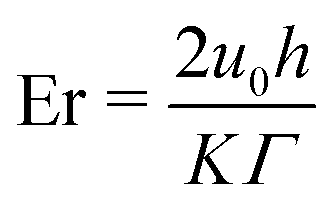
Nematic liquid crystals (NLCs), mesogens comprising rod- or disc-like molecules,15 combine liquid fluidity with crystalline properties, thus offering distinct attributes which arise due to the coupling between the molecular alignment (referred to as the director field n16), hydrodynamics and confinement effects.10,17 LCs form systems with a non-zero orientational order, and the resultant material properties (hydrodynamic, optical, electrical etc.) depend on the mean local director alignment. Controlling the emergent flow behavior via the interplay of elastic, viscous, and surface forces enable unique dynamical properties, offering mechanisms to manipulate LC flows.18–20 Together with geometry of the flow conduits, and the anchoring conditions on the confining surfaces, the bulk director field and the resulting NLC flows fields are established.21–23 The anisotropic viscosity of NLCs has already been exploited in non-intrusive flow control devices,22,24 where the effective viscosity of each channel within a complex microfluidic network is governed by the interplay of surface anchoring and flow speed. Much of potential applications of liquid crystals arise from their anisotropic birefringence: the sensitivity of nematics to external field is essential in tunable lenses,25 color filters,26 optical27,28 and biochemical29 sensors. Furthermore, improving the responsiveness of NLCs to external fields provides pathways to manufacture novel microdisplay and information processing devices.26,30,31 The behavior of the NLC flows in rectangular channels11,32 emerges due to the competition between elastic and viscous effects, captured by the dimensionless Ericksen number, Er;16 microstructure ordering is governed by elastic (viscous) effects in Er ≪ 1 (Er ≫ 1) flows.
Historically, NLC studies were motivated by the development of liquid display devices, where flat channels (width ≫ height) simplified the problem to two dimensions,33–39 however with limited relevance to real microfluidic settings, where the channel height and width are comparable.11,40,41 While these recent efforts have successfully attained tunable LC flows by combining appropriate surface anchoring, confinements, and hydrodynamic forcing, the role of channel curvature has been explored in little detail. Interestingly, curved geometries have been known to impact the behavior of both thermotropic and lyotropic LC systems,42 including the spontaneous emergence of chiral structures from an otherwise achiral phase, for instance in lyotropic chromonic liquid crystals.43,44 Confining the latter material into spherical structures is expected to be a promising avenue for novel flow control methods.45 However, the flow behavior of chromonic phases in curved microfluidic channels, as well, remains to be investigated. In comparison, flows of isotropic fluids through curvilinear microchannels have received extensive attention for many decades, with distinct curvature-induced fluid dynamic outcomes.46–49 In the case of Newtonian fluids, secondary flows in curved pipes are driven by the combination of fluid inertia and geometry curvature.46,49 The secondary flow is strengthened when the fluid is viscoelastic because the positive first normal stress difference, arising from microstructure deformation, has an additive effect with inertia.49,50 Our current understanding of LC flows through complex microfluidic geometries is limited to a few studies, such as those conducted within rectangular channels with obstacles51 and at topological flow junctions.52,53 Initial insight into the physics of microstructure ordering and its effect on the secondary flow in curved geometries was provided by Fedorowicz and Prosser,54,55 who numerically investigated LC flows in capillary bends using the Leslie–Ericksen theory. Their results demonstrate that, similar to viscoelastic fluids, the secondary flow is driven by the interaction of normal stresses with flow curvature. In the case of nematics, normal stresses arise due to the departure of the director from the flow-aligned state54 and can be influenced by surface anchoring.55 However, the behavior of liquid crystals flowing through curved channels has not been explored. We believe that a much richer flow physics can emerge when liquid crystals flow through curved rectangular channels with homeotropic anchoring due to the interaction of conflicting director alignment imposed on the boundaries.11,40 Defects may arise, but these cannot be captured with the vector-based Leslie–Ericksen theory that was used to investigate LC flows in capillary bends.23,56
In this work, we use a combination of LC microfluidic experiments and numerical methods to demonstrate novel flow control mechanisms in curvilinear microfluidic channels of varying complexity (Fig. 1A and B). The quasi-Newtonian behavior observed at low Ericksen number regime Er < 1 is altered as the Ericksen number exceeds Er > 1, along with the emergence of a flow-induced director field gradient in the transverse channel direction. The transverse gradient, introduced by the channel curvature, engenders a flow-partitioning effect due to the backflow mechanism,11 which is amplified by the viscous anisotropy of liquid crystals. Consequently, the throughput through the flow-aligned region scales with the degree of flow-director alignment there. Taken together, the curvature- and Er-mediated modulation of NLC flow properties can be harnessed for potential concepts in LC-based microfluidic flow-guiding elements.
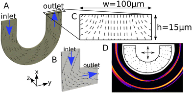 |
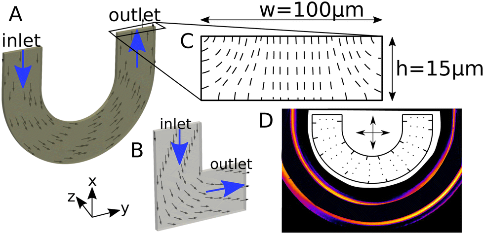
| | Fig. 1 Schematic description of microfluidic channels considered in this paper (A) U-channel; (B) L-channel; (C) static director field at the outlet of the U-channel; (D) light intensity under crossed polarizers and director arrangement in the center plane (inset); dots denote the director alignment perpendicular to crossed polarizers (arrows). The cross-sectional dimensions of L- and U-channels are identical. Numerical simulations assume that the inner radius of the U-bend is ri = 100 μm. The coordinate system in the lower left corner refers to both U and L channels. | |
2. Methods and materials
2.1 Numerical simulations
The flow of an NLC is assumed to be solenoidal and governed by the momentum equation, which reads| | | ρ(∂t + uk∂k)ui = −p,i + μui,jj + τji,j, | (1) |
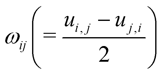
where p,i is the pressure gradient, μ is the Newtonian viscosity and τji is the viscoelastic stress57| | | τij = HikQkj − QikHkj + 2ξ(Qij + δij)HklQklξ[(Qik + δik)Hkj + Hik(Qkj + δkj)] − KQkl,iQkl,j. | (2) |
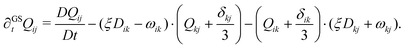
K is the elastic constant and Qij is the order parameter tensor, which evolves according to57| | | ∂GStQij = ΓHij − 2ξ(Qij + δij)Qkluk,l. | (3) |
∂GSt represents the Gordon–Schowalter derivative, which is given by
| |  | (4) |
where
ξ is the slip parameter, and
,
denote the symmetric and antisymmetric components of the velocity gradient.
Γ in
eqn (3) is the rotational diffusivity. The molecular field
Hij is defined in terms of the variational derivative of the Helmholtz free energy
F:
16| |  | (5) |
where
a,
b and
c are material parameters. The relative importance of viscous and elastic effects acting on the microstructure is quantified by the Ericksen number Er =
u0h/(
ΓK), where
u0 is the mean flow speed and
h = 15 μm is the channel height.
We have numerically modeled the Navier–Stokes equations coupled with the Beris-Edwards model in three dimensional U- and L-channels. Numerical solutions were obtained using the OpenFOAM solver rheoFoamLC.58 The solver was it initially based on the director framework of microstructure representation,55 but its extensions allow for incorporating the Q-tensor description;39 the approach is capable of predicting flow-induced defects.39 The system is initialized with an isotropic microstructure and static flow conditions (Q = 0, u = 0). No-slip conditions for the velocity and strong homeotropic anchoring were imposed on all walls. The fluid enters the channel with a uniform velocity at the inlet. The following material constants were used for all simulations; μ = 0.2 Pa s, K = 40 pN, a = −0.2 MJ m−3, b = 4 MJ m−3, c = 4 MJ m−3, ξ = 1, Γ = 7.29 (Pa s)−1. These values are consistent with the material parameters used in similar investigations.11,59 For the selected parameters and geometries, the  is related with the Ericksen number as De = 4.44 × 10⁻⁸, which ensures that De ≪ 1, and thus defect properties were weakly affected by the flow.53
2.2 Experimental measurements
Numerical simulations are complemented with microfluidic experiments, carried out within custom-built U- and L-shaped microchannels having rectangular cross-sections. The microchannels were assembled using polydimethylsiloxane (PDMS) molds and glass plates, bonded together after a brief plasma exposure.60 The assembled channels were first treated with an aqueous solution of the silane DMOAP, that induced homeotropic surface anchoring condition on the inner walls. For the current study, we report experiments with a channel height of 15 μm and width of 100 μm. A single component thermotropic LC (5CB), which is nematic at room temperature, was flowed into the microchannels through cylindrical tubes embedded into holes punched through the PDMS. A precise and controlled LC flow inside the microfluidic channels was achieved by pushing a gas-tight syringe pump using a microfluidic gear pump (with a flow resolution of nl/h). For anchoring characterization, the functionalized channels were filled with 5CB in the isotropic phase, which was first allowed to cool down to a nematic phase. No perceptible swelling of the PDMS by the 5CB was observed during the course of experiments, in agreement with the observed dependence of the swelling ratio on the substance polarity.60,61 We characterize the surface- and bulk director fields using a combination of polarized optical imaging (POM), with and without the λ-retardation plates. The transmitted light depends on the local director alignment relative to the polarizer axes, following ref. 40 and 60.
2.2.1 Materials.
The experiments were carried out using single component thermotropic nematic liquid crystal 4-cyano-4-pentyl-1,1-biphenyl, commonly known as 5CB. 5CB was procured from Synthon Chemicals (Wolfen, Germany), and used without additional purification. Nematic 5CB is appropriate for the liquid crystal flow experiments due to its room temperature nematic phase, with the nematic–isotropic phase transition occuring at ∼33 °C. Additionally, for the duration of the experiments presented here, 5CB is chemically stable within the polydimethylsiloxane (PDMS)-glass microfluidic devices, and has negligible swelling effect on PDMS.60
2.2.2 Microfluidic confinement and flow setup.
The nematic 5CB was flowed through two different curvilinear geometries with rectangular cross-sections: U-shaped and L-shaped microchannels having different dimensions (height, h, and width, w). The microfluidic channels were fabricated out of polydimethylsiloxane (PDMS, Sylgard 184, Dow Corning), a silicon-based organic polymer, on a photoresist master through a process known as soft lithography.60 For the current study, we report experiments with the channel height of 15 μm, and width of 100 μm. The PDMS replicas were bonded to a clean microscope slide by exposing both surfaces to oxygen plasma. The microchannels were functionalized to induce a homeotropic anchoring condition (NLC anchoring perpendicular to the channel surfaces) using appropriate surface anchoring techniques. At both ends of the L-shaped microchannels, cylindrical holes with 750 μm diameter were punched through the PDMS to provide housing for the flow tubing. Teflon tubes typically with 300 μm inner, and 760 μm outer diameters were inserted into each of the housings, and served as connectors for inlet-to-source and outlet-to-sink, respectively. Generation of a precise and controlled LC flow inside the microfluidic channels was achieved by a syringe pump. The channels were connected to a gas-tight microliter syringe (1001LT, Hamilton Bonaduz, Bonaduz, Switzerland), and driven by a gear pump (neMESYS, Cetoni, KorbuÃen, Germany) to create a constant flow volume rate. The average flow speed through the microchannels was verified by tracking tracer particles over time (imaging focused at the channel mid-plane), and the corresponding director field was measured using polarized optical and confocal fluorescence polarized microscopy as described below. The experimental Ericksen number,  , was calculated from the 5CB material properties and the measured experimental flow speed (η denotes the viscosity, v is the flow velocity, L is the characteristic length scale, and K is the single-elastic constant).
2.2.3 Surface anchoring and its characterization.
For inducing homeotropic anchoring condition on the inner walls of the microchannels, the channels were fist filled with a solution of Octadecyldimethyl (3-trimethoxysilyl propyl) ammonium chloride (60% in methanol, ABCR GmbH), commonly known as DMOAP, and left for 10 minutes. The channel was then rinsed with de-ionized water and heated at 80 °C for 15 min and at 110 °C for 1 h. After the thermal treatment, the functionalization was complete. In order to test the surface anchoring condition, the channel was filled with 5CB in isotropic phase and allowed to cool down to nematic phase. No perceptible swelling of PDMS by 5CB was observed during the course of the experiments, in agreement with the observed dependence of the swelling ratio on the substance polarity.60,61 The surface anchoring is characterized by studying the director field in the bulk and close to the channel walls using polarized optical imaging (POM) as described in the next section.
2.2.4 Polarized optical imaging (POM).
The NLC director alignment within the PDMS-glass microfluidic channels was studied using a polarized light microscope (Eclipse LV100N-POL, Nikon), equipped with different objectives ×5, ×10, ×20, and ×40 objectives. The sample was maintained at room temperature. Various experimental cases were captured using the following orientations of the crossed-polarizers using transmitted white light: (a) the microfluidic channel arm parallel to one of the crossed-polarizers, (b) the channels oriented at 45° with respect to the polarizers, and (c) with and without the insertion of a 530 nm phase-retardation plate. POM images were acquired using a digital Canon EOS77D camera. The acquired POM data were quantified using a combination of ImageJ and MATLAB softwares, to finally extract the intensity plots (Fig. 5 in appendix B) due to the flow-induced director fields.10,11
3. Results
3.1 Analytical prediction
Assuming that the liquid crystal is uniaxial and the order parameter is constant, the Beris–Edwards model (with ξ = 1) can be simplified to the Leslie–Ericksen theory and the steady-state angular momentum balance equation reduces to a non-linear Poisson equation| | (∂yy + ∂zz)θ + ux,zEr![[thin space (1/6-em)]](https://www.rsc.org/images/entities/char_2009.gif) sin2θ = 0, sin2θ = 0, | (6) |
where θ is the angle between the director and the flow direction (eqn (6) is derived in Appendix A). When Er ≪ 1, wall imposed homeotropic anchoring forces the director to align in the y–z plane, normal to the flow direction. When Er = O(1) viscous effects become significant, manifesting through the rotation of the director field towards the Leslie angle, which is aligned with the flow direction in the limit of uniaxial ordering with ξ = 1. Eqn (6) suggests that the local velocity gradient amplifies the effect of Ericksen number: flow alignment is promoted in regions of elevated shear rate.
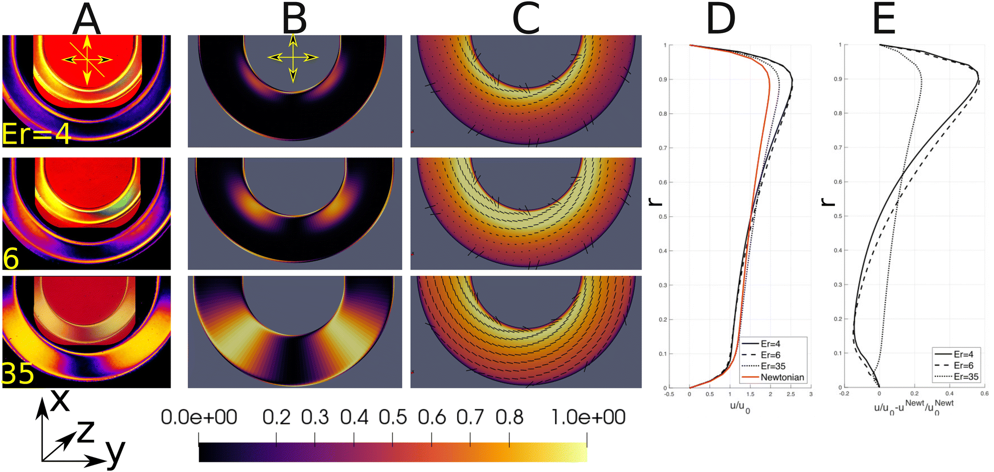
3.2 U-bend
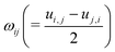
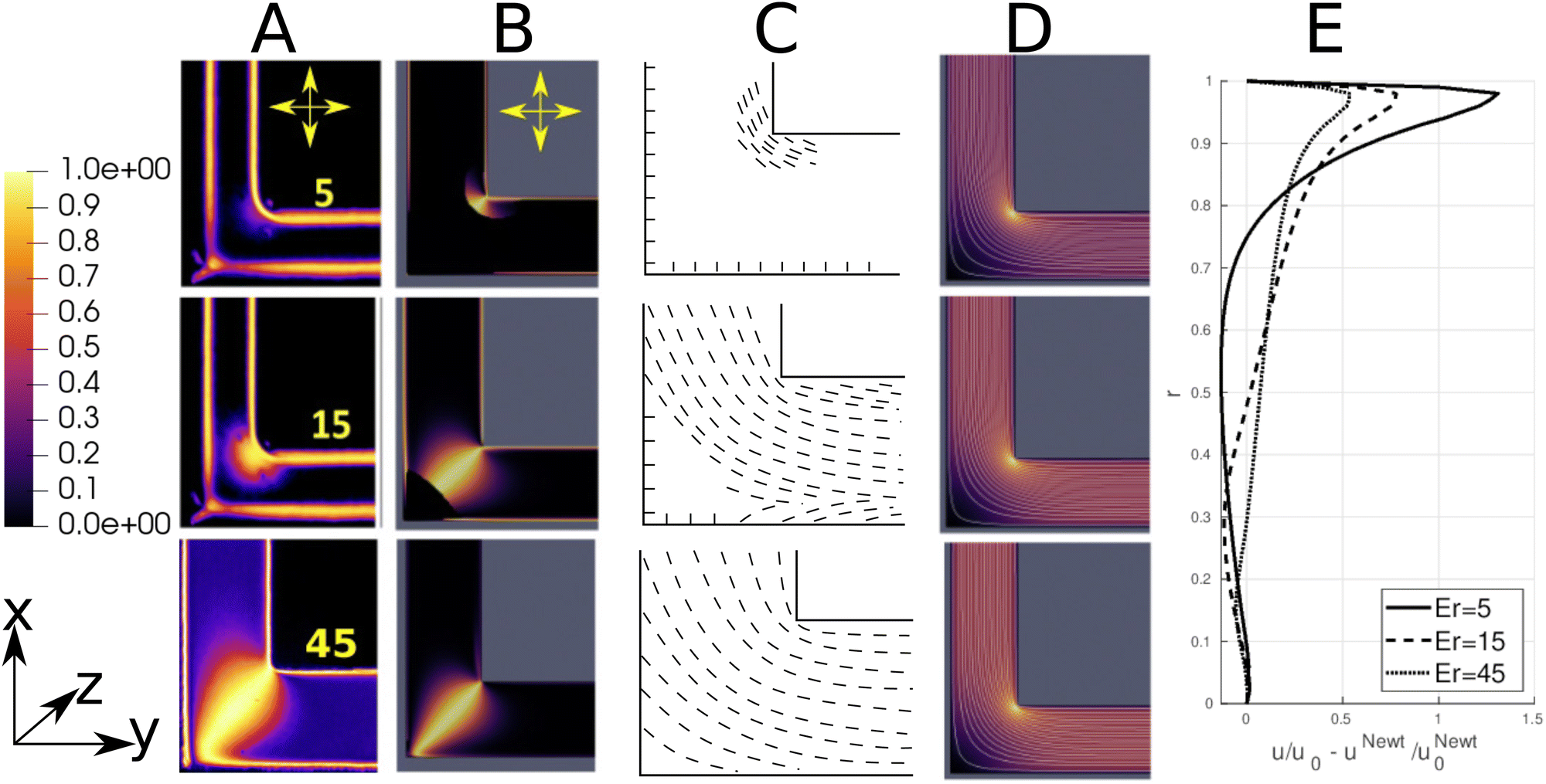
The analytical result has been qualitatively confirmed by experimental measurements and numerical calculations. The director aligns in the z-direction at Er ≪ 1, as indicated by the uniform dark signal throughout the U-bend (Fig. 1D). At Er = O(1) the director alignment is also affected by viscous effects. In creeping flows, the peak velocity is displaced towards the bend axis54,55 and the resulting elevated shear rate is responsible for the emergence of the flow-aligned director field at the inside of the bend at Er = 4. The result is experimentally observed through a non-zero light intensity signal near the inner wall (upper row in Fig. 2A), and is qualitatively confirmed by numerical simulations (Fig. 2B and C). The size of the flow-aligned region scales with the Ericksen number. For Er = 6, the elasticity dominated region of the director field is confined to the outer bend wall (middle row in Fig. 2), where there is consequently relatively little flow. Further evidence for the shear-induced propagation of the flow-aligned region towards the outside of the bend is provided in Fig. 5.
 |
| | Fig. 2 Director alignment in a flow through U-bend. (A) Experimental micrographs showing transmitted light intensity under crossed polarizers. Inset: polarized micrograph with a λ-retardation plate; the yellow and the blue-green signals respectively denote director alignment parallel and perpendicular to the retardation plate. (B) Numerical prediction of intensity under crossed polarizers (calculated as 4nx2ny2) in the symmetry plane. (C) Density plots of velocity magnitude scaled by the maximum flow speed and glyphs of the director field (symmetry plane). (D) Velocity profile in the center of the bend. (E) Amplification of flow asymmetry induced by the anisotropic microstructure. r denotes the normalized distance from the outer to the inner bend wall, u is the flow speed in the centerplane, superscript N and subscript 0 refer to the Newtonian fluid and the mean flow speed, respectively. | |
The combination of nematic viscoelasticity and geometric curvature produces variable director alignment across the channel. More flow is promoted in regions where flow alignment is achieved. Fig. 2D and E show that the presence of nematic liquid crystals amplifies the uneven flow distribution introduced by the geometry. Novel mechanisms for flow partitioning controlled by the Ericksen number may thus be identified. The potential for flow tuning is weaker at high Ericksen numbers, where the dominance of viscous effects results in complete flow alignment (lower row in Fig. 2) and thus nearly uniform effective viscosity. The corresponding velocity profile (dotted line in Fig. 2D) is much more similar to the Newtonian result than at intermediate Er. Additional simulations (not reported here) show that as the Ericksen number increases, viscous effects dominate the director alignment and stress distribution, resulting in the Newtonian velocity profile (u/u0 − uN/uN0 = 0).11
3.3 L-channel
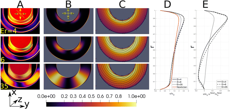
The physics governing microstructure arrangement in an L-channel is qualitatively similar to the U-bend. Here, the change in flow direction occurs over a smaller length scale, so flow-aligning effects are more localized near the inner corner. The effect can be seen experimentally in Fig. 3A and numerically in Fig. 3B and C. Both experiments and simulations show that higher flow speeds in the L-channel occur near the inner corner. The crossed polarizer images indicate that director alignment is initiated there. Similar to the U-bend flow, the curvature in the L-channel introduces a positive feedback mechanism: reduced effective viscosity in the flow-aligned inner corner promotes further flow there (indicated by tighter streamline concentrations in Fig. 3D). At Er = 15, the director remains unaligned with the flow only in the outer corner of the elbow, which results in a stagnation region there. The L-bend is thus seen to act like a microfluidic valve, where the effective valve throat is controlled by the Ericksen number. The valve effect becomes stronger as the radius of curvature decreases; at the inner corner of the L-bend the relative increase in velocity is up to three times larger than near the inner wall of the U-bend (Fig. 3E). The effect of flow asymmetry is reduced at high Er, where flow dynamics dominate director alignment and the overall rheology tends toward a Newtonian fluid (Fig. 3E).
 |
| | Fig. 3 Director alignment in a flow through the L-channel. (A) Intensity image obtained with crossed polarizers. (B) Numerical prediction of intensity with crossed polarizers (calculated as 4nx2ny2). (C) Glyphs of the director field. (D) Contours of flow magnitude scaled by the maximum flow speed. The Ericksen number is denoted by the white number in the lower left corner of column A pictures. (E) Effect of nematic liquid crystals on the amplification of flow asymmetry (in the symmetry of the U-bend) with respect to a Newtonian fluid. r denotes the normalized distance from the outer to the inner corner, u is the flow speed in the centerplane, superscript N and subscript 0 refer to the Newtonian fluid and the mean flow speed, respectively. | |
3.3.1 Flow tuning through defect-promoted shear banding.
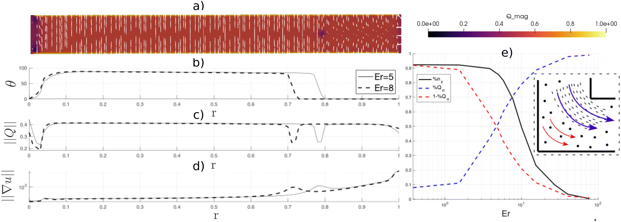
Numerical simulations show that the separation between the flow- and z-aligned director field induces defects (dark dot on the right side of Fig. 4a) in the microstructure. Increasing Er moves the defect towards the outer wall, which manifests through the displacement of the director transition region (Fig. 4b) and the accompanying lower order parameter region (Fig. 4c). The presence of a defect affects the velocity gradient (Fig. 4d) and produces a novel type of shear banding. The location of the defect marks the onset of the flow-aligned director field and thus the defect separates lower shear rate and higher shear rate regions. This provides a novel type of flow transition; previous studies of shear banding in liquid crystals are driven by the nematic–isotropic transition arising from flow62 or temperature11 effects.
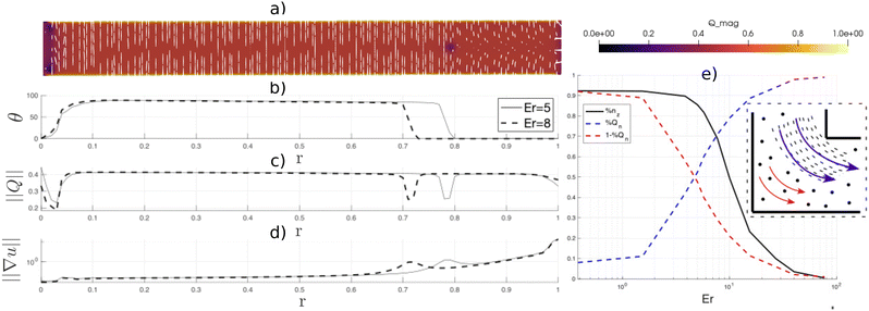 |
| | Fig. 4 (a) Order parameter and director field (white rods) between the outer and inner corner at Er = 5; (b) variation of the director angle between L-bend corners; (c) variation of the order parameter between L-bend corners; (d) velocity gradient between L-bend corners; (e) channeling NLC flows through curved channels over a range of Ericksen numbers. %nz is the fraction of the corner region occupied by the z-aligned director field, and %Qn represents the flow fraction (blue arrows in the inset) through the region where the n (black dashed lines in the inset) aligns with the flow. Red arrows in the inset represent the velocity vectors in the region where n aligns in the flow transverse direction (denoted by black dots). | |
Flow control across a range of Ericksen numbers can be achieved by managing the size of the stagnation region. Fig. 4e shows that as the size of the flow-transverse director region decreases (solid black line), the throughput through the flow-aligned region local to the inner corner increases (blue dashed line). Thus, flow channelization is induced by the anisotropic director field, and the throughput near the inner corner (r > 0.9) can be up to 50% larger for nematic flows than for Newtonian fluids under identical channel curvature conditions.
4. Conclusions
Nematic liquid crystals flowing through curvilinear microchannels produce a transverse gradient of the director field, which can feedback into the flow field and produce curvature-director-flow coupling. For ranges of Ericksen number, this coupling can create abrupt flow changes, thereby inducing topological defects and generating binary flow states. Flow alignment of the director field initiates at Er ≈ 2 and is promoted (hindered) in locations of higher (lower) flow speeds. The effect becomes stronger as the geometric curvature increases, and produces a positive feedback effect: as the director alignment increases, the apparent viscosity reduces, along with the reduction of boundary layer size. This has a channeling effect on the velocity distribution, and more flow is promoted in the flow-aligned region. Decreasing geometry curvature increases the degree of flow asymmetry; consequently, higher Ericksen numbers are required to promote the complete flow alignment. These findings could guide the development of potential applications, for instance, featureless flow-guidance circuits, LC-based microfluidic logic gates and optofluidic switches.
Liquid crystals offer a promising avenue for advancing microfluidic flow control devices. However, their applicability is subject to potential limitations. Scaling problems may arise in larger geometries, where Er ≫ 1 produces Newtonian behavior, as discussed in Section 3.2. Additionally, liquid crystals are prone to forming defect structures, the occurrence of which requires careful handling of the microfluidic device. Finally, the utility of microfluidic devices is constrained by the temperature sensitivity of liquid crystals because anisotropic properties are lost below the nematic–isotropic transition temperature. Curvilinear microfluidic experiments with lyotropic chromonic phases could offer tangible avenues to offset the temperature sensitivity of thermotropic phases, specifically by tuning the concentration of the lyotropic chromonic surfactants.63,64 Owing to the role of chromonic phases in diverse applications, studies on their flow through curvilinear geometries could be relevant for manipulation of different drugs, dye molecules and nucleic acids.
In future work, we aim to investigate microfluidic geometries where extensional flow plays a role in the liquid crystal alignment; examples include expansions, T and Y junctions. Additional investigations are also underway to assess the potential of using electric fields in flow manipulation.
Data availability
All data are available from the corresponding author on reasonable request.
Author contributions
R. P. and K. F. conducted numerical simulations, A. S. carried out experiments. All authors contributed equally to formal analysis and writing.
Conflicts of interest
There are no conflicts to declare.
Appendices
A Analytical quantification of the flow effect on the director field
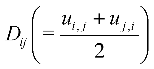
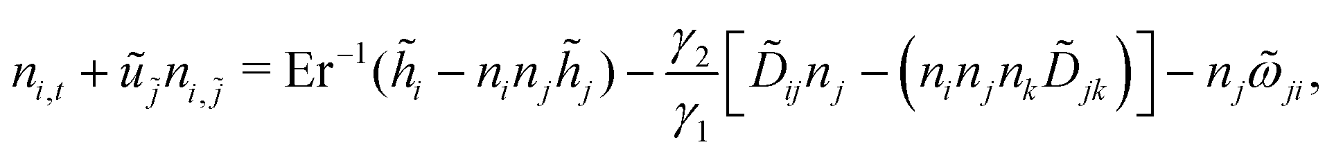
The angular momentum balance of the Beris–Edwards model in the uniaxial, constant order parameter limit reduces to the Leslie–Ericksen theory.33,56,65| | | γ1(ni,t + ujni,j) = hi − ninjhj − γ2[Dijnj − (ninjnkDjk)] − γ1njωji, | (7) |
where hi = Kni,jj is the molecular field. The coefficients γ1 and γ2 can be expressed in terms of the Beris–Edwards material parameters19| |  | (8) |
Introducing the dimensionless parameters| |  | (9) |
the director evolution equation can be written as| |  | (10) |
where  . The general problem may be simplified by making the following assumptions:
• The system is in the steady state.
• The system is fully developed.
• The order parameter is constant Q = 1.
• We have chosen ξ = 1, so from eqn (8) we have  .
.
With the assumptions above, the angular momentum eqn (10) reduces to
| |  | (11) |
where the underlined terms ensure that the director retains unit magnitude. The
x-component of the director balance equation reads
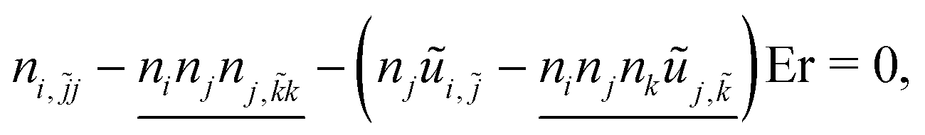
| | nx,ỹy + nx,![[z with combining tilde]](https://www.rsc.org/images/entities/i_char_007a_0303.gif) z − [nyũx,ỹ + nzũx,](1 − nx2)Er − nx[nx(nx,ỹy + nx,z) + ny(ny,ỹy + ny,z) + nz(nz,ỹy + nz,z)] = 0. z − [nyũx,ỹ + nzũx,](1 − nx2)Er − nx[nx(nx,ỹy + nx,z) + ny(ny,ỹy + ny,z) + nz(nz,ỹy + nz,z)] = 0. | (12) |
Assuming that the director remains in the
x–
z plane (with the flow taking place in the
x-direction and the velocity gradient in the
z-direction), we can express its components in terms of the polar angle
θ that it makes with the flow direction (
n = [
nx,
ny,
nz] = [cos
θ, 0, sin
θ]), and the director balance simplifies to
| | (∂ỹy + ∂z)θ + ũ![[x with combining tilde]](https://www.rsc.org/images/entities/i_char_0078_0303.gif) ,Ersin2θ = 0. ,Ersin2θ = 0. | (13) |
B. Light intensity in the U- and L-channels
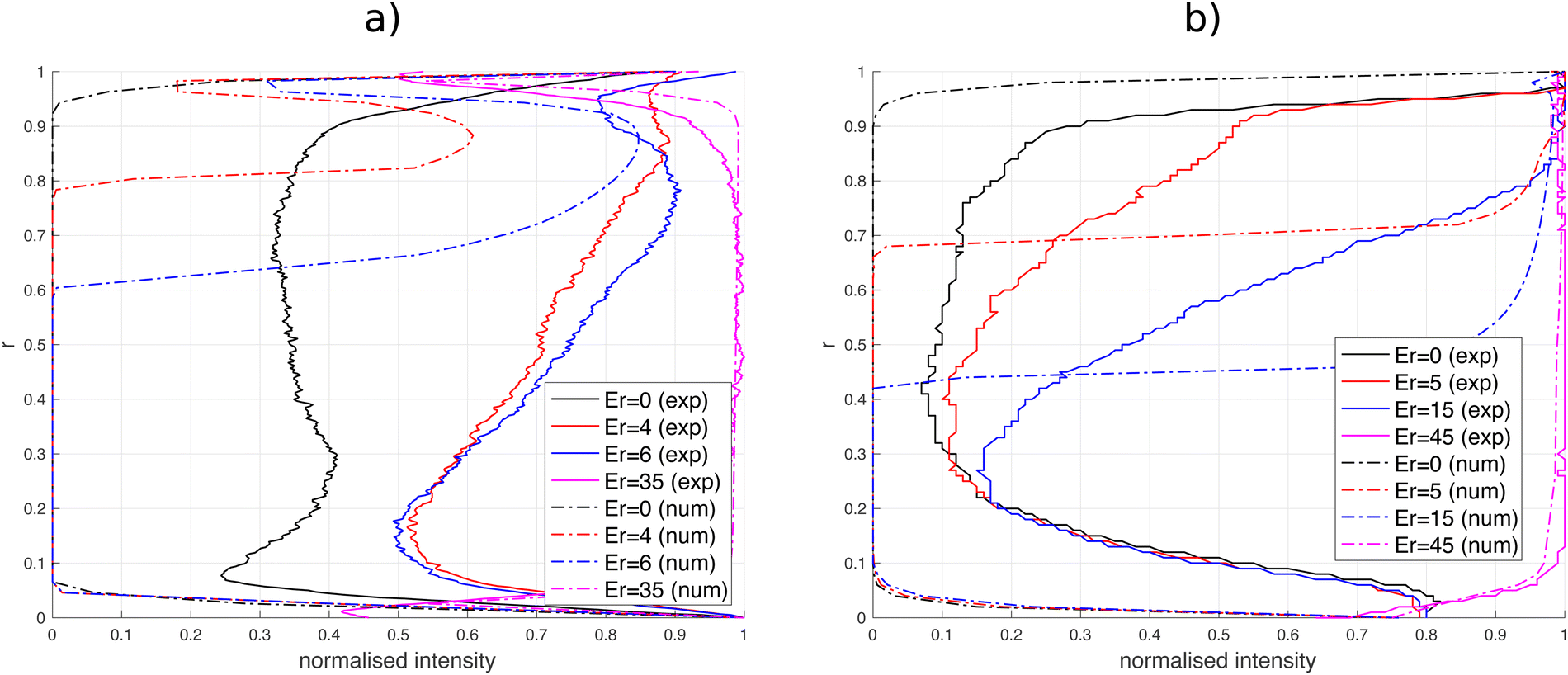
Fig. 5 compares the experimental and numerical intensity profiles across the U- and L-bends. Experimental measurements are z-integrated over the channel depth, while the intensity in numerical simulations is taken at the centerplane. Both approaches indicate a higher light intensity at the inner inner wall/corner (r > 0.5) in the U-bend/L-channel that is caused by the improved flow/director alignment there (Fig. 5a and b). The sharp transition predicted by the numerical simulations is a manifestation of the defect boundary, as discussed in Section 3.3.1.
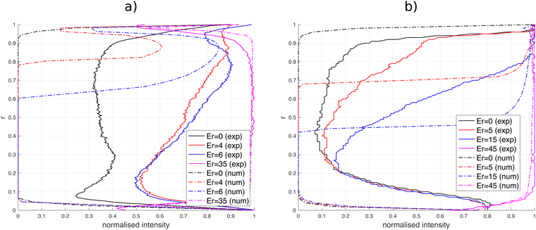 |
| | Fig. 5 Normalized light intensity (a) at a 135° angle from the U-bend entrance; (b) between the inner and outer corner of the L-bend. r denotes the normalized distance from the outer U-bend wall and from then inner corner in the L-bend, respectively. | |
Acknowledgements
KF and RP acknowledge the EPSRC project the Centre in Advanced Fluid Engineering for Digital Manufacturing (grant no. EP/R00482X/1) and Unilever plc for financial support. KF and RP would like to acknowledge the assistance given by Research IT and the use of the Computational Shared Facility at The University of Manchester. AS thanks the Luxembourg National Research Fund's ATTRACT Investigator Grant (grant no. A17/MS/11572821/MBRACE) and CORE Grant (C19/MS/13719464/TOPOFLUME/Sengupta) for supporting this work.
Notes and references
-
H. Bruus, Theoretical Microfluidics, Oxford University Press, Oxford (UK), 2008 Search PubMed.
- G. M. Whitesides, Nature, 2006, 442, 368–373 CrossRef CAS PubMed.
- T. Pfohl, F. Mugele, R. Seemann and S. Herminghaus, Chem. Phys. Chem., 2003, 4, 1291–1298 CrossRef CAS PubMed.
- G. Kunti, J. Dhar, A. Bhattacharya and S. Chakraborty, Phys. Fluids, 2019, 9, 092003 CrossRef.
- F. Paratore, V. Bacheva, M. Bercovici and G. V. Kaigala, Nat. Rev. Chem., 2021, 6, 70–80 CrossRef PubMed.
- O. J. Dressler, R. M. Maceiczyk, S.-I. Chang and A. J. deMello, SLAS Discovery, 2014, 19, 483–496 CrossRef PubMed.
- K. W. Oh, Micromachines, 2020, 11, 370 CrossRef PubMed.
- D. J. Beebe, G. A. Mensing and G. M. Walker, Annu. Rev. Biomed. Eng., 2002, 4, 261–286 CrossRef CAS PubMed.
- J. Priyadarshani, T. Roy, S. Das and S. Chakraborty, ACS Biomater. Sci. Eng., 2021, 7, 483–496 Search PubMed.
- A. Sengupta, S. Herminghaus and C. Bahr, Liq. Cryst. Rev., 2014, 2, 73–110 CrossRef CAS.
- A. Sengupta, U. Tkalec, M. Ravnik, J. M. Yeomans, C. Bahr and S. Herminghaus, Phys. Rev. Lett., 2013, 110, 048303 CrossRef PubMed.
- A. Sengupta, C. Bahr and S. Herminghaus, Soft Matter, 2013, 9, 7251–7260 RSC.
- M. Ravnik and J. M. Yeomans, Phys. Rev. Lett., 2013, 110, 026001 CrossRef PubMed.
- Z. Kos and M. Ravnik, Sci. Rep., 2020, 10, 1446 CrossRef CAS PubMed.
-
I. Stewart, The Static and Dynamic Continuum Theory of Liquid Crystals: A Mathematical Introduction, Taylor and Francis, London, 2004 Search PubMed.
-
P. de Gennes and J. Prost, The Physics of Liquid Crystals, Oxford Science Publications, 1993 Search PubMed.
- Y. Xu, A. M. Rather, Y. Yao, J.-C. Fang, R. S. Mamtani, R. K. A. Bennett, R. G. Atta, S. Adera, U. Tkalec and X. Wang, Sci. Adv., 2021, 7, eabi7607 CrossRef CAS PubMed.
- Z. Khoshbin, K. Abnous, S. M. Taghdisi and A. Verdian, Trends Anal. Chem., 2021, 142, 116325 CrossRef CAS.
- S. J. Woltman, G. D. Jay and G. P. Crawford, Nat. Mater., 2007, 6, 116325 CrossRef PubMed.
- K. Fedorowicz and R. Prosser, Liq. Cryst., 2023, 1–24 CrossRef.
- P. Pieranski and E. Guyon, Phys. Lett. A, 1974, 49, 237–238 CrossRef.
- A. Sengupta, Int. J. Mol. Sci., 2013, 14, 22826–22844 CrossRef PubMed.
- P. Steffen, E. Stellamanns and A. Sengupta, Phys. Fluids, 2021, 33, 072005 CrossRef CAS.
- Y.-J. Na, T.-Y. Yoon, S. Park, B. Lee and S.-D. Lee, Chem. Phys. Chem., 2010, 11, 101–104 CrossRef CAS PubMed.
- D. Wee, S. H. Hwang, Y. S. Song and J. R. Youn, Soft Matter, 2016, 12, 3868–3876 RSC.
- J. G. Cuennet, A. E. Vasdekis and D. Psaltis, Lab Chip, 2013, 13, 2721–2726 RSC.
- A. Sengupta, S. Herminghaus and C. Bahr, Appl. Phys. Lett., 2012, 101, 164101 CrossRef.
- J.-C. Eichler, R. A. Skutnik, A. Sengupta, M. G. Mazza and M. Schoen, Mol. Phys., 2019, 117, 3715–3733 CrossRef CAS.
- Y. Liu, D. Cheng, I.-H. Lin, N. L. Abbott and H. Jiang, Lab Chip, 2012, 12, 3746–3753 RSC.
- D. Vettese, Nat. Photonics, 2010, 4, 752–754 CrossRef CAS.
- J. G. Cuennet, A. E. Vasdekis, L. De Sio and D. Psaltis, Nat. Photonics, 2011, 5, 234–238 CrossRef CAS.
- S. Čopar, Z. Kos, T. Emeršič and U. Tkalec, Nat. Commun., 2020, 11, 59 CrossRef PubMed.
- C. Denniston, E. Orlandini and J. M. Yeomans, Phys. Rev. E, 2001, 63, 056702 CrossRef CAS PubMed.
- C. Denniston, E. Orlandini and J. Yeomans, Comput. Theor. Polym. Sci., 2001, 11, 389–395 CrossRef CAS.
-
M. Kleman and O. D. Lavrentovich, Soft Matter Physics: An Introduction, Springer New York, 2003 Search PubMed.
- J. Quintans-Carou, B. R. Duffy, N. J. Mottram and S. K. Wilson, Phys. Fluids, 2006, 18, 027105 CrossRef.
- P. A. Cruz, M. F. Tome, I. W. Stewart and S. McKee, J. Comput. Phys., 2013, 247, 109–136 CrossRef CAS.
- A. D. Rey and M. M. Denn, Annu. Rev. Fluid Mech., 2002, 34, 233–266 CrossRef.
- K. Fedorowicz and R. Prosser, J. Non-Newton. Fluid Mech., 2022, 310, 104949 CrossRef CAS.
-
A. Sengupta, Topological microfluidics - nematic liquid crystals and nematic colloids in microfluidic environment, Springer, 2013 Search PubMed.
- S. Mondal, I. M. Griffiths, F. Charlet and A. Majumdar, Fluids, 2018, 3, 39 CrossRef.
-
M. Srinivasarao, Spontaneous Emergence of Chirality, John Wiley & Sons, Ltd, 2021, ch. 5, pp. 311–346 Search PubMed.
- K. Nayani, R. Chang, J. Fu, P. W. Ellis, A. Fernandez-Nieves, J. O. Park and M. Srinivasarao, Nat. Commun., 2015, 6, 8067 CrossRef CAS PubMed.
- J. Fu, K. Nayani, J. O. Park and M. Srinivasarao, NPG Asia Mater., 2017, 9, e393 CrossRef CAS.
- C. M. Tone, A. Zizzari, L. Spina, M. Bianco, M. P. De Santo, V. Arima, R. C. Barberi and F. Ciuchi, Langmuir, 2023, 39, 6134–6141 CrossRef CAS PubMed.
- W. R. Dean, Proc. R. Soc. Lond. A, 1928, 121402–121420 Search PubMed.
- D. Di Carlo, Lab Chip, 2009, 9, 3038–3046 RSC.
- V. Steinberg, Annu. Rev. Fluid Mech., 2021, 53, 27–58 CrossRef.
- Y. Fan, R. I. Tanner and N. Phan-Thien, J. Fluid Mech., 2001, 440, 327–357 CrossRef CAS.
- A. Robertson and S. Muller, Int. J. Non-Linear Mech., 1996, 31, 1–20 CrossRef.
- A. Sengupta, C. Pieper, J. Enderlein, C. Bahr and S. Herminghaus, Soft Matter, 2013, 9, 1937–1946 RSC.
- L. Giomi, Z. Kos, M. Ravnik and A. Sengupta, Proc. Natl. Acad. Sci. U. S. A., 2017, 114, E5771–E5777 CrossRef CAS PubMed.
- Z. Kos, M. Ravnik and S. Zumer, Liq. Cryst., 2017, 44, 2161–2171 CAS.
- K. Fedorowicz and R. Prosser, J. Non-Newton. Fluid Mech, 2022, 300, 104716 CrossRef CAS.
- K. Fedorowicz and R. Prosser, Phys. Fluids, 2022, 34, 063106 CrossRef CAS.
- F. M. Leslie, Q. J. Mech. Appl. Math., 1966, 19, 357–370 CrossRef CAS.
-
A. Beris and B. Edwards, Thermodynamics of Flowing Systems with an Internal Microstructure, Oxford University Press, 1994 Search PubMed.
-
K. Fedorowicz, Source code of the rheoFoamLC solver and the implementation of constitutive equations, 2022, https://github.com/KamilFedorowicz.
- M. Ravnik and S. Zumer, Liq. Cryst., 2009, 36, 1201–1214 CrossRef CAS.
- A. Sengupta, B. Schulz, E. Ouskova and C. Bahr, Microfluid. Nanofluid., 2012, 13, 941–955 CrossRef CAS.
- A. Sengupta, Liq. Cryst., 2014, 41, 290–301 CrossRef CAS.
- J. K. G. Dhont, M. P. Lettinga, Z. Dogic, T. A. J. Lenstra, H. Wang, S. Rathgeber, P. Carletto, L. Willner, H. Frielinghaus and P. Lindner, Faraday Discuss., 2003, 123, 157–172 RSC.
- A. Sharma, I. L. H. Ong and A. Sengupta, Crystals, 2021, 11, 35 CrossRef CAS.
- V. Ulaganathan and A. Sengupta, J. Colloid Interface Sci., 2023, 649, 302–312 CrossRef CAS PubMed.
- O. Parodi, J. Phys., 1970, 31, 581–584 CrossRef CAS.
|
| This journal is © The Royal Society of Chemistry 2023 |

 Open Access Article
 This Open Access Article is licensed under a
  *a,
Robert
Prosser
a and
Anupam
Sengupta
*a,
Robert
Prosser
a and
Anupam
Sengupta

 ,
,  denote the symmetric and antisymmetric components of the velocity gradient. Γ in eqn (3) is the rotational diffusivity. The molecular field Hij is defined in terms of the variational derivative of the Helmholtz free energy F:16
 is related with the Ericksen number as De = 4.44 × 10⁻⁸, which ensures that De ≪ 1, and thus defect properties were weakly affected by the flow.53
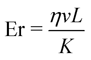 , was calculated from the 5CB material properties and the measured experimental flow speed (η denotes the viscosity, v is the flow velocity, L is the characteristic length scale, and K is the single-elastic constant).


 . The general problem may be simplified by making the following assumptions:
 .
.