Interactions between polymers and liquids during initiated chemical vapor deposition onto liquid substrates
Mark M.
De Luna
 ,
Prathamesh
Karandikar
and
Malancha
Gupta
 *
*
Mork Family Department of Chemical Engineering and Materials Science, University of Southern California, Los Angeles, California 90089, USA. E-mail: malanchg@usc.edu
First published on 23rd September 2019
Abstract
Vapor phase deposition is typically used to apply thin films and coatings onto solid substrates. Deposition of materials onto liquid substrates provides complexity due to surface tension, viscosity, and solubility effects. Understanding the interactions between the deposited material and the liquid substrate can lead to the formation of materials with new structures and compositions. In this review, we will discuss the interactions associated with initiated chemical vapor deposition of polymers onto liquid substrates including silicone oils and ionic liquids. We will provide guidelines for selecting liquid properties to control the formation of polymer particles, films, and gels. We will conclude by discussing recent work on combining polymer and metal deposition to create hybrid organic/inorganic structures and actively moving the liquid during polymer deposition.
Design, System, ApplicationThis review article highlights the interactions between the polymer and the liquid substrate during initiated chemical vapor deposition. Different polymer morphologies of varying length scales can be obtained including nanoparticles, films, and gels by selecting the surface tension of the polymer and liquid, the viscosity of the liquid, and the solubility of the monomer. The polymer deposition time can be varied to control the size of the particles and the thickness of the films. Ionic liquids can be incorporated into gels or encapsulated within polymer shells. We also highlight recent work that demonstrates that sputter deposition can combined with initiated chemical vapor deposition to fabricate hybrid organic/inorganic materials for potential applications in electronics and catalysis. |
Introduction
The initiated chemical vapor deposition (iCVD) process is a solventless technique that can be used to deposit functional polymer coatings onto a variety of solid substrates.1–3 In the iCVD process, monomer and initiator vapors are delivered continuously into a reactor that is kept at 50–500 mTorr. A heat exchanger is used to cool the substrate to a desired temperature typically between 20–40 °C. The initiator molecules are thermally cleaved into free radicals by a nichrome filament array heated to 200–250 °C, and these free radicals diffuse to the substrate. The concentration of monomer that adsorbs to the substrate can be increased by decreasing the substrate temperature,4 increasing the monomer flow rate,4,5 or increasing the reactor pressure.4–6 Polymerization occurs via a classical free radical mechanism leading to average molecular weights ranging from 10![[thin space (1/6-em)]](https://www.rsc.org/images/entities/char_2009.gif) 000 to 800
000 to 800![[thin space (1/6-em)]](https://www.rsc.org/images/entities/char_2009.gif) 000 Da with typical PDIs of 1.7–2.6.7–9 The solventless nature of the iCVD process allows for deposition of conformal polymer coatings onto substrates with complex geometries including microtrenches,10–12 fibers,13–15 membranes,16–18 carbon nanotubes,19,20 and microfluidic channels.21,22
000 Da with typical PDIs of 1.7–2.6.7–9 The solventless nature of the iCVD process allows for deposition of conformal polymer coatings onto substrates with complex geometries including microtrenches,10–12 fibers,13–15 membranes,16–18 carbon nanotubes,19,20 and microfluidic channels.21,22
The introduction of liquids as substrates during vapor phase deposition processes is complex due to a wide variety of possible interactions between the deposited material and the liquid. The liquid substrates must have low vapor pressures to prevent evaporation. A wide variety of liquids satisfy this criterion including ionic liquids, silicone oils, glycerol, squalene, and Krytox. Ionic liquids (ILs) are of particular interest because of their high ionic conductivity, thermal stability, and wide electrochemical window which allows for applications in energy storage, chemical synthesis, and gas absorption.23–25 Silicone oils are an ideal substrate since they are nontoxic, have a range of viscosities, and are inert, which allows for studying the effects of liquid properties in the absence of chemical interactions. The vapor phase deposition of inorganic materials onto liquid substrates via thermal evaporation and sputter deposition has been recently studied.26–38 It was found that sputtering conditions,39,40 liquid properties,29,30 and the type of sputtered metal32 can be varied to create structures such as ramified aggregates, nanoparticles, and films. These types of nanostructured materials have potential uses in catalysis and plasmonics.41 The curved surface of liquid substrates is useful for fabricating mirrors and lenses. For example, chromium was deposited onto IL to fabricate a mirror for a lunar telescope.32 The vapor phase deposition of organic materials onto liquid substrates has been studied less than inorganic deposition. The deposition of parylene has been used for the encapsulation of liquids for use as intraocular lenses.42–44 For example, a liquid lens with a tunable focal distance was fabricated by depositing parylene onto a droplet of silicone oil.44
Our group demonstrated for the first time that iCVD can be used to deposit polymers onto liquid substrates in 2011.45 This review paper will focus specifically on the interactions between the polymer and the liquid substrate during iCVD. We will highlight the different polymer morphologies of varying length scales that can be obtained by selecting the surface tension of the polymer and liquid, the viscosity of the liquid, and the solubility of the monomer. We will demonstrate the high throughput synthesis of polymer nanoparticles which can be useful for fabricating materials for drug delivery46 and catalysis.47 We will demonstrate that ionic liquids can be encapsulated within polymer shells or incorporated into gels. We will also show that sputter deposition can combined with initiated chemical vapor deposition to fabricate hybrid organic/inorganic materials which are potentially useful for applications in electronics,48 drug delivery,49 separations,50 catalysis,51 and environmental remediation.52 Our review specifically focuses on iCVD deposition onto liquid substrates because the versatility of the process allows for systematic variation of different parameters. For example, the solubility of the system can be varied by choosing different combinations of monomers and liquids and the surface energy of the deposited polymer can be varied from 20 to 60 mN m−1 which is not achievable for high surface energy materials such as metals.30 The iCVD process also allows for systematic variation of the molecular weight of the polymer chains and the degree of crosslinking which allows the effects of diffusion and aggregation to be systematically studied. Although this review focuses on iCVD deposition onto liquids, the fundamental insight provided in this review can be applied to other deposition methods as we have recently shown in our sputtering studies.30,53
For our first demonstration of iCVD onto liquids, we studied the deposition of poly(1H,1H,2H,2H-perfluorodecyl acrylate) (PPFDA) and poly(2-hydroxyethyl methacrylate) (PHEMA) onto a droplet of 1-butyl-3-methylimidazolium hexafluorophosphate ([bmim][PF6]).45 We found that polymerization could either occur at the vapor–liquid interface or within the bulk of the liquid depending on the solubility of the monomer within the liquid. The solubility of the monomers in the liquids can be tested using an in situ quartz crystal microbalance (QCM). The monomer, 1H,1H,2H,2H-perfluorodecyl acrylate (PFDA), is not soluble in [bmim][PF6] and therefore polymerization occurs only at the vapor–liquid interface whereas the monomer, 2-hydroxyethyl methacrylate (HEMA), is soluble within [bmim][PF6] and therefore polymerization occurs at both the vapor–liquid interface and within the bulk liquid. In this review paper, we will discuss the different structures that can be formed for insoluble45,54–59 and soluble systems8,45,54,60,61 as shown in Fig. 1. For the case of insoluble monomers, the structures formed at the vapor–liquid interface are composed only of polymer whereas for the case of soluble systems, the liquid is incorporated into the final structure.
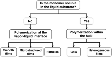 | ||
| Fig. 1 Flow diagram of different structures that can be formed for cases where the monomer is either insoluble or soluble within the liquid substrate. | ||
For the cases where the monomer is insoluble in the liquid, the surface tension interaction between the polymer and the liquid is the key parameter that determines the morphology of the deposited polymer at the vapor–liquid interface. We investigated the effect of surface tension by studying the deposition of six different polymers of varying surface tensions onto seven different liquids. Our data showed that the spreading coefficient (S) dictates the final polymer morphology at the vapor–liquid interface.54 The spreading coefficient of low surface energy materials is defined as:
S = γLV × (1 + cos![[thin space (1/6-em)]](https://www.rsc.org/images/entities/char_2009.gif) θA) − 2γPV θA) − 2γPV |
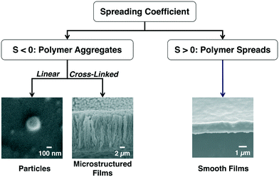 | ||
| Fig. 2 The spreading coefficient determines whether polymer aggregation or polymer spreading is more energetically favorable. | ||
Polymer particles
If the monomer is insoluble in the liquid and the spreading coefficient is negative, the polymer chains will aggregate to form particles.54,57–59,64 These polymer particles can either remain at the vapor–liquid interface or submerge into the bulk liquid which is determined by the Gibbs free energy of particle detachment from the vapor–liquid interface (ΔG):ΔG = −πr2γLV(1 − cos![[thin space (1/6-em)]](https://www.rsc.org/images/entities/char_2009.gif) θ)2 θ)2 |
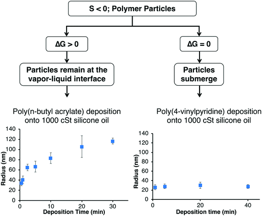 | ||
| Fig. 3 Particles can either remain at the vapor–liquid interface or submerge within the bulk which depends on the Gibbs free-energy. | ||
For example, the deposition of poly(n-butyl acrylate) (PnBA) onto silicone oil leads to the formation of polymer particles since the system has a negative spreading coefficient. Since the silicone oil has a contact angle of 21° on PnBA, the PnBA particles remain at the vapor–liquid interface and the particle size increases with deposition time as shown in Fig. 3. The location of the particles at the vapor–liquid interface was confirmed by PnBA deposition onto uncured polydimethylsiloxane (PDMS) which was then cured and imaged via SEM.59 Our systematic studies of PnBA deposition onto a range of silicone oils of different viscosities (100, 500, and 1000 cSt) showed that the growth of the particles follows a two-stage mechanism where the particles first nucleate and then newly deposited chains aggregate to the existing particles.57 We showed that the polymer radius increased proportionally to the cubed root of the deposition time at each silicone oil viscosity as expected for the two-stage mechanism. Increasing the viscosity of the silicone oil decreases the diffusion of the polymer chains at the vapor–liquid interface, and therefore the PnBA nanoparticles were smaller at higher viscosities at a given deposition time and deposition rate. For example, the average radii of the particles at a deposition time of 10 min and a deposition rate of 30 nm min−1 were 188 ± 14 nm, 106 ± 11 nm, and 83 ± 11 nm at viscosities of 100, 500, and 1000 cSt, respectively. Since the nanoparticles exhibited a two-stage mechanism, we were able to create core–shell nanoparticles by coating the PnBA particles with the light-responsive polymer poly(o-nitrobenzyl methacrylate), which upon exposure to UV-light transforms into poly(methacrylic acid) (PMAA). The PMAA shell can be removed in pH 8 buffer to reveal the original PnBA core.57
The deposition of PHEMA and poly(4-vinylpyridine) (P4VP) onto silicone oil also leads to the formation of polymer particles since these systems also have negative spreading coefficients. However, in contrast to the PnBA system, the PHEMA and P4VP particles detach from the silicone oil interface and submerge into the bulk since the silicone oil completely wets PHEMA and P4VP. The location of these particles within the bulk was confirmed by imaging cross-sections of PDMS as described above.59 The size of these particles do not increase with time because the additional polymer deposited at the vapor–liquid interface does not aggregate with the submerged particles (Fig. 3). In the iCVD process, the partial pressure of the monomer (Pm) is less than the saturation pressure of the monomer (Psat) (Pm/Psat < 1). When P4VP polymer is deposited onto 100 cSt silicone oil at Pm/Psat of 0.3 for 15 min, the average radius is 137 nm ± 14 nm.58 We recently demonstrated that we can create polymer particles with a larger average radius (233 nm ± 70 nm) by increasing the monomer partial pressure above its saturation pressure (Pm/Psat > 1).58 The monomer droplets condense onto the liquid surface and then submerge within the bulk liquid where they undergo coalescence and are subsequently polymerized. The coalescence results in a broader particle size distribution and a larger average particle size as compared to polymer depositions at Pm/Psat < 1 (Fig. 4).
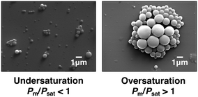 | ||
| Fig. 4 The average radius of submerging polymer particles can be increased by operating at a monomer partial pressure above the monomer saturation pressure. | ||
Polymer films
If the monomer is insoluble in the liquid and the spreading coefficient is positive, the polymer chains will spread to form a film. For example, the low surface energy fluoropolymer PPFDA has a positive spreading coefficient on all of the ILs and silicone oils we tested and therefore a dense film always forms at the vapor–liquid interface.54,64 If we incorporate a crosslinker, such as ethylene glycol diacrylate (EGDA), we can create mechanically robust polymer films of poly(1H,1H,2H,2H-perfluorodecyl acrylate-co-ethylene glycol diacrylate) [P(PFDA-co-EGDA)]. We showed the utility of these robust films by fabricating polymer canopies over micropillar arrays (Fig. 5).63 The canopies were fabricated by using either silicone oils or ILs as a physical mask to control the location of polymerization along the height of the pillars. The P(PFDA-co-EGDA) coating can also be used to encapsulate IL droplets using the concept of liquid marbles.56 Millimeter-sized droplets of 1-ethyl-3-methylimidazolium tetrafluoroborate [emim][BF4] were rolled on a bed of micron-sized PTFE particles to form the liquid marbles which were then coated within a P(PFDA-co-EGDA) shell. The PTFE particles were incorporated into the P(PFDA-co-EGDA) polymer shell, enhancing the mechanical strength of the coating (Fig. 5).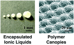 | ||
| Fig. 5 Polymer films can be used to encapsulate ionic liquids or to form polymer canopies over pillared arrays. | ||
The deposition of poly(ethylene glycol diacrylate) (PEGDA) on its own onto silicone oil should lead to polymer particles because of the negative spreading coefficient (S = −56 mN m−1), however a crosslinked microstructured polymer film forms due to the ability of EGDA to form crosslinks which allows for bridging of the polymer chains.55 The microstructured PEGDA films are composed of coral-like features that form because the polymer is favorably wetted by the silicone oil as it forms the crosslinked network. Since diffusion and aggregation play key roles in the formation of the microstructured film, the viscosity of the silicone oil impacts the surface roughness of the films. Increasing the viscosity of the silicone oil leads to slower diffusion and aggregation of the polymer chains which can be quantified by a decrease in the root-mean-squared surface roughness from ∼425 nm to ∼150 nm for 10 cSt and 500 cSt, respectively. We also showed that polymers that have a negative spreading coefficient can be crosslinked via copolymerization with EGDA to form similar microstructured films. For example, 1-vinyl-2-pyrrolidone (VP) and HEMA were copolymerized with EGDA to form microstructured films of P(VP-co-EGDA) and P(HEMA-co-EGDA) although the spreading coefficient values are −63 mN m−1 and −58 mN m−1 on silicone oil respectively.
Polymerization within the bulk
For cases where the monomer is soluble within the liquid, the liquid gets incorporated within the polymer structure. For example, HEMA is soluble in [emim][BF4] and polymerization leads to the formation of a gel due to the ability of PHEMA to form hydrogen bonds with the IL.23,66 Polymerization of HEMA occurs both at the vapor–liquid interface and within the IL leading to a bimodal distribution in molecular weight.8 For example, at a reactor pressure of 80 mTorr, deposition rate of 4 nm min−1, and deposition time of 5 min, the average molecular weight of the PHEMA chains formed at the vapor–liquid interface was 1.8 × 10⁴ Da with a PDI of 1.7 whereas the average molecular weight of the PHEMA chains formed within the IL was 1.2 × 10⁷ Da with a PDI of 1.8. The higher molecular weight of the chains formed within the IL is likely due to the higher propagation rates and reduced termination rates which is consistent with solution-phase polymerization within ILs.25,67 We also demonstrated that we could control the shape of the gel by polymerizing HEMA within spherical droplets of [emim][BF4].68 The IL droplets were kept spherical by placement on a rough hydrophobic surface. Monomer was then absorbed into the droplets and then the free radicals were generated afterward to initiate the polymerization process. By sequentially introducing the monomer and initiator radicals, surface polymerization was reduced which retained the hydrophobicity of the rough surface, maintaining the spherical shape of the gels. We can also fabricate thin free-standing gels by polymerizing HEMA on a layer of IL that is surrounded by a layer of silicone oil.64 A gel forms on the IL because HEMA is soluble whereas PHEMA particles form on the surrounding silicone oil because HEMA is insoluble. The silicone oil prevents the gel from being attached to the underlying silicon wafer and therefore the gel can be easily removed from the IL surface with tweezers.We have also shown that IL can be incorporated into copolymer films by studying the sequential and simultaneous polymerization of EGDA and PFDA onto [emim][BF4].60 EGDA is soluble in [emim][BF4], and therefore can absorb and polymerize in the bulk liquid, however PFDA is insoluble in the IL and only polymerizes at the vapor–liquid interface. In the case of simultaneous polymerization of both monomers, a heterogeneous film was formed. The top layer of the film was composed of P(PFDA-co-EGDA) copolymer formed at the vapor–liquid interface whereas the bottom layer was composed of both PEGDA and IL (PEGDA + IL) due to absorption of the EGDA monomer and subsequent bulk polymerization. An unexpected result occurred in the case of sequential deposition where first a layer of PPFDA was deposited onto the IL and then a layer of PEGDA was deposited onto the PPFDA. A PEGDA layer formed on top of the PPFDA layer as expected but interestingly, a PEGDA + IL layer was formed beneath the PPFDA layer indicating that the EGDA monomer and initiator radicals can diffuse through the dense PPFDA layer and absorbs into the IL. In the PEGDA + IL bottom layer, the ionic liquid is incorporated into the PEGDA layer through the entrapment of IL between the polymer chains formed in the bulk.
In all our previous examples, the liquid substrate does not covalently bond with the monomer. We can create covalent bonds between the liquid and monomer by using a polymerizable ionic liquid such as 1-ethyl-3-vinylimidazolium bis(trifluoromethylsulfonyl)imide ([EVIm][TFSI]), which contains a vinyl bond that can be copolymerized with EGDA monomer.61 Since EGDA is soluble in [EVIm][TFSI], it can be polymerized both within the liquid and at the vapor–liquid interface. This results in a gradient film with a PEGDA top layer and a poly([EVIm][TFSI]-co-EGDA) bottom layer. The deposition time and reactor pressure affect the IL concentration in the poly([EVIm][TFSI]-co-EGDA) copolymer layer because the growth of the PEGDA layer at the vapor–liquid interface reduces the flux of additional EGDA and initiator into the bulk liquid. We showed that these gradient films can be formed over wire meshes for additional stability for potential applications in separations, ion conducting membranes, and catalysis.61
Concluding remarks
Our studies have demonstrated the effects of surface tension and viscosity during iCVD onto liquid substrates. In order to understand whether these relationships govern the deposition of materials during other vapor phase deposition processes, we recently studied DC magnetron sputter deposition of gold and silver onto a variety of liquids of different viscosities and surface tensions.30 We found that the trends were analogous to polymer deposition since metal sputtered onto low viscosity silicone oils (≤100 cSt) and ILs formed nanoparticle dispersions, whereas metal sputtered onto high viscosity silicone oils (≥350 cSt) formed films. Since the trends in iCVD and sputtering onto liquid substrates are similar, we were able to combine these two processes to create unique organic/inorganic hybrid materials.53 For example, we fabricated polymer nanoparticles decorated with metal nanoparticles using a submerging polymer particle system. We also fabricated a gel with embedded nanoparticles using a soluble monomer-IL system. In the above examples, there is passive motion during deposition due to diffusion and surface tension effects. We recently demonstrated that we can introduce active motion by modifying the iCVD reactor with a speaker to produce standing waves on the liquid surface.69 Our studies showed that crosslinking was required to form continuous films on the agitated vapor–liquid interface and the mechanical stability of the films can be enhanced by increasing the film thickness. Our understanding of interactions at the vapor–liquid interface during inorganic and organic deposition and our ability to actively modulate the liquid surface can enable the development of a new generation of hybrid reactors with in situ capabilities.Conflicts of interest
There are no conflicts to declare.Acknowledgements
M. D. L. is supported by a National Science Foundation Graduate Research Fellowship under grant DGE-1418060.References
- M. E. Alf, A. Asatekin, M. C. Barr, S. H. Baxamusa, H. Chelawat, G. Ozaydin-lnce, C. D. Petruczok, R. Sreenivasan, W. E. Tenhaeff, N. J. Trujillo, S. Vaddiraju, J. Xu and K. K. Gleason, Adv. Mater., 2010, 22, 1993–2027 CrossRef CAS.
- W. E. Tenhaeff and K. K. Gleason, Adv. Funct. Mater., 2008, 18, 979–992 CrossRef CAS.
- S. Seidel, C. Riche and M. Gupta, in Encyclopedia of Polymer Science and Technology, John Wiley & Sons, Inc., 2011 Search PubMed.
- K. K. S. Lau and K. K. Gleason, Macromolecules, 2006, 39, 3688–3694 CrossRef CAS.
- K. K. S. Lau and K. K. Gleason, Macromolecules, 2006, 39, 3695–3703 CrossRef CAS.
- G. Ozaydin-Ince and K. K. Gleason, J. Vac. Sci. Technol., A, 2009, 27, 1135–1143 CrossRef CAS.
- M. Gupta and K. K. Gleason, Langmuir, 2006, 22, 10047–10052 CrossRef CAS.
- R. J. Frank-Finney, L. C. Bradley and M. Gupta, Macromolecules, 2013, 46, 6852–6857 CrossRef CAS.
- R. K. Bose and K. K. S. Lau, Biomacromolecules, 2010, 11, 2116–2122 CrossRef CAS PubMed.
- S. H. Baxamusa and K. K. Gleason, Chem. Vap. Deposition, 2008, 14, 313–318 CrossRef CAS.
- M. Gupta and K. K. Gleason, Thin Solid Films, 2009, 517, 3547–3550 CrossRef CAS.
- J. Xu and K. K. Gleason, ACS Appl. Mater. Interfaces, 2011, 3, 2410–2416 CrossRef CAS.
- B. Chen, P. Kwong and M. Gupta, ACS Appl. Mater. Interfaces, 2013, 5, 12701–12707 CrossRef CAS.
- P. Kwong, C. A. Flowers and M. Gupta, Langmuir, 2011, 27, 10634–10641 CrossRef CAS.
- P. Kwong and M. Gupta, Anal. Chem., 2012, 84, 10129–10135 CrossRef CAS.
- M. Gupta, V. Kapur, N. M. Pinkerton and K. K. Gleason, Chem. Mater., 2008, 20, 1646–1651 CrossRef CAS.
- A. Asatekin and K. K. Gleason, Nano Lett., 2011, 11, 677–686 CrossRef CAS.
- R. Yang and K. K. Gleason, Langmuir, 2012, 28, 12266–12274 CrossRef CAS.
- Y. Ye, Y. Mao, F. Wang, H. Lu, L. Qu and L. Dai, J. Mater. Chem., 2011, 21, 837–842 RSC.
- E. D. Laird, R. K. Bose, W. Wang, K. K. S. Lau and C. Y. Li, Macromol. Rapid Commun., 2013, 34, 251–256 CrossRef CAS.
- C. T. Riche, B. C. Marin, N. Malmstadt and M. Gupta, Lab Chip, 2011, 11, 3049–3052 RSC.
- C. T. Riche, C. Zhang, M. Gupta and N. Malmstadt, Lab Chip, 2014, 14, 1834–1841 RSC.
- T. Ueki and M. Watanabe, Bull. Chem. Soc. Jpn., 2012, 85, 33–50 CrossRef CAS.
- P. C. Marr and A. C. Marr, Green Chem., 2015, 18, 105–128 RSC.
- P. Kubisa, Prog. Polym. Sci., 2004, 29, 3–12 CrossRef CAS.
- J. P. Xie, W. Y. Yu, S. L. Zhang, M. G. Chen and G. X. Ye, Phys. Lett. A, 2007, 371, 160–164 CrossRef CAS.
- M. Wagener and B. Günther, J. Magn. Magn. Mater., 1999, 201, 41–44 CrossRef CAS.
- D. Sugioka, T. Kameyama, S. Kuwabata and T. Torimoto, Phys. Chem. Chem. Phys., 2015, 17, 13150–13159 RSC.
- H. Wender, L. F. De Oliveira, P. Migowski, A. F. Feil, E. Lissner, M. H. G. Prechtl, S. R. Teixeira and J. Dupont, J. Phys. Chem. C, 2010, 114, 11764–11768 CrossRef CAS.
- M. M. De Luna and M. Gupta, Appl. Phys. Lett., 2018, 112, 201605 CrossRef.
- C. Feng, H. Ge, M. Tong, G. Ye and Z. Jiao, Thin Solid Films, 1999, 342, 30–34 CrossRef.
- E. F. Borra, O. Seddiki, R. Angel, D. Eisenstein, P. Hickson, K. R. Seddon and S. P. Worden, Nature, 2007, 447, 979–981 CrossRef CAS.
- G. Ye, Q. Zhang, C. Feng, H. Ge and Z. Jiao, Phys. Rev. B: Condens. Matter Mater. Phys., 1996, 54, 14754–14757 CrossRef CAS.
- P. Cai, S. Yu, X. Xu, M. Chen, C. Sui and G. X. Ye, Appl. Surf. Sci., 2009, 255, 8352–8358 CrossRef CAS.
- M.-G. Chen, J.-P. Xie and G.-X. Ye, Phys. Lett. A, 2006, 360, 323–326 CrossRef CAS.
- B. Yang, R.-R. Ma, D.-M. Li, A.-G. Xia and X.-M. Tao, Thin Solid Films, 2012, 520, 2321–2325 CrossRef CAS.
- T. Torimoto, K. I. Okazaki, T. Kiyama, K. Hirahara, N. Tanaka and S. Kuwabata, Appl. Phys. Lett., 2006, 89, 243117 CrossRef.
- Y. Hatakeyama, T. Morita, S. Takahashi, K. Onishi and K. Nishikawa, J. Phys. Chem. C, 2011, 115, 3279–3285 CrossRef CAS.
- Y. Hatakeyama, K. Onishi and K. Nishikawa, RSC Adv., 2011, 1, 1815–1821 RSC.
- C.-H. Liu, B.-H. Mao, J. Gao, S. Zhang, X. Gao, Z. Liu, S.-T. Lee, X.-H. Sun and S.-D. Wang, Carbon, 2012, 50, 3008–3014 CrossRef CAS.
- K. Ueno and H. Misawa, J. Photochem. Photobiol., C, 2013, 15, 31–52 CrossRef CAS.
- N. Binh-Khiem, K. Matsumoto and I. Shimoyama, Langmuir, 2010, 26, 18771–18775 CrossRef PubMed.
- J. T. Wu, C. Y. Wu, S. K. Fan, C. C. Hsieh, Y. C. Hou and H. Y. Chen, Chem. Mater., 2015, 27, 7028–7033 CrossRef CAS.
- N. Binh-Khiem, K. Matsumoto and I. Shimoyama, Appl. Phys. Lett., 2008, 93, 2006–2009 CrossRef.
- P. D. Haller, R. J. Frank-Finney and M. Gupta, Macromolecules, 2011, 44, 2653–2659 CrossRef CAS.
- G. Vilar, J. Tulla-Puche and F. Albericio, Curr. Drug Delivery, 2012, 9, 367–394 CrossRef CAS.
- S. Pathak, M. T. Greci, R. C. Kwong, K. Mercado, G. K. S. Prakash, G. A. Olah and M. E. Thompson, Chem. Mater., 2000, 12, 1985–1989 CrossRef CAS.
- Y. Shi, M. Wang, C. Ma, Y. Wang, X. Li and G. Yu, Nano Lett., 2015, 15, 6276–6281 CrossRef CAS.
- G. Ruan, G. Vieira, T. Henighan, A. Chen, D. Thakur, R. Sooryakumar and J. O. Winter, Nano Lett., 2010, 10, 2220–2224 CrossRef CAS.
- L. L. Chng, N. Erathodiyil and J. Y. Ying, Acc. Chem. Res., 2013, 46, 1825–1837 CrossRef CAS PubMed.
- A. Dokoutchaev, J. T. James, S. C. Koene, S. Pathak, G. K. S. Prakash and M. E. Thompson, Chem. Mater., 1999, 11, 2389–2399 CrossRef CAS.
- W. Li, Q. Liu and L. Liu, Langmuir, 2014, 30, 12619–12626 CrossRef CAS PubMed.
- M. M. De Luna, P. Karandikar and M. Gupta, ACS Appl. Nano Mater., 2018, 1, 6575–6579 CrossRef CAS.
- P. D. Haller, L. C. Bradley and M. Gupta, Langmuir, 2013, 29, 11640–11645 CrossRef CAS.
- L. C. Bradley and M. Gupta, Langmuir, 2015, 31, 7999–8005 CrossRef CAS.
- L. C. Bradley and M. Gupta, Langmuir, 2012, 28, 10276–10280 CrossRef CAS PubMed.
- R. J. Frank-Finney and M. Gupta, Langmuir, 2016, 32, 11014–11020 CrossRef CAS PubMed.
- P. Karandikar and M. Gupta, Langmuir, 2017, 33, 7701–7707 CrossRef CAS PubMed.
- P. D. Haller and M. Gupta, Macromol. Rapid Commun., 2014, 35, 2000–2004 CrossRef CAS PubMed.
- L. C. Bradley and M. Gupta, Langmuir, 2013, 29, 10448–10454 CrossRef CAS PubMed.
- L. C. Bradley and M. Gupta, Macromolecules, 2014, 47, 6657–6663 CrossRef CAS.
- H. W. Fox and W. A. Zisman, J. Colloid Sci., 1952, 7, 109–121 CrossRef CAS.
- B. Chen, R. J. Frank-Finney and M. Gupta, ACS Appl. Mater. Interfaces, 2015, 7, 23056–23061 CrossRef CAS.
- R. J. Frank-Finney, P. D. Haller and M. Gupta, Macromolecules, 2012, 45, 165–170 CrossRef CAS.
- S. E. Anachkov, I. Lesov, M. Zanini, P. A. Kralchevsky, N. D. Denkov and L. Isa, Soft Matter, 2016, 12, 7632–7643 RSC.
- Z. Li, H. Liu, Y. Liu, P. He, J. Li, L. Zheng and J. Li, Polymer, 2005, 46, 7578–7584 CrossRef CAS.
- S. Harrisson, S. R. Mackenzie and D. M. Haddleton, Macromolecules, 2003, 36, 5072–5075 CrossRef CAS.
- P. Karandikar and M. Gupta, Thin Solid Films, 2017, 635, 17–22 CrossRef CAS.
- P. Karandikar, M. M. De Luna and M. Gupta, ACS Appl. Polym. Mater., 2019, 1, 1930–1934 CrossRef CAS.
| This journal is © The Royal Society of Chemistry 2020 |


