 Open Access Article
Electrode initiated proton-coupled electron transfer to promote degradation of a nickel(II) coordination complex†
Brian D.
McCarthy
a,
Carrie L.
Donley
b and
Jillian L.
Dempsey
*a
aDepartment of Chemistry, University of North Carolina, Chapel Hill, North Carolina 27599-3290, USA. E-mail: dempseyj@email.unc.edu
bChapel Hill Analytical and Nanofabrication Laboratory, Department of Applied Physical Sciences, University of North Carolina, Chapel Hill, North Carolina 27599-3216, USA
First published on 5th March 2015
Abstract
A Ni(II) bisphosphine dithiolate compound degrades into an electrode-adsorbed film that can evolve hydrogen under reducing and protic conditions. An electrochemical study suggests that the degradation mechanism involves an initial concerted proton–electron transfer. The potential susceptibility of Ni–S bonds in molecular hydrogen evolution catalysts to degradation via C–S bond cleavage is discussed.
Introduction
The decomposition of molecular catalysts can limit the lifetime of their activity and hinder mechanistic study.1,2 Given the tremendous effort applied to developing new catalysts for areas of societal importance, including sunlight-to-fuel schemes,3,4 identifying when catalysts are decomposing,5 understanding the mechanisms by which catalysts decompose, and recognizing what structural factors predispose a catalyst towards degradation is of importance. To date, most work has focused on identifying only if a molecular complex degrades into a catalytically competent heterogeneous species, a non-trivial task.1,5Electrocatalysis is an attractive means of converting electrical energy into chemical fuels like hydrogen.3,4,6 Several wireless device structures have been proposed which integrate catalysts with light absorbing molecules and materials to drive fuel production from sunlight.6–13 Many molecular electrocatalysts have been prepared which convert protons into hydrogen at excellent efficiencies in both aqueous and non-aqueous solutions.3,4,14,15 While a few reports have discussed the general instability of electrocatalysts,5,16,17 work in the last few years has begun explicitly investigating the instability of certain molecular electrochemical catalysts under reducing and protic conditions.2,18–24 In each of these cases degradation resulted in a heterogeneous material still active for hydrogen evolution.
Studies of catalyst stability have largely focused on reporting which molecular compounds degrade electrochemically and characterizing the catalytically active material they form, though some effort has been directed towards determining the mechanisms by which these processes occur. Degradation pathways have been proposed to occur through initial ligand modification,19–22,24,25 such as hydrogenation of C![[double bond, length as m-dash]](https://www.rsc.org/images/entities/char_e001.gif) N bonds, for some complexes. Interpreting the reaction pathways for catalyst modification under electrocatalytic conditions is particularly challenging, as the species of interest transforms from a molecular complex to a heterogeneous species, such as nanoparticles or an amorphous film, during the course of the reaction. Equally challenging, reactivity under reducing and protic conditions typically involves proton-coupled electron transfer (PCET) processes, which can occur via stepwise or concerted pathways and can be difficult to distinguish. Understanding the details of PCET processes in molecular electrocatalysis—whether it leads to productive fuel production or it prompts catalyst degradation—is essential for interpreting the free-energy landscape of these systems.26–31 Herein we examine the reactivity of a nickel(II) compound (1, Scheme 1), which has several structural motifs of interest for molecular hydrogen evolving catalyst design, including a bisphosphine backbone and a dithiolate ligand. Upon identifying that 1 degrades under electrocatalytic conditions, intriguing features were observed in the voltammograms, prompting us to examine the pathway of degradation. In this study, we reveal unique PCET reactivity that is promoted under electrocatalytic conditions and ultimately leads to degradation and formation of a heterogeneous active species.
N bonds, for some complexes. Interpreting the reaction pathways for catalyst modification under electrocatalytic conditions is particularly challenging, as the species of interest transforms from a molecular complex to a heterogeneous species, such as nanoparticles or an amorphous film, during the course of the reaction. Equally challenging, reactivity under reducing and protic conditions typically involves proton-coupled electron transfer (PCET) processes, which can occur via stepwise or concerted pathways and can be difficult to distinguish. Understanding the details of PCET processes in molecular electrocatalysis—whether it leads to productive fuel production or it prompts catalyst degradation—is essential for interpreting the free-energy landscape of these systems.26–31 Herein we examine the reactivity of a nickel(II) compound (1, Scheme 1), which has several structural motifs of interest for molecular hydrogen evolving catalyst design, including a bisphosphine backbone and a dithiolate ligand. Upon identifying that 1 degrades under electrocatalytic conditions, intriguing features were observed in the voltammograms, prompting us to examine the pathway of degradation. In this study, we reveal unique PCET reactivity that is promoted under electrocatalytic conditions and ultimately leads to degradation and formation of a heterogeneous active species.
Results and discussion
Characterization of 1
Compound 1 was prepared in 15% yield via a related approach to a previously reported derivative of 1 with a methyl amine group at the bridgehead of the phosphine (see ESI† for details).32 One- and two-dimensional NMR confirmed the structure of 1 shown in Scheme 1 (Fig. S1–S5†). A reversible, one-electron wave assigned to the NiII/I couple is observed via cyclic voltammetry (CV) with an E1/2 of −1.92 V as well as an irreversible oxidation attributed to the NiIII/II couple with Ep,a = −0.34 V (Fig. 1). The redox properties of 1 are very similar to the previously reported methyl amine derivative.32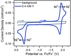 | ||
| Fig. 1 Cyclic voltammogram of 0.4 mM 1 at 100 mV s−1 in 0.25 M [Bu4N][PF6] acetonitrile solution. The NiII/I couple has an E1/2 of −1.92 V and the irreversible NiIII/II couple has an Ep,a of −0.34 V. | ||
Scan rate studies of the NiII/I couple reveal that 1 is under diffusion control (Fig. S8†), as expected for a homogeneous species, with a diffusion coefficient of 1 × 10⁻⁵ cm2 s−1 (Fig. S9†). The Nicholson method33 was used to estimate a value of 0.1 cm s−1 for the heterogeneous electron transfer rate constant (k0) of the NiII/I couple (see ESI for details†).
Electrochemistry of 1 in the presence of acid
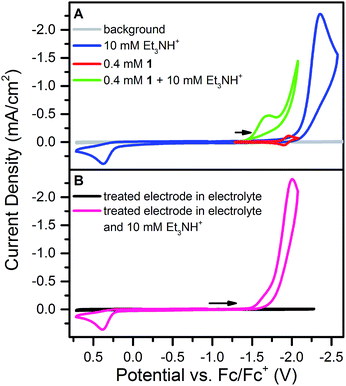
Addition of 10 mM [Et3NH][BF4] (pKa = 18.82 in CH3CN34) to a solution of 1 results in loss of the reversible NiII/I wave and the appearance of two irreversible waves, both positive of the direct electrode reduction of [Et3NH][BF4] as shown in Fig. 2A. The large current of the second wave suggests proton reduction catalysis. The onset of the first wave occurs hundreds of millivolts positive of the NiII/I reduction. Prewaves preceding apparent catalytic waves have been observed previously for nickel and cobalt complexes and in these cases assigned to either ligand hydrogenation or decomposition of the initial molecular species into a heterogeneous, electrode adsorbed material.19,20,22,231 was also found to transform into an electrode-bound active species via a rinse test: in a solution of 1 and 10 mM [Et3NH][BF4], an electrode was scanned through the prewave and second wave, rinsed with acetonitrile and transferred to a solution of only 10 mM [Et3NH][BF4]. In this acid-only solution, the catalytic response was maintained (Fig. 2B). Dipping an electrode in a solution of 1 and 10 mM [Et3NH][BF4] without applied bias did not produce the same result.Characterization of modified electrodes
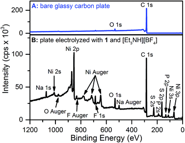
X-ray photoelectron spectroscopy (XPS) and scanning electron microscopy (SEM) were used to characterize the electrode surface after treatment with 1 and [Et3NH][BF4]. SEM of glassy carbon plate electrodes electrolyzed in solutions of 1 and [Et3NH][BF4] revealed the presence of a smooth film with no evidence for discrete particles (Fig. S10 and S11†), contrasting similar studies where nanoparticle deposition was observed.19,20,22,24XPS analysis of a bare glassy carbon plate revealed the presence of only carbon and oxygen (Fig. 3A), as expected for glassy carbon which normally has surface oxygen moieties.35 Plates electrolyzed with 1 and [Et3NH][BF4], however, were found to have additional elements (Fig. 3B) including Ni, F, S, and P. For comparison, XPS spectra were obtained for dropcast samples of 1, [Bu4N][PF6], [Et3NH][BF4], and bis(diphenylphosphino)propane (see ESI†). The relative atomic ratios of Ni![[thin space (1/6-em)]](https://www.rsc.org/images/entities/char_2009.gif) :
:![[thin space (1/6-em)]](https://www.rsc.org/images/entities/char_2009.gif) S
S![[thin space (1/6-em)]](https://www.rsc.org/images/entities/char_2009.gif) :
:![[thin space (1/6-em)]](https://www.rsc.org/images/entities/char_2009.gif) P in the dropcast spectrum of 1 were 1
P in the dropcast spectrum of 1 were 1![[thin space (1/6-em)]](https://www.rsc.org/images/entities/char_2009.gif) :
:![[thin space (1/6-em)]](https://www.rsc.org/images/entities/char_2009.gif) 1.8
1.8![[thin space (1/6-em)]](https://www.rsc.org/images/entities/char_2009.gif) :
:![[thin space (1/6-em)]](https://www.rsc.org/images/entities/char_2009.gif) 2 (Fig. S14 and Table S5†), as expected for a species with two sulfur and two phosphorus atoms per nickel atom. In contrast, the relative atomic ratios of Ni
2 (Fig. S14 and Table S5†), as expected for a species with two sulfur and two phosphorus atoms per nickel atom. In contrast, the relative atomic ratios of Ni![[thin space (1/6-em)]](https://www.rsc.org/images/entities/char_2009.gif) :
:![[thin space (1/6-em)]](https://www.rsc.org/images/entities/char_2009.gif) S
S![[thin space (1/6-em)]](https://www.rsc.org/images/entities/char_2009.gif) :
:![[thin space (1/6-em)]](https://www.rsc.org/images/entities/char_2009.gif) P in the electrolyzed sample were 1
P in the electrolyzed sample were 1![[thin space (1/6-em)]](https://www.rsc.org/images/entities/char_2009.gif) :
:![[thin space (1/6-em)]](https://www.rsc.org/images/entities/char_2009.gif) 1.23
1.23![[thin space (1/6-em)]](https://www.rsc.org/images/entities/char_2009.gif) :
:![[thin space (1/6-em)]](https://www.rsc.org/images/entities/char_2009.gif) 0.34 indicating that the deposited material has substantially different atomic stoichiometry than 1. While the XPS binding energy positions for the Ni 2p and S 2p peaks in the high resolution spectra of electrolyzed 1 (Fig. S16 and S17†) did not permit unambiguous assignment of the species, nickel metal – with a binding energy of 852.6 eV36 – can be ruled out, at least within the XPS sampling depth (∼10 nm). The Ni 2p peak at 853.9 eV may possibly represent the presence of nickel sulfide; NiS was recently suggested to be the electro-decomposition product of [Ni(bdt)2][Bu4N] under protic and reducing conditions.23
0.34 indicating that the deposited material has substantially different atomic stoichiometry than 1. While the XPS binding energy positions for the Ni 2p and S 2p peaks in the high resolution spectra of electrolyzed 1 (Fig. S16 and S17†) did not permit unambiguous assignment of the species, nickel metal – with a binding energy of 852.6 eV36 – can be ruled out, at least within the XPS sampling depth (∼10 nm). The Ni 2p peak at 853.9 eV may possibly represent the presence of nickel sulfide; NiS was recently suggested to be the electro-decomposition product of [Ni(bdt)2][Bu4N] under protic and reducing conditions.23
To assess the hydrogen evolution ability of the deposited material, a glassy carbon plate was held at −1.7 V for 10 minutes in a solution of 0.4 mM 1 and 10 mM [Et3NH][BF4]. After rinsing the electrode, the plate was held at −1.7 V vs. Fc/Fc+ in a bulk electrolysis cell containing 25 mM [Et3NH][BF4] for 15 minutes. Sampling of the headspace by gas chromatography confirmed the production of hydrogen with a Faradaic efficiency of approximately 100% (see ESI† for experimental details).
Proton-coupled electron transfer pathways
Understanding the mechanism by which a catalyst degrades can help inform strategies to protect against degradation in future systems. Consequently, mechanistic details of the initial electrochemically-initiated steps leading to decomposition of 1 were probed. Specifically, we sought to examine the PCET process that initiates structural modification of 1. How many protons and electrons are initially transferred to the molecular species? Do the electron transfer (ET) and proton transfer (PT) steps occur sequentially or through a concerted process?37 While some mechanistic insight to PCET processes in molecular hydrogen-evolving electrocatalysts have been provided through both theoretical29–31,37,38 and electrochemical27,28,39 studies, examining PCET in our system is complicated by the fact that these steps are part of a degradation mechanism which ultimately produces an ill-defined heterogeneous material. To minimize complications, we examined the PCET reactivity at stoichiometric and sub-stoichiometric acid-catalyst ratios (up to one equivalent of acid), allowing us to determine how PCET modification proceeds when only one equivalent of protons is present. Even under these limiting conditions, caution was necessary when interpreting results: the larger diffusion coefficient of [Et3NH+] relative to 1 (see below) means that even for solutions prepared with 1![[thin space (1/6-em)]](https://www.rsc.org/images/entities/char_2009.gif) :
:![[thin space (1/6-em)]](https://www.rsc.org/images/entities/char_2009.gif) 1 ratios of 1
1 ratios of 1![[thin space (1/6-em)]](https://www.rsc.org/images/entities/char_2009.gif) :
:![[thin space (1/6-em)]](https://www.rsc.org/images/entities/char_2009.gif) [Et3NH+] more than one equivalent of [Et3NH+] per molecule of 1 can arrive at the electrode on the CV time scale.
[Et3NH+] more than one equivalent of [Et3NH+] per molecule of 1 can arrive at the electrode on the CV time scale.
To approximate a 1![[thin space (1/6-em)]](https://www.rsc.org/images/entities/char_2009.gif) :
:![[thin space (1/6-em)]](https://www.rsc.org/images/entities/char_2009.gif) 1 ratio of 1
1 ratio of 1![[thin space (1/6-em)]](https://www.rsc.org/images/entities/char_2009.gif) :
:![[thin space (1/6-em)]](https://www.rsc.org/images/entities/char_2009.gif) [Et3NH+], a solution of [Et3NH+] was titrated into a solution of 1 and the reversible NiII/I wave of 1 monitored by CV until reversibility was lost. Assuming that acid at the electrode preferentially reacts irreversibly with unreacted 1, complete loss of the reversible wave of 1 should indicate an approximate 1
[Et3NH+], a solution of [Et3NH+] was titrated into a solution of 1 and the reversible NiII/I wave of 1 monitored by CV until reversibility was lost. Assuming that acid at the electrode preferentially reacts irreversibly with unreacted 1, complete loss of the reversible wave of 1 should indicate an approximate 1![[thin space (1/6-em)]](https://www.rsc.org/images/entities/char_2009.gif) :
:![[thin space (1/6-em)]](https://www.rsc.org/images/entities/char_2009.gif) 1 ratio of 1
1 ratio of 1![[thin space (1/6-em)]](https://www.rsc.org/images/entities/char_2009.gif) :
:![[thin space (1/6-em)]](https://www.rsc.org/images/entities/char_2009.gif) [Et3NH+].
[Et3NH+].
With one equivalent of [Et3NH][BF4] the resulting irreversible prewave (Fig. 4) corresponds to the transfer of about two electrons, as determined via current integration. As might be expected for a system undergoing degradation, it was difficult to reliably measure exactly two electrons each time this experiment was repeated; however, the number of electrons passed was consistently found to be between 1.5 and 2. A scan rate study of this new irreversible wave found that the peak current varied linearly with the square root of the scan rate (Fig. S18†), as expected for a freely diffusing species, indicating that the 2-electron/1-proton electrochemistry occurs in solution and not on the electrode surface.40 We suggest that this proton–electron reactivity forms a hydride species, a putative intermediate in many catalytic cycles for the Ni-mediated formation of H2.41–43
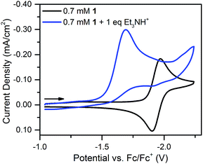 | ||
| Fig. 4 Cyclic voltammograms of 0.7 mM 1 and 0.7 mM 1 plus one equivalent of [Et3NH][BF4]. Recorded at 100 mV s−1 in 0.1 M [Bu4N][PF6]. | ||
Notably, the peak of this irreversible prewave appears ca. 0.28 V positive of the cathodic peak position of the reversible wave of 1 observed in the absence of [Et3NH][BF4]. In order to explain this large positive shift for the two-electron irreversible wave with one equivalent of acid present, we recognized that the coupled one proton and two electron transfers that give rise to this prewave can occur through stepwise (sequential) mechanisms or involve concerted proton–electron transfer (CPET). Specifically, we considered a stepwise PT–ET–ET mechanism (an electrochemical CEE mechanism), a stepwise ET–PT–ET mechanism (an electrochemical ECE mechanism), and a CPET–ET process (here denoted (EC)concertedE) (Fig. 5).
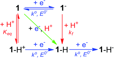 | ||
| Fig. 5 Square scheme depicting possible mechanisms for addition of two electrons and one proton to compound 1. Relevant constants are indicated. | ||
A CEE mechanism which produces a new intermediate 1–H+ would be expected to be more easily reduced than 1 by virtue of the positive charge and so account for the 0.28 V potential shift. A variation of this mechanism is transient formation of a hydrogen-bonded complex. Intramolecular hydrogen bonding has been used to explain the positive peak shifts of the electrochemistry of organic molecules44 and inorganic compounds (e.g., the “hangman effect”).29 Neither UV-vis or 1H NMR found any evidence of interaction between 1 and over 100 molar equivalents of [Et3NH][BF4] (see ESI†). This lack of evidence does not rule out transient interactions producing an undetectable population of 1–H+ or hydrogen-bonded 1, but no evidence supporting a CEE mechanism was found.
An EC-type pathway could also explain the positive shift of the reduction wave in the presence of protons.28,29 For a ErCi mechanism (reversible electron transfer followed by irreversible chemical reaction)
| Er: P + e− ⇌ Q |
the magnitude of the rate constant k can have a dramatic effect on the CV peak position and shape. In the absence of reactant A, electron transfer, if reversible and Nernstian, results in predictable relative concentrations of P and Q at the electrode surface based on the reduction potential.40,45 Even at potentials sufficiently positive of the formal reduction potential, small concentrations of the reduced species Q will still exist, as predicted by the Nernst equation. If Q reacts with substrate A to irreversibly form species QA, more Q will be produced near the electrode to maintain equilibrium. For large rate constants this results in a shift of the peak to potentials more positive than the formal reduction potential, as shown by simulation in Fig. 6A for an ErCiEi process. The peak shift magnitude is dependent on both the heterogeneous electron transfer rate constant k0 (cm s−1) for the P/Q couple and the second order forward rate constant k (M−1 s−1). For the simpler ErCi mechanism the new peak position Ep is given by29,46
where k is the rate of the chemical step (e.g., protonation, kobs = k[A]). As the mechanism here involves a second electron transfer, digital simulations were performed to model the peak shift.
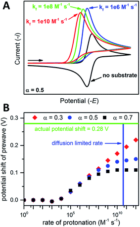 | ||
| Fig. 6 (A) Simulated CVs for an ErCiEi reaction. (B) Prewave potential shift (relative to the cathodic peak of the original reversible wave) versus the rate of protonation. The horizontal green line indicates the experimentally observed peak shift while the vertical blue line indicates the estimated diffusion limited rate for 1 and [Et3NH][BF4], see text for details. Simulated with DigiElch: α = 0.5 for (A) and 0.3, 0.5, or 0.7 as indicated for (B); k0 = 0.1 cm s−1 for both E steps; [P] = [A] = 0.005 M; surface area of electrode = 0.071 cm2; α = 0.5 used for E of second electron transfer where E2 was 0.5 V more positive than the E for the first step (see ESI† for details). | ||
Prior to simulation, several constants were estimated experimentally. As described above, k0 for 1 was estimated by the Nicholson method to be 0.1 cm s−1. The rate constant k is unknown; however, the upper limit for k is expected to be the diffusion limited rate kdiff, which is the maximum rate two reactants can diffuse to one another in solution. The value kdiff was estimated using the Debye–Smoluchowski relation47
| kdiff = 4πNA(D1 + D2)β |
With an ECE mechanism found theoretically implausible by digital simulations and with no evidence of a CEE mechanism, a concerted (EC)concertedE mechanism was considered. For concerted pathways not involving heavy atom bond cleavage48 electrochemical kinetic isotope effects have been used as a diagnostic for CPET.49–54 Therefore, cyclic voltammograms were obtained of 1 in the presence of sub-stoichiometric amounts of [Et3NH][Cl] (to permit observation of the position of 1's reversible wave) and either 0.24 M H2O or 0.24 M D2O. These solutions were allowed to equilibrate for ca. 5 minutes after addition of H2O/D2O. The chloride salt rather than the BF4− salt of Et3NH+ was utilized to avoid the possibility of BF4− hydrolysis.55 A clear kinetic isotope effect is observed with a difference in prewave peak positions of ca. 20 mV (Fig. 7). This is consistent with a concerted pathway where simultaneous transfer of a proton with the electron reduces the magnitude of the applied potential necessary for reduction by decreasing buildup of negative charge on 1 in the transition state. This data consequently supports a CPET to 1 followed by a second reduction as the initial mechanism of degradation.
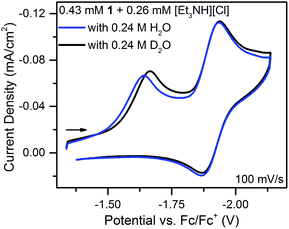 | ||
| Fig. 7 Cyclic voltammograms of equimolar solutions of 1 with sub-stoichiometric [Et3NH][Cl] and either 0.24 M H2O or D2O. | ||
Structural features impacting stability
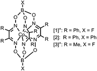
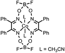
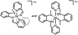
The decomposition of hydrogen-evolving catalysts into surface-adsorbed catalytically active species has only recently received dedicated attention. A summary of complexes reported to electrochemically decompose into electrode adsorbed materials active for hydrogen evolution in acetonitrile is presented in Table 1. Although at present the dataset is small, clear structural similarities have emerged that may bias a complex towards decomposition. Specifically, complexes with C![[double bond, length as m-dash]](https://www.rsc.org/images/entities/char_e001.gif) N or N–O bonds, which are reported to be susceptible to hydrogenation and hydrogenolysis, respectively, make up the majority of the reports.
N or N–O bonds, which are reported to be susceptible to hydrogenation and hydrogenolysis, respectively, make up the majority of the reports.
| Molecule | Key structural features | Acid | Decomposition product | Ref. (year) |
|---|---|---|---|---|
| a This table does not include examples where the homogeneous catalyst only degrades after harsh prolonged catalysis; e.g., ref. 56. | ||||
|
C![[double bond, length as m-dash]](https://www.rsc.org/images/entities/char_e001.gif) N and N–O bonds N and N–O bonds |
HClO4 | Co and O containing nanoparticles | 19, 20 (2012, 2013) |

|
C![[double bond, length as m-dash]](https://www.rsc.org/images/entities/char_e001.gif) N and N–O bonds N and N–O bonds |
CF3COOH/Et3NH+/CH3COOH | Co and O containing nanocubes | 21 (2013) |
|
C![[double bond, length as m-dash]](https://www.rsc.org/images/entities/char_e001.gif) N bonds N bonds |
HClO4 | Co and O containing nanoparticles | 22 (2014) |

|
C![[double bond, length as m-dash]](https://www.rsc.org/images/entities/char_e001.gif) N and N–O bonds N and N–O bonds |
HClO4 | Ni containing nanoparticles | 24 (2014) |

|
Ni–S bonds | 4-Br-anilinium | Ni/S containing film | 23 (2014) |
|
C![[double bond, length as m-dash]](https://www.rsc.org/images/entities/char_e001.gif) N bonds, Ni–S bonds N bonds, Ni–S bonds |
CF3COOH | Ni/S containing amorphous film with embedded nanoparticles | 25 (2015) |

|
Ni–S bonds | Et3NH+ | Ni/S containing amorphous film | This work |
The last two literature examples in Table 1 show cases without C![[double bond, length as m-dash]](https://www.rsc.org/images/entities/char_e001.gif) N or N–O bonds and this work adds a third example of a complex lacking C
N or N–O bonds and this work adds a third example of a complex lacking C![[double bond, length as m-dash]](https://www.rsc.org/images/entities/char_e001.gif) N or N–O bonds that also degrades. Notably, these three complexes all have Ni–S bonds, indicating that Ni–S bonds may render a complex susceptible to degradation under reducing and protic conditions. CV data featuring catalytic prewaves exists for other Ni–S species proposed to be molecular electrocatalysts,57,58 suggesting that these compounds may also decompose, possibly into heterogeneous species also active for hydrogen evolution.
N or N–O bonds that also degrades. Notably, these three complexes all have Ni–S bonds, indicating that Ni–S bonds may render a complex susceptible to degradation under reducing and protic conditions. CV data featuring catalytic prewaves exists for other Ni–S species proposed to be molecular electrocatalysts,57,58 suggesting that these compounds may also decompose, possibly into heterogeneous species also active for hydrogen evolution.
The formation of Ni/S containing material upon degradation of 1 suggests degradation of the organosulfur ligands. While no literature was found explicitly for electrochemical C–S cleavage by nickel, numerous examples of Ni-catalyzed desulfurization of C–S bonds have been reported. Ni compounds have been found to insert into C–S bonds, occasionally releasing the alkyl group if a hydride equivalent is available, including the example presented in Scheme 2.59–63
 | ||
| Scheme 2 Literature example of Ni mediated S–C bond cleavage.63 | ||
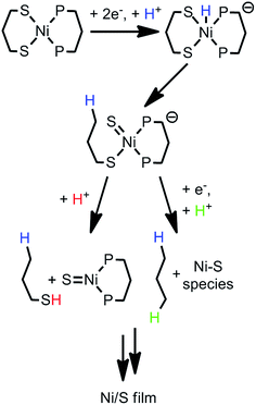
While nickel hydrides are not necessary for desulfurization,60,61 they are implicated in some cases of Ni-mediated C–S cleavage.59 In the case of compound 1, it is plausible that initial formation of a nickel hydride then initiates C–S cleavage in the 1,3-propanedithiolate ligand. Scheme 3 presents two possible pathways by which 1-propanethiol or propane fragments would be released. Formation of short-lived Ni![[double bond, length as m-dash]](https://www.rsc.org/images/entities/char_e001.gif) S bonds, followed by dimerization, has been proposed for Ni desulfurization.62
S bonds, followed by dimerization, has been proposed for Ni desulfurization.62
One caveat is that C–S insertion by nickel does not always proceed to a single product. C–S bond cleavage of dibenzothiophene by a nickel compound was found by 31P NMR to slowly form a variety of Ni containing products.61 We attempted to probe the degradation of 1 through a series of experiments. Attempts to isolate the nickel hydride 1–H−via reaction of 1 with NaBH4 and LiEt3BH were unsuccessful (no reactivity was seen with either hydride source). Several experiments were done to try identifying decomposition fragments directly from bulk electrolysis experiments. A solution of 1.8 mM 1 and 50 mM [Et3NH][BF4] was electrolyzed at −1.97 V using a 1 × 2 × 0.2 cm glassy carbon plate (about 1 × 1 cm was immersed) in an air-tight cell for 15 minutes. No detectable byproducts (such as propane) were observed upon sampling of the headspace by GC. 31P{1H} NMR of the solution revealed unreacted 1, free phosphine ligand, and four unidentified peaks (Fig. S21†). The appearance of free phosphine helps explain the decrease in phosphorus content of 1 upon degradation, as observed by XPS, and suggests the loss of free phosphine during decomposition. Two of the unidentified peaks were located near that of 1, suggesting a similar structure; however, the other two were located further downfield. This multitude of P-containing species is in line with literature precedent for S–C bond cleavage resulting in a multitude of Ni species.61
In an attempt to isolate any volatile fragments (such as 1-propanethiol), the electrolysis solution was vacuum distilled at room temperature into a Schlenk flask immersed in liquid nitrogen. No P-containing species were detected in the distillate by 31P{1H} NMR. GC/MS of the distillate found only triethylamine. The lack of fragments detected does not rule out their presence, only that if present their concentration was below detection limits.
While cleavage of the C–S bond/s seems likely based on literature precedent and Ni/S film formation, no conclusive evidence was found experimentally, although the 1![[thin space (1/6-em)]](https://www.rsc.org/images/entities/char_2009.gif) :
:![[thin space (1/6-em)]](https://www.rsc.org/images/entities/char_2009.gif) 1.23 Ni
1.23 Ni![[thin space (1/6-em)]](https://www.rsc.org/images/entities/char_2009.gif) :
:![[thin space (1/6-em)]](https://www.rsc.org/images/entities/char_2009.gif) S ratio in the final deposited film suggests at least some sulfur is lost to solution. Insertion of a Ni(0) species, formed at the electrode, into the P–C bond was also considered.17,64 Given that any Ni(0) or Ni(I) species are likely immediately protonated at the electrode, and that numerous reports of stable electrocatalysts with phosphine-based ligands exist,41,42 this alternate pathway to decomposition seems unlikely.
S ratio in the final deposited film suggests at least some sulfur is lost to solution. Insertion of a Ni(0) species, formed at the electrode, into the P–C bond was also considered.17,64 Given that any Ni(0) or Ni(I) species are likely immediately protonated at the electrode, and that numerous reports of stable electrocatalysts with phosphine-based ligands exist,41,42 this alternate pathway to decomposition seems unlikely.
Conclusions
1 was found to electrochemically degrade in the presence of [Et3NH][BF4] to form an electrode adsorbed film containing Ni and S. These films are electrocatalytically active for the evolution of hydrogen from acetonitrile solutions of [Et3NH][BF4]. Importantly, the initial degradation mechanism of 1 appears to involve a CPET step rather than stepwise electron and proton transfers. Additionally, comparison of the structure of 1 with that of other molecules reported to electrochemically degrade suggests the vulnerability of species containing Ni–S bonds. This vulnerability may stem from Ni-mediated S–C bond cleavage followed by further decomposition. More generally, this work underscores the susceptibility of molecular electrocatalysts to degradation.This work outlines an approach to electrochemically studying CPET using metal complexes. Further questions remain, foremost being: (1) what are the products of proton and electron addition? and (2) can PCET be tuned between stepwise and concerted pathways? Compound 1 is not ideal for answering these questions due to the meager synthetic yield, poor solubility, mismatched diffusion coefficient relative to the acid source, and ultimate loss of homogeneity. Resolution of these concerns has motivated us to begin exploring similar electrochemistry using a related family of metal compounds.
Acknowledgements
Eric Rountree, Catherine Pitman, and Seth Barrett are thanked for useful discussions and C. P. and S. B. also for use of a hydrogen calibration curve. Nathan Romero is thanked for help with GC/MS, Dr. David Bezier for assistance with GC, and Dr. Amar S. Kumbhar for SEM-EDS operation. We acknowledge the University of North Carolina at Chapel Hill (UNC-CH) for support of this work. B.D.M. is grateful for support from the Department of Energy Office of Science Graduate Fellowship Program (DOE SCGF), made possible by the American Recovery and Reinvestment Act of 2009, administered by ORISE-ORAU under contract no. DE-AC05-06OR23100. This research made use of instrumentation funded by the UNC EFRC: Center for Solar Fuels, an Energy Frontier Research Center supported by the U.S. Department of Energy, Office of Science, Office of Basic Energy Sciences, under award no. DE-SC0001011.Notes and references
- J. A. Widegren and R. G. Finke, J. Mol. Catal. A: Chem., 2003, 198, 317–341 CrossRef CAS.
- V. Artero and M. Fontecave, Chem. Soc. Rev., 2013, 42, 2338–2356 RSC.
- M. Wang, L. Chen and L. Sun, Energy Environ. Sci., 2012, 5, 6763–6778 CAS.
- V. S. Thoi, Y. Sun, J. R. Long and C. J. Chang, Chem. Soc. Rev., 2013, 42, 2388–2400 RSC.
- R. H. Crabtree, Chem. Rev., 2015, 115, 127–150 CrossRef CAS PubMed.
- J. R. McKone, S. C. Marinescu, B. S. Brunschwig, J. R. Winkler and H. B. Gray, Chem. Sci., 2014, 5, 865–878 RSC.
- J. R. McKone, N. S. Lewis and H. B. Gray, Chem. Mater., 2014, 26, 407–414 CrossRef CAS.
- M. G. Walter, E. L. Warren, J. R. McKone, S. W. Boettcher, Q. Mi, E. A. Santori and N. S. Lewis, Chem. Rev., 2010, 110, 6446–6473 CrossRef CAS PubMed.
- H. B. Gray, Nat. Chem., 2009, 1, 7 CrossRef CAS PubMed.
- N. S. Lewis and D. G. Nocera, Proc. Natl. Acad. Sci. U. S. A., 2006, 103, 15729–15735 CrossRef CAS PubMed.
- T. J. Meyer, J. M. Papanikolas and C. M. Heyer, Catal. Lett., 2011, 141, 1–7 CrossRef CAS PubMed.
- A. C. Nielander, M. R. Shaner, K. M. Papadantonakis, S. A. Francis and N. S. Lewis, Energy Environ. Sci., 2015, 8, 16–25 CAS.
- Z. Yu, F. Li and L. Sun, Energy Environ. Sci., 2015 10.1039/c4ee03565h , advance article.
- G. A. N. Felton, C. A. Mebi, B. J. Petro, A. K. Vannucci, D. H. Evans, R. S. Glass and D. L. Lichtenberger, J. Organomet. Chem., 2009, 694, 2681–2699 CrossRef CAS PubMed.
- J. L. Dempsey, J. R. Winkler and H. B. Gray, in Comprehensive Inorganic Chemistry II, ed. J. Reedijk and K. Poeppelmeier, Elsevier, Oxford, 2013, vol. 8, pp. 553–565 Search PubMed.
- X. Hu, B. S. Brunschwig and J. C. Peters, J. Am. Chem. Soc., 2007, 129, 8988–8998 CrossRef CAS PubMed.
- M. A. Fox, D. A. Chandler and C. Lee, J. Org. Chem., 1991, 56, 3246–3255 CrossRef CAS.
- S. Cobo, J. Heidkamp, P.-A. Jacques, J. Fize, V. Fourmond, L. Guetaz, B. Jousselme, V. Ivanova, H. Dau, S. Palacin, M. Fontecave and V. Artero, Nat. Mater., 2012, 11, 802–807 CrossRef CAS PubMed.
- E. Anxolabéhère-Mallart, C. Costentin, M. Fournier, S. Nowak, M. Robert and J.-M. Savéant, J. Am. Chem. Soc., 2012, 134, 6104–6107 CrossRef PubMed.
- S. El Ghachtouli, M. Fournier, S. Cherdo, R. Guillot, M.-F. Charlot, E. Anxolabéhère-Mallart, M. Robert and A. Aukauloo, J. Phys. Chem. C, 2013, 117, 17073–17077 CAS.
- S. El Ghachtouli, R. Guillot, F. Brisset and A. Aukauloo, ChemSusChem, 2013, 6, 2226–2230 CrossRef CAS PubMed.
- E. Anxolabéhère-Mallart, C. Costentin, M. Fournier and M. Robert, J. Phys. Chem. C, 2014, 118, 13377–13381 Search PubMed.
- M. Fang, M. H. Engelhard, Z. Zhu, M. L. Helm and J. A. S. Roberts, ACS Catal., 2014, 4, 90–98 CrossRef CAS.
- S. Cherdo, S. El Ghachtouli, M. Sircoglou, F. Brisset, M. Orio and A. Aukauloo, Chem. Commun., 2014, 50, 13514–13516 RSC.
- D. J. Martin, B. D. McCarthy, C. L. Donley and J. L. Dempsey, Chem. Commun., 2015 10.1039/c4cc08662g , advance article.
- M. Bourrez, R. Steinmetz, S. Ott, F. Gloaguen and L. Hammarström, Nat. Chem., 2015, 7, 140–145 CrossRef CAS PubMed.
- D. K. Bediako, B. H. Solis, D. K. Dogutan, M. M. Roubelakis, A. G. Maher, C. H. Lee, M. B. Chambers, S. Hammes-Schiffer and D. G. Nocera, Proc. Natl. Acad. Sci. U. S. A., 2014, 111, 15001–15006 CrossRef CAS PubMed.
- M. M. Roubelakis, D. K. Bediako, D. K. Dogutan and D. G. Nocera, Energy Environ. Sci., 2012, 5, 7737–7740 CAS.
- B. H. Solis, A. G. Maher, T. Honda, D. C. Powers, D. G. Nocera and S. Hammes-Schiffer, ACS Catal., 2014, 4, 4516–4526 CrossRef CAS.
- S. Horvath, L. E. Fernandez, A. V. Soudackov and S. Hammes-Schiffer, Proc. Natl. Acad. Sci. U. S. A., 2012, 109, 15663–15668 CrossRef CAS PubMed.
- L. E. Fernandez, S. Horvath and S. Hammes-Schiffer, J. Phys. Chem. Lett., 2013, 4, 542–546 CrossRef CAS.
- K. Redin, A. D. Wilson, R. Newell, M. R. DuBois and D. L. DuBois, Inorg. Chem., 2007, 46, 1268–1276 CrossRef CAS PubMed.
- T. W. Swaddle, Chem. Rev., 2005, 105, 2573–2608 CrossRef CAS PubMed.
- I. Kaljurand, A. Kütt, L. Sooväli, T. Rodima, V. Mäemets, I. Leito and I. A. Koppel, J. Org. Chem., 2005, 70, 1019–1028 CrossRef CAS PubMed.
- R. L. McCreery, Chem. Rev., 2008, 108, 2646–2687 CrossRef CAS PubMed.
- A. P. Grosvenor, M. C. Biesinger, R. S. C. Smart and N. S. McIntyre, Surf. Sci., 2006, 600, 1771–1779 CrossRef CAS PubMed.
- B. H. Solis and S. Hammes-Schiffer, Inorg. Chem., 2014, 53, 6427–6443 CrossRef CAS PubMed.
- C. S. Letko, J. A. Panetier, M. Head-Gordon and T. D. Tilley, J. Am. Chem. Soc., 2014, 136, 9364–9376 CrossRef CAS PubMed.
- S. Horvath, L. E. Fernandez, A. M. Appel and S. Hammes-Schiffer, Inorg. Chem., 2013, 52, 3643–3652 CrossRef CAS PubMed.
- A. J. Bard and L. R. Faulkner, Electrochemical Methods: Fundamentals and Applications, John Wiley & Sons, Inc., Hoboken, 2nd edn, 2001 Search PubMed.
- R. M. Bullock, A. M. Appel and M. L. Helm, Chem. Commun., 2014, 50, 3125–3143 RSC.
- D. L. DuBois, Inorg. Chem., 2014, 53, 3935–3960 CrossRef CAS PubMed.
- P. Das, R. M. Stolley, E. F. van der Eide and M. L. Helm, Eur. J. Inorg. Chem., 2014, 4611–4618 CrossRef CAS.
- J.-M. Savéant and C. Tard, J. Am. Chem. Soc., 2014, 136, 8907–8910 CrossRef PubMed.
- D. H. Evans, K. M. O'Connell, R. A. Petersen and M. J. Kelly, J. Chem. Educ., 1983, 60, 290–293 CrossRef CAS.
- J.-M. Savéant, Elements of Molecular and Biomolecular Electrochemistry, John Wiley & Sons, Inc., Hoboken, 2006 Search PubMed.
- K. Takahashi and J. F. Wishart, in Charged Particle and Photon Interactions with Matter: Recent Advances, Applications, and Interfaces, ed. Y. Hatano, Y. Katsumura, and A. Mozumder, CRC Press, Boca Raton, FL, 2010, pp. 265–288 Search PubMed.
- C. Costentin, V. Hajj, M. Robert, J.-M. Savéant and C. Tard, Proc. Natl. Acad. Sci. U. S. A., 2011, 108, 8559–8564 CrossRef CAS PubMed.
- C. Costentin, M. Robert, J.-M. Savéant and C. Tard, Angew. Chem., Int. Ed., 2010, 49, 3803–3806 CrossRef CAS PubMed.
- C. Costentin, M. Robert and J.-M. Savéant, Phys. Chem. Chem. Phys., 2010, 12, 11179–11190 RSC.
- J. Bonin, C. Costentin, C. Louault, M. Robert, M. Routier and J.-M. Savéant, Proc. Natl. Acad. Sci. U. S. A., 2010, 107, 3367–3372 CrossRef CAS PubMed.
- O. Snir, Y. Wang, M. E. Tuckerman, Y. V. Geletii and I. A. Weinstock, J. Am. Chem. Soc., 2010, 132, 11678–11691 CrossRef CAS PubMed.
- C. Costentin, M. Robert and J.-M. Savéant, Acc. Chem. Res., 2010, 43, 1019–1029 CrossRef CAS PubMed.
- C. Costentin, Chem. Rev., 2008, 108, 2145–2179 CrossRef CAS PubMed.
- M. G. Freire, C. M. S. S. Neves, I. M. Marrucho, J. A. P. Coutinho and A. M. Fernandes, J. Phys. Chem. A, 2010, 114, 3744–3749 CrossRef CAS PubMed.
- L. Chen, G. Chen, C.-F. Leung, S.-M. Yiu, C.-C. Ko, E. Anxolabéhère-Mallart, M. Robert and T.-C. Lau, ACS Catal., 2015, 5, 356–364 CrossRef CAS.
- A. Das, Z. Han, W. W. Brennessel, P. L. Holland and R. Eisenberg, ACS Catal., 2015, 1397–1406 CrossRef CAS.
- A. Begum, G. Moula and S. Sarkar, Chem.–Eur. J., 2010, 16, 12324–12327 CrossRef CAS PubMed.
- J. J. Eisch, L. E. Hallenbeck and K. I. Han, J. Org. Chem., 1983, 48, 2963–2968 CrossRef CAS.
- J. J. Eisch, L. E. Hallenbeck and K. I. Han, J. Am. Chem. Soc., 1986, 108, 7763–7767 CrossRef CAS PubMed.
- D. A. Vicic and W. D. Jones, J. Am. Chem. Soc., 1997, 119, 10855–10856 CrossRef CAS.
- D. A. Vicic and W. D. Jones, J. Am. Chem. Soc., 1999, 121, 7606–7617 CrossRef CAS.
- J. Torres-Nieto, W. W. Brennessel, W. D. Jones and J. J. García, J. Am. Chem. Soc., 2009, 131, 4120–4126 CrossRef CAS PubMed.
- P. E. Garrou, Chem. Rev., 1985, 85, 171–185 CrossRef CAS.
Footnote |
| † Electronic supplementary information (ESI) available: General experimental details, NMR characterization of 1, additional electrochemical and XPS data, descriptions of calculations, UV-vis spectra, SEM micrographs, and simulation details. See DOI: 10.1039/c5sc00476d |
| This journal is © The Royal Society of Chemistry 2015 |


