 Open Access Article
Creative Commons Attribution 3.0 Unported Licence
Engineering heterostructured nickel–cobalt sulfide@hydroxide nanoarrays with spontaneous and fast interfacial charge transfer for high-energy-density supercapacitors†
Shensong
Wang
a,
Wuyou
Jiang
a,
Jintao
Wu
a,
Haitao
Huang
 *b,
Peng
Guo
a,
Xinyi
Zhang
 *a,
Haoshuang
Gu
a,
Qiu-an
Huang
c and
Yongming
Hu
 *a
*a
aHubei Key Laboratory of Ferro- & Piezoelectric Materials and Devices, Hubei University, Wuhan 430062, China. E-mail: huym@hubu.edu.cn; xinyizhang@hubu.edu.cn
bDepartment of Applied Physics, The Hong Kong Polytechnic University, Hong Kong, China. E-mail: aphhuang@polyu.edu.hk
cInstitute for Sustainable Energy/College of Sciences, Shanghai University, Shanghai 200444, P. R. China
First published on 5th September 2022
Abstract
In this work, a heterostructured electrode based on a nickel–cobalt sulfide@nickel–cobalt layered double hydroxide (NCS@NC LDH) core–shell nanoarray is fabricated using a three-step hydrothermal strategy, which has the advantages of high mass loading (over 8.1 mg cm−2), an open structure, fast charge transfer capability and low ion diffusion resistance. Experimental analyses and theoretical calculations confirm that heterostructured NCS@NC LDH can induce spontaneous and rapid charge transfer from the shell to the core and improve the ion storage capability of the electrode. As expected, the designed electrode boosts the specific capacitance to an ultrahigh value of 16.3 F cm−2 (2010 F g−1) at 1 mA cm−2, which is approximately 2.14 times and 8.36 times those of NiCo2S4 and the Ni–Co layered double hydroxide. In addition, the assembled asymmetric supercapacitor shows a high areal energy density of 880 μW h cm−2 (108.8 W h kg−1) under a power density of 1.5 mW cm−2 and long-term cycling stability. This work demonstrates an efficient strategy for realizing high-energy-density supercapacitors via electrode interface design.
1. Introduction
Development of environmentally friendly and high-efficiency energy storage devices is closely related to the sustainable development of human society.1–3 In recent years, supercapacitors have drawn extensive interest due to their fast recharge capability, high power density, low cost and long cycle life,4–6 which can deliver larger capacity than traditional capacitors and higher power density than Li-batteries. Nevertheless, the suboptimal energy density of supercapacitors still greatly limits their large-scale applications. In this regard, the designing of novel electrodes materials with specific morphologies and structures is very important.Hitherto, various electrode materials have been explored to develop high-performance supercapacitors, which are roughly classified into two types based on the ion storage mechanism: pseudocapacitive materials and electrical double layer materials.7,8 Benefiting from the faradaic redox reaction that occurs during energy storage, the former generally have higher theoretical capacitances than the latter, which plays a significant role in realizing supercapacitors with high areal energy density.1,9 Among various pseudocapacitive materials, nickel–cobalt layered double hydroxides (Ni–Co LDH) have been regarded as promising candidates due to the attractive advantages of superior hydrophilia, high theoretical capacitance (more than 3000 F g−1), a fast two-dimensional ion insertion channel and high redox activity.10,11 However, due to their low conductivity and serious agglomeration, it is difficult for Ni–Co LDH to exhibit satisfactory electrochemical performance. One effective method to address this defect is to design Ni–Co LDH with a special nanostructure and then composite them with conductive materials, such as graphene,12 MXenes,13 carbon nanotubes,14etc. while the use of slurry coating and binders will increase the “dead mass”.15 Another popular strategy is to in situ grow Ni–Co LDH nanosheets on conductive current collectors. Although it can avoid agglomeration and reduce “dead mass”, the mass loading is usually no more than 3 mg cm−2, resulting in a low areal specific capacitance.16–18
Recently, the design of core–shell heterostructured electrodes integrating three-dimensional (3D) nanoarrays (core) and Ni–Co LDH nanosheets (shell) has become an emerging strategy, as they can display the advantages of both components.19 Besides, open nanoarrays are beneficial for electrolyte permeation and provide fast paths for ion diffusion, resulting in rapid redox reactions.20,21 Last but not least, the 3D structure can increase the mass loading of the active material and specific surface area obviously, leading to an increase in areal specific capacitance.22 For example, Wang et al. synthesized core–shell Co9S8@PPy@Ni–Co LDH nanoarrays on carbon fibers by means of a hydrothermal reaction and electrodeposition. The fabricated electrode showed an areal specific capacitance of 2.65 F cm−2 at 1 mA cm−2.23 He et al. employed a FeCo2O4 nanowire as the core to fabricate a FeCo2O4@Ni–Co LDH electrode, the capacitance of which improved to 12.13 F cm−2 at 1 A g−1.19 Gao et al. reported Ni–Co LDH nanosheet covered NiCoP nanowires on carbon fibers, which delivered a capacitance of 4.68 F cm−2 at 1 mA cm−2.24
Nonetheless, the commercial application of 3D core–shell electrodes based on Ni–Co LDH still remains a big challenge, where one of the most prominent issues is interface design. Specifically, conductive core materials, such as CNTs,3 graphene nanoscrolls25 and NiCo alloy nanotubes,26 can facilitate the interfacial charge transfer, but they contribute only a little to the capacitance during energy storage. Pseudocapacitive core materials, such as FeCo2O4,19 MnO227 and CuO,28 have high theoretical capacity, but their poor electrical conductivity is not conductive to the charge exchange between the core and shell, resulting in limited improvement in capacitance. In this regard, a core material with both good electrical conductivity and high capacitance is the fundamental requirement for the construction of a high-performance Ni–Co LDH-based heterostructured electrode. Among various reported materials, bimetallic nickel cobalt sulfide, NiCo2S4, has both superior electrical conductivity (about 5.1 × 10⁴ S m−1) and ultrahigh capacitance (over 2400 F g−1),29,30 which are better than those of most reported electrode materials. In addition, due to the synergistic effect of bimetallic cations, NiCo2S4 possesses high electrochemical activity.
Herein, a heterostructured electrode of NiCo2S4@Ni–Co LDH (NCS@NC LDH) core–shell nanoarrays was designed and in situ synthesized on conductive Ni foam with a NiCo2S4 hollow nanotube core covered by a wrinkled Ni–Co LDH nanosheet shell via a three-step hydrothermal process. This 3D nanoarray structure increases the mass loading to a high level of 8.1 mg cm−2. Besides, the wrinkled Ni–Co LDH nanosheet and 3D open structure facilitate the penetration of electrolyte from the outer shell to the inner core. Density functional theory (DFT) calculations further reveal that the designed NCS@NC LDH has excellent conductivity, which can induce the spontaneous and rapid transfer of charge from the shell to the core. As a result, the as-prepared electrode delivers ultrahigh areal specific capacitance (16.3 F cm−2 at 1 mA cm−2) and outstanding cycling capability (91.5% retention after 5000 cycles). Furthermore, the as-fabricated asymmetric supercapacitor (ASC) composed of NCS@NC LDH, activated carbon (AC) and poly(acrylic acid) partial potassium salt (PAAK)/KOH gel electrolyte can exhibit a high areal energy density of 880 μW h cm−2 at 1.5 mW cm−2.
2. Experiments
2.1. Preparation of a Ni–Co precursor on Ni foam
The Ni–Co precursor was prepared via a hydrothermal method. Briefly, 4 mmol CoCl2·6H2O, 6 mmol urea and 2 mmol NiCl2·6H2O were added into 30 ml deionized (DI) water under continuous stirring. Subsequently, a piece of clean Ni foam and the solution were put into a 50 ml Teflon liner and sealed in a stainless steel autoclave. After heating for 6 h at 120 °C, the sample was taken out. After washing and drying, Ni–Co precursor nanotubes supported on Ni foam were obtained.2.2. Preparation of NiCo2S4 nanotubes on Ni foam
Firstly, 0.4 g Na2S·9H2O was dissolved in 40 ml DI water. Then the solution and Ni–Co precursor were put into a 50 ml Teflon liner and sealed in a stainless steel autoclave. After reacting for 6 h at 160 °C, the sample was taken out, washed and dried. Finally, Ni–Co precursor nanotubes supported on Ni foam transformed into NiCo2S4 nanotubes. The mass loading of NiCo2S4 nanotubes was around 5.2 mg cm−2.2.3. Preparation of NCS@NC LDH nanoarrays
The procedure for the growth of Ni–Co LDH has been reported in our previous work.31 In brief, 0.8724 g Ni(NO3)2·6H2O, 1.1215 g C6H12N4 and 0.299 g Co(NO3)2·6H2O were dissolved in a beaker filled with 40 ml DI water. Then, this mixed solution and NiCo2S4 nanotubes were put into a Teflon liner and sealed in a stainless steel autoclave. After reacting for several hours at 90 °C, the sample was taken out. Finally, core–shell NCS@NC LDH nanoarrays supported on Ni foam were obtained after washing and drying. To obtain the most suitable reaction time, we consider five different conditions: 0.5 h, 1 h, 2 h, 3 h and 4 h. The mass loadings of these NCS@NC LDH nanoarrays were around 6.5, 7.2, 8.1, 8.6, and 9.5 mg cm−2, respectively.For comparison, the Ni–Co LDH nanoarrays were directly grown on Ni foam. The synthetic process was similar to the preparation process of NCS@NC LDH core–shell nanoarrays, where the Ni foam replaced NiCo2S4@Ni foam and the reaction time was 2 h. The mass loading was around 1 mg cm−2.
2.4. Preparation of PAAK/KOH gel electrolyte
First, 2 g KOH was dissolved in a 40 ml PTFE bottle filled with 20 ml DI water. Then, 2 g PAAK powder was added with stirring at room temperature. When the mixture became clear, transparent and free of bubbles, the PAAK/KOH gel electrolyte was obtained.2.5. Preparation of the negative electrode
The negative electrode was prepared via a slurry coating method. In brief, N-methyl-2-pyrrolidone (NMP), polyvinylidene fluoride (PVDF), AC and acetylene black were selected as the negative electrode material, binder, solvent and conductive additive, respectively. Thereinto, the mass ratio of acetylene, AC, PVDF and acetylene black was 1![[thin space (1/6-em)]](https://www.rsc.org/images/entities/char_2009.gif) :
:![[thin space (1/6-em)]](https://www.rsc.org/images/entities/char_2009.gif) 8
8![[thin space (1/6-em)]](https://www.rsc.org/images/entities/char_2009.gif) :
:![[thin space (1/6-em)]](https://www.rsc.org/images/entities/char_2009.gif) 1. The slurry was coated on the Ni foam by dip coating and dried at 120 °C to obtain the negative electrode. In order to balance the positive and negative charges, the mass loadings of NCS@NC LDH (m+) and AC (m−) obey the following relationship:
1. The slurry was coated on the Ni foam by dip coating and dried at 120 °C to obtain the negative electrode. In order to balance the positive and negative charges, the mass loadings of NCS@NC LDH (m+) and AC (m−) obey the following relationship: | (1) |
2.6 Assembly of the asymmetric supercapacitor (ASC)
Firstly, NCS@NC LDH, AC and a piece of filter paper (separator, 1 cm × 1 cm) were immersed in the PAAK/KOH gel electrolyte for about 15 min. Then, the three components were assembled face to face and wrapped with Parafilm. Finally, the NCS@NC LDH//AC ASC was ready to use after drying at room temperature for 1 h.2.7. Materials characterization
The morphology and microstructure of the synthesized samples were characterized by means of FESEM (JEOL JSM7100F) and TEM (TECNAI G2 F20 S-TWIN, FEI). XRD (D8 Advance, Bruker) was used to analyze the crystal structure. The composition and valence states of elements were characterized by XPS (ESCALAB 250Xi). The cross-section profile and element mapping were studied by a focused ion beam dual beam microscope (FIB, Crossbeam 540, Zeiss) contained the module of energy dispersive X-ray (EDX) spectroscopy.2.8. Electrochemical measurements
A three-electrode system composed of the synthesized samples (1 cm × 1 cm, working electrodes), Pt (counter electrode), Hg/HgO (reference electrode) and 50 ml 2 M KOH (electrolyte) was used to investigate the electrochemical performances of all electrode samples. The electrochemical performances of the assembled ASC device were studied via a two-electrode configuration. All measurements were carried out on the same electrochemical workstation (RF6400, Gamry), including electrochemical impedance spectroscopy (EIS), galvanostatic charge/discharge (GCD), cyclic voltammetry (CV) and cycling stability measurements. The areal specific capacitance (C, F cm−2), energy density (E, W h cm−2) and power density (P, W cm−2) were calculated using a series of equations:32 | (2) |
 | (3) |
 | (4) |
2.9. DFT calculations
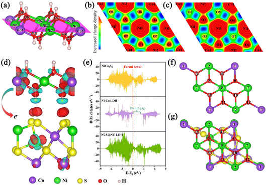
All calculations were performed using Vienna Ab initio Simulation Package (VASP v.5.4.4) software. The Perdew–Burke–Ernzerhof functional was adopted to describe the exchange–correlation energy.33 The ion–electron interaction was described by the projector augmented-wave method.34 The van der Waals interaction of the heterojunction was corrected by the DFT-D3 method. The heterojunction was constructed using Ni–Co LDH and NiCo2S4 with a size of 1 × 1 × 1 and 1 × 1 × 2. A plane wave cutoff energy of 500 eV and a 4 × 4 × 1 K-point mesh were used in the structural optimization process. A 15 Å vacuum layer was applied along the z direction. The maximum force and energy change convergence criteria were 0.03 eV Å−1 and 1 × 10⁻⁵ eV. To describe the correlation of the 3d electrons of Ni and Co, the DFT+U method was employed. According to the reported literature, the U values of Ni and Co were set to 3.8 eV and 4 eV.35,36 More detailed calculation information can be found in the descriptions of Fig. S1 and S2 (ESI†).3. Results and discussion
The schematic diagram in Fig. 1(a) shows the synthetic route of the NCS@NC LDH electrode. In the first growth stage, Ni–Co precursor nanotubes grew homogenously and vertically on Ni foam (Fig. 1(b) and (c)). At the same time, the silvery white Ni foam transformed into pink (the photographs of the as-prepared samples are provided in Fig. S3a–d, ESI†). In the second hydrothermal stage, the Ni–Co precursor was sulfurized to form NiCo2S4 nanotubes, and the color changed from pink to black (Fig. 1(d)). Compared with the Ni–Co precursor, the surface of NiCo2S4 nanotubes was rougher (Fig. S3e and f, ESI†), which might be more favorable for the attached-growth of Ni–Co LDH nanosheet. Finally, Ni–Co LDH nanosheets homogeneously covered the NiCo2S4 nanotubes, leading to the change of the color from black to jasper (Fig. 1(e) and Fig. S3g, ESI†). In addition, the XRD patterns of the samples at each step were also evaluated, which preliminarily confirmed that the designed NCS@NC LDH composite was successfully synthesized (the detailed discussions are provided in Fig. S4, ESI†).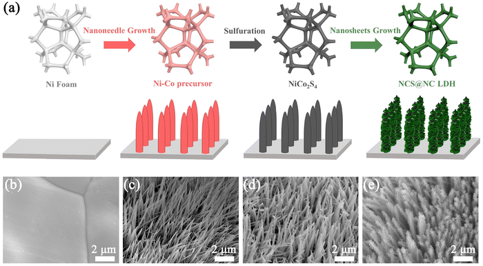 | ||
| Fig. 1 (a) Schematic diagram of the synthetic route of the NCS@NC LDH core–shell heterostructure nanoarray. SEM images of (b) Ni foam, (c) Ni–Co precursor, (d) NiCo2S4 and (e) NCS@NC LDH. | ||
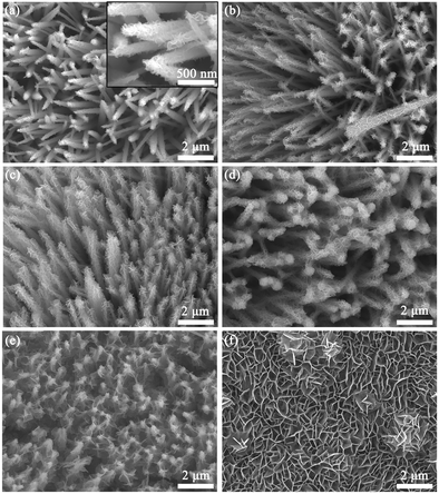
Fig. 2 displays the comparison of the SEM images of NCS@Ni–Co LDH samples with different Ni–Co LDH growth times. Fig. 2(a) and the inset show the SEM images of the 0.5 h sample. It is obvious that the NiCo2S4 nanotubes were covered by a layer of small nanosheets. As the growth time increased to 1 h, the nanosheets became obviously larger but were still sparse (Fig. 2(b)). With further increase of the growth time (2 h), the nanotubes were covered by more nanosheets, which made the nanotubes look stout (Fig. 2(c)). Fig. 2(d) shows the SEM image of the 3 h sample. Due to the overgrowth of nanosheets, the tops of some nanotubes are cross-linked to each other, which destroys the original nanoarray structure. As for the 4 h sample, the cross-linking phenomenon is more serious (Fig. 2(e)). The tops of the nanotubes are almost completely encapsulated by the nanosheets, which is not conducive to the deep penetration of the electrolyte. For comparison, Ni–Co LDH nanosheets with 2 h growth time were directly grown on Ni foam, which were cross-linked with each other (Fig. 2(f)). Such a dense structure may not be conducive to the deep permeation of the electrolyte.
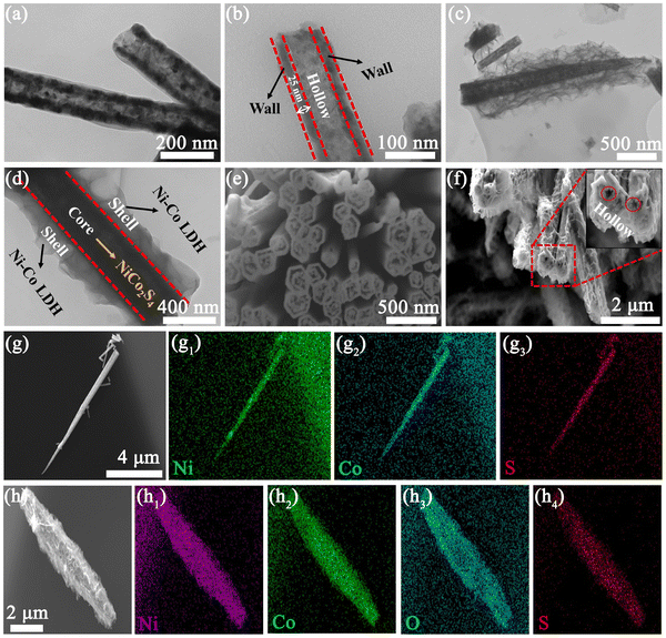
To understand the microstructures of these samples, TEM characterization was performed. As shown in Fig. 3(a), NiCo2S4 nanotubes show obvious black and white interfaces, indicating that they have a hollow structure. The walls and hollow parts of the nanotubes are marked in Fig. 3(b), where the wall thickness is ∼25 nm. Fig. 3(c), (d) and Fig. S5 (ESI†) show the TEM images of NCS@NC LDH, which display a distinct core–shell structure with a thin layer of wrinkled Ni–Co LDH nanosheets covered on NiCo2S4 nanotubes. This open structure can improve the surface area and promote the penetration of the electrolyte from the outer shell to the inner core.3,37 To further confirm the hollow structure, we used FIB to cut nanotubes. Fig. 3(e) shows the cross-section of a bundle of NiCo2S4 nanotubes, which directly demonstrates that the NiCo2S4 nanotubes are hollow. Fig. 3(f) and the inset show the cross-section of NCS@NC LDH, from which it can be seen that the core can still keep the hollow structure after growing the Ni–Co LDH shell. As we know, the fast redox reactions of pseudocapacitive materials mainly occur at the surface or near the surface,32 so the hollow structure will be beneficial for ion storage and charge transfer. Fig. 3(g)–(g3) show the SEM image and EDS mapping of NiCo2S4 nanotubes, from which it can be observed that they are mainly made up of Ni, Co and S elements. Fig. 3(h) shows the SEM image of NCS@NC LDH. Its EDS mapping shows that it mainly contains Ni, Co, O and S elements (Fig. 3(h1)–(h4)), which are uniformly distributed throughout the sample, indicating that the grown nanosheets contain Ni, Co and O elements. Fig. S6 (ESI†) shows the SAED pattern of the nanosheet, which confirms that it is a kind of hexagonal crystal. Combined with the characterization results of XRD, it can be observed that the grown nanosheets are Ni–Co LDH crystals, where Ni and Co are periodically mixed on the atomic scale, rather than the mixture of Co(OH)2 and Ni(OH)2. It is noteworthy that the EDS mapping shows that S element has a smaller enrichment area than the other three elements, which further confirms that NiCo2S4 hollow nanotubes act as the inner core, while Ni–Co LDH nanosheets act as the outer shell in NCS@NC LDH.
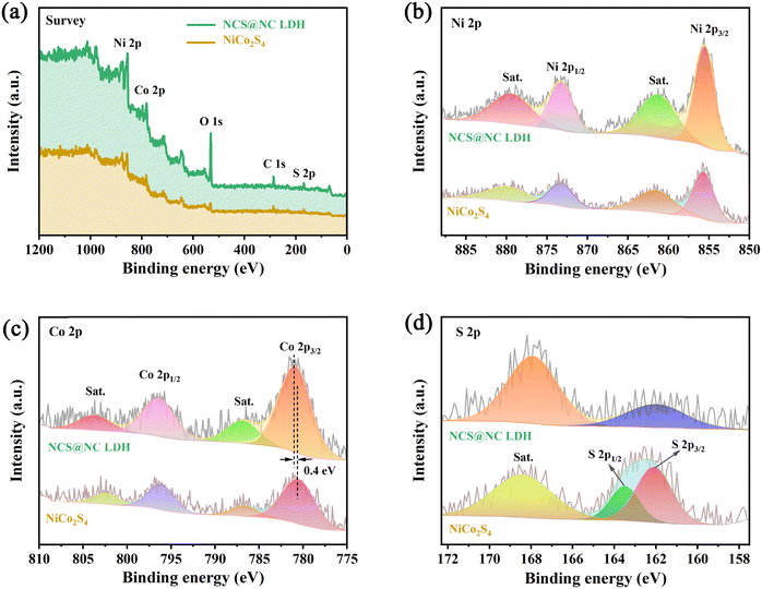
XPS characterization studies were performed to analyze the surface composition of NiCo2S4 and NCS@NC LDH. Fig. 4(a) shows that the two samples are mainly made up of Ni, Co, S and/or O, which corresponds to the EDS results. Fig. 4(b) shows the Ni 2p spectra and fitting curves. Two strong peaks of Ni 2p1/2 (873.2 eV) and Ni 2p3/2 (855.6 eV), accompanied by two weak shake-up satellite peaks (denoted as “Sat.”), show a splitting energy of about 17.6 eV, revealing the existence of Ni2+.38 The peak positions of Ni 2p in NiCo2S4 and NCS@NC LDH have no obvious difference, indicating that the valence state of Ni ions does not change when the core–shell structure is formed. The Co 2p spectra and fitting curves are provided in Fig. 4(c). The spin–orbit splitting energy of Co 2p3/2 (780.5 eV) and Co 2p1/2 (796.2 eV) in NiCo2S4 is about 15.7 eV, indicating the existence of Co3+.26,39 Compared with NiCo2S4, the Co 2p3/2 in NCS@NC LDH shifts 0.4 eV toward higher binding energy, which may be caused by the presence of Co2+ in Ni–Co LDH nanosheets or the charge transfer at the heterogenous interface. Fig. 4(d) shows the S 2p spectra, where the S 2p1/2 and S 2p3/2 of S2− in NiCo2S4 are located at 163.5 eV and 162.1 eV.40 Notably, the peak position of S 2p in NCS@NC LDH obviously shifts to lower binding energy, further verifying the existence of charge transfer at the heterogenous interface between the NiCo2S4 core and the Ni–Co LDH shell.
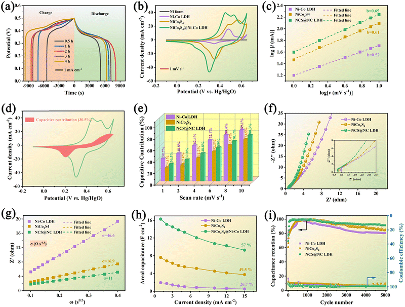
Fig. 5(a) shows the comparative GCD curves of NCS@NC LDH electrode samples at 1 mA cm−2. Upon increasing the growth time of Ni-Co LDH, the discharge time shows a trend of increase first and then decrease, which may be due to the overgrowth of Ni–Co LDH nanosheets destroying the open nanoarray structure and hindering the penetration of electrolyte (see the SEM results in Fig. 2). The 2 h electrode has the longest discharge time, suggesting that it has the highest capacity. Fig. 5(b) shows the comparative CV curves of NiCo2S4 nanotubes, Ni–Co LDH nanosheets and NCS@NC LDH (2 h) electrodes at 1 mV s−1. All curves display irregular shapes with distinct obvious redox peaks, revealing that both the NiCo2S4 core and the Ni–Co LDH shell undergo faradaic reactions during the OH− ion storage process in NCS@NC LDH. It may undergo multiple redox processes given as follows:41,42
| NiCo2S4 + 2OH− ↔ NiS4−2xOH + 2CoSxOH + 2e− | (5) |
| CoSxOH + OH− ↔ CoSx + H2O + e− | (6) |
| Ni(OH)2 + OH− ↔ NiOOH + H2O + e− | (7) |
| Co(OH)2 + OH− ↔ CoOOH + H2O + e− | (8) |
| CoOOH + OH− ↔ CoO2 + H2O + e− | (9) |
| ip = avb | (10) |
log(ip) = b![[thin space (1/6-em)]](https://www.rsc.org/images/entities/char_2009.gif) log(v) + b log(v) + b![[thin space (1/6-em)]](https://www.rsc.org/images/entities/char_2009.gif) log(a) log(a) | (11) |
 | (12) |
 are the current contributions of the surface capacitive process and the diffusion process at the corresponding scan rate, respectively. The surface capacitive contribution and diffusion contribution of NCS@NC LDH are about 30.5% and 79.5% at 1 mV s−1, respectively (Fig. 5(d)), while the surface capacitive contributions/diffusion contributions of Ni–Co LDH and NiCo2S4 are 39.7%/60.3% and 24.1%/75.9% (Fig. S9a and S10a, ESI†). With the increase of the scan rate from 1 mV s−1 to 10 mV s−1, the surface capacitive contributions of Ni–Co LDH, NiCo2S4 and NCS@NC LDH are increased to 89.1%, 73.5% and 80.3%, and the diffusion contributions are decreased to 10.9%, 26.5% and 19.7%, respectively (Fig. 5(e) and Fig. S9–S11, ESI†). These analysis results demonstrate that (i) Ni–Co LDH has large ion diffusion resistance, resulting in low diffusion contributions at high scan rates, which may be caused by its dense morphology that is not conducive to electrolyte permeation and ion intercalation; (ii) NiCo2S4 has a fast ion diffusion rate, which can be attributed to its open 3D nanoarray and hollow structure; and (iii) the designed heterostructured nanoarrays can effectively improve the ion diffusion ability of Ni–Co LDH.
Considering their large difference in the capacity, it is difficult to estimate the difference in their diffusion rate only from the capacity contribution rate. EIS is another test method that can analyze both the ion diffusion rate and electronic conductivity. Fig. 5(f) shows the Nyquist plots of the three electrodes. In the high frequency region (inset of Fig. 5(f)), Ni–Co LDH, NiCo2S4 and NCS@NC LDH electrodes show equivalent series resistances (ESRs) of 1.04 Ω, 0.84 Ω and 0.77 Ω, respectively. This result suggests that there is a fast charge transfer between the core and the shell in NCS@NC LDH during energy storage, which makes it exhibit an even lower ESR than NiCo2S4. In the low frequency range, NCS@NC LDH shows the largest slope, revealing its fast ion diffusion and low Warburg impedance (Zw). The quantitative analysis of diffusion resistance (σ) can be performed based on eqn (13):44
| Zw = σω−0.5 − jσω−0.5 | (13) |
Fig. S12 (ESI†) shows a series of GCD curves of NiCo2S4 nanotubes, Ni–Co LDH nanosheets and NCS@NC LDH (2 h) electrodes. According to these results, their specific capacitance can be calculated. Impressively, the areal specific capacitance of NCS@NC LDH reaches 16.3 F cm−2 (2010 F g−1) at 1 mA cm−2, which is approximately 2.14 times and 8.36 times that of NiCo2S4 (7.6 F cm−2, 1461.5 F g−1) and Ni–Co LDH (1.95 F cm−2, 1625 F g−1). As the current density is increased to 15 mA cm−2, their capacitances decrease gradually with different rate capabilities due to the internal diffusion resistance and charge transfer resistance. Specifically, the specific capacitances of NiCo2S4, Ni–Co LDH and NCS@NC LDH decrease to 3.76 F cm−2 (723 F g−1), 0.52 F cm−2 (433.3 F g−1) and 9.32 F cm−2 (1150.6 F g−1) with 49.5%, 26.7% and 57% retention, respectively (Fig. 5(h) and Fig. S13, ESI†). After 5000 cycles at 15 mA cm−2, the NiCo2S4 electrode and the Ni–Co LDH electrode retain 85.6% and 80.3% of their highest capacitances with coulombic efficiencies of 97.6% and 98.2%, respectively. By contrast, the capacitance retention of NCS@NC LDH is improved to 91.5% with a coulombic efficiency of 98.8%, indicating its superior cycling stability. During the initial cycling process, the capacity of the electrode shows a brief increase, which may be caused by the activation process of the electrode. Fig. S14a (ESI†) provides the GCD curves of the NCS@NC LDH electrode at the first, 110th and 5000th cycles. It can be seen that long-term charge–discharge can lead to changes in the redox potential of the electrode. Fig. S14b (ESI†) shows the SEM image of the NCS@NC LDH electrode after 5000 cycles. The electrode can still retain the core–shell nanoarray structure, but compared with the original structure, the morphology of the Ni–Co LDH nanosheets on the surface of NiCo2S4 has changed obviously, which may be the reason for the capacity fading. There are several possible reasons for this change. (i) During cycling, the lattice of Ni–Co LDH is distorted and expanded. (ii) The redox reaction process of Ni–Co LDH is not 100% reversible, and the morphology will change greatly after long-term cycling. In addition, Table S1 (ESI†) provides a comparison between the NCS@NC LDH electrode in this work and the reported core–shell structured electrode materials based on Ni–Co LDH in the past five years.19,23–25,28,45–50 Impressively, our work has exceeded a number of reported works in terms of mass loading, areal specific capacitance and cycling stability.
To better understand the mechanism of the heterostructured NCS@NC LDH in enhancing electrochemical energy storage, DFT+U calculations were performed. Fig. S15 (ESI†) shows the optimized atomic model of the NCS@NC LDH heterostructure (the detailed model construction process is shown in Fig. S1 and S2, ESI†). The interaction between NiCo2S4 and Ni–Co LDH can be described by the interfacial adhesion energy (Eadhesion), which can be calculated using the following equation:51
Eadhesion = Etotal − ENiCo2S4 − ENi–Co![[thin space (1/6-em)]](https://www.rsc.org/images/entities/char_2009.gif) LDH LDH | (14) |
Considering that in the process of storing OH−, Ni–Co LDH will undergo the process of adsorbing OH− and desorbing H, some corresponding DFT calculations were performed. Three are 12 potential adsorption sites in pure Ni–Co LDH and NCS@NC LDH, and they have been marked in Fig. 6(f) and (g). Fig. S16 and S17 (ESI†) provide optimized structural models after the adsorption of OH− at these sites. In pure Ni–Co LDH, most of the sites tend to react with OH−, and only a few sites can adsorb OH−, while NCS@NC LDH can not only react with OH−, but also have more sites to adsorb OH− on its surface, indicating that constructing heterostructured NCS@NC LDH can increase active sites for storing ions. What is more, most of the adsorption energies of NCS@NC LDH are lower than those of Ni–Co LDH, which means that NCS@NC LDH is easier to store OH− (Table S2, ESI†). Fig. S18 and Table S3 (ESI†) provide the H desorption sites and the corresponding desorption energies. Compared with pure Ni–Co LDH, a part of H in NCS@NC LDH becomes more active (the desorption energy decreases) and another part becomes more stable (the desorption energy increases). As a typical 2D battery-type electrode material, Ni–Co LDH suffers from lattice expansion and structural instability due to the OH− intercalation and faradaic reactions, resulting in poor cycling stability.32,53 Therefore, the H desorption calculations reveal that NCS@NC LDH has the advantage of improving the structural stability of Ni–Co LDH while maintaining its high reactivity.
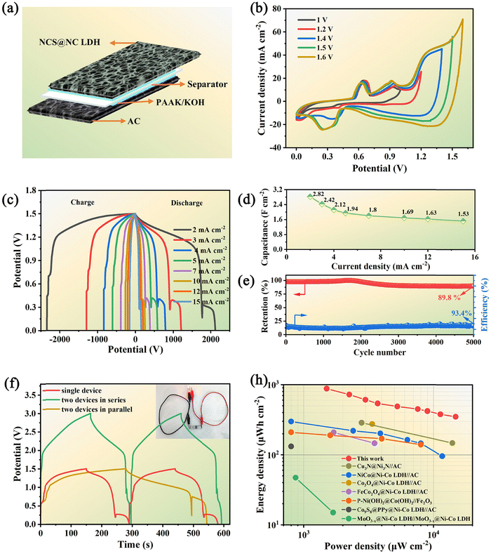
To evaluate the application potential of the designed NCS@NC LDH electrode, a kind of ASC based on the NCS@NC LDH, AC and PAAK/KOH gel electrolyte was assembled (Fig. 7(a)). Before electrochemical testing, the voltage window of the ASC device needs to be identified. Fig. 7(b) shows a series of CV curves obtained under a potential window of 1 V to 1.6 V. The result manifests that the NCS@NC LDH//AC ASC device possesses an applicable potential window of 1.5 V. The irregular CV curves with a 1.5 V potential window exhibit several distinct peaks (Fig. S19, ESI†), indicating the occurrence of the redox reactions of the NCS@NC LDH electrode during energy storage and conversion. Moreover, the similar shapes of CV curves suggest that the ASC device possesses excellent reversibility and stability. The GCD curves of the as-fabricated ASC device with obvious potential plateaus are provided in Fig. 7(c), which also reveals the excellent capacitive behaviors. According to these data, the calculated specific capacitance is provided in Fig. 7(d) and Fig. S20 (ESI†). The ASC exhibits a high capacitance of 2.82 F cm−2 (348 F g−1) at 2 mA cm−2 and still maintains 54.2% of the capacitance (1.53 F cm−2, 189 F g−1) at 15 mA cm−2. In addition, after 5000 cycles at 15 mA cm−2, it can retain 89.8% of the highest capacitance with a coulombic efficiency of 93.4%, showing outstanding cycling stability (Fig. 7(e)). Fig. S21 (ESI†) provides the GCD curves of the ASC at the first cycle and the 5000th cycle. It can be seen that, after 5000 cycles, significant changes have taken place in the reduction process in the second stage, which may be due to the structural change of Ni–Co LDH. The EIS analysis demonstrates that the ASC has small ESR (0.77 Ω) and diffusion resistance (16.4 Ω s−0.5) (Fig. S22, ESI†). Fig. 7(f) shows the comparative GCD curves of two ASCs in parallel and in series and a single ASC at 15 mA cm−2. It can be seen that the potential window of series connection and the discharge time of parallel connection are almost double those of a single ASC device, suggesting that the fabricated ASC can meet the different voltage and capacity requirements in practical applications. Moreover, the inset of Fig. 7(f) shows that two ASCs connected in series can keep a red LED light working steadily, demonstrating that it has great potential for practical application.
Fig. 7(h) shows the Ragone plot of the ASC in this work in comparison with some reported supercapacitors based on core–shell structured nanoarray electrodes. Our device shows the highest areal energy density of 880 μW h cm−2 (108.8 W h kg−1) at a power density of 1.5 mW cm−2 while still achieving 350 μW h cm−2 (59 W h kg−1) at 14.8 mW cm−2. Impressively, this energy density exceeds the values reported in a lot of previous works,19,23,47,50,54–56 such as NiCo@Ni–Co LDH//AC (298.6 μW h cm−2),54 Cu3N@Ni3N//AC (287.2 μ W h cm−2),55 Co3O4@Ni–Co LDH//AC (275.5 μW h cm−2),49etc. This result can be attributed to the following advantages of the designed NCS@NC LDH: (i) the porous and wrinkled Ni–Co LDH nanosheet shell and open array structure are beneficial for ion diffusion; (ii) the heterogeneous interface formed by Ni–Co LDH and NiCo2S4 can induce spontaneous and rapid charge transfer from the shell to the core, while improving the adsorption ability of OH−; (iii) both Ni–Co LDH nanosheets and NiCo2S4 nanotubes can contribute a large capacity; (iv) the electrode has high mass loading, resulting in an enhancement of areal specific capacitance.
4. Conclusions
In summary, a kind of heterostructured nickel–cobalt sulfide@hydroxide electrode with fast interfacial charge transfer has been prepared by means of a three-step hydrothermal process. The designed NCS@NC LDH electrode possesses a high mass loading (over 8.1 mg cm−2), outstanding areal specific capacitance (16.3 F cm−2 at 1 mA cm−2) and superior cycling stability (91.5% retention after 5000 cycles). In addition, the assembled NCS@NC LDH//AC ASC device also delivers excellent electrochemical performance, including a wide potential window (1.5 V), high areal specific capacitance (2.82 F cm−2 at 2 mA cm−2), long lifetime (89.8% retention after 5000 cycles) and remarkable areal energy density (880 μW h cm−2 at 1.5 mW cm−2). These achievements can be attributed to the judicious design of a heterostructured nickel–cobalt sulfide@hydroxide nanoarray, which can improve the charge transfer, ion diffusion and ion storage capability of the electrode. In a word, this work puts forward a promising strategy for achieving high-energy-density supercapacitors via the design of the electrode interface.Conflicts of interest
There are no conflicts of interest to declare.Acknowledgements
This work was financially supported by the National Natural Science Foundation of China (Grant no. 60171009 and U21A20500).References
- X. Peng, L. Peng, C. Wu and Y. Xie, Chem. Soc. Rev., 2014, 43, 3303–3323 RSC.
- N. Lewis, Science, 2007, 315, 798–801 CrossRef CAS.
- F. Zhu, W. Liu, Y. Liu and W. Shi, Chem. Eng. J., 2020, 383, 123150 CrossRef CAS.
- P. Huang, C. Lethien, S. Pinaud, K. Brousse, R. Laloo, V. Turq, M. Respaud, A. Demoriere, B. Chaudret and Y. Gogotsi, Science, 2010, 351, 691–695 CrossRef.
- W. Zhou, K. Yu, D. Wang, J. Chu, J. Li, L. Zhao, C. Ding, Y. Du, X. Jia and H. Wang, Nanotechnology, 2016, 27, 235402 CrossRef PubMed.
- P. Simon and Y. Gogotsi, Nat. Mater., 2008, 7, 845–854 CrossRef CAS PubMed.
- M. Hu, H. Zhang, T. Hu, B. Fan, X. Wang and Z. Li, Chem. Soc. Rev., 2020, 49, 6666–6693 RSC.
- Y. Zhang, T. Zeng, D. Huang, W. Yan and Y. Zhang, ACS Appl. Energy Mater., 2020, 3, 10685–10694 CrossRef CAS.
- C. Wu, X. Lu, L. Peng, K. Xu, X. Peng, J. Huang, G. Yu and Y. Xie, Nat. Commun., 2013, 4, 2431 CrossRef PubMed.
- Y. Liu, X. Teng, Y. Mi and Z. Chen, J. Mater. Chem. A, 2017, 5, 24407–24415 RSC.
- Z. Zhou, J. Tie, H. Yang, C. Gao, M. Sun and L. Yu, J. Mater. Sci.: Mater. Electron., 2021, 32, 3843–3853 CrossRef CAS.
- J. Zou, D. Xie, J. Xu, X. Song, X. Zeng, H. Wang and F. Zhao, Appl. Surf. Sci., 2022, 571, 151322 CrossRef CAS.
- C. Lu, A. Li, T. Zhai, C. Niu, H. Duan, L. Guo and W. Zhou, Energy Storage Mater., 2020, 26, 472–482 CrossRef.
- M. Huang, Y. Wang, J. Chen, D. He, J. He and Y. Wang, Electrochim. Acta, 2021, 381, 138289 CrossRef CAS.
- X. Bai, Q. Liu, H. Zhang, J. Liu, Z. Li, X. Jing, Y. Yuan, L. Liu and J. Wang, Electrochim. Acta, 2016, 215, 492–499 CrossRef CAS.
- H. Chen, L. Hu, M. Chen, Y. Yan and L. Wu, Adv. Funct. Mater., 2014, 24, 934–942 CrossRef CAS.
- S. Sekhar, G. Nagaraju and J. Yu, Nano Energy, 2017, 36, 58–67 CrossRef CAS.
- J. Ji, L. Zhang, H. Ji, Y. Li, X. Zhao, X. Bai, X. Fan and F. Zhang, ACS Nano, 2013, 7, 6237–6243 CrossRef CAS PubMed.
- X. He, R. Li, J. Liu, Q. Liu, R. Chen, D. Song and J. Wang, Chem. Eng. J., 2018, 334, 1573–1583 CrossRef CAS.
- J. Huang, J. Wei, Y. Xiao, Y. Xu, Y. Xiao, Y. Wang, L. Tan, K. Yuan and Y. Chen, ACS Nano, 2018, 12, 3030–3041 CrossRef CAS PubMed.
- G. Saeed, S. Kumar, P. Bandyopadhyay, N. Kim and J. Lee, Chem. Eng. J., 2019, 369, 705–715 CrossRef CAS.
- X. Li, J. Shen, W. Sun, X. Hong, R. Wang, X. Zhao and X. Yan, J. Mater. Chem. A, 2015, 3, 13244–13253 RSC.
- L. Wang, S. Li, F. Huang, X. Yu, M. Liu and H. Zhang, J. Power Sources, 2019, 439, 227103 CrossRef CAS.
- X. Gao, Y. Zhao, K. Dai, J. Wang, B. Zhang and X. Shen, Chem. Eng. J., 2020, 384, 123373 CrossRef CAS.
- H. Kuang, H. Zhang, X. Liu, Y. Chen, W. Zhang, H. Chen and Q. Ling, Carbon, 2022, 190, 57–67 CrossRef CAS.
- Y. Liu, N. Fu, G. Zhang, M. Xu, W. Lu, L. Zhou and H. Huang, Adv. Funct. Mater., 2017, 27, 1605307 CrossRef.
- Z. Ma, L. Fan, F. Jing, J. Zhao, Z. Liu, Q. Li, J. Li and Y. Fan, ACS Appl. Energy Mater., 2021, 4, 3983–3992 CrossRef CAS.
- Y. Guo, X. Hong, Y. Wang, Q. Li, J. Meng, R. Dai, X. Liu, L. He and L. Mai, Adv. Funct. Mater., 2019, 29, 1809004 CrossRef.
- J. Wu, X. Huang and X. Xia, J. Energy Chem., 2019, 35, 132–137 CrossRef.
- Y. Li, L. Cao, L. Qiao, M. Zhou, Y. Yang, P. Xiao and Y. Zhang, J. Mater. Chem. A, 2014, 2, 6540–6548 RSC.
- S. Wang, W. Jiang, L. Fei, X. Yang, Z. Huang, H. Deng, X. Zhang, H. Gu and Y. Hu, Electrochim. Acta, 2022, 423, 140547 CrossRef CAS.
- L. Luo, B. He, W. Kong and Z. Wang, Adv. Sci., 2017, 705, 349–355 CAS.
- J. Perdew, K. Burke and M. Ernzerhof, Phys. Rev. Lett., 1996, 77, 3865–3868 CrossRef CAS.
- P. Blochl, Phys. Rev. B: Condens. Matter Mater. Phys., 1994, 50, 17953–17979 CrossRef.
- Y. Bi, Z. Cai, D. Zhou, Y. Tian, Q. Zhang, Q. Zhang, Y. Kuang, Y. Li, X. Sun and X. Duan, J. Catal., 2018, 358, 100–107 CrossRef CAS.
- K. Fan, H. Chen, Y. Ji, H. Huang, P. Claesson, Q. Daniel, B. Philippe, H. Rensmo, F. Li, Y. Luo and L. Sun, Nat. Commun., 2016, 7, 11981 CrossRef CAS.
- C. Hu, K. Chang, M. Lin and Y. Wu, Nano Lett., 2006, 6, 2690–2695 CrossRef CAS PubMed.
- S. Wang, C. Tan, L. Fei, H. Huang, S. Zhang, H. Huang, X. Zhang, Q. Huang, Y. Hu and H. Gu, Front. Chem., 2020, 8, 602322 CrossRef CAS PubMed.
- M. Yan, Y. Yao, J. Wen, L. Long, M. Kong, G. Zhang, X. Liao, G. Yin and Z. Huang, ACS Appl. Mater. Interfaces, 2016, 8, 24525–24535 CrossRef CAS.
- Y. Wang, H. Wang, S. Yang, Y. Yue and S. Bian, ACS Appl. Mater. Interfaces, 2019, 11, 30384–30390 CrossRef CAS.
- H. Chen, J. Jiang, L. Zhang, D. Xia, Y. Zhao, D. Guo, T. Qi and H. Wan, J. Power Sources, 2014, 254, 249–257 CrossRef CAS.
- X. Bai, Q. Liu, H. Zhang, J. Liu, Z. Li, X. Jing, Y. Yuan, L. Liu and J. Wang, Electrochim. Acta, 2016, 215, 492–499 CrossRef CAS.
- S. Yan, S. Luo, Q. Wang, Y. Zhang and X. Liu, Composites, Part B, 2021, 224, 109246 CrossRef CAS.
- X. Zhang, G. Ma, L. Shui, G. Zhou and X. Wang, ACS Appl. Mater. Interfaces, 2021, 13, 4419–4428 CrossRef CAS PubMed.
- P. Naveenkumar and G. Kalaignan, Composites, Part B, 2019, 173, 106864 CrossRef CAS.
- J. Acharya, T. Ko, M. Seo, M. Khil, H. Kim and B. Kim, ACS Appl. Energy Mater., 2020, 3, 7383–7396 CrossRef CAS.
- J. Zhou, Q. Li, C. Chen, Y. Li, K. Tao and L. Han, Chem. Eng. J., 2018, 350, 551–558 CrossRef CAS.
- Y. Zhao, X. He, R. Chen, Q. Liu, J. Liu, J. Yu, J. Li, H. Zhang and H. Dong, Chem. Eng. J., 2018, 352, 29–38 CrossRef CAS.
- M. Shi, M. Zhao, L. Jiao, Z. Su, M. Li and X. Song, J. Power Sources, 2021, 509, 230333 CrossRef CAS.
- H. Zhang, Y. Lv, X. Wu, J. Guo and D. Jia, Chem. Eng. J., 2022, 431, 133233 CrossRef CAS.
- J. Liu, J. Wang, B. Zhang, Y. Ruan, L. Lv, X. Ji, K. Xu, L. Miao and J. Jiang, ACS Appl. Mater. Interfaces, 2017, 9, 15364–15372 CrossRef CAS.
- J. Heremans, B. Wiendlocha and A. Chamoire, Energy Environ. Sci., 2012, 5, 5510–5530 RSC.
- X. Wang, J. Li, Y. Liu, M. Wang and H. Cui, Nanoscale, 2020, 12, 23799–23808 RSC.
- W. Su, F. Wu, L. Fang, J. Hu, L. Liu, T. Guan, X. Long, H. Luo and M. Zhou, J. Alloys Compd., 2019, 799, 15–25 CrossRef CAS.
- P. Shinde, S. Park, N. Chodankar, S. Park, Y. Han, A. Olabi and S. Jun, Appl. Mater. Today, 2021, 22, 100951 CrossRef.
- K. Li, B. Zhao, J. Bai, H. Ma, Z. Fang, X. Zhu and Y. Sun, Small, 2020, 16, 2001974 CrossRef CAS.
Footnote |
| † Electronic supplementary information (ESI) available. See DOI: https://doi.org/10.1039/d2ya00183g |
| This journal is © The Royal Society of Chemistry 2022 |

