Heterostructured hybrids of metal–organic frameworks (MOFs) and covalent–organic frameworks (COFs)
Chuanpan
Guo
,
Fenghe
Duan
,
Shuai
Zhang
,
Linghao
He
,
Minghua
Wang
,
Junli
Chen
 ,
Jianqiang
Zhang
,
Qiaojuan
Jia
,
Zhihong
Zhang
,
Jianqiang
Zhang
,
Qiaojuan
Jia
,
Zhihong
Zhang
 * and
Miao
Du
 *
*
College of Material and Chemical Engineering, Zhengzhou University of Light Industry, Zhengzhou 450001, P. R. China. E-mail: 2006025@zzuli.edu.cn; dumiao@zzuli.edu.cn
First published on 15th December 2021
Abstract
Metal–organic frameworks (MOFs) and covalent–organic frameworks (COFs) with highly ordered crystalline structures show numerous advantages such as large surface areas, structural tunability, well-defined accessible pores, and thermo/chemical stability. Thus, combining different types of MOFs and COFs into one system can generate abundant MOF/COF-based hybrid nanomaterials with superior performances. In comparison to single MOFs or COFs, MOF/COF heterostructures show fantastic properties due to the synergistic effects of their different components. Accordingly, in recent years, MOF/COF-based heterostructures have received increasing attention and rapid advancements, exhibiting a broad range of potential applications in gas sorption and separation, catalysis, energy transfer, biomedicine, etc. Herein, the design principles, assembly mechanisms, synthetic approaches, and applications of different MOF/COF-based hybrids are summarized in detail. The current challenges and future perspectives for MOF/COF-based hybrids are also discussed. This review can provide deep insights into MOF/COF-based heterostructures, which will be helpful for the further development of these hybrid materials with advanced applications.
1. Introduction
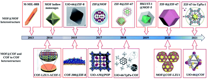
Reticular chemistry focuses on the development of framework materials prepared by linking molecular building units via coordination or covalent bonding.1–3 Highly ordered crystalline metal–organic frameworks (MOFs)1 and covalent–organic frameworks (COFs)2 have attracted interest due to their structural features and advantageous properties, such as large specific surface area, programmable structures, tunable pore size, and readily available building blocks.4 Their applications have been explored in various fields, including gas adsorption or separation, electrocatalysis, photocatalysis, energy storage, ion batteries, biosensors, and controlled delivery.5–8 Further, MOFs/COFs have unique features of tunable pore size and periodic pores, which allow the incorporation of heteroatoms/metal coordinating moieties in a periodic way. However, some challenges still exist including their synthesis and functionalization, development of new nanostructures, and application in industry.9 For example, the instability of MOFs cannot meet the industry requirement of long lifetime of commercial products. Also, their commercialization requires their large-scale production with uniform properties, and the development of simple and green synthetic methods is a current challenge to achieve their mass production at a lower cost. Alternatively, COFs are rapidly expanding porous crystalline polymers that are constructed from organic building blocks via reversible covalent bonds and have gained increasing attention from scientists.10 Two-dimensional (2D) or 3D COFs consisting of accessible nanoscale channels or pores with uniform size and tunability have been widely prepared.11 Their channel structures and pore walls provide a well-defined nanospace as reaction centers, thus leading to vast applications, such as in photocatalysis,10,12 bioimaging and therapy,13 electrochemical energy storage and conversion,14 and electrocatalysis.15However, although great efforts have been focused on the preparation, nanostructure formation, and wide applications of MOFs and COFs, individually they cannot meet the specific demand in various fields due to their intrinsic features. For example, pristine MOFs show intrinsic deficiencies such as unsatisfactory stability and limited electrical conductivity and functionality.16 Moreover, although COFs show enhanced chemical stability, their specific surface areas and degree of crystallinity are poor.10 Therefore, the hybridization of MOFs and COFs has been intensively studied to obtain superior performances (Fig. 1). For instance, the good photoconductivity and/or fast charge transfer features of COFs can remedy poor conductivity of MOFs or can promote the separation ability of photogenerated electrons and holes in MOF/COF-based hybrids. Consequently, the photoelectrochemical and electrochemical properties are improved, and thus MOF@COF hybrids can be employed for the construction of sensors to detect various targets. Moreover, the photocatalytic efficiency of MOF/COF-based hybrids also can be greatly enhanced, broadening their applications in the field of photocatalysis. Besides, MOF/COF hybrids possess an enhanced surface area and large pore volume due to the formation of quasi-micro-scaled pores at the interface between MOFs and COFs,17,18 thus manifesting enhanced hydrogen uptake capacity in the field of energy storage. By integrating different functionalized MOF and COFs, various fantastic properties are generated due to the synergistic effects of each component for extensive applications in diverse fields. For instance, MOFs with large specific surface areas can serve as carriers for loading drugs, photosensitizers, and near infrared dyes, while some COFs with strong photothermal conversion or efficient reactive oxygen species can be explored as photothermal therapy (PTT) and photodynamic therapy (PDT) agents. These hybrids possess the merits of each component, showing synergistic effects such as chemotherapy, PTT, PDT, and imaging ability. Thereby, different types of MOF- and COF-hybrids19–23 have also been developed to further widen their potential applications in gas storage and separation, catalysis, batteries, and biomedicine and biosensing.
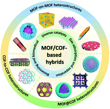
According to the nanostructures and components, diverse MOF/COF-based heterostructures have been manufactured, including MOF-on-MOF (core–shell or layered structure), MOF@COF, and COF-to-COF (or COF@COF). This review outlines the recent advances on MOF/COF-based hybrids, including the classification, design principles, synthetic approaches, and applications of different MOF/COF-based hybrids (Fig. 2). Although there are many reviews on the design principles and methods for the synthesis of MOFs and COFs, the heterostructures of MOFs/COFs have rarely been explored. Haldar et al.24 reviewed the hierarchical assemblies of MOF-on-MOF heterostructures, in which the layer-by-layer (LBL) and liquid-phase epitaxy (LPE) approaches for the preparation of surface-anchored MOF thin films and one-pot synthesis methods for these hierarchically designed structures, as well as their applications were discussed. In addition, Liu's group discussed the current advancements on the combination of MOFs and COFs,25 in which only MOF@COF composites, ranging from their synthesis to enhanced applications, were provided. Zhang et al. also reviewed crystalline porous materials for electrochemical energy storage application, which summarized several hybridization techniques according to the dimensionality of hybridization.26 Recently, a similar review was reported by Chen et al., which focused on the synthetic approaches for MOF/COF hybrids and their applications.16 Herein, a comprehensive overview of the nanostructure formation, synthesis approaches, and diverse applications of these hybrids is provided with particular focus on the following aspects: (1) the classification of MOF- and COF-related hybrids with specific nanostructures (Section 2), (2) the design principles and approaches for the synthesis of MOF- and COF-related hybrids (Section 3), (3) the detailed applications and functions of MOF- and COF-based hybrids (Section 4), and (4) the present challenges and future prospects for these hybrids (Section 5). This work aims to review the development progress, state-of-the-art designs of hybrid nanostructures, synthetic strategies, and different applications of MOF- and COF-related hybrids to provide insights into the construction of MOF/COF hybrids and deep understanding in this field.
2. Heterostructures and hybrid types of MOFs/COFs
Hybridizing diverse types of MOFs/COFs is a promising strategy to manipulate their compositions and structures and precisely tune their basic properties (such as structural flexibility, ordered pores, high surface area, and chemical functionality). MOF/COF-based heterostructures and hybrids with precise heterostructures tend to efficiently provide vast possibilities to extend their applicability.27,28 The following discussion focuses on the construction mechanism of different types of heterostructured MOF/COF-based hybrid materials.2.1 MOF-on-MOF heterostructures
MOF-on-MOF hybrid materials are generated by introducing various organic ligands after crystal nucleation,29 which can conjugate two or more different types of MOFs into one whole MOF-on-MOF hybrid material. Generally, these hybrids include two categories of architectures, namely one MOF fully enclosed by another MOF (called core–shell MOF@MOF) and one MOF grown on another MOF surface in an isotopic/anisotropic manner (called layered MOF-on-MOF). Usually, in the notation for MOF@MOF heterostructures, that on the left is the core MOF and that on the right is the grown MOF. The introduction of different MOF crystals has been extensively applied to form different types of core–shell MOF@COF heteroepitaxial crystals, while maintaining the intrinsic features of MOF crystals.30 As early as 2009, Sakata and Kitagawa's group synthesized a core–shell MOF@MOF hybrid using the epitaxial growth approach.31 In 2015, Yamauchi's group developed core–shell ZIF-8@ZIF-67 nanohybrids through a seed-mediated growth method.32 Subsequently, great efforts have been devoted to developing diverse ZIF@ZIF heterostructures.32–34 Coordinating the lattice of the second metal building unit with that of the first MOF core is essential in the construction of MOF@MOF hybrids.35 For example, MIL (Materials of Institute Lavoisier) MOFs, ZIF (Zeolitic Imidazolate Framework), PBAs (Prussian blue analogs), and other types of nanoMOF nanostructures are usually used as the core and embedded within a second MOF layer.36 Core–shell MOF-on-MOF heterostructures can combine the superior properties of their core and shell MOFs and substantially overcome the shortcomings of single MOFs.37 Their enhanced synergistic selective performance can be designed through the lattice choice and synthetic route for application in catalysis, sorption or separation, and molecular recognition.38 Therefore, these materials often exhibit specific features that differentiate them from individual MOFs.Further, layered MOF-on-MOF structures are prepared using the initial MOF layer as a substrate, on which another MOF grows in situ. Heterostructured and layered MOF-on-MOF can be synthesized via the liquid phase epitaxial and vapor phase growth methods. In 2017, Eddaoudi's group reported a synthetic strategy to precisely control the epitaxial growth of an MOF-on-MOF film, i.e., ordered hierarchical Cu-tbo-MOF-5 on HKUST-1 structure.39 Takahashi's group presented a strategy for the macroscopic length scale precise alignment of multiple layers of MOF-on-MOF films, which were fabricated by epitaxially matching the interface. An oriented Cu(OH)2 film acted as the substrate to form the first Cu2(BPDC)2 (BPDC = biphenyl-4,4′-dicarboxylate) MOF layer via a “one-pot” approach. Then, the second Cu2(BPYDC)2 (BPYDC = 2,2′-bipyridine-5,5′-dicarboxylate) MOF was deposited via liquid-phase epitaxy.40 Simultaneously, the layered MOF-on-MOF thin film was achieved via van der Waals interactions, favoring the formation of highly oriented MOF-on-MOF thin films.41 Hence, layered MOF-on-MOF heterostructures provide a good opportunity to construct MOF films with a controllable layer thickness, good orientation and crystallinity.
MOFs with similar lattices can easily form MOF@MOF hybrids. In 2012, Oh's group developed a series of MOF@MOF heterostructures, including MIL-68@MIL-68–Br, e-MIL-88B@Ga-MIL-88, MIL-68@MIL-68–X, MIL-88B@MIL-88A, In-MIL-68@MOF-NDC, MIL-68@MIL-68–Br, and MIL-68@MIL-68–X (X = NO2 or NH2).42 With the development of synthetic approaches for MOF@MOF heterostructures, MOFs with diverse lattice crystals also can be conjugated to form hybrids such as MOF-801@Ni-MOF-74,43 HKUST-1@MOF-5, UiO-67@HKUST-1, HKUST-1@IRMOF-18, UiO-66@MIL-88B(Fe), UiO-67@MIL-88C(Fe),35 PCN-68@MOF-5, and UiO-66@ZIF-8,44 and other types of Zn-MOF-on-Zr-MOF45 and Fe-MOF-on-Tb-MOF46 through the MOF-on-MOF strategy.
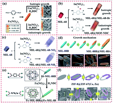 | ||
| Fig. 3 Structure of MIL-MOF-based core–shell MOF-on-MOF or layered MOF-on-MOF heterostructure. (a) Heterometalation of Fe-MIL-88B@M-MIL-88B heterostructure (core–shell-type hybrid A@B and layer-type hybrid C/A/C) using Fe-MIL-88B nanorods as the seeds. Reproduced from ref. 47 with permission from the American Chemical Society, Copyright 2012. (b) MIL-68@MIL-68–Br and MIL-68@MOF-NDC obtained by isotropic and anisotropic growth with the 3D hexagonal-structured MIL-68 as the template. Reproduced from ref. 42, with permission from the American Chemical Society, Copyright 2016. (c) MIL-68@MIL-68-X (X = NO2 or NH2) hybrid-induced growth on 3D hexagonal-structured MIL-68. Reproduced from ref. 48 with permission from the American Chemical Society, Copyright 2018. (d) Mechanism for the unbalanced MOF-on-MOF growth of MIL-88A on the MIL-88B template for the production of the lopsided core–shell of MIL-88B@MIL-88A. Reproduced from ref. 49 with permission from The Royal Society of Chemistry, Copyright 2019. (e) Tip-to-middle MOF-on-MOF growth of the core–shell hybrids of single-shelled Fe-MIL-88B@Fe-MIL-88C and double-shelled Fe-MIL-88B@Ga-MIL-88B@Fe-MIL-88C. Reproduced from ref. 50 with permission from the American Chemical Society, Copyright 2020. (f) Formation of ZIF-8@ZIF-67(Co, Zn) rings using the MOF-on-MOF method via three preparation steps, including growth of 3D ZIF on a ZIF-L surface, partially etching the 2D ZIF-L template, and transforming the 2D ZIF-L into a 3D ZIF. Reproduced from ref. 51 with permission from Wiley, Copyright 2020. | ||
Moreover, Oh's group developed the MIL-88B@MIL-88A heterostructure through the unbalanced MOF-on-MOF growth method (Fig. 3d). Given their similar 3D hexagonal structure but mismatched cell parameters, the preparation of MIL-88A on MIL-88B gave rise to an atypical MIL-88B@MIL-88A with an off-centered core. Nano-sized hexagonal MIL-88B rods with a 3D hexagonal structure were synthesized, and then used as a template to grow MIL-88A and form the core–shell MIL-88B@MIL-88A hybrid.49
Based on previous work, Oh's group constructed a core–shell MOF hybrid using the isotropic or anisotropic growth approach (Fig. 3e). The MIL-88B and MIL-88C nanostructures exhibited different chemical structures and/or cell lattices on the MIL-88B surface. Ga–MIL-88B was isotopically prepared on the Fe–MIL-88B template surface and also formed a core–shell MOF hybrid. Moreover, the core–shell hybrids of single-shelled Fe–MIL-88B@Fe–MIL-88C and double-shelled Fe–MIL-88B@Ga–MIL-88B@Fe–MIL-88C were prepared via the growth of Fe–MIL-88C on the MIL-88B core. The basic characterization revealed the change in the chemical structures and component during the growth of the MOF-on-MOF hybrids, thus showing the applicability of the unique tip-to-middle anisotropic growth approach and the unprecedented self-adjustment and self-reversion of the MOF cell lattices. All these effects finally led to the formation of the core–shell MOF@MOF hybrid via anisotropic growth.50 Besides these MOF-on-MOF heterostructures, Oh's group developed novel ZIF-8@ZIF-67(Co, Zn) rings using the MOF-on-MOF method via three preparation steps, including the growth of 3D ZIF on a ZIF-L surface, partially etching the 2D ZIF-L template, and transforming the 2D ZIF-L into a 3D ZIF (Fig. 3f). The core–shell MOF@MOF rings and plates were modulated by changing the three steps.51 In 2020, an MIL-88B-on-UiO-66 hybrid phase was prepared.52 The atypical-shaped NPs were composed of eight precisely aligned 3D hexagonal rods grown on the eight faces of one octahedron. Apparently, these core–shell MIL-MOF@MIL-MOF heterostructures were prepared using two MOFs with the same lattice crystals. Thus, the exploration of the potential applications of these well-designed MOF-on-MOF hybrid materials will be promising in the near future.
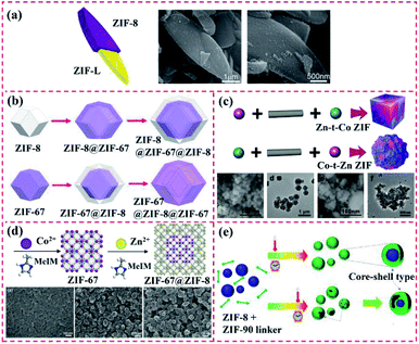 | ||
| Fig. 4 Structure of ZIF-based core–shell MOF-on-MOF hybrid. (a) Illustration and SEM images of ZIF-L@ZIF-8 core–shell nanocomposite. Reproduced from ref. 53 with permission from the American Chemical Society, Copyright 2015. (b) Synthetic scheme for the preparation of core–shell ZIF-8@ZIF-67 crystals, core–shell ZIF-8@ZIF-67@ZIF-8 crystals, core–shell ZIF-67@ZIF-8 crystals, and core–shell ZIF-67@ZIF-8@ZIF-67 crystals. Reproduced from ref. 54 with permission from the American Chemical Society, Copyright 2016. (c) Core–shell ZIF-67@ZIF-8/67 with tunable core/shell thickness. Reproduced from ref. 55 with permission from Wiley, Copyright 2017. (d) Synthesis of nanosized core–shell ZIF-67@ZIF-8 crystals via seed-mediated growth and their loading in polyimide and Pebax 1657 for gas separation. Reproduced from ref. 56 with permission from Wiley, Copyright 2020. (e) Schematic mechanism for the synthesis of ZIF-8@ZIF-90 via solvent-assisted linker exchange. Reproduced from ref. 57 with permission from the American Chemical Society, Copyright 2017. | ||
It is difficult to precisely control the synthesis of MOFs with different ligands and morphological structures are owing to their high surface energy. These types of MOF@MOF heterostructures are usually synthesized via surfactant-mediated overgrowth to reduce their surface energy. Zhuang et al. synthesized uniform and solid UiO-66@ZIF-8 particles with diverse crystalline structures and chemical components with the aid of a surfactant called cetyltrimethylammonium bromide (CTAB). A similar Pd–UiO–NH2@ZIF-8 hybrid was also synthesized and used as a catalyst, where UiO-66–NH2 NPs were applied as the core MOF to load Pd NPs and ZIF-8. Consequently, the Pd–UiO–NH2@ZIF-8 hybrid demonstrated remarkable molecular sieving behaviour.44 Song et al. developed the ZIF-8@UiO-66–NH2 hybrid using UiO-66–NH2 and ZIF-8 as the core and shell, respectively, for boosting transport pathways and molecular sieving properties. The ZIF-8 layer was synthesized over the external UiO-66–NH2 surface via the LBL solution deposition method and the UiO-66–NH2 core was sequentially added to the preparation system of ZIF-8 (Fig. 5a). During LBL processing, the amino group of UiO-66–NH2 enabled it to be covalently bonded with other MOF and ZIF precursors.58 Furthermore, Zhang et al. reported the preparation of a core–shell NH2–MIL-101(Al)@ZIF-8 nanoflower via the internally extended growth method in the presence of polyvinyl pyrrolidone (PVP) (Fig. 5b). NH2–MIL-101(Al) nanospheres were used as the core, while ZIF-8 was utilized as the shell.59 According to the above-mentioned examples, PVP with a long-chain can endow different MOFs with the ability of uniform growth by reducing their surface energy.60 For instance, Xiong et al. prepared two types of UiO-66–NH2@ZIF-8-20 and ZIF-8/UiO-66–NH2 heterostructures by using PVP as a regulator, where ZIF-8 changed from a dodecahedron to a lamellar direction growth (Fig. 5c).36
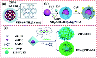 | ||
| Fig. 5 Structure of the heterostructures of hybrids of ZIFs with other types of MOFs. (a) ZIF-8@UiO-66–NH2 hybrid using UiO-66–NH2 and ZIF-8 as the core and shell. Reproduced from ref. 58, with permission from the American Chemical Society, Copyright 2017. (b) Schematic illustration of the fabrication of core–shell NH2–MIL-101(Al)@ZIF-8 nanoflower for the simultaneous detection and removal of Cu(II). Reproduced from ref. 59 with permission from The Royal Society of Chemistry, Copyright 2018. (c) Illustration of the preparation of U6N@ZIF-8 and ZIF-8/U6N. Reproduced from ref. 36 with permission from Elsevier, Copyright 2020. | ||
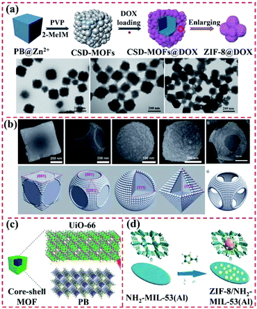 | ||
| Fig. 6 Structure of PBA-based MOF@MOF heterostructures. (a) Schematic illustration of procedure for the synthesis of PB@ZIF-8. Reproduced from ref. 62 with permission from Ivyspring International Publisher, Copyright 2017. (b) Fe3+-modulated shape control of PBA@PBA. Reproduced from ref. 63 with permission from The Royal Society of Chemistry, Copyright 2018. (c) PB as the core for the growth of a porphyrin-doped UiO-66 MOF. Reproduced from ref. 64 with permission from the American Chemical Society, Copyright 2020. (d) ZIF-8/NH2–MIL-53(Al) obtained by anchoring ZIF-8 on 2D NH2–MIL-53(Al) nanoplates. Reproduced from ref. 65 with permission from Elsevier, Copyright 2019. | ||
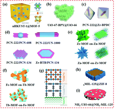 | ||
| Fig. 7 Structure of MOF-on-MOF heterostructures. (a) nHKUST-1 ⊂ MOF-5 structure formed by embedding nanocrystalline HKUST-1 (nHKUST-1) in MOF-5 crystals. Reproduced from ref. 66 with permission from the American Chemical Society, Copyright 2015. (b) Core–shell UiO-67–BPY@UiO-66. Reproduced from ref. 67 with permission from Elsevier, Copyright 2019. (c) Core–shell MOFs (PCN-222@Zr-BPDC) with mismatching lattices by epitaxial growth. Reproduced from ref. 30 with permission from the American Chemical Society, Copyright 2018. (d) Selective epitaxial growth of PCN-222 nanorods on 0D PCN-608 nanoparticle, 1D UN-1000 nanorod, and 2D PCN-134 nanoplate. Reproduced from ref. 68 with permission from the American Chemical Society, Copyright 2020. (e) Two MOF-on-MOF of Zn-MOF-on-Zr-MOF and Zr-MOF-on-Zn-MOF hybrids. Reproduced from ref. 45 with permission from Elsevier, Copyright 2018. (f) Bimetallic core–shell Tb-MOF-on-Fe-MOF and Fe-MOF-on-Tb-MOF nanostructures formed by Tb-MOF nanorod and hexagon-structured Fe-MOF. Reproduced from ref. 46 with permission from Elsevier, Copyright 2019. (g) Multiple layered MOF-on-MOF films using liquid-phase epitaxy. Reproduced from ref. 40 with permission from Wiley, Copyright 2019. (h) Selective growth of ZIF-8 on the side {110} facets of bMIL-125. Reproduced from ref. 69 with permission from The Royal Society of Chemistry, Copyright 2020. (i) NH2–UiO-66(Zr)@NH2–MIL-125(Ti) nanohybrid. Reproduced from ref. 70 with permission from Wiley, Copyright 2017. | ||
In addition to the development of core–shell MOF@MOF heterostructures, other types of MOF-on-MOF nanohybrids have been developed using various methods. In our previous work, two types of ZnZr-based MOFs, namely, Zn-MOF-on-Zr-MOF and Zr-MOF-on-Zn-MOF heterostructures, were developed via the MOF-on-MOF method by varying the addition sequence of the precursors and organic ligands (Fig. 7e). The obtained Zn-MOF-on-Zr-MOF hybrid exhibited a hierarchical decussated foliate, while the Zr-MOF-on-Zn-MOF hybrid showed a multilayered structure.45 Two core–shell Tb-MOF-on-Fe-MOF and Fe-MOF-on-Tb-MOF nanostructures were also synthesized, displaying different nanostructures from their parent MOFs (Fig. 7f).46 KenIkigaki et al. provided an oriented MOF film using a one-pot method, followed by combining two different MOF layers with epitaxial-matched lattices using the LBL approach (Fig. 7g). Precisely oriented Cu2(BPYDC)2 films were prepared as the upper MOF layer. The incorporated bipyridine linker in the oriented MOF lattice produced metal salts and ions.40 Xu's group developed a TCPP-on-Cu–HHTP (HHTP = 2,3,6,7,10,11-hexahydrotriphenylene) thin film via van der Waal forces.41 Liu et al. designed and developed MOF-on-MOF heterostructures using a site-specific epitaxial-growth strategy. For this system, two tetragonal MIL-125(Ti)-based MOF nanostructures with cake- and box-like morphologies (named cMIL-125 and bMIL-125, respectively) were used as the templates, and ZIF-8 was explored as the guest (Fig. 7h).69 Gu et al. systematically developed a novel NH2–UiO-66(Zr)@NH2–MIL-125(Ti) nanohybrid, which overcame the restriction of matching lattices for the two MOFs (Fig. 7i). With the help of PVP, NH2–MIL-125(Ti) and NH2–UiO-66(Zr) were integrated into an MOF-on-MOF nanohybrid and showed distinct morphologies and crystal structures.70
2.2 MOF@COF heterostructures
Although many individual MOFs and COFs have been synthesized and applied in diverse fields, their exploration and applications are less than satisfactory due to the limited types and monotonous structures. The MOF/COF-based hybrids obtained by combining different types of MOFs and COFs can produce multifunctional porous MOF@COF heterostructures.71 To date, the growth of MOF@COF nanohybrids mainly depends on the formation of an imine bond (–C![[double bond, length as m-dash]](https://www.rsc.org/images/entities/char_e001.gif) N–) between the reserved –NH2 groups of MOFs and aldehydes present on COFs via a condensation reaction.72 In particular, UiO-MOFs and MIL-MOFs are often employed for the fabrication of MOF@COF heterostructures because of their good chemical stability, flexible synthetic strategies, multifunctional properties, and good crystallization.73 Moreover, COF nanospheres can also serve as the core, and MOF layers synthesized around them via covalent bonds to obtain core–shell MOF@COF heterostructures.74 In this part, the current MOF@COF nanohybrids are summarized according to their MOF type.
N–) between the reserved –NH2 groups of MOFs and aldehydes present on COFs via a condensation reaction.72 In particular, UiO-MOFs and MIL-MOFs are often employed for the fabrication of MOF@COF heterostructures because of their good chemical stability, flexible synthetic strategies, multifunctional properties, and good crystallization.73 Moreover, COF nanospheres can also serve as the core, and MOF layers synthesized around them via covalent bonds to obtain core–shell MOF@COF heterostructures.74 In this part, the current MOF@COF nanohybrids are summarized according to their MOF type.
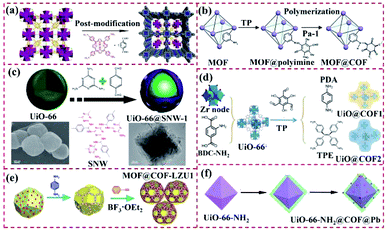 | ||
| Fig. 8 Structure of UiO-based MOF@COF heterostructures. (a) Reproduced from ref. 77 with permission from the American Chemical Society, Copyright 2017. (b) Reproduced from ref. 78 with permission from Elsevier, Copyright 2018. (c) Reproduced from ref. 79 with permission from the American Chemical Society, Copyright 2018. (d) Reproduced from ref. 80 with permission from the American Chemical Society, Copyright 2020. (e) Reproduced from ref. 72 with permission from Wiley, Copyright 2020. (f) Reproduced from ref. 84 with permission from the American Chemical Society, Copyright 2020. | ||
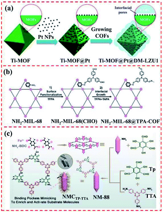
For MOF@COF hybrids, their MOF component can efficiently modulate their quality, surface morphology, optical performance, and catalytic properties. The N heteroatoms in COFs endow them high ability for binding Pd or Pt species.83 Zhu et al. provided a new UiO-66–NH2@COF@Pd hybrid using UiO-66–NH2 as the core and the covalently linked COF as the shell. Here, Pd nanoclusters (∼0.8 nm) were successfully confined in UiO-66–NH2@COF. The obtained UiO-66–NH2@COF@Pd had high porosity, good stability and large specific surface area (Fig. 8f). The prepared UiO-66–NH2@COF@Pd hybrid had a hierarchical porous structure and was loaded with abundant Pd nanoclusters. The strong synergism of each component of the hybrid led to excellent catalytic performances.84
![[double bond, length as m-dash]](https://www.rsc.org/images/entities/char_e001.gif) O groups then reacted with tetra-(4-anilyl)-methane to produce a uniform COF-300 layer. Subsequently, hydrogen bonds were formed between terephthalic acid and the amine groups on COF-300, thus boosting the integration of the ZIF-8 top layer.93
O groups then reacted with tetra-(4-anilyl)-methane to produce a uniform COF-300 layer. Subsequently, hydrogen bonds were formed between terephthalic acid and the amine groups on COF-300, thus boosting the integration of the ZIF-8 top layer.93
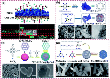 | ||
| Fig. 10 Structure of other types of MOF@COF. (a) Reproduced from ref. 93 with permission from the American Chemical Society, Copyright 2016. (b) Reproduced from ref. 94 with permission from Elsevier, Copyright 2018. (c) Reproduced from ref. 71 with permission from The Royal Society of Chemistry, Copyright 2019. (d) Reproduced from ref. 95 with permission from Elsevier, Copyright 2018. | ||
In addition to hydrogen bonds, the coordination binding between the zinc cation and amine group can enhance the binding of the COF and MOF components. In our previous work, a Co-MOF was synthesized over a terephthalonitrile-derived nitrogen-rich network surface, thus leading to the formation of the Co-MOF@TPN-COF hybrid. Co(NO3)2·6H2O and 2-methylimidazole were used to prepare Co-MOF, and terephthalonitrile was polymerized over the Co-MOF surface (Fig. 10b). The proposed Co-MOF@TPN-COF displayed the advantages of MOFs and COFs, such as abundant nitrogen-related groups and excellent conductivity.94 Gao and co-workers constructed core–shell PCN-222-Co@TpPa-1 hybrid materials via strong π–π stacking to overcome their disadvantages and produce a synergistic effect, which afforded multifunctional properties (Fig. 10c). The obtained core–shell PCN-222-Co@TpPa-1 exhibited good stability and superior catalytic activity.71 Moreover, the Ce-MOF@MCA nanohybrid was synthesized via the COF-on-MOF strategy, where MCA was prepared by reacting melamine and cyanuric acid (Fig. 10d).95
2.3 COF-to-COF heterostructures
Imine-, azine-, hydrazone- and enamine-linked COF frameworks can be combined with other types of COFs and MOFs and serve as sieving membranes. Although COF membranes have been investigated, continuous progress on this area is highly restricted. In 2018, Fan et al. constructed a bilayer COF-to-COF membrane, which was prepared by synthesizing a 2D-COF layer over the another type of 2D-COF layer. The 2D-COFs of imine-linked COF-LZU1 and azine-linked ACOF-1 were used as building blocks due to their hexagonal pore structure.96 Ying et al. developed cationic TpEBr and anionic TpPa-SO3Na nanosheets, where the two building blocks with opposite charges were assembled to form an ultrathin membrane architecture. Consequently, different effects were integrated, forming ultrathin compact layers.973. Design principles and synthetic approaches
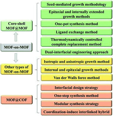
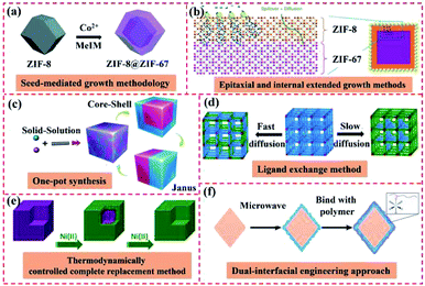
High surface energy is often generated at the interfaces between different MOFs or COFs because of their various morphologies.98 Hence, suitable methods to prepare core–shell MOF-on-MOF and other types of MOFs- or COFs-based heterostructures must be explored (Fig. 11). Among the diverse preparation methods, seed-mediated growth, epitaxial and internally extended growth, and ligand exchange are usually used for the synthesis of core–shell MOF-on-MOF heterostructures. Anisotropic growth and induced growth, internal and epitaxial growth, and template methods are also applied for the development of other types of MOF-on-MOF heterostructures. The interfacial design strategy, one-step synthesis method, and in situ polymerization approaches have been explored for MOF@COF hybrids. Temperature-swing solvothermal synthesis and LBL assembly methods are appropriate for the construction of COF-to-COF hybrids. This work provides the design principles and reviews the synthetic approaches that correspond to the classifications of MOF/COF-based hybrids with different nanostructures and morphologies.3.1 MOF-on-MOF heterostructures
Owing to the well-defined and modulated heterocompositions and heterostructures of MOF-on-MOF nanohybrids, they have been explored as efficient platforms to overcome the inherent shortcomings in basic performances of their components (e.g., poor chemical stability, structural stability, and crystallinity) and realize desirable and applicable properties (e.g., reactivity, functionality, and thermodynamic stability).42,99 Growing a secondary MOF shell on an MOF core can efficiently form complex heterostructures that protect the inner MOF cores and afford functional domains of the MOF shell in MOF hybrid materials. Different strategies for the fabrication of core–shell MOF@MOF heterostructures have been developed, such as seed-mediated growth, one-pot synthesis, epitaxial and internally extended growth, ligand exchange, and surfactant-mediated overgrowth. As an alternative method, the synthesis method of MOF-on-MOF hybrids shows potential in constructing well-defined MOF hybrids with a heterogeneous interface between two different MOFs. Generally, two MOFs with lattice matching of their cell parameters are often used for the preparation of core–shell MOF-on-MOF hybrids by growing the second MOF using the isotropic growth method. Furthermore, MOF-on-MOF hybrid materials are obtained by anisotropically growing the second MOF on the template MOF with mismatched cell parameters. These methods for the synthesis of MOF-on-MOF hybrids will be discussed in the following sections.3.1.1.1 Seed-mediated growth methodology. During the seed-induced growth procedure, the introduction of seed crystals in the starting preparation system of MOFs can accelerate their crystallization rate significantly. However, the traditional seed-induced growth approach for the preparation of core–shell MOF@MOF hybrids often has shortcomings, such as the possible nucleation of the shell MOF in solution and seed aggregation,37 thus leading to structural incompleteness and reduction in the desired performances for the hybrids. In 2015, Yamauchi's group prepared core–shell ZIF-8@ZIF-67 hybrids using the seed-mediated growth method, in which ZIF MOFs were synthesized via the coordination reaction between diverse metal clusters and imidazole-related ligands. ZIF-8 crystals were explored as the core, while ZIF-67 was used as the shell. ZIF-8 seeds with a uniform size of approximately 50 nm were prepared via the coordination of Zn2+ ions and 2-methyl-1H-imidazole (MeIm) using PVP as the capping agent. Co2+ ions were then adsorbed on the ZIF-8 seed via coordination binding with the MeIm units, which were exposed on the surface. The ZIF-67 shell grew continuously over the ZIF-8 surface. The thickness of the ZIF-67 layer increased with an increase in the ratio of Co2+/Zn2+.100–102 A series of mixed matrix membranes of the core–shell ZIF-67@ZIF-8 (ref. 56) and ZIF-L@ZIF-67 (ref. 103) has also been obtained using a similar method. Many reports focused on the core–shell ZIF-8@ZIF-67 hybrids,100–102,104 ZIF-67@ZIF-8 (ref. 56 and 105) and other types of core–shell MOF@MOF18,106 were obtained via the seed-mediated growth methodology (Fig. 12a). For these core–shell MOF@MOF heterostructures, ZIF-based crystals are often used as the seeds, whereas similar lattice ZIF networks are explored as the core. However, the preparation steps for the seed-mediated growth methodology are complicated, the production yield is low, the seeds tend to agglomerate, and pollution is generated by the residue from seed synthesis. Furthermore, lattice matching of the two MOF components is usually needed for the preparation of the core–shell MOF@MOF hybrids to ensure the alignment of the building units of the MOF core and MOF shell. Thus, these disadvantages greatly limit the construction of core–shell MOF hybrid materials using this method, hampering their extensive applications.
 | ||
| Fig. 12 Schematic illustration of the synthesis of core–shell MOF@MOF nanohybrids. (a) Reproduced from ref. 104 with permission from The Royal Society of Chemistry, Copyright 2017. (b) Reproduced from ref. 107, with permission from Springer, copyright 2018. (c) Reproduced from ref. 55 with permission from Wiley, Copyright 2017. (d) Reproduced from ref. 111 with permission from the American Chemical Society, Copyright 2017. (e) Reproduced from ref. 113 with permission from the American Chemical Society, Copyright 2012. (f) Reproduced from ref. 43 with permission from the American Chemical Society, Copyright 2020. | ||
3.1.1.2 Epitaxial and internally extended growth. Core–shell MOF@MOF hybrids with the same ligand length and topological structure are usually easily integrated, where the second MOF shell can be grown over the MOF core surface via the internally extended growth method. For example, core–shell structured ZIF-8@ZIF-67 and ZIF-67@ZIF-8, and other Matryoshka-type (ZIFs@)n−1ZIFs (e.g., tri-, tetra-, penta-, hexa-,hepta- and octa-layered ZIFs) were obtained by stepwise (batch-wise) liquid-phase epitaxial growth (Fig. 12b). The ZIF cubes were firstly prepared as the core crystals, and then added to a fresh solution containing metal ions, linkers, and CTAB surfactant, resulting in heterogeneous nucleation on the ZIF core via vertically epitaxial growth owing to the matched lattice parameters.107
For the core–shell MOF@MOF hybrid materials prepared using two MOFs with different ligands and morphological structures, it is difficult to precisely control the regular epitaxial growth owing to their high surface energy. These types of MOF@MOF heterostructures are usually synthesized via surfactant-mediated overgrowth. Surfactants, such as CTAB and PVP, can efficiently modulate the formation of MOF@MOF heterostructures by lowing their surface energy.44 Therefore, the conformation and orientation of MOFs on solid surfaces can be sustained by using cationic surfactant capping agents despite their minimal structural similarity. Tsung's group developed even UiO-66@ZIF-8 heterostructures. As is known, ZIF-8 and UiO-66 have distinct chemical structures and morphologies. Zn clusters and imidazolate were found in the ZIF-8 crystals and Zr6O4(OH)4 clusters and dicarboxylate linkers were present in UiO-66. With assistance from CTAB, homogeneous ZIF-8 outer layers were generated on homogeneously distributed UiO-66 crystals, thus forming the UiO-66@ZIF-8 hybrid.44 A core–shell NH2–MIL-101(Al)@ZIF-8 nanoflower was also prepared via an internal extended growth mode under PVP regulation. PVP molecules with long-chains were aligned along the [001] plane direction because of the high surface density of Cu(II). The efficient capping of PVP in the [001] plane greatly improved the formation of ZIF-8 from polyhedra to nanosheets by lowering its surface energy.59 Moreover, diverse core–shell or striped hetero Ln-MOF crystals have been synthesized via the anisotropic epitaxial growth method. Monometallic LIFM-18/19(Eu) crystals were prepared using TMPBPO and Eu nitrate through a simple diffusion method, followed by immersion in an acetone/water mixture solution (v/v = 3/1) containing saturated Tb(NO3)3·3H2O and TMPBPO. The second layer was propagated around the original core crystal due to the slow diffusion of acetone, thus forming a bimetallic hierarchical Eu@Tb-MOF hybrid.108
In addition to the use of surfactants, oriented hierarchical MOF heterostructures can also be constructed by dedicatedly choosing MOF seeds with similar ligands as the second MOF to match the crystal lattice. This leads to the epitaxial growth of the second MOF over the MOF seed with a small lattice mismatch. As shown in Fig. 13, three different 0D PCN-608 NPs and 1D NU-1000 nanorods, and 2D PCN-134 nanoplates were applied as templates for epitaxially growing PCN-222 nanorods. Depending on the size, shapes, and dimensionalities of these MOF cores, three different types of MOF heterostructures were achieved owing to the lattice mismatch between PCN-222 and the MOF seeds by selective epitaxial growth.68
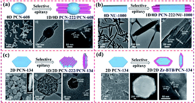 | ||
| Fig. 13 Scheme of the synthesis of (a) 1D/0D PCN-222/PCN-608, (b) 1D/1D PCN-222/NU-1000, (c) 1D/2D PCN-222/PCN-134 and (d) 2D/2D Zr-BTB/PCN-134 heterostructures. Reproduced from ref. 68 with permission from the American Chemical Society, Copyright 2020. | ||
3.1.1.3 One-pot synthesis. Among the different preparation approaches, one-pot synthesis is the most convenient to combine the multiple functionalities and performances of each component in a single platform, and thus is often applied to prepare MOF@MOF heterostructures.63 The core–shell MOF@MOF hybrids with structural integrity constructed via the one-pot synthesis method109 can remarkably avoid the possibility of producing a new surface and reduce the requirements of incipient surface energy. As shown in Fig. 12c, Guo et al. proposed the prototypical bimetallic ZIF-8/ZIF-67 heterostructures within a single MOF crystal due to distinct reaction kinetics, leading to partial distribution of different metals during the formation of the MOF.55 Similar sizes of metal ions readily were adapted to blend in the same porous framework. Uniform distributions of the two metals in the ZIF-8/ZIF-67 heterostructures were obtained at a high Co/Zn ratio of Co2+ and Zn2+ ions in the initial solution. The ZIF-8/ZIF-67 heterostructures were observed at a low Co/Zn ratio concentration gradient from Co-rich cores to Zn-rich shells. When Co2+ was added initially, the core–shell ZIF-67@ZIF-8/67 hybrids were produced, and their core/shell thickness was modulated by the reaction time interval. In contrast, when Zn2+ was introduced initially, only irregular aggregates were produced because of the low nucleation capability of Zn2+.
In addition to the ZIF-8/ZIF-67 heterostructures obtained from MOFs with the same morphology and similar sizes, core–shell MOF@MOF nanostructures have also been obtained via the one-pot synthesis method using MOFs with diverse crystal lattices. Zhou's group developed the PCN-222@Zr-BPDC hybrid via one-pot synthesis. The individual components of PCN-222@Zr-BPDC displayed mismatching lattices. The strong binding interaction between TCPP and metal cations resulted in fast homogeneous nucleation. By contrast, BPDC with low connectivity often took longer for the preparation of crystals than TCPP under similar conditions. However, heterogeneous nucleation occurred faster than its homogenous counterpart because the seed crystal was used as a core for growing the second MOF.30 Besides the ZIF@ZIF and PCN@UiO core–shell structures, monodisperse MOF@MOF comprised of two PBAs was also prepared via the one-pot synthesis strategy.63
3.1.1.4 Ligand exchange. The post-synthesis ligand exchange method (PSE) exhibits some intrinsic advantages, such as operational simplicity, widespread generality, and thus extensive applications.110 PSE is typically performed by incubating MOF crystals in a solution containing another pure ligand in the presence of a suitable solvent (DMF or water). Two possible structures of the core–shell and uniformly distributed MOF@MOF heterostructures can be constructed using this technique. A homogeneous and mixed organic building blocks was achieved, in which ligand diffusion in the MOF was faster than its exchange. When the diffusion in the MOF was slow or if the exchange was faster at the edges of the crystal, the core–shell MOF@MOF nanohybrid was obtained (Fig. 12d).111 Moreover, the core–shell ZIF-67@Co-MOF-74 hybrid was constructed by exchanging the ligands on the ZIF-67 surface with 2,5-dihydroxyterephthalic acid (DHTP) molecules. During the preparation of this nanohybrid, DHTP molecules showed higher coordination ability than 2-MeIm. When adding ZIF-67, DHTP molecules competed with 2-MeIm on the surface of ZIF-67 to coordinate with cobalt, thus generating Co-MOF-74 on ZIF-67. Finally, a ZIF-67@Co-MOF-74 core–shell structure was achieved.112
3.1.1.5 Thermodynamically controlled complete replacement. Lah's group reported a series of highly porous isostructural MOF heterostructures through the thermodynamically controlled complete replacement method, which was achieved by soaking the thermodynamically more stable MOF seeds as the core in a metal ion solution in the presence of ligands with a potentially less stable framework (Fig. 12e). This new type of MOF heterostructures demonstrated uniformly transmetalated framework structures, illustrating the boosted framework stabilities. The core–shell heterostructures were selectively transmetalated by kinetically controlling the replacement of the framework metal ions with the second MOF grown on the external MOF shell.113
3.1.1.6 Dual-interfacial engineering approach. Interfacial compatibility in mixed-matrix membranes can be realized via a dual-interfacial approach for the fabrication of MOF@MOF hybrids.114Fig. 12f shows that the ultrathin MOF-74 layer was grown on the MOF core via the dual-interfacial engineering method. This layer was comprised two interfaces of MOF–MOF and MOF-polymer. Between them, the interface at the two MOFs, MOF–MOF, was formed due to the lattice matching between the two MOFs and was strongly integrated by the coordination bonds between the metal and ligand because of the chemical similarity of the two MOFs.43 Apparently, among the methods for constructing diverse MOF@MOF hybrids, the seed-mediated growth methodology is feasible for the preparation of MOF@MOF heterostructures with a matched lattice, such as ZIF-based hybrids. Meanwhile, the epitaxial and internally extended growth methods are helpful for the development of MOF@MOF hybrids using various MOFs. In addition, the presence of a surfactant can lower the surface energy at the interface between two MOFs, thereby facilitating the formation of MOF@MOF hybrids from diverse ligands.
3.1.2.1 Isotropic and anisotropic growth. Presently, several types of MOF-on-MOF nanohybrids, including In–MIL-88B-on-Fe–MIL-88, MIL-68@MIL-68–Br, MIL-68@MIL-68–X (X = NO2 or NH2), MIL-88B@MIL-88A, Fe–MIL-88B@Fe–MIL-88C, and double-shelled Fe–MIL-88B@Ga–MIL-88B@Fe–MIL-88C, have been fabricated using isotropic or anisotropic growth and induced growth (Fig. 14a). Thus far, different MOF-on-MOF hybrid heteroparticles have been obtained by precisely modulating the isotropic and/or anisotropic nanoscale growth of various MOFs. Fe–MIL-88B, Ga–MIL-88B, and In–MIL-88B have been used for the heterometalation of MOF hybrids via the isotropic and anisotropic growth methods. Fe–MIL-88B nanorods with a hexagonal 3D structure were first prepared and explored as seeds for growing the secondary MOFs. The MOF-on-MOF heterostructure was obtained by hybridizing Fe–MIL-88B and M–MIL-88B (M = Ga or In).47 MIL-68–Br and MOF-NDC (NDC stands for naphthalene-1,4-dicarboxylic acid) were isotropically and anisotropically grown on a microMIL-68. The isotropic growth of MIL-68–Br on the MIL-68 template led to the production of the core–shell-type MIL-68@MIL-68–Br.42 The atypical lopsided core–shell of MIL-88B@MIL-88A has also been constructed via the unbalanced growth of an MOF-on-MOF hybrid. Although MIL-88A and MIL-88B had a large overall mismatch in their cell parameters because of the introduction of diverse organic linkers, the abnormal anisotropic MOF-on-MOF hybrid was obtained due to the analogous ab plane in the core and shell. Initially, nano-scale hexagonal MIL-88B rods were prepared, which then acted as a template to achieve the MIL-88B@MIL-88A hybrid by growing MIL-88A.49 The MOF hybrid of the MIL-88B or MIL-88C structure was similarly gained via the isotropic or anisotropic preparation method because these two MOFs possessed different components and/or cell lattices. Ga–MIL-88B was isotopically grown on the Fe–MIL-88B core, showing well-matched cell lattices and different components. Fe–MIL-88C was also grown on MIL-88B with mismatched cell lattices and diverse structures, resulting in single-shelled Fe–MIL-88B@Fe–MIL-88C and double-shelled Fe–MIL-88B@Ga–MIL-88B@Fe–MIL-88C hybrids.50 However, to date, the isotropic and anisotropic growth methods have only been used to prepare a series of MIL-based MOFs. Wide varieties of MOF@MOF heterostructures should be constructed in the near future.
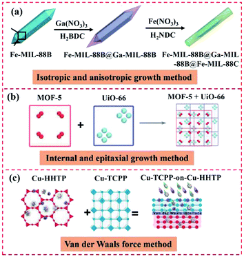 | ||
| Fig. 14 Schematic illustration of the synthesis of MOF-on-MOF heterostructures. (a) Reproduced from ref. 47 with permission from the American Chemical Society, Copyright 2020. (b) Reproduced from ref. 35 with permission from Springer, Copyright 2019. (c) Reproduced from ref. 41 with permission from Wiley, Copyright 2019. | ||
3.1.2.2 Internal and epitaxial growth. To date, only a few core–shell MOF@MOF heterostructures have been obtained via the epitaxial growth method due to the picky designs of more than two MOFs with analogous crystal structures in one nanoparticle. Gu et al. used the internally extended growth method to prepare hierarchical MOF composites and overcome the restriction of the lattice matching. NH2–UiO-66(Zr) and NH2–MIL-125(Ti) were integrated to form the MOF-on-MOF heterostructure by implementing the internally extended growth method. NH2–UiO-66(Zr) was interacted with the NH2–MIL-125(Ti) precursors with the help of PVP. Consequently, the NH2–MIL-125(Ti) nuclei were assembled with NH2–UiO-66(Zr) to produce the hybrid.70 Kim's group constructed MOF@MOF hybrids with matched interface configurations (Fig. 14b).35 The results showed a MOF-5 crystal that had grown on the {111} planes of the octahedral HKUST-1, thus forming the HKUST1@MOF-5 hybrid. Zhang's group developed a novel MIL-88B-on-UiO-66 hybrid using the heteroepitaxial growth method.52 Accordingly, coordination occurred between the linear linkers and coordinately unsaturated metal modes, giving a layer of coordinately unsaturated ligands by epitaxial growth.
3.1.2.3 van der Waals force method. As is known, van der Waals force can be freely used to combine different materials, differing from chemical bonding at the interface between two diverse materials. For instance, Cu-TCPP layers were deposited on semiconductive Cu-HHTP layers using van der Waals forces, forming oriented MOF-on-MOF thin films, which can overcome the lattice mismatching issue (Fig. 14c). Consequently, Cu-TCPP-on-Cu-HHTP thin films were obtained.41
3.2 MOF@COF heterostructures
Besides MOF-on-MOF heterostructures, integrating MOFs with COFs also can overcome the limitations of each component. A few methods have been explored for the hybridization of COFs and MOFs and showed extensive applications in diverse fields. The preparation methods of MOF@COF hybrids include interfacial design strategy, one-step synthesis method, modular synthesis strategy, and coordination-induced interlinked hybrid strategy, which will be discussed below.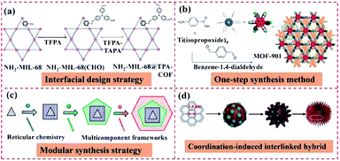 | ||
| Fig. 15 Schematic illustration of the synthesis of MOF@COF heterostructures. (a) Reproduced from ref. 74 with permission from Wiley, Copyright 2018. (b) Reproduced from ref. 116 with permission from the American Chemical Society, Copyright 2016. (c) Reproduced from ref. 117 with permission from the American Chemical Society, Copyright 2020. (d) Reproduced from ref. 118 with permission from Wiley, Copyright 2019. | ||
3.3 COF-to-COF heterostructures
Besides the methods of introducing functional groups in COFs and combining COFs with MOFs, COF-to-COF hybrids also have been developed to extend the application range of porous organic materials. To date, only two methods of temperature-swing solvothermal synthesis and LBL assembly have been applied for the development of COF-to-COF heterostructures (Fig. 16). Given that COF-LZU1 and azine-linked ACOF-1 have a similar conformation, the COF-LZU1-ACOF-1 bilayer membrane was fabricated through integration. COF-LZU1 was prepared via the reaction of 1,3,5-triformylbenzene with PDA, while ACOF-1 with high-crystallinity was synthesized by reacting TFB with hydrazine hydrate. Owing to the feasible preparation of COF-LZU1 via TFB and PDA, the COF-LZU1-ACOF-1 bilayer was easily synthesized through a facile temperature-swing solvothermal synthesis.96 Zhao's group proposed the preparation of the TpEBr@TpPa-SO3Na hybrid using two intrinsically charged ionic covalent–organic nanosheets with opposite charges and explored it as building blocks for the assembly of ultrathin membrane architectures with reduced apertures under the driving force of electrostatic attractive interaction.97 | ||
| Fig. 16 Schematic illustration of the synthesis of COF-to-COF heterostructures. Reproduced from ref. 96 with permission from Wiley, Copyright 2018. | ||
Diverse approaches can be explored for the construction of various types of MOF-on-MOF and MOF@COF heterostructures. For instance, the seed-mediated growth method is suitable for the synthesis of core–shell MOF@MOF hybrids using ligands with similar lattices. The one-pot synthesis method and epitaxially/internally extended growth method are beneficial for the preparation of MOF@MOF hybrids using different ligands. The isotropic and anisotropic growth methods are helpful for MOF-on-MOF hybrids that use ligands with a matched lattice. Furthermore, the functionality of MOFs is essential for the fabrication of MOF@COF to bind different layers into an integrated system. Choosing a suitable preparation approach is essential for the development diverse MOF/COF-based hybrids with different nanostructures. The utilization of surfactants is a feasible way to control the formation mechanism and behavior of MOF/COF hybrids.
4. Applications of MOF/COF-based heterostructures
Due to the efficient integration of different types of MOFs and COFs, the formed diverse MOF-on-MOF, MOF@COF, and COF-to-COF heterostructures often exhibit excellent crystal and structural performances, such as extended skeletons, large specific surface area, excellently electrochemical activity, and synergistic effect among their different components. Therefore, these MOF/COF-based heterostructures show practical applications in different fields, including catalysis, gas adsorption/separation, biosensing and biomedicine.4.1 Catalysis
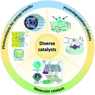
Various MOF/COF-based heterostructures have been developed as multifunctional catalysts, such as electrocatalysts, photocatalysts, photodegradation catalysts for pollutants and heavy metal ions, and molecular catalysts. According to their application field, these MOF/COF-based heterostructures are mainly classified into three categories, including photocatalysts for energy transfer, photodegradation catalysts, and molecular catalysts for organic synthesis (Fig. 17). In this section, the extensive and promising applications of these heterostructures will be highlighted and discussed.MOF@COF hybrids inherit the advantages of their parent components, and thereby have wide potential applications as photocatalysts for driving diverse reactions.115 Therefore, the good photoconductivity and/or fast charge transfer features of COFs can remedy the poor conductivity of MOFs.126 Owing to the tunable features of both MOFs and COFs, chemical interactions can occur between them,73 thus leading to some specific functionalities. This operation can avoid the removal of COF layers and result in a homogeneous integration, which can be explored as diverse photocatalysts. Lan's group provided an integrated porous NH2–UiO-66/TpPa-1-COF hybrid with superior photocatalytic H2 evolution under visible light (Fig. 18a–d). After modulation of its basic performances, the NH2–UiO-66/TpPa-1-COF (4![[thin space (1/6-em)]](https://www.rsc.org/images/entities/char_2009.gif) :
:![[thin space (1/6-em)]](https://www.rsc.org/images/entities/char_2009.gif) 6) hybrid displayed a high photocatalytic H2 evolution rate of 23.41 mmol g−1 h−1, 20-times higher than that of TpPa-1-COF. Because of its outstanding light absorbance ability, TpPa-1-COF in NH2–UiO-66/TpPa-1-COF played a light-harvesting role upon visible light irradiation. The photogenerated electrons of TpPa-1-COF transferred from the valence-band (VB) to conduction-band (CB), which then further rapidly migrated to the CB of NH2–UiO-66 via covalent bonding interaction, ensuring that the photogenerated electrons oppositely moved to holes. The efficiently separation of electrons in the CB of NH2–UiO-66 reduced H+ in the presence of a Pt co-catalyst.115 Li et al. presented the hierarchical NH2–MIL-125(Ti)/B-CTF-1 (15TBC), which displayed superior photocatalytic ability for hydrogen production, with a transfer rate over 15 wt% (15TBC) and maximum photocatalytic activity of 360 μmol h−1 g−1 under visible light irradiation (Fig. 18e–h). The good photocatalytic ability of the MOF/COF hybrids was attributed to the large amounts of amide bonds formed between B-CTF-1 and MOFs. These functional groups are essential for both the enhancement of charge separation and the improvement of photocatalysis stability. For this novel photocatalysis system, electrons and holes were generated from both NH2–MIL-125(Ti) and B-CTF-1, providing a new photocatalysis strategy based on an MOF/COF hybrid.73 Similarly, the NH2–UiO-66@TFPT–DETH nanohybrid exhibited a high hydrogen evolution rate of 7178 mmol g−1 h−1, which was 3-fold higher than that of TFPT–DETH. Electron–hole pairs were produced from both NH2–UiO-66 and TFPT–DETH under visible light illumination (Fig. 18i–l). For this system, photogenerated electrons migrated rapidly from NH2–UiO-66 CB to TFPT–DETH CB, while holes transferred in the opposite direction. The enhanced photocatalytic activity of the core–shell NH2–UiO-66@TFPT–DETH heterostructure was mainly due to the synergistic effect originated from the NH2–UiO-66@TFPT–DETH heterostructure, such as the extension of light absorption, the improvement in exaction dissolution and transfer, and high porous structures.81
6) hybrid displayed a high photocatalytic H2 evolution rate of 23.41 mmol g−1 h−1, 20-times higher than that of TpPa-1-COF. Because of its outstanding light absorbance ability, TpPa-1-COF in NH2–UiO-66/TpPa-1-COF played a light-harvesting role upon visible light irradiation. The photogenerated electrons of TpPa-1-COF transferred from the valence-band (VB) to conduction-band (CB), which then further rapidly migrated to the CB of NH2–UiO-66 via covalent bonding interaction, ensuring that the photogenerated electrons oppositely moved to holes. The efficiently separation of electrons in the CB of NH2–UiO-66 reduced H+ in the presence of a Pt co-catalyst.115 Li et al. presented the hierarchical NH2–MIL-125(Ti)/B-CTF-1 (15TBC), which displayed superior photocatalytic ability for hydrogen production, with a transfer rate over 15 wt% (15TBC) and maximum photocatalytic activity of 360 μmol h−1 g−1 under visible light irradiation (Fig. 18e–h). The good photocatalytic ability of the MOF/COF hybrids was attributed to the large amounts of amide bonds formed between B-CTF-1 and MOFs. These functional groups are essential for both the enhancement of charge separation and the improvement of photocatalysis stability. For this novel photocatalysis system, electrons and holes were generated from both NH2–MIL-125(Ti) and B-CTF-1, providing a new photocatalysis strategy based on an MOF/COF hybrid.73 Similarly, the NH2–UiO-66@TFPT–DETH nanohybrid exhibited a high hydrogen evolution rate of 7178 mmol g−1 h−1, which was 3-fold higher than that of TFPT–DETH. Electron–hole pairs were produced from both NH2–UiO-66 and TFPT–DETH under visible light illumination (Fig. 18i–l). For this system, photogenerated electrons migrated rapidly from NH2–UiO-66 CB to TFPT–DETH CB, while holes transferred in the opposite direction. The enhanced photocatalytic activity of the core–shell NH2–UiO-66@TFPT–DETH heterostructure was mainly due to the synergistic effect originated from the NH2–UiO-66@TFPT–DETH heterostructure, such as the extension of light absorption, the improvement in exaction dissolution and transfer, and high porous structures.81
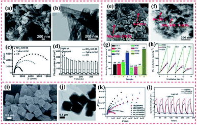 | ||
Fig. 18 (a) and (b) Scanning electron microscopy (SEM) and transmission electron microscopy (TEM) images of TpPa-1-COF and NH2–UiO-66/TpPa-1-COF (4![[thin space (1/6-em)]](https://www.rsc.org/images/entities/char_2009.gif) : :![[thin space (1/6-em)]](https://www.rsc.org/images/entities/char_2009.gif) 6). (c) Electrochemical impedance spectroscopy (EIS) Nyquist plots of NH2–UiO-66, TpPa-1-COF and NH2–UiO-66/TpPa-1-COF (4 6). (c) Electrochemical impedance spectroscopy (EIS) Nyquist plots of NH2–UiO-66, TpPa-1-COF and NH2–UiO-66/TpPa-1-COF (4![[thin space (1/6-em)]](https://www.rsc.org/images/entities/char_2009.gif) : :![[thin space (1/6-em)]](https://www.rsc.org/images/entities/char_2009.gif) 6) hybrid material. (d) Transient photocurrents measurements. Reproduced from ref. 115 with permission from Wiley, Copyright 2018. (e) SEM and (f) TEM image of 15TBC. (g) Rate of hydrogen evolution over the different samples under visible light irradiation. (h) Cycling runs of the as-prepared catalysts under visible light irradiation. Reproduced from ref. 73 with permission from Elsevier, Copyright 2019. (i) SEM and (j) TEM image of U@TDE4. (k) EIS Nyquist plots and (l) photocurrent density curves of NH2–UiO-66, TFPT–DETH and U@TDE4 in 0.1 mmol L−1 Na2SO4 solution under visible light irradiation. Reproduced from ref. 81 with permission from The Royal Society of Chemistry, Copyright 2020. 6) hybrid material. (d) Transient photocurrents measurements. Reproduced from ref. 115 with permission from Wiley, Copyright 2018. (e) SEM and (f) TEM image of 15TBC. (g) Rate of hydrogen evolution over the different samples under visible light irradiation. (h) Cycling runs of the as-prepared catalysts under visible light irradiation. Reproduced from ref. 73 with permission from Elsevier, Copyright 2019. (i) SEM and (j) TEM image of U@TDE4. (k) EIS Nyquist plots and (l) photocurrent density curves of NH2–UiO-66, TFPT–DETH and U@TDE4 in 0.1 mmol L−1 Na2SO4 solution under visible light irradiation. Reproduced from ref. 81 with permission from The Royal Society of Chemistry, Copyright 2020. | ||
Beside the exploration of photocatalysts for H2 evolution based on MOF@COF, Guo reported core–shell ZIF-67@MOF (MOF = Co-MOF-74, Co-BDC, Co–NH2BDC and Co-BTC) catalysts for driving water oxidation reaction under visible light. They revealed that the core–shell ZIF-67@Co-MOF-74 with an MOF shell of 50 nm showed the oxygen evolution production of 15 μmol after 8 min, while that of ZIF-67 and Co-MOF-74 was 9.8 and 11.8 μmol, respectively. The core–shell ZIF-67@Co-MOF-74 hybrid showed enhanced catalytic ability due to the following factors: (i) abundant crystal defects formed on the rough surface of the core–shell MOFs substantially improved the exposed metal centers and their sufficient contact; (ii) abundant-OH and –COO groups on the core–shell surface were helpful for adsorbing water molecules, leading to overall water splitting to produce oxygen; and (iii) the interface of the core–shell MOFs exhibited high conductivity, further boosting the electron transport and resulting in the separation of electrons and holes, which greatly inhibited charge recombination.112
Additionally, Lu et al. used the NH2–MIL-125@TAPB-PDA hybrid as a good photocatalyst for selectively oxidizing alcohols. The results demonstrated that the addition of an appropriate content of COF greatly facilitated the electronic and optical performances, and thus improved the photocatalytic ability distinctly. The NH2–MIL-125@TAPB-PDA-3 composite with a 20 nm-thick COF shell had the highest production (94.7%) of benzaldehyde, which was 2.5- and 15.5-times higher than that of NH2–MIL-125 and COF, respectively. The excellently photocatalytic ability of the NH2–MIL-125@TAPB-PDA-3 hybrid was ascribed to the boosted charge transfer between the two parts.127 Based on the above discussion about the photocatalytic activity of MOF@COF heterostructures, it can be deduced that combining the two components of MOFs and COFs can greatly enhance their catalytic performance.
| Materials | Contaminant | Irradiation time (min) | Initial concentration (mg L−1) | Removal% | Adsorption capacity | Ref. |
|---|---|---|---|---|---|---|
| NH2–MIL-101(Al)@ZIF-8 | Cu(II) | — | 10–250 | — | 526.74 mg g−1 | 59 |
| MIL-101@NH2–MIL-125 | Cr(VI) | 120 | 10 | 72 | — | 70 |
| Fe3O4@HKUST-1/MIL-100(Fe) | MB | 180 | 20 | >90 | — | 144 |
| MIL-125@ZIF-8 | Orange II | 120 | 50 | 97.3 | — | 69 |
| NH2–MIL-68@TPA-COF | RhB | 40 | 20 | — | — | 74 |
| NH2–MIL-125(Ti)/TTB-TTA | MO | 20 | 10 | >90 | — | 89 |
| MOF-5/COF (M5C) | AO and RhB | 8 | 5 | >90 | — | 145 |
4.1.2.1 Removal and photodegradation of heavy metal ions. Heavy metal ions (Cu(II), Cd(II), Cr(VI), and Pb(II)) in water bodies are seriously harmful to human beings. The high accumulation of heavy metal ions not only can remarkably destroy the natural ecosystem but also can lead to serious damage to human beings.143 Recently, Zhang et al. reported core–shell NH2–MIL-101(Al)@ZIF-8 nanohybrids and explored their use as an adsorbent of Cu(II) (Fig. 19a). Considering the high binding of the imidazole nitrogen in ZIF-8 with Cu(II), the proposed NH2–MIL-101(Al)@ZIF-8 hybrid exhibited a high adsorption efficiency (526.74 mg g−1) toward Cu(II). In addition, the fluorescence performance of NH2–MIL-101(Al) demonstrated a Cu(II)-dependent change, resulting in a superior selective/sensitive sensing performance in a broad linear range (1.5–625 mM), showing a low detection of limit (LOD) of 0.17 mM for Cu(II) (Fig. 19b and c).59 Additionally, it is essential to adsorb Cr(VI) from wastewater due to its high toxicity toward organisms.146 Kitagawa's group proposed a novel MIL-101(Cr)@NH2–MIL-125(Ti) heterostructure (Fig. 19d), where the synergy between the two pure MOFs was beneficial for enhancing the degradation of Cr(VI). The MIL-101(Cr)@NH2–MIL-125(Ti) exhibited an adsorption capacity for Cr(VI) of 3.16 mg g−1. Apparently, the presence of MIL-101(Cr) supplied additional mesoporous channels for boosting the adsorption of Cr(VI) in the internal microporous NH2–MIL-125(Ti) (Fig. 19e). However, Cr(VI) was not degraded by the single MIL-101(Cr). As shown in Fig. 19f, 72% of Cr(VI) was dislodged from the solution by MIL-101(Cr)@NH2–MIL-125(Ti) after 120 min under visible light irradiation, while only 47% of Cr(VI) was removed by NH2–MIL-125(Ti). It also displayed the band-gap energy of MIL-101(Cr)@NH2–MIL-125(Ti) was identical to that of the pure NH2–MIL-125(Ti).70
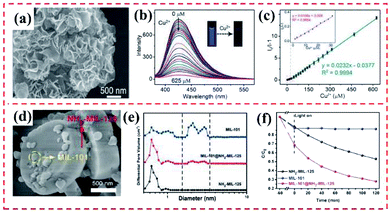 | ||
| Fig. 19 (a) SEM image of NH2–MIL-101(Al)@ZIF-8 core–shell nanoflower. (b) Fluorescence emission spectra of NH2–MIL-101(Al)@ZIF-8 suspension (0.047 mM) upon the addition of various concentrations of Cu(II) under excitation at 325 nm. (c) Corresponding Stern–Volmer linear fitting curves of NH2–MIL-101(Al)@ZIF-8 toward Cu(II) in a high concentration range. Reproduced from ref. 59 with permission from The Royal Society of Chemistry, Copyright 2018. (d) SEM image of typical MIL-101@NH2–MIL-125 heterostructured hybrid crystal. (e) Pore width distribution based on the NLDFT model of MIL-101, NH2–MIL-125, and MIL-101@NH2–MIL-125. (f) Adsorption and photocatalytic degradation toward Cr(VI) with MIL-101, NH2–MIL-125, and MIL-101@NH2–MIL-125. Reproduced from ref. 70 with permission from Wiley, Copyright 2017. | ||
4.1.2.2 Adsorption and photodegradation of organic pollutants. Organic dyes have been vastly applied in diverse industrial production fields. Also, water containing organic dyes is released to the aquatic environment, resulting in severe pollution.147 Thus, the removal and treatment procedures of organic dyes from water systems are extremely significant for protecting the environment and life.148 Chen's group reported a series of hierarchically sandwiched Fe3O4@HKUST-1/MIL-100(Fe) hybrid materials and their application as photocatalysts to degrade methylene blue (MB) under visible light (Fig. 20a). In comparison with the individual or pristine MOFs, the obtained MOF-on-MOF hybrid demonstrated a substantially improved specific surface and small interior pore size. Meanwhile, the removal efficiency of MB by Fe3O4@HKUST-1/MIL-100(Fe) hybrid was comparable with pure Fe3O4@MIL-100(Fe) but with only half the layers (Fig. 20b).144 Further, Liu et al. developed MIL-125@ZIF-8 heterostructures, where the high adsorption ability of ZIF-8 and the photocatalytic performance of MIL-125 were integrated (Fig. 20c). The developed MIL-125@ZIF-8 hybrid displayed a faster degradation rate of Orange II with a removal rate of 97.3% within 2 h under visible light irradiation, much higher than that of MIL-125 (54.6%) (Fig. 20d). The physically mixed ZIF-8/MIL-125 exhibited a much lower degradation efficiency in comparison to that of the MIL-125@ZIF-8 heterostructure, revealing the synergistic effect between MIL-125 and ZIF-8. These results verified that control over the site of ZIF-8 growth is vital for modulating the photocatalytic activity of MOF-on-MOF heterostructures.69
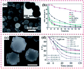 | ||
Fig. 20 (a) SEM and TEM images of the obtained Fe3O4@HKUST-1/MIL-100(Fe) (1![[thin space (1/6-em)]](https://www.rsc.org/images/entities/char_2009.gif) : :![[thin space (1/6-em)]](https://www.rsc.org/images/entities/char_2009.gif) 1) particles. (b) MB removal efficiency as a function of time with different types of hybrid materials. The shadowed area represents the experiments conducted in a dark environment. Reproduced from ref. 144 with permission from the American Chemical Society, Copyright 2019. (c) SEM images of bMIL-125@ZIF-8. (d) Degradation efficiency of ZIF-8, cMIL-125, bMIL-125, cMIL-125/ZIF-8, bMIL-125/ZIF-8, bMIL-125, cMIL-125@ZIF-8 and bMIL-125@ZIF-8. Reproduced from ref. 69 with permission from The Royal Society of Chemistry, Copyright 2020. 1) particles. (b) MB removal efficiency as a function of time with different types of hybrid materials. The shadowed area represents the experiments conducted in a dark environment. Reproduced from ref. 144 with permission from the American Chemical Society, Copyright 2019. (c) SEM images of bMIL-125@ZIF-8. (d) Degradation efficiency of ZIF-8, cMIL-125, bMIL-125, cMIL-125/ZIF-8, bMIL-125/ZIF-8, bMIL-125, cMIL-125@ZIF-8 and bMIL-125@ZIF-8. Reproduced from ref. 69 with permission from The Royal Society of Chemistry, Copyright 2020. | ||
Besides the superior catalytic ability of MOF@MOF hybrids, there are many reports on the application of MOF@COF nanohybrids for the photodegradation of different pollutants. Zhang's group prepared a core–shell NH2–MIL-68@TPA-COF hybrid material and employed it as an efficient photocatalyst for the visible-light driven degradation of rhodamine B (RhB) (Fig. 21a and b). Given that NH2–MIL-68 possesses photocatalytic activity, NH2–MIL-68@TPA-COF displayed a photocatalysis rate constant of 0.077 min−1, 1.4-times higher than that of NH2–MIL-68 (Fig. 21c and d). The detailed discussion on the basic characterization of the NH2–MIL-68@TPA-COF nanohybrid revealed that the improved photocatalytic property of NH2–MIL-68@TPA-COF was mainly ascribed to its large Brunauer–Emmett–Teller (BET) surface area and small band gap.74 Further, He et al. prepared an NH2–MIL-125(Ti)/TTB-TTA hybrid with outstanding photocatalytic activity. Specifically, NH2–MIL-53(Al), NH2–MIL-125(Ti) and NH2–UiO-66(Zr) were utilized for doping TTB-TTA for the production of heterogeneous photocatalysts (Fig. 21e–g). Considering the well-matching band gaps between NH2–MIL-125(Ti) and TTB-TTA, the obtained NH2–MIL-125(Ti)/TTB-TTA hybrid illustrated remarkably photocatalytic activity for degrading methyl orange (MO) dye and colorless phenol under visible light irradiation owing to its intrinsic features of large surface area, porous nanostructure and high crystallinity. The self-photolysis of MO was very slight under visible light exposure in the absence of NH2–MIL-125(Ti)/TTB-TTA, while the NH2–MIL-125(Ti)/TTB-TTA catalyst showed a high photodegradation capacity toward MO (Fig. 21h and i). However, the photocatalytic activity of a physical mixture of NH2–MIL-125(Ti) and TTB-TTA was inferior to that of NH2–MIL-125(Ti)/TTB-TTA. This was mainly ascribed to the prominent role of the covalent binding in the NH2–MIL-125(Ti)/TTB-TTA hybrid, which greatly enhance the transfer of photogenerated electrons.89 An MOF-5/COF (M5C) hybrid was prepared via the hybridization of a zinc-based MOF and melamine-terephthaldehyde (Fig. 21j and k) and applied as a good sorbent to quickly and efficiently remove auramine O (AO) and RhB cationic dyes from aqueous media due to its combined forces. The obtained MOF-5/COF adsorbent displayed an adsorption efficiency of 17.95 and 16.18 mg g−1 for AO and RhB dyes, respectively, at pH 9.5. The results showed that AO and RhB molecules were planar, which were easily adsorbed by the MOF-5/COF hybrid via physisorption forces besides the MOF-5/COF cavities. Also, the AO and RB dyes were encapsulated in the cavities of MOF-5/COF and bound to MOF-5/COF through electrostatic interaction, hydrogen bonding, and van der Waals forces, as well as host–guest interactions with the MOF-5/COF cavities (Fig. 21l).145
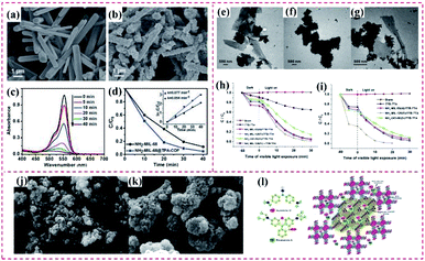 | ||
| Fig. 21 SEM image of (a) NH2–MIL-68 and (b) NH2–MIL-68@TPA-COF. (c) UV-vis absorption spectra of RhB in the presence of NH2–MIL-68@TPA-COF hybrid material upon visible light irradiation. (d) Comparison of photodegradation efficiencies of RhB in the presence of NH2–MIL-68 and NH2–MIL-68@TPA-COF. Reproduced from ref. 74 with permission from Wiley, Copyright 2018. TEM images of (e) NH2–MIL-53(Al)/TTBTTA, (f) NH2–MIL-125(Ti)/TTB-TTA and (g) NH2–UiO-66(Zr)/TTB-TTA. (h) Photocatalytic degradation of MO (10 mg L−1) over as-prepared photocatalysts under visible light irradiation. (i) Photodegradation of phenol (10 mg L−1) over TTB-TTA, NH2–MIL-53(Al)/TTB-TTA, NH2–MIL-125(Ti)/TTB-TTA, NH2–UiO-66(Zr)/TTB-TTA, and a physical mixture of NH2–MIL-125(Ti) and TTB-TTA (NH2–MIL-125(Ti) + TTB-TTA). Reproduced from ref. 89 with permission from Elsevier, Copyright 2019. (j) and (k) SEM images of M5C. (l) Interactions of the dyes with the adsorbent and proposed mechanism. Reproduced from ref. 145 with permission from the American Chemical Society, Copyright 2020. | ||
Based on the above discussion, it can be deduced that only limited MOFs or COFs can be explored as photocatalysts for degrading pollutants or adsorbing the organic dyes or heavy metal ions. MIL-101(Cr), NH2–MIL-125(Ti), NH2–MIL-125(Ti), and MIL-100(Fe) are often integrated with other types of MOFs or COFs, showing improved photocatalytic activity. Thus, to further broaden the range of degradable pollutants, it is significant to develop some novel heterostructures based MOFs or COFs.
| Catalyst | Substrate | Conversion (%) | Selectivity (%) | Time | Ref. |
|---|---|---|---|---|---|
| Pd@H–Zn/Co-ZIF | Ethylene hydrogenation | >80 | >80 | 10 h | 105 |
| PCN-222(Fe)@Zr-BPDC | Epoxidation of alkenes | >99 | — | 12 h | 30 |
| PCN-222-Co@TpPa-1 | Deacetalization-Knoevenagel condensation | 99.3 | — | 10 h | 71 |
| UiO-67-BPY@UiO-66 | Benzaldehyde | 98 | — | 1 h | 67 |
| MOF-901 | Polymerization of methyl methacrylate | 87 | — | 18 h | 116 |
| UiO-66@SNW-1 | Deacetalization-Knoevenagel condensation | 99.6 | 99.6 | 12 h | 79 |
| MIL@NTU-1 | Styrene oxidation | 32 | 84 | 12 h | 153 |
| UiO-66–NH2@COP@(2.34%)Pd | Hydrogenation of nitrobenzene | 100 | 99.9 | 30 min | 84 |
| Ti-MOF@Pt@DM-LZU1 | Hydrogenation of styrene | >99 | >99 | 40 min | 85 |
Given that epoxides are extensively applied in the production of diverse chemical raw materials and intermediates in many organic reactions, olefin epoxidation is a vital reaction.150 However, although many transition-metal catalysts have been developed for catalytic epoxidation reactions, it is difficult to separate the product from the catalyst.151 Recently, Zhou's group explored the preparation of PCN-222@Zr-BPDC hybrids with mismatching lattices, followed by their application as size-selective catalysts for olefin epoxidation, where the high porosity of the MOFs remarkably boosted the selectivity toward shape and size. In the case of the core–shell PCN-222@Zr-BPDC hybrid, the Fe-porphyrin moieties on PCN-222 served as the active centers for the epoxidation reaction toward olefin, whereas the selectivity of the substrates was dependent on the tunable shell. Olefins with different molecular sizes were transformed into the corresponding epoxides, showing different conversion ratios, where the small olefins demonstrated ideal conversions. The PCN-222@Zr-BPDC hybrid exhibited high accessibility and catalytic activity given that the size of the olefin was smaller than the pore size of Zr-BPDC (UiO-67), affording fast and efficient diffusion of the substrate. The catalytic results displayed that the olefin conversion decreased with an increase in the size of the olefins. Conversely, the decreasing trend of olefin conversion was not further observed for smaller olefins obtained under analogous preparation conditions. This revealed that olefins with large sizes were blocked by the shell, limiting the diffusion rates and hampering the accessibility of these molecules to the catalytic centers. Consequently, this catalytic system showed high size selectivity.30 Similarly, Han's group proposed the core–shell PCN-222-Co@TpPa-1, which integrated the advantages of PCN-222-Co and TpPa-1. Due to the Lewis acid active sites present in PCN-222-Co, active Brønsted base sites in TpPa-1 (imine groups), and efficient interaction between the reactants and the PCN-222-Co@TpPa-1 hybrid, the PCN-222-Co@TpPa-1 heterostructure demonstrated an efficient bifunctional catalysis performance for the one-pot cascade deacetalization–Knoevenagel condensation reaction. Two sequential steps occurred in the catalytic reaction, including the reaction of benzaldehyde dimethylacetal to benzaldehyde by catalyzing with the unsaturated Zr(IV) and Co(II) centers and production of 2-benzylidenemalononitrile via the Knoevenagel condensation reaction by catalyzing with the imine groups in TpPa-1, giving a high yield of 99.3%.71
Considering that it is difficult to separate and recover the catalyst used for Knoevenagel condensation, consequently generating a large amount of waste,152 it is vital to develop heterogeneous catalysts, which illustrate evident advantages such as less side reactions, feasible separation step, low corrosiveness and good reusability. Gong et al. reported a UiO-67–BPY@UiO-66 shell-structure. Combining the high stability of UiO-66 and active Lewis basic sites of the bipyridyl linker, the UiO-67–BPY@UiO-66 hybrid was then explored as a heterogeneous catalyst for catalyzing the Knoevenagel condensation. The outstanding catalytic efficiency was mainly attributed to the homogeneous distribution of active sites (Lewis basic) present in the external layer of the UiO-67–BPY@UiO-66 heterostructure.67
Besides MOF-on-MOF hybrids, diverse MOF@COF hybrids have also been constructed for application in heterogeneous catalysis and organic catalysis. Cordova group's developed a 2D MOF-901, involving Ti-MOF modified with benzene-1,4-dialdehyde through imine condensation reactions. The incorporation of Ti(IV) units endowed MOF-901 with efficient photocatalysis ability by coating poly(methyl methacrylate) (polyMMA), which showed a high-number-average molar mass (26![[thin space (1/6-em)]](https://www.rsc.org/images/entities/char_2009.gif) 850 g mol−1).116 Furthermore, Kim's group developed a Pd/TiATA@LZU1 composite as an excellent photocatalyst toward tandem dehydrogenation and hydrogenation reactions, where these reactions were carried out in a continuous-flow microreactor.88 Further, Wu et al. presented a UiO-66@SNW-1 photocatalyst for tandem deacetalization–Knoevenagel condensation reaction. Owing to the fact that UiO-66@SNW-1 was comprised of Lewis acid sites (Zr clusters in UiO-66) and Brønsted base sites (amino groups in SNW-1), the UiO-66@SNW-1 catalyst exhibited remarkably higher catalysis ability than that of its UiO-66, SNW-1, and UiO-66–NH2 parents. Moreover, Li's group prepared a core–shell MOF@COF composite with enhanced catalytic efficiency and fast transfer procedure. The prepared NH2–MIL-101(Fe)@NTU-COF hybrid displayed good selectivity toward benzaldehyde, indicating that the catalytic selectivity was remarkably improved by the NTU-COF shell.90 Zhu et al. constructed a UiO-66–NH2@COP@Pd heterostructure as an efficient catalyst for reducing 4-nitrophenol (4-NP) to 4-aminophenol (4-AP). The results verified that BH4− and 4-NP were adsorbed on the surface of UiO-66–NH2@COP@(2.34%)Pd via π–π stacking interaction. Afterward, the donor BH4− transferred electrons to the acceptor 4-NP, together with the reaction of BH4− with H2O, affording NaBO2 and H2. Additionally, Pd nanoclusters prompted H2 to dissociate into H–H bonds. Subsequently, the activated H atoms escaped from the Pd sites to catalyze 4-NP, further efficiently transferring to 4-AP and desorbing from the UiO-66–NH2@COP@(2.34%)Pd surface.84 As aforementioned, the NH2–MIL-125(Ti) MOF has been explored as an efficient photocatalyst for degrading pollutants and photocatalytic hydrogen evolution.154 It also has great promise for application as a molecule catalyst. Sun et al. proposed a core–shell NH2–MIL-125(Ti)@DM-LZU1 heterostructure and loaded Pt NPs. The prepared Ti-MOFs@Pt@DM-LZU hybrid was used as a photocatalyst for site-selective hydrogenation reactions. Accordingly, the Pt NPs remarkably promoted the charge separation in Ti-MOFs to produce electron-rich Pt NPs, while the reactant and diffusion around the active Pt NPs were remarkably boosted owing to the high hydrophobicity and porosity of the COF shell.85
850 g mol−1).116 Furthermore, Kim's group developed a Pd/TiATA@LZU1 composite as an excellent photocatalyst toward tandem dehydrogenation and hydrogenation reactions, where these reactions were carried out in a continuous-flow microreactor.88 Further, Wu et al. presented a UiO-66@SNW-1 photocatalyst for tandem deacetalization–Knoevenagel condensation reaction. Owing to the fact that UiO-66@SNW-1 was comprised of Lewis acid sites (Zr clusters in UiO-66) and Brønsted base sites (amino groups in SNW-1), the UiO-66@SNW-1 catalyst exhibited remarkably higher catalysis ability than that of its UiO-66, SNW-1, and UiO-66–NH2 parents. Moreover, Li's group prepared a core–shell MOF@COF composite with enhanced catalytic efficiency and fast transfer procedure. The prepared NH2–MIL-101(Fe)@NTU-COF hybrid displayed good selectivity toward benzaldehyde, indicating that the catalytic selectivity was remarkably improved by the NTU-COF shell.90 Zhu et al. constructed a UiO-66–NH2@COP@Pd heterostructure as an efficient catalyst for reducing 4-nitrophenol (4-NP) to 4-aminophenol (4-AP). The results verified that BH4− and 4-NP were adsorbed on the surface of UiO-66–NH2@COP@(2.34%)Pd via π–π stacking interaction. Afterward, the donor BH4− transferred electrons to the acceptor 4-NP, together with the reaction of BH4− with H2O, affording NaBO2 and H2. Additionally, Pd nanoclusters prompted H2 to dissociate into H–H bonds. Subsequently, the activated H atoms escaped from the Pd sites to catalyze 4-NP, further efficiently transferring to 4-AP and desorbing from the UiO-66–NH2@COP@(2.34%)Pd surface.84 As aforementioned, the NH2–MIL-125(Ti) MOF has been explored as an efficient photocatalyst for degrading pollutants and photocatalytic hydrogen evolution.154 It also has great promise for application as a molecule catalyst. Sun et al. proposed a core–shell NH2–MIL-125(Ti)@DM-LZU1 heterostructure and loaded Pt NPs. The prepared Ti-MOFs@Pt@DM-LZU hybrid was used as a photocatalyst for site-selective hydrogenation reactions. Accordingly, the Pt NPs remarkably promoted the charge separation in Ti-MOFs to produce electron-rich Pt NPs, while the reactant and diffusion around the active Pt NPs were remarkably boosted owing to the high hydrophobicity and porosity of the COF shell.85
Owing to the fact that MOF-based heterogeneous catalysts are composed of organic and inorganic segments, multiple active sites can be integrated in MOF-on-MOF and MOF@COF heterostructures for synergistic and/or cascade organic catalysis and photocatalysis. However, aiming at the improvement of the catalytic activity and selectivity, the poor acid stability of these nanomaterials, which cannot withstand harsh conditions, have to be overcome. Moreover, given that COFs have superior catalytic activity to many MOFs, further work is needed to develop much more MOF@COF heterostructures and exploit them in the field of organic catalysis.
4.2 Gas sorption and separation
As reported, MOFs and COFs have been vastly explored as excellent adsorbents for gas adsorption and separation. In this part, the applications of MOF-on-MOF and MOF@COF heterostructures in the field of gas adsorption/separation are highlighted and discussed in detail.| Materials | S BET (m2 g−1) | Adsorbate | Gas uptake (mmol g−1) | Uptake pressure (bar) | Uptake temp. (°C) | Ref. |
|---|---|---|---|---|---|---|
| a BET specific surface area. | ||||||
| MIL-101@UiO-66 | 2772 | H2 | 2.4 wt% | 1 | −196 | 18 |
| MIL-101 | 1716 | 1.9 wt% | ||||
| UiO-66 | 1186 | 1.5 wt% | ||||
| IRMOF-2@MOF-5 | 610 | H2 | 1.9 wt% | 25 | −196 | 157 |
| IRMOF-2 | 1700 | 2.78 wt% | ||||
| MOF-5 | 3340 | 5.02 wt% | ||||
| ZIF-8@ZIF-67 | 1402.15 | H2 | 2.03 wt% | 1 | −196 | 158 |
| ZIF-8 | 1323.62 | 1.43 wt% | ||||
| ZIF-67 | 1392.30 | 1.53 wt% | ||||
| nHKUST-1⊂MOF-5 | 1470 | CH4 | 197 mg g−1 | 80 | 25 | 66 |
| nHKUST-1 | — | 169 mg g−1 | ||||
| MOF-5 | — | 126 mg g−1 | ||||
| UiO-66–NH2@COF-TAPB-BTCA | 1153 | H2O | 0.39 g g−1 | 0.9 P/P0 | — | 17 |
| UiO-66–NH2 | 1151 | 0.43 g g−1 | ||||
| COF-TAPB-BTCA | 319 | 0.20 g g−1 | ||||
Ren et al. developed the MIL-101(Cr)@UiO-66(Zr) heterostructure as an efficient H2 adsorbent (Fig. 22a and b). Basic characterizations verified that the MIL-101@UiO-66 sample displayed an enhanced surface area and large pore volume, indicating the introduction of UiO-66 in the MIL-101 framework (Fig. 22c). The enhanced hydrogen uptake capacity of MIL-101@UiO-66 was higher than that of MIL-101 by 26% and that of UiO-66 by 60% (Fig. 22d).18 Additionally, the Janus IRMOF-2@MOF-5 heterostructure was proposed and developed as a hydrogen adsorbent. The hydrogen-storage capacity of the Janus particles was similar to that of a physical mixture of the two components. Janus particles seem to maintain their interconnected pore structures, making them good candidates for gas separation.157 Moreover, two types of ZIF-8@ZIF-67 and ZIF-67@ZIF-8 heterostructures were prepared. The H2 storage ability of the two core–shell ZIFs was superior to that of Co/Zn-ZIF and a physical mixture of ZIF-8 and ZIF-67 owing to their unique structures and element diversity.158 The “nHKUST-1 ⊂ MOF-5” heterostructure was developed for adsorbing fuel molecules (Fig. 22e). Differing from the pure MOF-5 or nHKUST-1 framework, the gravimetric uptake capacity of nHKUST-1 ⊂ MOF-5 for CH4 illustrated high volumetric fuel storage capacity and reversible CH4 uptake efficiency (Fig. 22f–h).66
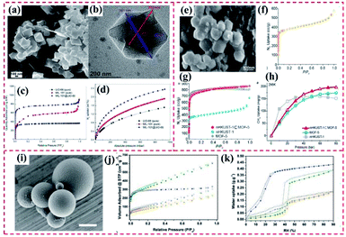 | ||
| Fig. 22 (a) SEM and (b) TEM image of the core–shell nanocrystals. (c) N2 sorption isotherms, and (d) H2 sorption isotherms for the desolated MIL-101 (pure), UiO-66 (pure) and core–shell MIL-101@UiO-66 hybrid samples. Reproduced from ref. 18 with permission from Elsevier, Copyright 2014. (e) SEM image of nHKUST-1. (f) N2 gas–adsorption isotherm of nHKUST-1. (g) N2 gas adsorption isotherms of the MOF-5, nHKUST-1, and nHKUST1 ⊂ MOF-5 samples. (h) Gravimetric adsorption uptake capacity of nHKUST-1 ⊂ MOF-5, MOF-5, and nHKUST-1 for methane. Reproduced from ref. 66 with permission from the American Chemical Society, Copyright 2015. (i) FESEM images of UiO-66–NH2@COF-TAPB-BTCA beads. (j) N2 adsorption isotherms for UiO-66–NH2 (blue), COFTAPB-BTCA beads (orange), physical mixture of these two components (grey), and UiO-66–NH2@COF-TAPB-BTCA beads (green). (k) Water adsorption isotherms for UiO-66–NH2 (blue), COF-TAPBBTCA beads (orange), physical mixture of these two components (grey), and UiO-66–NH2@COF-TAPB-BTCA (green). Reproduced from ref. 17 with permission from Wiley, Copyright 2019. | ||
Besides the exploration of adsorbents based on MOF-on-MOF nanohybrids, the MOF@COF heterostructure also demonstrates a synergistic enhancement in gas adsorption. Maspoch's group presented the UiO-66–NH2@COF-TAPB-BTCA nanohybrid (Fig. 22i). Because of its large surface area, UiO-66–NH2@COF-TAPB BTCA displayed higher adsorption ability for water at the same P/P0 than that of the pristine COF pores, displaying enhanced water uptake. The N2 and H2O adsorption isotherms of the UiO-66–NH2@COF-TAPB-BTCA cores both exhibited around 3-fold higher SBET and 2-fold higher qmax values due to the additional pores at the MOF/COF interface (Fig. 22j and k).17 Further, Wang et al. proposed an a novel COF-MOF co-assembly strategy by combining [M3(OH)1−x(O)x(COO)6]MOF-type and [B3O3(py)3]COF-type trimers. At 1 bar and 273 K, the CO2 uptake capacity was 3.96 to 6.32 mmol g−1 in tpb-pacs. The C2H2 uptake of the COF-MOF was enhanced from 5.61 to 10.45 mmol g−1, which was ascribed to tpb. This investigation demonstrated the introduction of C3-symmetric fragments present in COFs in COF–MOF structures.159 However, in comparison with the conventional MOF and COF materials, the limited types of MOF@MOF and MOF@COF hybrids restrict their applications in gas adsorption.
| Materials | Pore size (nm) | S BET (m2 g−1) | Gas separation | Capacity (mmol−1 g, 1 bar) | Selectivity | Ref. |
|---|---|---|---|---|---|---|
| a BET specific surface area. | ||||||
| MOF@COF composite | COF: 2.0 | COF: 2286.6 | H2/CO2 | 13.5 | 6.0 | 93 |
| ZIF-8: 1.18 | ZIF-8: 1869.5 | 9.1 | ||||
| MOF-S@MOF-C | — | 187.74 | CO2/N2 | 2.3 | 32.7 | 162 |
| PSF-ZIF@MOF | 0.6/0.4 | — | CO2/N2 | 2.33 | 39 | 58 |
| MOF@COF-based MMMs | — | 723 | CO2/CH4 | 93 | 46.7 | 78 |
| COF-LZU1-ACOF-1 | 0.3–0.5 | 386 | H2/CH4 | — | 15 | 96 |
| TpEBr@TpPa-SO3Na iCON | 0.4 | — | H2/CO2 | — | 26 | 97 |
| FeNi-M′ MOF | 0.4 | 383 | C2H2/CO2 | 4.29 | 24 | 163 |
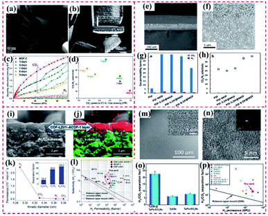 | ||
| Fig. 23 SEM image of core–shell MOF-S@MOF-C composite after (a) 4-day and (b) 6-day exchange reaction. (c) CO2 and N2 adsorption/desorption isotherms and (d) CO2/N2 selectivity and CO2 uptake (273 K, 1 bar) for MOF-S@MOF-C with 0-(MOF-C), 3-, 4-, 7-, 8- and 9-day (MOF-S) exchange. Reproduced from ref. 162 with permission from the American Chemical Society, Copyright 2019. Cross-section SEM images of PSF-5-ZIF@MOF membranes at (e) low magnification and (f) high magnification. Effect of LBL ZIF coating cycles on (g) pure gas permeability and (h) ideal gas selectivity of hybrid PSF membranes. Reproduced from ref. 58 with permission from the American Chemical Society, Copyright 2017. (i) Cross-sectional views of the supported COF-LZU1-ACOF-1 bilayer membrane. (j) EDXS mapping of the membrane cross-section and corresponding elemental distributions. (k) Single-gas performances of the COF-LZU1-ACOF-1 bilayer membrane as a function of the kinetic diameter of the permeating molecules. Mixed gas selectivity of (l) H2/CO2 as a function of H2 permeability for our two pure COF membranes and the COF–COF bilayer membrane compared with literature data. Reproduced from ref. 96 with permission from the American Chemical Society, Copyright 2018. (m) Low-magnification SEM image of TpPa-SO3Na nanosheets on α-Al2O3 support. (n) HRTEM image of TpPa-SO3Na nanosheets. (o) H2/CO2 separation factor of these membranes in separating an equal molar mixture of H2/CO2 gas. (p) Comparison of H2/CO2 separation performance with other membranes. Reproduced from ref. 97 with permission from the American Chemical Society, Copyright 2020. | ||
Considering the outstanding separation performance toward mixed gases by MOFs and COFs, combined frameworks based on MOF@COF and COF@COF have also been explored as separation membranes toward gas mixtures. For instance, Chen et al. reported UiO-66–NH2@TpPa-1 hybrids by combining the size selectivity of MOF fillers with the high stability of COF, which were explored as fillers in mixed matrix membranes (MMMs) for separating mixtures of CO2/CH4. Especially, the large pores of TpPa-1 COF efficiently prevented the blockage of the MOF pores, thus improving the gas permeation. Because of the high binding interaction between the coated COF layers and PSF, the developed UiO-66–NH2@TpPa-1-based MMM acted as a polymer and filler. Significantly, the synergism caused by the size selectivity of the MOF pores and rigid modification of the polymer chains permitted the excellent permeation of CO2 over CH4 through the obtained MMMs.78 Moreover, Fan et al. developed a COF-LZU1-ACOF-1 membrane with a suitable size range for gas molecules (Fig. 23i and j). Its separation selectivity toward gas mixtures of H2/CO2, H2/N2, and H2/CH4 outperformed that of the COF-LZU1 and ACOF-1 membranes because of its interlaced pore networks (Fig. 23k and l). Notably, the prepared membrane not only showed high permeability and selectivity but also surpassed the latest Robeson upper bounds. Its high permeability was ascribed to its thin COF-to-COF layer with a thickness of about 1 μm.96 Ying et al. proposed a TpEBr@TpPa-SO3Na iCON hybrid and employed it for the gas separation of an H2/CO2 mixture (Fig. 23m and n). The TpEBr@TpPa-SO3Na iCON hybrid demonstrated superior separation capacity, showing a high separation factor of 22.6, higher than that of the TpEBr nanosheet membrane and TpPaSO3Na membrane (Fig. 23o). Notably, the TpEBr@TpPaSO3Na iCON membrane had a good separation performance with H2 and an H2/CO2 separation factor of 22.6 (Fig. 23p). This high separation factor of the TpEBr@TpPa-SO3Na iCON was mainly ascribed to the reduced pore size caused by the staggered stacking of iCONs and the compact dense membrane structures.97
Although the extensive applications of MOFs and COFs have been investigated in the field of gas separation, their disadvantages such as high cost and poor stability in some organic solvents hinder their extensive industrial applications. Thus, rapid development and many efforts should focused on the construction of diverse MO-on-MOF, MOF@COF and COF-to-COF hybrids, which meet some requirements such as low cost, high aqueous and chemical stability, and high separation efficiency.
4.3 Biosensing and biomedical fields
Compared to traditional nanomaterials applied in the fields of biosensors and biomedicine, nano-sized MOFs exhibit the superior biological activity, high chemical and colloidal stability, efficient surface modification, and improved biological distribution. However, most MOFs and COFs suffer from a lack of multi-functional performance and unsatisfactory stability in various environments such as acidic and alkaline media or the physiological environment. Chemical stability and biocompatibility are crucial for the sensing performances and effective treatment. The stability of MOFs is governed by multiple factors, including their ligand structure, the oxidation state and the ionic radius of their metal ions, metal–ligand coordination geometry, and hydrophobicity of their pore surface. Among them, the metal–ligand bond strength is critical to obtain labile coordination bonds, further controlling the stability of MOFs in different sensing systems. Theoretically, the stability of the metal–ligand bond can be simply predicted using the hard/soft acid/base (HSAB) principle. Another concern in the biosensing and biomedical fields is biocompatibility, and therefore metal ions and ligands or monomers with low toxicity should be adopted for the synthesis of MOF/COF hybrids. To achieve the desired functions such as light harvesting, monomers with specific structures such as phthalocyanines and porphyrin are required. Diverse MOFs or COFs have been explored as platforms for biosensors or as drug delivery systems and nanocatalytic drugs. Thus, to extend the application range of these porous materials, some MOF@COF conjugations were prepared and have demonstrated promise in the biomedical field.| Material | Target | Detection method | Linear range | LOD | Ref. |
|---|---|---|---|---|---|
| a PTK7: protein tyrosine kinase 7; EIS: electrochemical impedance spectroscopy; CA125: carbohydrate antigen 125; MCF-7 cells: human breast adenocarcinoma cell; BLM: bleomycin; OTC: oxytetracycline; AMP: ampicillin; ATP: adenosine triphosphate; CT26 cells: colorectal cancer cells; DPV: differential pulse voltammetry; SWV: square wave voltammetry; HER2: human epidermal growth factor receptor 2; miRNA-21: microRNA 21; and PSA: prostate specific antigen. | |||||
| UiO-67@Ni-MOF | Glucose | Amperometric | 5–3.9 mM | 0.98 mM | 189 |
| Zn-MOF-on-Zr-MOF | PTK7 | EIS | 1 × 10⁻³ to 1 ng mL−1 | 0.84 pg mL−1 | 45 |
| Tb-MOF-on-Fe-MOF | CA125 | EIS | 0.1–200 U mL−1 | 58 μU mL−1 | 46 |
| MCF-7 cells | 1 × 10² to 1 × 10⁵ cell per mL | 19 cell per mL | |||
| AgNCs/Apt@CuFe@FeFe | BLM | EIS | 1 × 10⁻⁵ to 0.1 pg mL−1 | 0.0082 fg mL−1 | 192 |
| Ce-MOF@COF | OTC | EIS | 1 × 10⁻⁴ to 0.5 ng mL−1 | 17.4 fg mL−1 | 95 |
| Co-MOF@TPN-COF | AMP | EIS | 1 × 10⁻⁵ to 2 ng mL−1 | 0.217 fg mL−1 | 94 |
| UiO@COF | ATP | Ratiometric fluorescence | 0–10 μM | 0.067 μM | 80 |
| PO43− | 0–30 μM | 0.038 μM | |||
| Cr-MOF@CoPc | CT26 cells | EIS | 50–1 × 10⁷ cells per mL | 36 cells per mL | 193 |
| DPV | 8 cells per mL | ||||
| CDs@ZrHf-MOF | HER2 | EIS | 1 × 10⁻³ – 10 ng mL−1 | 19 fg mL−1 | 174 |
| MCF-7 cells | 1 × 10²–1 × 10⁵ cell per mL | 23 cells per mL | |||
| Pd NPs/CMC–COF–LZU1 | HeLa cells | Colorimetric | 1 × 10²–1 × 10⁶ cell per mL | 100 cells per mL | 194 |
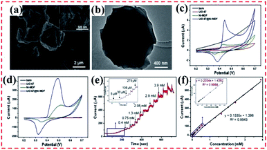 | ||
| Fig. 24 (a) SEM image and (b) TEM image of prepared UiO-67@Ni-MOF. CV curves of bare GCE, UiO-67/GCE, Ni-MOF/GCE, and UiO-67@Ni-MOF/GCE in 0.1 M NaOH in the (c) absence and (d) presence of glucose. (e) Amperometric i–t curves of UiO-67@Ni-MOF/GCE with the successive injection of glucose in 0.1 M NaOH at 0.55 V by stirring. (f) Calibration plot of current versus glucose concentrations for UiO-67@Ni-MOF/GCE, corresponding to (e). Reproduced from ref. 189 with permission from Elsevier, Copyright 2020. | ||
Considering the immobilization interaction between aptamer strands and MOF or COF networks such as π–π stacking, van der Waals force, hydrogen bonds, and possible coordination networks,190 MOFs or COFs can be employed as a sensitive layer for the development of biosensors. These biosensors can be further used to detect the corresponding targets of the aptamers or antibodies (biomarkers, antibiotics, or heavy metal ions).174 By integrating the advantages of diverse MOFs and COFs, MOF-on-MOF and MOF@COF heterostructures can lead to superior sensing performances compared to their individual components. In our previous work, we developed two novel types of scaffolds for binding the PTK7-targeted aptamer (PTK7: protein tyrosine kinase 7), followed by the detection of PTK7. The Zr-MOF component remarkably enhanced the anchoring of the aptamer, while the Zn-MOF part greatly stabilized the formed G-quadruplex of the ZnZr-based MOFs (Fig. 25a–f) developed between the aptamer strands and PTK7 because of the specific recognition (Fig. 25g and h). Compared with the Zr-MOF-on-Zn-MOF-based aptasensor, the Zn-MOF-on-Zr-MOF-based aptasensor had higher sensing ability, an ultralow detection limit of 0.84 pg mL−1 within a wide linear PTK7 concentration (Fig. 25i and j) and comprehensive excellent sensing performances. Moreover, Tb-MOF exhibited remarkable fluorescence, while both Fe-MOF and Tb-MOF displayed outstanding detection performances, excellent electrochemical activity, and good biocompatibility.45 Hence, our group synthesized two types of heterostructured bimetallic TbFe-MOF, i.e., Tb-MOF-on-Fe-MOF and Fe-MOF-on-Tb-MOF (Fig. 25k–p). After the CA125-targeted aptamer (CA125: carbohydrate antigen 125) was anchored, the obtained bimetallic MOF-based aptasensor was effectively used to sensitively determine CA125 and cancer cells. The Tb-MOF-on-Fe-MOF-based biosensor displayed higher stabilization ability toward the formed G-quadruplex than that of the Fe-MOF-on-Tb MOF-based biosensor because of the strong immobilization of aptamer over the Tb-MOF-on-Fe-MOF substrate. Hence, the fabricated biosensor showed a very low LOD for analyzing CA125 and cancer cells (Fig. 25q–t) owing to its superior biocompatibility and good endocytosis.46
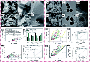 | ||
| Fig. 25 (a) SEM, (b) TEM and (c) HR-TEM images of Zn-MOF-on-Zr-MOF. (d) SEM, (e) TEM and (f) HR-TEM images of Zr-MOF-on-Zn-MOF hybrids. (g) EIS Nyquist plots of Zn-MOF-on-Zr-MOF-modified Au electrode for the detection of 0.001 ng mL−1 PTK7. (h) Variation in the charge-transfer resistance (Rct) values for each stage in the detection of PTK7. (i) EIS responses of Zn-MOF-on-Zr-MOF/AE with different PTK7 concentrations. (j) Dependence of ΔRct on the concentration of PTK7 (inset: the linear parts of the calibration curves). Reproduced from ref. 45 with permission from Elsevier, Copyright 2019. SEM, TEM and HR-TEM images of (k, l, and m) Fe-MOF-on-Tb-MOF and (n, o, and p) Tb-MOF-on-Fe-MOF, respectively. (q) EIS Nyquist plots for the detection of CA125 at different concentrations using Tb-MOF-on-Fe-MOF-based aptasensor. (r) Calibration curves between ΔRct and CA125 concentrations (inset: the linear fit plot of ΔRct as a function of the logarithm of CA125 concentration). (s) EIS responses of Tb-MOF-on-Fe-MOF-based aptasensor at different MCF-7 cell concentrations. (t) Dependence of ΔRct on the concentration of MCF-7 cells (inset: the linear parts of calibration curves). Reproduced from ref. 46 with permission from Elsevier, Copyright 2019. | ||
Diverse aptamers have been applied to construct various aptasensors that sensitively and selectively determine antibiotics in the aqueous environment owing to the high bioaffinity between aptamers and antibiotics.191 Thus, by anchoring aptamers on MOFs and COFs, different types of biosensors based on these porous frameworks have been developed and used to detect antibiotics.94 In our previous work, core–shell heterostructured PBA nanospheres embedded in Ag NCs (Fig. 26a–f) were prepared and employed as a sensitive layer to immobilize bleomycin (BLM)-targeted aptamer, following by the detection of BLM. Ag nanoclusters were prepared using an aptamer that can specifically bond with BLM as the template to enhance the sensing performance and accelerate the sensing response. For this aptasensor, combining Fe(II) ions of CuFe@FeFe PBA and BLM led to the irreversible cleavage of the aptamer strands and changes in its electrochemical response. The electrochemical results showed that the developed aptasensor had a low LOD value (Fig. 26g and h), which is lower than that for other aptasensors for the detection of antibiotics.192
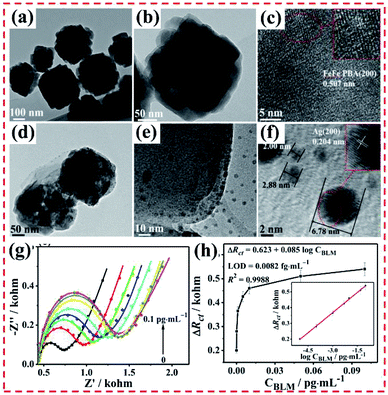 | ||
| Fig. 26 TEM and HR-TEM images of (a–c) CuFe@FeFe and (d–f) AgNCs/Apt@CuFe@FeFe PBAs. (g) EIS responses of the AgNCs/Apt@CuFe@FeFe/AE with different BLM concentrations. (h) Dependence of ΔRct on the concentration of BLM based on AgNCs/Apt@CuFe@FeFe/AE (inset: linear part of the calibration curve). Reproduced from ref. 192 with permission from the American Chemical Society, Copyright 2018. | ||
Significant work has been done on combining COFs and MOFs because MOF@COF hybrids possess the merits of each component. Our group developed a series of Ce-MOF and COF nanohybrids and exploited them as novel platforms for an oxytetracycline (OTC) aptasensor (Fig. 27a and b). Integrating the excellent sensing properties of Ce-MOF and good electrochemical activity of MCA, the Ce-MOF@MCA-based biosensor exhibited a very low LOD for detecting OTC and other good sensing ability in aqueous solution (Fig. 27c–f).95 Recently, our group prepared a Co-MOF@TPN-COF nanoarchitecture and used it as s platform after immobilizing the AMP-targeted aptamer (AMP: ampicillin) (Fig. 27g–k). Given that a large number of aptamer molecules were anchored on the Co-MOF@TPN-COF nanosheets via complex interaction, the developed Co-MOF@TPN–COF–based biosensor showed a low LOD of 0.217 fg mL−1 (Fig. 27l and m).94 The Ce-MOF@MCA and Co-MOF@TPN-COF heterostructures exhibited common features, as follows: (i) abundant nitrogen-functional groups in the COF component, which can greatly facilitate the adsorption of the aptamer stands; (ii) the conjugation of the COF and the electrochemically active Ce-MOF or Co-MOF can outstandingly amplify the electrochemical signal; and (iii) the porous nanostructures and large cavities in the heterostructures can allow the aptamer to adsorb over the heterostructure and permeate its interior, thus boosting the sensing ability and enhancing the G-quadruplex stability. Although great efforts have been dedicated to exploring new porous MOF@COF hybrids and to developing their applications in diverse fields, these materials are still in the early stage of advancement in the biosensing field.
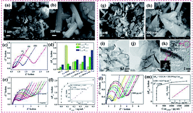 | ||
| Fig. 27 (a) and (b) SEM images of Ce-MOF@MCA500 nanohybrids. (c) EIS Nyquist plots of the OTC detection procedures using the electrochemical aptasensors based on Ce-MOF@MCA500 in 5 mM [Fe(CN)6]3−/4− containing 0.1 M KCl. (d) Corresponding variations in the Rct values of the five types of aptasensors for detecting OTC. (e) EIS Nyquist plots for the detection of different concentrations of OTC using the Ce-MOF@MCA500-based aptasensor. (f) Corresponding calibration curves between ΔRct and OTC concentrations (inset: the linear fit plot of ΔRct as a function of the logarithm of OTC concentration). Reproduced from ref. 95 with permission from Elsevier, Copyright 2019. (g) and (h) Low- and high-magnification FE-SEM images of Co-MOF@TPN-COF. (i, j, and k) TEM and HR-TEM images of Co-MOF@TPN-COF. (l) EIS responses of the Co-MOF@TPN–COF–based aptasensor with different AMP concentrations. (m) Dependence of ΔRct on the concentration of AMP. The linear parts of the calibration curves are shown in the inset of (l). Reproduced from ref. 94 with permission from Elsevier, Copyright 2019. | ||
In addition to their application as electrochemical biosensors, MOF-on-MOF and MOF@COF heterostructures have been used as fluorescence biosensors because of their remarkable fluorescence performances. Wang et al. proposed an MOF@COF to remove aggregation-caused quenching and to enhance the emission intensity of COFs (Fig. 28a and b). The abundant Zr4+ ions present in UiO-66 led to high binding affinity with the phosphate group to enhance the sensing selectivity, while the organic linker, BDC-NH2, which made the UiO-66 surface rich in amino groups, bound with the COF shell by covalent bonds. The multi-emission of the UiO@COF hybrids exhibited remarkable ratiometric sensing abilities toward PO43− and ATP, showing an LOD of 0.067 μM for PO43− and 0.038 μM for ATP, much lower than that of other types of sensors (Fig. 28c–f).80 According to the above discussion, the development of biosensors based on MOF-on-MOF and MOF@COF heterostructures is still in its early phase. The fabrication of sensitive, feasible, and wearable electrochemical biosensors using these porous organic frameworks as electrode materials remains undeveloped, and therefore needs further investigation in the biosensing field.
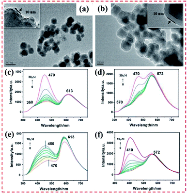 | ||
| Fig. 28 TEM images of (a) UiO@COF1 and (b) UiO@COF2. Fluorescence spectra (λex = 270 nm) of 0.1 mg mL−1 (c) UiO@COF1 and (d) UiO@COF2 upon the addition of PO43− in the concentration range of 0–30 μM. Fluorescence spectra (λex = 270 nm) of 0.1 mg mL−1 (e) UiO@COF-1 and (f) UiO@COF-2 upon the addition of ATP in the concentration range of 0–10 μM. Reproduced from ref. 80 with permission from the American Chemical Society, Copyright 2020. | ||
| Materials | Targeted sites | Application | Ref. |
|---|---|---|---|
| PB@ZIF-8 | HeLa tumor | Dual-mode MRI, fluorescence imaging, photothermal therapy | 62 |
| CS-MOFs@AS | HeLa tumor | pH-responsive chemotherapy, multimodality imaging | 227 |
| H2P-MOF@UiO-AM | HeLa cells | Photodynamic therapy | 77 |
| Hf-UiO-AM@HUC-PEG | HeLa tumor | Photodynamic and photothermal therapy, computed tomography/photothermal imaging | 82 |
| MIL-88B-on-UIO-66 | MCF-7 cells | Drug delivery | 52 |
| NMCTP-TTA | Infected wound | Catalytic microbicidal efficacy and wound healing | 91 |
ZIF-8 is often used as a promising drug carrier owing to its nontoxicity and remarkable biocompatibility.226 This MOF displays high pH-responsiveness as a drug-loading carrier in the acidic tumor microenvironment (pH 5.7–7.8) and high stability under normal physiological conditions. Therefore, combining PB and ZIF-8 can form a core–shell dual MOF with potential application as a drug delivery system with dual-mode-responsive abilities. Wang et al. reported a PB/ZIF-8 hybrid using PB as the core (Fig. 29a–c), which showed excellent chemo-PTT cancer therapy performances under NIR light. The ZIF-8 shell was then degraded and removed from the PB core. The inner PB particles were then irradiated by NIR light, generating heat to kill cancer cells. The results revealed its higher efficacy toward HeLa cancer cell lines than that of the single therapy mode (Fig. 29d). Thus, the obtained PB/ZIF-8 hybrid therapy system attained synergistic chemo-PTT therapy efficacy (Fig. 29e and f). The anti-tumor efficiency of CSD-MOFs@DOX + NIR was much higher than that of single mode therapy.62 The core–shell Mn3[Co(CN)6]2@MIL-100(Fe) (CS-MOFs) hybrid was prepared and utilized for the synchronous co-delivery of artesunate (AS) and ferric ions for cancer therapy. Owing to the fact that the Mn3[Co(CN)6]2@MIL-100(Fe) hybrid had a mesoporous nanostructure and high binding interaction with organic linkers, it exhibited a high loading capacity toward artesunate (AS) of 531 mg g−1. AS molecules were released from CS-MOFs at pH 5.0–6.5, but not released under physiological environment (pH ∼ 7.4). The efficient release of AS was observed due to the decomposition of the outer MIL-100(Fe) shell, leading to the on-demand release of Fe(III) ions and AS in the tumor tissue (Fig. 29j–l). The intracellular Fe(III) ions were transferred to Fe(II), resulting in the catalysis of AS to produce carbon free radicals and ROS. In comparison with free AS alone, the CS-MOFs@AS system demonstrated remarkably improved tumor delivery specificity, which was 5.79-times higher than that of free AS (Fig. 29m).227
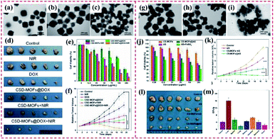 | ||
| Fig. 29 (a–c) TEM images of DOX@CSD-MOFs after drug release at pH = 7.4, 6.2 and 5.0, respectively. Error bars are based on triplicate measurements. (d) Photographs of tumors harvested from mice receiving different therapeutic treatments. (e) Relative viability of HeLa cells incubated with free DOX, CSD-MOFs@DOX, CSD-MOFs and CSD-MOFs@DOX with or without laser irradiation (1.6 W cm−2, 5 min). (f) Tumor growth curves of the corresponding group. Reproduced from ref. 62 with permission from Ivyspring International Publisher, Copyright 2017. (g–i) Corresponding TEM images of CSMOFs nanocubes in PBS solution with different pH values (pH 7.4 (panel (g))), pH 6.5 (panel (h)), and pH 5.0 (panel (i)) after the Fe(III) release process. (j) In vitro therapeutic efficacy. (k) Tumor growth curves of different groups of tumor-bearing mice after various treatments indicated every 2 days for 17 days. (l) Photographs of the tumors from different mice groups at day 17 after treatment and (m) biodistribution of CS-MOFs in HeLa-tumor-bearing mice at 24 h after IV injection. Reproduced from ref. 227 with permission from the American Chemical Society, Copyright 2017. | ||
As discussed above, the surface morphologies and sizes of MOF/COF hybrids can be modulated using the template strategy and surfactant-assisted emulsion approach.228 Zheng et al. reported a novel H2P-MOF@UiO-AM hybrid, where the photoactive porphyrin-MOF (H2P-MOF) was in situ grown on the outer UiO-AM–NH2 surface. The formed hybrid had a nanosize, which was smaller than 200 nm, showing the ability to be internalized by cancer cells (Fig. 30a and b). 1O2 species were generated by irradiating the H2P-MOF@UiO-AM hybrid, thus showing potential application in PDT (Fig. 30c–f).77 Zheng et al. obtained the Hf-UiO-AM@HUC-PEG hybrid (Fig. 30g and h), where its small particle size afforded improved uptake ability toward cancer cells. After endocytosis, the Hf-UiO-AM@HUC-PEG hybrid also produced cytotoxic 1O2 for PDT in vitro. Nevertheless, the porphyrin displayed a short excitation wavelength and low molar extinction coefficient, remarkably inhibiting the in vivo application of this hybrid. Tetratopic chlorin-doped Hf-UiO-66 showed spatial arrangement-dependent photochemical behavior, and thus potential application in PDT and PTT (Fig. 30i and j). Owing to the features of the Hf element, the proposed Hf-UiO-AM@HUC-PEG hybrid demonstrated computed tomography/photothermal imaging functions (Fig. 30k and l).82 In 2020, Zhang and co-workers proposed a novel MIL-88B-on-UiO-66 hybrid as a bifunctional drug delivery nanosystem. The in vitro anticancer effect of the prepared MIL-88B-on-UiO-66 was probed against MCF-7 breast cancer cells, and the results revealed its synergistic effect for 5-fluoracil (5-Fu) and alendronate (AL). This successful controlled drug release can provide a novel drug delivery nanosystem for combined cancer therapy.52
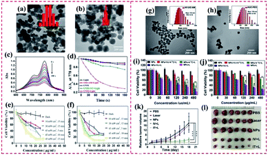 | ||
| Fig. 30 TEM images and hydrodynamic size distribution (inset) of (a) UiO-AM and (b) UNM. (c) Time-dependent UV absorption spectra of ICG at 778 nm with UNM in PBS after irradiation with a 450 nm lamp from 0 to 180 s. (d) Comparison of the decay rate of ICG alone (black), UiO-AM (red), UNM in the dark (blue), and UNM upon irradiation with (green) or without (pink) the vitamin C scavenger, respectively. In vitro photocytotoxicity of MOF@COF nanocomposites at different laser intensities, irradiation times, and PS concentrations against (e) HepG2 cells and (f) HeLa cells. Reproduced from ref. 77 with permission from the American Chemical Society, Copyright 2017. TEM images and corresponding DLS profiles of (g) Hf-UiO-AM and (h) HUC-PEG. Cell viability of (i) HeLa cells and (j) HepG2 cells after incubation with HUC-PEG with or without 671 nm light illumination. (k) Relative tumor volume changes of mice treated with PBS, PBS + laser, only HUC-PEG, and HUC-PEG by intravenous and intratumoral injection + laser. (l) Representative tumor photographs. Reproduced from ref. 82 with permission from Elsevier, Copyright 2020. | ||
Owing to the fact that some MOFs with peroxidase features can generate ROS, which play an important role in the eradication of bacteria by catalyzing the conversion of H2O2 into the highly toxic hydroxyl radical (˙OH), they show great potential as antibacterial agents. Qu’ group reported a novel MOF@COF nanozyme as a high-efficiency peroxidase mimic, which exhibited enhanced bacterial inhibition.91 For the synthesis of this MOF@COF nanozyme, the superficial COFTP-TTA was prepared on the surface of NH2–MIL-88B(Fe) using weak acidic (phenol) and basic functional (triazine) groups as building blocks. Due to its hierarchical nanocavities with tailored surface functional groups, COFTP-TTA served as enzyme binding pockets for the formation of a specific pore microenvironment around the active sites. The TEM image showed that a sparse and dendritic COFTP-TTA skin grew on the surface of NH2–MIL-88B(Fe)–CHO. The NH2–MIL-88B(Fe)@COFTP-TTA (denoted as NMCTP-TTA) nanozyme efficiently captured bacteria tightly via multivalent topological interactions, eventually leading to the death of the bacteria by the generated ROS. Both the in vitro and in vivo studies revealed its satisfactory catalytic microbicidal efficacy, which enabled a wound to become red quickly, displaying a nature-inspired strategy that can remarkably facilitate the design and construction of versatile enzyme mimics. To date, only five samples of MOF-on-MOF and MOF@COF hybrids have been applied as delivery systems of anticancer drugs and photosensitizers for cancer therapy. Although rapid progress has been achieved in the application of MOFs/COFs in cancer therapy, the use of MOF-on-MOF and MOF@COF conjugations as nanocatalytic medicine is still in the early stage. Most studies have concentrated on the preparation approaches of nano-scale MOF-on-MOF for different therapeutic fields, and the degradation behavior and in vivo chronic toxicity of these MOF-based conjugations have been rarely reported.
5. Conclusions and future outlook
Great efforts have been devoted to exploring the types, formation mechanism of heterostructures, and basic characteristics of new MOFs and COFs and their applications. Synthesizing diverse MOF/COF-based heterostructures with specific morphologies and shapes, new features, and synergistic effects is essential for the further development of advanced materials. To ameliorate the inferior electrochemical activities of most MOFs and COFs, their lack of multi-functional performances, and unsatisfactory stability in various environments, such as acidic and alkaline media or the physiological environment, hybrids or composites have been developed using various techniques to improve their potential applications. The integration of MOFs or MOFs and COFs, such as MOF-on-MOF, MOF@COF, and COF-to-COF hybrids, has been achieved by synthesizing guest MOFs or COFs on preformed host MOFs or COFs to overcome the above-mentioned disadvantages. These strategies provide much more possibilities for the development of novel MOF hybrids or MOF/COF heterostructures with new structural diversities and enhanced properties. Compared with the individual MOFs or COFs, the MOF/COF heterostructures normally exhibit the following fantastic properties due to their synergistic effects.(i) MOF/COF-based hybrid nanomaterials possess increased specific surface areas, large pores, and smaller band gaps. The properties of increased specific surface area and large pores favor the absorption of different types of pollutants, biomolecules (i.e., aptamer and antibody), anticancer drugs, and gas molecules. Besides, the smaller band bap increases the absorption of visible light, while the interface of the heterostructure enhances the transportation and separation of photogenerated charge and holes. Therefore, MOF/COF-based hybrid nanomaterials present intensive applications in photocatalysis, sorption or separation, molecular recognition, and drug delivery.
(ii) The integration of MOF and COF components can complement each other. For example, MOFs usually demonstrate poor stability due to their reversible coordination bond in water and other physiological environments, while COFs are more stable because of their strong covalent bond. Therefore, the hybridization of MOFs and COFs results in increased stability in water and other physiological environments. Also, by combining with conductive COFs, the electrochemical properties of MOF/COF-based hybrids such as electrochemical catalytic ability and electrochemical sensing ability can be improved.
(iii) Excellent synergistic properties are introduced, such as irregular morphologies, micro-and mesopores at the MOF/COF interface, and strong multi-emission property. The synergism of different components in MOF/COF-based composites is of great significance for the improvement of their application-related performances, such as irregular morphology for catalytic selectivity, gas sieving, ratiometric sensing, and enhanced drug delivery and cancer synergistic therapy.
Most pristine MOF/COF-based heterostructures exhibit potential applications in gas separation/adsorption, biosensing and biomedical fields, photocatalysis, and molecular catalysis. However, research on these materials is still in its infancy and needs to be expanded and improved.
(i) Together with the development of the state-of-art of hybrid materials, fabricating ternary or even multicomponent MOF/COF-based heterostructures is urgent for their diverse applications in the near future. Therefore, to overcome the inherent restrictions of structures, new construction approaches and formation mechanisms should be proposed.
(ii) It is a great challenge to explain the functions of each component since the structure–function relationship of hybrids become more sophisticated. Complicated experiments are usually required; thus, computational simulation can give scope to reduce the amount of work and help explain the specific mechanism in complicated applications.
(iii) Although the performances of MOF/COF hybrids are enhanced, their applications in diverse scopes such as catalysis, energy storage, and cancer diagnosis and therapy are greatly restricted due to their low content of catalytic sites, absence of excellent electrochemical activity, and complicated preparation procedures. Thus, it is still urgent to explore new types of MOF-on-MOF, MOF@COF, and COF-to-COF heterostructures with remarkable electroconductivity and superior catalytic activity. The combination of MOF/COF hybrids with the currently active frontier of single-atom catalysts (SACs) is a promising field.
Together with the development of synthetic chemistry, MOFs or COFs with diverse structures and functionality will be proliferated, leading to the booming development of MOF/COF-based heterostructures. The fast-emerging synthetic strategies also pave the way for the rational design and synthesis of novel MOF/COF-based heterostructures, showing great potential for expanding the practical application of MOF materials.
Conflicts of interest
There are no conflicts to declare.Acknowledgements
We are grateful to Henan Distinguished Youth Science Fund Project (202300410492), the National Natural Science Foundation of China (21571158) and the Key Research Project of University of Henan Province (19zx004) for financial support.Notes and references
- X. Zhang, Z. Chen, X. Liu, S. L. Hanna, X. Wang, R. Taheri-Ledari, A. Maleki, P. Li and O. K. Farha, Chem. Soc. Rev., 2020, 49, 7406–7427 RSC.
- X. Kang, X. Han, C. Yuan, C. Cheng, Y. Liu and Y. Cui, J. Am. Chem. Soc., 2020, 142, 16346–16356 CrossRef CAS PubMed.
- P. M. Bhatt, V. Guillerm, S. J. Datta, A. Shkurenko and M. Eddaoudi, Chem, 2020, 6, 1613–1633 CAS.
- S. Wang, C. M. McGuirk, A. D'Aquino, J. A. Mason and C. A. Mirkin, Adv. Mater., 2018, 30, 1800202 CrossRef PubMed.
- Y. Xue, S. Zheng, H. Xue and H. Pang, J. Mater. Chem. A, 2019, 7, 7301–7327 RSC.
- Y. Zheng, S. Zheng, H. Xue and H. Pang, J. Mater. Chem. A, 2019, 7, 3469–3491 RSC.
- S. Kuyuldar, D. T. Genna and C. Burda, J. Mater. Chem. A, 2019, 7, 21545–21576 RSC.
- S. Zhang, F. Rong, C. Guo, F. Duan, L. He, M. Wang, Z. Zhang, M. Kang and M. Du, Coord. Chem. Rev., 2021, 439, 213948 CrossRef CAS.
- U. Ryu, S. Jee, P. C. Rao, J. Shin, C. Ko, M. Yoon, K. S. Park and K. M. Choi, Coord. Chem. Rev., 2021, 426, 213544 CrossRef CAS PubMed.
- Q. Yang, M. Luo, K. Liu, H. Cao and H. Yan, Appl. Catal., B, 2020, 276, 119174 CrossRef CAS.
- T. Sick, J. M. Rotter, S. Reuter, S. Kandambeth, N. N. Bach, M. Döblinger, J. Merz, T. Clark, T. B. Marder, T. Bein and D. D. Medina, J. Am. Chem. Soc., 2019, 141, 12570–12581 CrossRef CAS.
- H. Ma, J. Zou, X. Li, G. Chen and Y. Dong, Chem.–Eur. J., 2020, 26, 13754–13770 CrossRef CAS PubMed.
- L. Feng, C. Qian and Y. Zhao, ACS Mater. Lett., 2020, 2, 1074–1092 CrossRef CAS.
- J. Li, X. Jing, Q. Li, S. Li, X. Gao, X. Feng and B. Wang, Chem. Soc. Rev., 2020, 49, 3565–3604 RSC.
- X. Cui, S. Lei, A. C. Wang, L. Gao, Q. Zhang, Y. Yang and Z. Lin, Nano Energy, 2020, 70, 104525 CrossRef CAS.
- Z. Chen, X. Li, C. Yang, K. Cheng, T. Tan, Y. Lv and Y. Liu, Adv. Sci., 2021, 8, 2101883 CrossRef PubMed.
- L. Garzón Tovar, J. Pérez Carvajal, A. Yazdi, J. Hernández Muñoz, P. Tarazona, I. Imaz, F. Zamora and D. Maspoch, Angew. Chem. Int. Ed., 2019, 58, 9512–9516 CrossRef PubMed.
- J. Ren, N. M. Musyoka, H. W. Langmi, B. C. North, M. Mathe and X. Kang, Int. J. Hydrogen Energy, 2014, 39, 14912–14917 CrossRef CAS.
- M. Du, Q. Li, Y. Zhao, C. Liu and H. Pang, Coord. Chem. Rev., 2020, 416, 213341 CrossRef CAS.
- L. Chen, X. Zhang, X. Cheng, Z. Xie, Q. Kuang and L. Zheng, Nanoscale Adv., 2020, 2, 2628–2647 RSC.
- J. W. M. Osterrieth and D. Fairen-Jimenez, Biotechnol. J., 2020, 16, 2000005 CrossRef PubMed.
- J. Xin, X. Wang, N. Li, L. Liu, Y. Lian, M. Wang and R. Zhao, Food Chem., 2020, 330, 127255 CrossRef CAS PubMed.
- D. Rodríguez-San-Miguel and F. Zamora, Chem. Soc. Rev., 2019, 48, 4375–4386 RSC.
- R. Haldar and C. Wöll, Nano Res., 2020, 14, 355–368 CrossRef.
- M. Wu, Y. Wang, G. Zhou and X. Liu, Coord. Chem. Rev., 2021, 430, 213735 CrossRef CAS.
- H. Zhang, C. Gu, M. Yao and S. Kitagawa, Adv. Energy Mater., 2021, 2100321 CrossRef.
- S. Subudhi, S. P. Tripathy and K. Parida, Inorg. Chem. Front., 2021, 8, 1619–1636 RSC.
- X. Liao, H. Fu, T. Yan and J. Lei, Biosens. Bioelectron., 2019, 146, 111743 CrossRef CAS.
- X. Kong, H. Deng, F. Yan, J. Kim, J. A. Swisher, B. Smit, O. M. Yaghi and J. A. Reimer, Science, 2013, 341, 882 CrossRef CAS PubMed.
- X. Yang, S. Yuan, L. Zou, H. Drake, Y. Zhang, J. Qin, A. Alsalme and H. Zhou, Angew. Chem. Int. Ed., 2018, 57, 3927–3932 CrossRef CAS PubMed.
- S. Furukawa, K. Hirai, K. Nakagawa, Y. Takashima, R. Matsuda, T. Tsuruoka, M. Kondo, R. Haruki, D. Tanaka, H. Sakamoto, S. Shimomura, O. Sakata and S. Kitagawa, Angew. Chem. Int. Ed., 2009, 48, 1766–1770 CrossRef CAS PubMed.
- G. Zhao, X. Xu, G. Zhu, J. Shi, Y. Li, S. Zhang, M. S. A. Hossain, K. C. W. Wu, J. Tang and Y. Yamauchi, Microporous Mesoporous Mater., 2020, 303, 110257 CrossRef CAS.
- H. Xu, L. Zhao, X. Liu, Q. Huang, Y. Wang, C. Hou, Y. Hou, J. Wang, F. Dang and J. Zhang, Adv. Funct. Mater., 2020, 30, 2006188 CrossRef CAS.
- Y. Pan, K. Sun, S. Liu, X. Cao, K. Wu, W. Cheong, Z. Chen, Y. Wang, Y. Li, Y. Liu, D. Wang, Q. Peng, C. Chen and Y. Li, J. Am. Chem. Soc., 2018, 140, 2610–2618 CrossRef CAS PubMed.
- O. Kwon, J. Y. Kim, S. Park, J. H. Lee, J. Ha, H. Park, H. R. Moon and J. Kim, Nat. Commun., 2019, 10, 3620 CrossRef PubMed.
- M. Zhang, K. Yang, J. Cui, H. Yu, Y. Wang, W. Shan, Z. Lou and Y. Xiong, Chem. Eng. J., 2020, 386, 124023 CrossRef CAS.
- K. Koh, A. G. Wong-Foy and A. J. Matzger, Chem. Commun., 2009, 6162–6164 RSC.
- M. Wu, Y. Wang, G. Zhou and X. Liu, ACS Appl. Mater. Interfaces, 2020, 12, 54285–54305 CrossRef CAS.
- V. Chernikova, O. Shekhah, I. Spanopoulos, P. N. Trikalitis and M. Eddaoudi, Chem. Commun., 2017, 53, 6191–6194 RSC.
- K. Ikigaki, K. Okada, Y. Tokudome, T. Toyao, P. Falcaro, C. J. Doonan and M. Takahashi, Angew. Chem. Int. Ed., 2019, 58, 6886–6890 CrossRef CAS PubMed.
- M. Yao, J. Xiu, Q. Huang, W. Li, W. Wu, A. Wu, L. Cao, W. Deng, G. Wang and G. Xu, Angew. Chem. Int. Ed., 2019, 58, 14915–14919 CrossRef CAS PubMed.
- S. Choi, T. Kim, H. Ji, H. J. Lee and M. Oh, J. Am. Chem. Soc., 2016, 138, 14434–14440 CrossRef CAS PubMed.
- C. Wu, K. Zhang, H. Wang, Y. Fan, S. Zhang, S. He, F. Wang, Y. Tao, X. Zhao, Y. Zhang, Y. Ma, Y. Lee and T. Li, J. Am. Chem. Soc., 2020, 142, 18503–18512 CrossRef CAS PubMed.
- J. Zhuang, L. Chou, B. T. Sneed, Y. Cao, P. Hu, L. Feng and C. Tsung, Small, 2015, 11, 5551–5555 CrossRef CAS PubMed.
- N. Zhou, F. Su, C. Guo, L. He, Z. Jia, M. Wang, Q. Jia, Z. Zhang and S. Lu, Biosens. Bioelectron., 2019, 123, 51–58 CrossRef CAS PubMed.
- M. Wang, M. Hu, Z. Li, L. He, Y. Song, Q. Jia, Z. Zhang and M. Du, Biosens. Bioelectron., 2019, 142, 111536 CrossRef PubMed.
- H. J. Lee, Y. J. Cho, W. Cho and M. Oh, ACS Nano, 2013, 7, 491–499 CrossRef PubMed.
- H. Ji, S. Lee, J. Park, T. Kim, S. Choi and M. Oh, Inorg. Chem., 2018, 57, 9048–9054 CrossRef CAS PubMed.
- D. Kim, G. Lee, S. Oh and M. Oh, Chem. Commun., 2019, 55, 43–46 RSC.
- G. Lee, S. Lee, S. Oh, D. Kim and M. Oh, J. Am. Chem. Soc., 2020, 142, 3042–3049 CrossRef CAS PubMed.
- S. Lee, S. Oh and M. Oh, Angew. Chem. Int. Ed., 2020, 59, 1327–1333 CrossRef CAS.
- X. Wang, L. Xu, M. Li and X. Zhang, Angew. Chem. Int. Ed., 2020, 59, 18078–18086 CrossRef CAS.
- W. Lee, H. Chien, Y. Lo, H. Chiu, T. Wang and D. Kang, ACS Appl. Mater. Interfaces, 2015, 7, 18353–18361 CrossRef CAS PubMed.
- J. Zhang, T. Zhang, K. Xiao, S. Cheng, G. Qian, Y. Wang and Y. Feng, Cryst. Growth Des., 2016, 16, 6494–6498 CrossRef CAS.
- W. Guo, W. Xia, K. Cai, Y. Wu, B. Qiu, Z. Liang, C. Qu and R. Zou, Small, 2017, 13, 1702049 CrossRef PubMed.
- S. H. Yuan, A. P. Isfahani, T. Yamamoto, A. Muchtar, C. Y. Wu, G. Huang, Y. C. You, E. Sivaniah, B. K. Chang and B. Ghalei, Small Methods, 2020, 4, 2000021 CrossRef CAS.
- K. C. Jayachandrababu, D. S. Sholl and S. Nair, J. Am. Chem. Soc., 2017, 139, 5906–5915 CrossRef CAS.
- Z. Song, F. Qiu, E. W. Zaia, Z. Wang, M. Kunz, J. Guo, M. Brady, B. Mi and J. J. Urban, Nano Lett., 2017, 17, 6752–6758 CrossRef CAS PubMed.
- L. Zhang, J. Wang, X. Ren, W. Zhang, T. Zhang, X. Liu, T. Du, T. Li and J. Wang, J. Mater. Chem. A, 2018, 6, 21029–21038 RSC.
- Y. Li, Y. Zhao, R. Zhang and G. Lu, Inorg. Chem. Commun., 2017, 82, 68–71 CrossRef CAS.
- H. Yi, R. Qin, S. Ding, Y. Wang, S. Li, Q. Zhao and F. Pan, Adv. Funct. Mater., 2020, 31, 2006970 CrossRef.
- D. Wang, J. Zhou, R. Shi, H. Wu, R. Chen, B. Duan, G. Xia, P. Xu, H. Wang, S. Zhou, C. Wang, H. Wang, Z. Guo and Q. Chen, Theranostics, 2017, 7, 4605–4617 CrossRef CAS PubMed.
- S. Wu, G. Zhuang, J. Wei, Z. Zhuang and Y. Yu, J. Mater. Chem. A, 2018, 6, 18234–18241 RSC.
- Y. Luo, J. Li, X. Liu, L. Tan, Z. Cui, X. Feng, X. Yang, Y. Liang, Z. Li, S. Zhu, Y. Zheng, K. W. K. Yeung, C. Yang, X. Wang and S. Wu, ACS Cent. Sci., 2019, 5, 1591–1601 CrossRef CAS PubMed.
- C. Li, X. Zhang, S. Wen, R. Xiang, Y. Han, W. Tang, T. Yue and Z. Li, J. Hazard. Mater., 2020, 395, 122615 CrossRef CAS.
- K. M. Choi, J. H. Park and J. K. Kang, Chem. Mater., 2015, 27, 5088–5093 CrossRef CAS.
- Y. Gong, Y. Yuan, C. Chen, P. Zhang, J. Wang, A. Khan, S. Zhuiykov, S. Chaemchuen and F. Verpoort, J. Catal., 2019, 375, 371–379 CrossRef CAS.
- M. Zhao, J. Chen, B. Chen, X. Zhang, Z. Shi, Z. Liu, Q. Ma, Y. Peng, C. Tan, X. Wu and H. Zhang, J. Am. Chem. Soc., 2020, 142, 8953–8961 CrossRef CAS PubMed.
- C. Liu, L. Lin, Q. Sun, J. Wang, R. Huang, W. Chen, S. Li, J. Wan, J. Zou and C. Yu, Chem. Sci., 2020, 11, 3680–3686 RSC.
- Y. Gu, Y. Wu, L. Li, W. Chen, F. Li and S. Kitagawa, Angew. Chem. Int. Ed., 2017, 56, 15658–15662 CrossRef CAS PubMed.
- M. Gao, M. Qi, L. Liu and Z. Han, Chem. Commun., 2019, 55, 6377–6380 RSC.
- H. Peng, J. Raya, F. Richard, W. Baaziz, O. Ersen, A. Ciesielski and P. Samorì, Angew. Chem. Int. Ed., 2020, 59, 19602–19609 CrossRef CAS PubMed.
- F. Li, D. Wang, Q. Xing, G. Zhou, S. Liu, Y. Li, L. Zheng, P. Ye and J. Zou, Appl. Catal., B, 2019, 243, 621–628 CrossRef CAS.
- Y. Peng, M. Zhao, B. Chen, Z. Zhang, Y. Huang, F. Dai, Z. Lai, X. Cui, C. Tan and H. Zhang, Adv. Mater., 2018, 30, 1705454 CrossRef PubMed.
- J. Winarta, B. Shan, S. M. Mcintyre, L. Ye, C. Wang, J. Liu and B. Mu, Cryst. Growth Des., 2020, 20, 1347–1362 CrossRef CAS.
- H. Tang, X. Sun and F. Zhang, Dalton Trans., 2020, 49, 12136–12144 RSC.
- X. Zheng, L. Wang, Q. Pei, S. He, S. Liu and Z. Xie, Chem. Mater., 2017, 29, 2374–2381 CrossRef CAS.
- Y. Cheng, Y. Ying, L. Zhai, G. Liu, J. Dong, Y. Wang, M. P. Christopher, S. Long, Y. Wang and D. Zhao, J. Membr. Sci., 2019, 573, 97–106 CrossRef CAS.
- M. Qi, M. Gao, L. Liu and Z. Han, Inorg. Chem., 2018, 57, 14467–14470 CrossRef CAS PubMed.
- X. Wang, H. Yin and X. Yin, ACS Appl. Mater. Interfaces, 2020, 12, 20973–20981 CrossRef CAS PubMed.
- Y. Chen, D. Yang, B. Shi, W. Dai, H. Ren, K. An, Z. Zhou, Z. Zhao, W. Wang and Z. Jiang, J. Mater. Chem. A, 2020, 8, 7724–7732 RSC.
- X. Zheng, L. Wang, Y. Guan, Q. Pei, J. Jiang and Z. Xie, Biomaterials, 2020, 235, 119792 CrossRef CAS PubMed.
- J. L. Segura, S. Royuela and M. Mar Ramos, Chem. Soc. Rev., 2019, 48, 3903–3945 RSC.
- Y. Zhu, W. D. Wang, X. Sun, M. Fan, X. Hu and Z. Dong, ACS Appl. Mater. Interfaces, 2020, 12, 7285–7294 CrossRef CAS PubMed.
- D. Sun and D. Kim, ACS Appl. Mater. Interfaces, 2020, 12, 20589–20595 CrossRef CAS PubMed.
- J. Zhu, P. Li, W. Guo, Y. Zhao and R. Zou, Coord. Chem. Rev., 2018, 359, 80–101 CrossRef CAS.
- Y. Yan, C. Li, Y. Wu, J. Gao and Q. Zhang, J. Mater. Chem. A, 2020, 8, 15245–15270 RSC.
- D. Sun, S. Jang, S. Yim, L. Ye and D. Kim, Adv. Funct. Mater., 2018, 28, 1707110 CrossRef.
- S. He, Q. Rong, H. Niu and Y. Cai, Appl. Catal., B, 2019, 247, 49–56 CrossRef CAS.
- M. Cai, Y. Li, Q. Liu, Z. Xue, H. Wang, Y. Fan, K. Zhu, Z. Ke, C. Su and G. Li, Adv. Sci., 2019, 6, 1802365 CrossRef PubMed.
- L. Zhang, Z. Liu, Q. Deng, Y. Sang, K. Dong, J. Ren and X. Qu, Angew. Chem. Int. Ed., 2021, 60, 3469–3474 CrossRef CAS PubMed.
- S. Lv, J. Liu, F. Yang, C. Li and S. Wang, Chem. Eng. J., 2021, 409, 128269 CrossRef CAS.
- J. Fu, S. Das, G. Xing, T. Ben, V. Valtchev and S. Qiu, J. Am. Chem. Soc., 2016, 138, 7673–7680 CrossRef CAS PubMed.
- X. Liu, M. Hu, M. Wang, Y. Song, N. Zhou, L. He and Z. Zhang, Biosens. Bioelectron., 2019, 123, 59–68 CrossRef CAS PubMed.
- N. Zhou, Y. Ma, B. Hu, L. He, S. Wang, Z. Zhang and S. Lu, Biosens. Bioelectron., 2019, 127, 92–100 CrossRef CAS PubMed.
- H. Fan, A. Mundstock, A. Feldhoff, A. Knebel, J. Gu, H. Meng and J. Caro, J. Am. Chem. Soc., 2018, 140, 10094–10098 CrossRef CAS PubMed.
- Y. Ying, M. Tong, S. Ning, S. K. Ravi, S. B. Peh, S. C. Tan, S. J. Pennycook and D. Zhao, J. Am. Chem. Soc., 2020, 142, 4472–4480 CrossRef CAS PubMed.
- H. Xu, Y. Yang, X. Yang, J. Cao, W. Liu and Y. Tang, J. Mater. Chem. A, 2019, 7, 8284–8291 RSC.
- J. Ha and H. R. Moon, CrystEngComm, 2021, 23, 2337–2354 RSC.
- J. Tang, R. R. Salunkhe, J. Liu, N. L. Torad, M. Imura, S. Furukawa and Y. Yamauchi, J. Am. Chem. Soc., 2015, 137, 1572–1580 CrossRef CAS PubMed.
- Y. Pan, K. Sun, S. Liu, X. Cao, K. Wu, W. Cheong, Z. Chen, Y. Wang, Y. Li, Y. Liu, D. Wang, Q. Peng, C. Chen and Y. Li, J. Am. Chem. Soc., 2018, 140, 2610–2618 CrossRef CAS.
- Z. Hu, Z. Zhang, Z. Li, M. Dou and F. Wang, ACS Appl. Mater. Interfaces, 2017, 9, 16109–16116 CrossRef CAS PubMed.
- H. Park, S. Oh, S. Lee, S. Choi and M. Oh, Appl. Catal., B, 2019, 246, 322–329 CrossRef CAS.
- M. Huang, K. Mi, J. Zhang, H. Liu, T. Yu, A. Yuan, Q. Kong and S. Xiong, J. Mater. Chem. A, 2017, 5, 266–274 RSC.
- J. Yang, F. Zhang, H. Lu, X. Hong, H. Jiang, Y. Wu and Y. Li, Angew. Chem. Int. Ed., 2015, 54, 10889–10893 CrossRef CAS PubMed.
- Y. Huang, X. Sun, S. Huo, Y. Li and C. Zhong, Appl. Surf. Sci., 2019, 466, 637–646 CrossRef CAS.
- G. Zhan and H. C. Zeng, Nat. Commun., 2018, 9, 3778 CrossRef PubMed.
- M. Pan, Y. Zhu, K. Wu, L. Chen, Y. Hou, S. Yin, H. Wang, Y. Fan and C. Su, Angew. Chem. Int. Ed., 2017, 56, 14582–14586 CrossRef CAS PubMed.
- A. L. Medina-Castillo, J. F. Fernández-Sánchez and A. Fernández-Gutiérrez, Adv. Funct. Mater., 2011, 21, 3488–3495 CrossRef CAS.
- S. A. A. Razavi and A. Morsali, Chem.–Eur. J., 2019, 25, 10876–10885 CrossRef CAS PubMed.
- J. A. Boissonnault, A. G. Wong-Foy and A. J. Matzger, J. Am. Chem. Soc., 2017, 139, 14841–14844 CrossRef CAS PubMed.
- C. Guo, J. Guo, Y. Zhang, D. Wang, L. Zhang, Y. Guo, W. Ma and J. Wang, CrystEngComm, 2018, 20, 7659–7665 RSC.
- X. Song, T. K. Kim, H. Kim, D. Kim, S. Jeong, H. R. Moon and M. S. Lah, Chem. Mater., 2012, 24, 3065–3073 CrossRef CAS.
- R. Lin, B. Villacorta Hernandez, L. Ge and Z. Zhu, J. Mater. Chem. A, 2018, 6, 293–312 RSC.
- F. Zhang, J. Sheng, Z. Yang, X. Sun, H. Tang, M. Lu, H. Dong, F. Shen, J. Liu and Y. Lan, Angew. Chem. Int. Ed., 2018, 57, 12106–12110 CrossRef CAS PubMed.
- H. L. Nguyen, F. Gándara, H. Furukawa, T. L. H. Doan, K. E. Cordova and O. M. Yaghi, J. Am. Chem. Soc., 2016, 138, 4330–4333 CrossRef CAS PubMed.
- L. Feng, K. Wang, X. Lv, T. Yan, J. Li and H. Zhou, J. Am. Chem. Soc., 2020, 142, 3069–3076 CrossRef CAS PubMed.
- W. Sun, X. Tang, Q. Yang, Y. Xu, F. Wu, S. Guo, Y. Zhang, M. Wu and Y. Wang, Adv. Mater., 2019, 31, 1903176 CrossRef PubMed.
- F. Song, W. Li and Y. Sun, Inorganics, 2017, 5, 40 CrossRef.
- Y. Fu, G. Zeng, C. Lai, D. Huang, L. Qin, H. Yi, X. Liu, M. Zhang, B. Li, S. Liu, L. Li, M. Li, W. Wang, Y. Zhang and Z. Pi, Chem. Eng. J., 2020, 399, 125743 CrossRef CAS.
- Y. Li, M. Zhou, B. Cheng and Y. Shao, J. Mater. Sci. Technol., 2020, 56, 1–17 CrossRef.
- X. Liu, S. Gu, Y. Zhao, G. Zhou and W. Li, J. Mater. Sci. Technol., 2020, 56, 45–68 CrossRef.
- B. Gui, Y. Meng, Y. Xie, J. Tian, G. Yu, W. Zeng, G. Zhang, S. Gong, C. Yang, D. Zhang and C. Wang, Adv. Mater., 2018, 30, 1802329 CrossRef PubMed.
- X. Huang, T. Shen, T. Zhang, H. Qiu, X. Gu, Z. Ali and Y. Hou, Adv. Energy Mater., 2020, 10, 1900375 CrossRef CAS.
- C. Lin, D. Zhang, Z. Zhao and Z. Xia, Adv. Mater., 2018, 30, 1703646 CrossRef PubMed.
- X. Feng, X. Ding and D. Jiang, Chem. Soc. Rev., 2012, 41, 6010–6022 RSC.
- G. Lu, X. Huang, Y. Li, G. Zhao, G. Pang and G. Wang, J. Energy Chem., 2020, 43, 8–15 CrossRef.
- M. Fatima, R. Farooq, R. W. Lindström and M. Saeed, J. Mol. Liq., 2017, 246, 275–281 CrossRef CAS.
- V. Vaiano, O. Sacco, D. Sannino and P. Ciambelli, Chem. Eng. J., 2015, 261, 3–8 CrossRef CAS.
- Y. A. Attia, D. Buceta, C. Blanco-Varela, M. B. Mohamed, G. Barone and M. A. López-Quintela, J. Am. Chem. Soc., 2014, 136, 1182–1185 CrossRef CAS PubMed.
- D. Bahnemann, Sol. Energy, 2004, 77, 445–459 CrossRef CAS.
- X. Yang, Z. Chen, W. Zhao, C. Liu, X. Qian, M. Zhang, G. Wei, E. Khan, Y. Hau Ng and Y. Sik Ok, Chem. Eng. J., 2021, 405, 126806 CrossRef CAS PubMed.
- Z. He, J. Zhang, X. Li, S. Guan, M. Dai and S. Wang, Small, 2020, 16, 2005051 CrossRef CAS PubMed.
- Y. Liu, D. Huang, M. Cheng, Z. Liu, C. Lai, C. Zhang, C. Zhou, W. Xiong, L. Qin, B. Shao and Q. Liang, Coord. Chem. Rev., 2020, 409, 213220 CrossRef CAS.
- C. Wang, X. Wang and W. Liu, Chem. Eng. J., 2020, 391, 123601 CrossRef CAS.
- N. Askari, M. Beheshti, D. Mowla and M. Farhadian, Chemosphere, 2020, 251, 126453 CrossRef CAS.
- L. Zhang, L. Feng, P. Li, X. Chen, J. Jiang, S. Zhang, C. Zhang, A. Zhang, G. Chen and H. Wang, Chem. Eng. J., 2020, 395, 125072 CrossRef CAS.
- S. S. Chen, C. Hu, C. Liu, Y. Chen, T. Ahamad, S. M. Alshehri, P. Huang and K. C. W. Wu, J. Hazard. Mater., 2020, 397, 122431 CrossRef CAS PubMed.
- W. Li, J. Cao, W. Xiong, Z. Yang, S. Sun, M. Jia and Z. Xu, Chem. Eng. J., 2020, 392, 124844 CrossRef CAS.
- Q. Wu, H. Yang, L. Kang, Z. Gao and F. Ren, Appl. Catal., B, 2020, 263, 118282 CrossRef CAS.
- R. Yin, Y. Chen, S. He, W. Li, L. Zeng, W. Guo and M. Zhu, J. Hazard. Mater., 2020, 388, 121996 CrossRef CAS PubMed.
- X. Yang, C. Chen, Y. Zhang, L. Cai, B. Tan and J. Zhang, Dalton Trans., 2016, 45, 4522–4527 RSC.
- M. Jaishankar, T. Tseten, N. Anbalagan, B. B. Mathew and K. N. Beeregowda, Interdiscipl. Toxicol., 2014, 7, 60–72 CrossRef PubMed.
- J. Liu, F. Yang, Q. Zhang, W. Chen, Y. Gu and Q. Chen, Inorg. Chem., 2019, 58, 3564–3568 CrossRef CAS PubMed.
- M. Firoozi, Z. Rafiee and K. Dashtian, ACS Omega, 2020, 5, 9420–9428 CrossRef CAS PubMed.
- M. A. Islam, M. J. Angove and D. W. Morton, J. Environ. Nanotechnol., 2019, 12, 100267 Search PubMed.
- A. Tkaczyk, K. Mitrowska and A. Posyniak, Sci. Total Environ., 2020, 717, 137222 CrossRef CAS PubMed.
- A. Ahmad, S. H. Mohd-Setapar, C. S. Chuong, A. Khatoon, W. A. Wani, R. Kumar and M. Rafatullah, RSC Adv., 2015, 5, 30801–30818 RSC.
- Y. Tong, G. Xue, H. Wang, M. Liu, J. Wang, C. Hao, X. Zhang, D. Wang, X. Shi, W. Liu, G. Li and Z. Tang, Nanoscale, 2018, 10, 16425–16430 RSC.
- S. Cho, B. Ma, S. T. Nguyen, J. T. Hupp and T. E. Albrecht-Schmitt, Chem. Commun., 2006, 2563–2565 RSC.
- S. Huber, M. Cokoja and F. E. Kühn, J. Organomet. Chem., 2014, 751, 25–32 CrossRef CAS.
- M. P. van der Helm, B. Klemm and R. Eelkema, Nat. Rev. Chem., 2019, 3, 491–508 CrossRef CAS.
- Y. Zhong, Z. Pan, X. Wang, J. Yang, Y. Qiu, S. Xu, Y. Lu, Q. Huang and W. Li, Adv. Sci., 2019, 6, 1802243 CrossRef PubMed.
- D. Sun, L. Ye and Z. Li, Appl. Catal., B, 2015, 164, 428–432 CrossRef CAS.
- F. Dawood, M. Anda and G. M. Shafiullah, Int. J. Hydrogen Energy, 2020, 45, 3847–3869 CrossRef CAS.
- Y. Liu, D. Liu, Q. Yang, C. Zhong and J. Mi, Ind. Eng. Chem. Res., 2010, 49, 2902–2906 CrossRef CAS.
- P. Á. Szilágyi, M. Lutz, J. Gascon, J. Juan-Alcañiz, J. van Esch, F. Kapteijn, H. Geerlings, B. Dam and R. van de Krol, CrystEngComm, 2013, 15, 6003–6008 RSC.
- D. K. Panchariya, R. K. Rai, E. Anil Kumar and S. K. Singh, ACS Omega, 2018, 3, 167–175 CrossRef CAS PubMed.
- Y. Wang, X. Zhao, H. Yang, X. Bu, Y. Wang, X. Jia, J. Li and P. Feng, Angew. Chem. Int. Ed., 2019, 58, 6316–6320 CrossRef CAS PubMed.
- J. Park, N. F. Attia, M. Jung, M. E. Lee, K. Lee, J. Chung and H. Oh, Energy, 2018, 158, 9–16 CrossRef CAS.
- S. Yousef, J. Šereika, A. Tonkonogovas, T. Hashem and A. Mohamed, Environ. Technol. Innovation, 2021, 21, 101339 CrossRef CAS.
- Y. He, M. Sun, Q. Zhao, J. Shang, Y. Tian, P. Xiao, Q. Gu, L. Li and P. A. Webley, ACS Appl. Mater. Interfaces, 2019, 11, 30234–30239 CrossRef CAS PubMed.
- J. Gao, X. Qian, R. Lin, R. Krishna, H. Wu, W. Zhou and B. Chen, Angew. Chem. Int. Ed., 2020, 59, 4396–4400 CrossRef CAS PubMed.
- S. Dong, L. Peng, W. Wei and T. Huang, ACS Appl. Mater. Interfaces, 2018, 10, 14665–14672 CrossRef CAS PubMed.
- Q. Zhu, W. Zhang, H. Zhang, R. Yuan and H. He, J. Mater. Chem. C, 2020, 8, 16984–16991 RSC.
- J. Lei, R. Qian, P. Ling, L. Cui and H. Ju, TrAC, Trends Anal. Chem., 2014, 58, 71–78 CrossRef CAS.
- J. Zhou, Y. Li, W. Wang, X. Tan, Z. Lu and H. Han, Biosens. Bioelectron., 2020, 164, 112332 CrossRef CAS PubMed.
- H. Liang, M. Xu, Y. Zhu, L. Wang, Y. Xie, Y. Song and L. Wang, ACS Appl. Nano Mater., 2020, 3, 555–562 CrossRef CAS.
- M. Ko, L. Mendecki, A. M. Eagleton, C. G. Durbin, R. M. Stolz, Z. Meng and K. A. Mirica, J. Am. Chem. Soc., 2020, 142, 11717–11733 CrossRef CAS PubMed.
- S. Liu, J. Bai, Y. Huo, B. Ning, Y. Peng, S. Li, D. Han, W. Kang and Z. Gao, Biosens. Bioelectron., 2020, 149, 111801 CrossRef CAS PubMed.
- X. Qiao, B. Su, C. Liu, Q. Song, D. Luo, G. Mo and T. Wang, Adv. Mater., 2018, 30, 1702275 CrossRef PubMed.
- Y. Peng, H. Huang, Y. Zhang, C. Kang, S. Chen, L. Song, D. Liu and C. Zhong, Nat. Commun., 2018, 9, 187 CrossRef PubMed.
- S. Dong, D. Zhang, H. Cui and T. Huang, Sens. Actuators, B, 2019, 284, 354–361 CrossRef CAS.
- C. Gu, C. Guo, Z. Li, M. Wang, N. Zhou, L. He, Z. Zhang and M. Du, Biosens. Bioelectron., 2019, 134, 8–15 CrossRef CAS PubMed.
- L. Yao, F. Yang, G. Hu, Y. Yang, W. Huang, W. Liang, R. Yuan and D. Xiao, Biosens. Bioelectron., 2020, 155, 112099 CrossRef CAS PubMed.
- M. Wang, M. Hu, J. Liu, C. Guo, D. Peng, Q. Jia, L. He, Z. Zhang and M. Du, Biosens. Bioelectron., 2019, 132, 8–16 CrossRef CAS PubMed.
- A. Afzalinia and M. Mirzaee, ACS Appl. Mater. Interfaces, 2020, 12, 16076–16087 CrossRef CAS PubMed.
- H. Tan, X. Wu, Y. Weng, Y. Lu and Z. Huang, Anal. Chem., 2020, 92, 3447–3454 CrossRef CAS PubMed.
- L. He, F. Duan, Y. Song, C. Guo, H. Zhao, J. Tian, Z. Zhang, C. Liu, X. Zhang, P. Wang, M. Du and S. Fang, 2D Materials, 2017, 4, 25098 CrossRef.
- S. Khatua, S. Goswami, S. Biswas, K. Tomar, H. S. Jena and S. Konar, Chem. Mater., 2015, 27, 5349–5360 CrossRef CAS.
- Y. H. Cheng, D. Barpaga, J. A. Soltis, V. Shutthanandan, R. Kargupta, K. S. Han, B. P. McGrail, R. K. Motkuri, S. Basuray and S. Chatterjee, ACS Appl. Mater. Interfaces, 2020, 12, 10503–10514 CrossRef CAS PubMed.
- A. Yousefzadeh, J. Hassanzadeh, S. M. J. Mousavi and M. Yousefzadeh, Sens. Actuators, B, 2019, 286, 154–162 CrossRef CAS.
- X. Kuang, S. Ye, X. Li, Y. Ma, C. Zhang and B. Tang, Chem. Commun., 2016, 52, 5432–5435 RSC.
- Y. Wang, L. Wang, W. Huang, T. Zhang, X. Hu, J. A. Perman and S. Ma, J. Mater. Chem. A, 2017, 5, 8385–8393 RSC.
- X. Yang, Y. Yu, L. Peng, Y. Lei, Y. Chai, R. Yuan and Y. Zhuo, Anal. Chem., 2018, 90, 3995–4002 CrossRef CAS PubMed.
- F. Wang, X. Chen, L. Chen, J. Yang and Q. Wang, Mater. Sci. Eng. C, 2019, 96, 41–50 CrossRef CAS PubMed.
- D. Zou, L. Yu, Q. Sun, Y. Hui, Tengjisi, Y. Liu, G. Yang, D. Wibowo and C. Zhao, Colloids Surf., B, 2020, 193, 111108 CrossRef CAS PubMed.
- M. Ding, R. W. Flaig, H. Jiang and O. M. Yaghi, Chem. Soc. Rev., 2019, 48, 2783–2828 RSC.
- M. Lu, Y. Deng, Y. Li, T. Li, J. Xu, S. Chen and J. Wang, Anal. Chim. Acta, 2020, 1110, 35–43 CrossRef CAS PubMed.
- Z. Zhang, F. Duan, J. Tian, J. He, L. Yang, H. Zhao, S. Zhang, C. Liu, L. He, M. Chen, D. Chen and M. Du, ACS Sens., 2017, 2, 982–989 CrossRef CAS PubMed.
- Y. Seok Kim, N. H. Ahmad Raston and M. Bock Gu, Biosens. Bioelectron., 2016, 76, 2–19 CrossRef CAS PubMed.
- N. Zhou, L. Yang, B. Hu, Y. Song, L. He, W. Chen, Z. Zhang, Z. Liu and S. Lu, Anal. Chem., 2018, 90, 13624–13631 CrossRef CAS PubMed.
- F. Duan, M. Hu, C. Guo, Y. Song, M. Wang, L. He, Z. Zhang, R. Pettinari and L. Zhou, Chem. Eng. J., 2020, 398, 125452 CrossRef CAS.
- P. Sun, J. Hai, S. Sun, S. Lu, S. Liu, H. Liu, F. Chen and B. Wang, Nanoscale, 2020, 12, 825–831 RSC.
- P. Vineis and C. P. Wild, The Lancet, 2014, 383, 549–557 CrossRef.
- A. Pandey, N. Dhas, P. Deshmukh, C. Caro, P. Patil, M. Luisa García-Martín, B. Padya, A. Nikam, T. Mehta and S. Mutalik, Coord. Chem. Rev., 2020, 409, 213212 CrossRef CAS.
- J. Feng, W. Ren, F. Kong and Y. Dong, Inorg. Chem. Front., 2021, 8, 848–879 RSC.
- Y. Wang, X. Liu, W. Wu, D. Mao, B. Wang, G. Tang and B. Liu, Adv. Ther., 2020, 3, 2000011 CrossRef CAS.
- Y. Weng, S. Guan, L. Wang, H. Lu, X. Meng, G. I. N. Waterhouse and S. Zhou, Small, 2020, 16, 1905184 CrossRef CAS PubMed.
- B. Yang, L. Ding, H. Yao, Y. Chen and J. Shi, Adv. Mater., 2020, 32, 1907152 CrossRef CAS PubMed.
- W. Shang, L. Peng, P. Guo, H. Hui, X. Yang and J. Tian, ACS Biomater. Sci. Eng., 2020, 6, 1008–1016 CrossRef CAS PubMed.
- D. Zhang, Z. Ye, L. Wei, H. Luo and L. Xiao, ACS Appl. Mater. Interfaces, 2019, 11, 39594–39602 CrossRef CAS PubMed.
- J. Lu, L. Yang, W. Zhang, P. Li, X. Gao, W. Zhang, H. Wang and B. Tang, Chem. Commun., 2019, 55, 10792–10795 RSC.
- Y. Zhang, H. Fu, S. Chen, B. Liu, W. Sun and H. Gao, Chem. Commun., 2020, 56, 762–765 RSC.
- Z. Deng, C. Fang, X. Ma, X. Li, Y. Zeng and X. Peng, ACS Appl. Mater. Interfaces, 2020, 12, 20321–20330 CrossRef CAS PubMed.
- L. Zhang, Y. Gao, S. Sun, Z. Li, A. Wu and L. Zeng, J. Mater. Chem. B, 2020, 8, 1739–1747 RSC.
- L. He, Q. Ni, J. Mu, W. Fan, L. Liu, Z. Wang, L. Li, W. Tang, Y. Liu, Y. Cheng, L. Tang, Z. Yang, Y. Liu, J. Zou, W. Yang, O. Jacobson, F. Zhang, P. Huang and X. Chen, J. Am. Chem. Soc., 2020, 142, 6822–6832 CrossRef CAS PubMed.
- Y. Shao, B. Liu, Z. Di, G. Zhang, L. Sun, L. Li and C. Yan, J. Am. Chem. Soc., 2020, 142, 3939–3946 CrossRef CAS PubMed.
- L. Wang, X. Qu, Y. Zhao, Y. Weng, G. I. N. Waterhouse, H. Yan, S. Guan and S. Zhou, ACS Appl. Mater. Interfaces, 2019, 11, 35228–35237 CrossRef CAS PubMed.
- Z. Cai, F. Xin, Z. Wei, M. Wu, X. Lin, X. Du, G. Chen, D. Zhang, Z. Zhang, X. Liu and C. Yao, Adv. Healthcare Mater., 2020, 9, 1900996 CrossRef CAS PubMed.
- Q. Fang, J. Wang, S. Gu, R. B. Kaspar, Z. Zhuang, J. Zheng, H. Guo, S. Qiu and Y. Yan, J. Am. Chem. Soc., 2015, 137, 8352–8355 CrossRef CAS PubMed.
- K. Zhao, P. Gong, J. Huang, Y. Huang, D. Wang, J. Peng, D. Shen, X. Zheng, J. You and Z. Liu, Microporous Mesoporous Mater., 2021, 311, 110713 CrossRef CAS.
- L. Bai, S. Z. F. Phua, W. Q. Lim, A. Jana, Z. Luo, H. P. Tham, L. Zhao, Q. Gao and Y. Zhao, Chem. Commun., 2016, 52, 4128–4131 RSC.
- M. C. Scicluna and L. Vella-Zarb, ACS Appl. Nano Mater., 2020, 3, 3097–3115 CrossRef CAS.
- S. Liu, J. Yang, R. Guo, L. Deng, A. Dong and J. Zhang, Macromol. Rapid Commun., 2020, 41, 1900570 CrossRef CAS PubMed.
- S. Mitra, H. S. Sasmal, T. Kundu, S. Kandambeth, K. Illath, D. Díaz Díaz and R. Banerjee, J. Am. Chem. Soc., 2017, 139, 4513–4520 CrossRef CAS PubMed.
- G. Zhang, X. Li, Q. Liao, Y. Liu, K. Xi, W. Huang and X. Jia, Nat. Commun., 2018, 9, 2785 CrossRef PubMed.
- P. Bhanja, S. Mishra, K. Manna, A. Mallick, K. Das Saha and A. Bhaumik, ACS Appl. Mater. Interfaces, 2017, 9, 31411–31423 CrossRef CAS PubMed.
- H. Wang, W. Zhu, L. Feng, Q. Chen, Y. Chao, Z. Dong and Z. Liu, Nano Res., 2018, 11, 3244–3257 CrossRef CAS.
- Q. Guan, D. Fu, Y. Li, X. Kong, Z. Wei, W. Li, S. Zhang and Y. Dong, iScience, 2019, 14, 180–198 CrossRef CAS PubMed.
- D. Tao, L. Feng, Y. Chao, C. Liang, X. Song, H. Wang, K. Yang and Z. Liu, Adv. Funct. Mater., 2018, 28, 1804901 CrossRef.
- Q. Guan, L. Zhou, Y. Li, W. Li, S. Wang, C. Song and Y. Dong, ACS Nano, 2019, 13, 13304–13316 CrossRef CAS PubMed.
- K. Wang, Z. Zhang, L. Lin, K. Hao, J. Chen, H. Tian and X. Chen, ACS Appl. Mater. Interfaces, 2019, 11, 39503–39512 CrossRef CAS PubMed.
- Y. Shi, S. Liu, Y. Liu, C. Sun, M. Chang, X. Zhao, C. Hu and M. Pang, ACS Appl. Mater. Interfaces, 2019, 11, 12321–12326 CrossRef CAS PubMed.
- K. Wang, Z. Zhang, L. Lin, J. Chen, K. Hao, H. Tian and X. Chen, Chem. Mater., 2019, 31, 3313–3323 CrossRef CAS.
- Z. Qin, Y. Li and N. Gu, Adv. Healthcare Mater., 2018, 7, 1800347 CrossRef PubMed.
- D. Wang, J. Zhou, R. Chen, R. Shi, C. Wang, J. Lu, G. Zhao, G. Xia, S. Zhou, Z. Liu, H. Wang, Z. Guo and Q. Chen, Chem. Mater., 2017, 29, 3477–3489 CrossRef CAS.
- H. Guan, R. J. LeBlanc, S. Xie and Y. Yue, Coord. Chem. Rev., 2018, 369, 76–90 CrossRef CAS.
| This journal is © The Royal Society of Chemistry 2022 |

