 Open Access Article
Electrokinetic separation techniques for studying nano- and microplastics
Jonathan R.
Thompson
 and
Richard M.
Crooks
 *
*
Department of Chemistry and Texas Materials Institute, The University of Texas at Austin, 105 E. 24th St., Stop A5300, Austin, Texas 78712-1224, USA. E-mail: crooks@cm.utexas.edu; Tel: +1-512-475-8674
First published on 24th October 2022
Abstract
In recent years, microplastics have been found in seawater, soil, food, and even human blood and tissues. The ubiquity of microplastics is alarming, but the health and environmental impacts of microplastics are just beginning to be understood. Accordingly, sampling, separating, and quantifying exposure to microplastics to devise a total risk assessment is the focus of ongoing research. Unfortunately, traditional separation methods (i.e., size- and density-based methods) unintentionally exclude the smallest microplastics (<10 μm). Limited data about the smallest microplastics is problematic because they are likely the most pervasive and have distinct properties from their larger plastic counterparts. To that end, in this Perspective, we discuss using electrokinetic methods for separating the smallest microplastics. Specifically, we describe three methods for forming electric field gradients, discuss key results within the field for continuously separating microplastics, and lastly discuss research avenues which we deem critical for advancing electrokinetic separation platforms for targeting the smallest microplastics.
Microplastics and associated hazards
Microplastics are plastic particles with characteristic dimensions smaller than 5.0 mm.1,2 Microplastics intentionally fabricated for applications in consumer products, such as cosmetics, are known as primary microplastics. Secondary microplastics arise when macroscopic plastic waste erodes in the environment. Due to their small size, microplastics largely went unnoticed until 2004, when Thompson and coworkers reported their presence in beach sediments.3 Since this early report, microplastics have been found in various media, including seawater,4 soil,5 air,6 human blood,7 and human lungs.8 The concentration of microplastics is highly dependent on the medium in which they are found, but values on the order of 1 microparticle per m3 have been reported for large (150–500 μm) particles.9 Little-to-no information is available about the concentration of microparticles having sizes <10 μm.The reported omnipresence of microplastics is alarming because they pose potential hazards to both human health and the environment. There are three notable hazards associated with microplastics. First, microplastic abrasion can physically damage organisms via a myriad of routes, including cellular harm,10 inflammation, and oxidative stress.11 Second, harmful oligomers or chemical additives from the polymerization process can leach out of microplastics.1 Third, and most notably, microplastics can act as a vector, concentrating and transporting other hazardous materials throughout the environment and into organisms.10,12,13 For example, toxic entities such as heavy metals, pathogenic bacteria, and persistent organic pollutants have all been reported to concentrate on microplastics.
The ubiquitous and potentially hazardous nature of microplastics has been increasingly recognized by scientists, but little effort has been made to take action. This situation is analogous to the scientific concern over rising atmospheric CO2 levels in the 1980s. In both cases, human activities give rise to a hazard which can have important environmental implications. For atmospheric CO2 levels, after ∼40 years of research, the consequences are only now being fully felt. Regarding microplastics, however, the scope and extent of associated hazards remain unclear, making it essential to investigate the effects of microplastics on the environment and human health now.
Separation methods for nano- and microplastics
In recent years, microplastics have garnered attention from scientists, health organizations, and the public. The focus of current research aims to piece together a complete risk assessment of microplastics to evaluate relevant dangers to human health and the environment. A total risk assessment is generally composed of three steps: (1) quantifying the hazard, (2) determining the degree of exposure, and (3) understanding the toxicity of the hazard as it relates to human health and the environment.14At present, research is focused primarily on the first two steps, or quantifying the presence and extent of exposure of microplastics to humans and the environment. This might appear to be a fairly simple task: collect an environmental sample, separate the microplastics from the sample, and then quantify them. This general methodology is appropriate for studying most environmental hazards. The nuance here, however, is that there is no standardized approach for separating and analyzing microplastics. For example, the World Health Organization (WHO) performed a critical review of literature reports quantifying microplastic concentrations in drinking water.15 Notably, the WHO found that only four of the 50 analyzed studies contained reliable data, highlighting the need for standardized analysis techniques.
Typically, separating microplastics is achieved through either density- or size-based methods.1,2,12 Both of these approaches are quick and facilitate rapid sampling in the field via batch processes (i.e., not continuous separations). The smallest microplastics and nanoplastics (<10 μm, referenced hereafter as MP10), however, are usually unintentionally excluded when sampling because they do not settle quickly in density-based approaches and are often smaller than the sieve pore sizes in size-based separation methods. The negative consequences of this shortcoming were recently emphasized by Vethaak and Legler:11 “A major issue when determining the risks of microplastics to human health is the lack of information on human exposure. Adequate analytical tools to sample, isolate, detect, quantify, and characterize small microplastics (<10 μm), especially nano-sized plastic particles, are urgently needed.”
Excluding MP10 from sampling protocols is particularly problematic because these small microplastics are likely the most pervasive within a given ecosystem.11,12,16–18 Moreover, due to their critical dimensions, MP10 are intrinsically different from their larger counterparts.12 That is, MP10 have a relatively high surface-area-to-volume ratio compared to larger microplastics, which can affect diffusion to and throughout the microplastics and, thus, the bioavailability of the microplastic surface. These properties of MP10 can impact which toxins are transported by the microplastics.12,19,20 Furthermore, the small dimensions generally affect transport of the plastics themselves within the environment and organisms. Essentially, when compared to larger microplastics, the small size of MP10 results in different physicochemical properties that are not fully characterized and can confound risk assessments. Accordingly, appropriate tools for separating, characterizing, and studying MP10 are necessary for establishing a comprehensive risk assessment.
To address the foregoing problem, a few recent reports have discussed using microfluidic devices to continuously separate MP10.2,21 For example, Correia and Loeschner used field-flow fractionation to separate microplastics in food on the basis of size, and they coupled the technique with multi-angle light scattering for subsequent microplastic detection.22 Another technique, dielectrophoresis, has attracted interest for separating and charactering MP10 due to the label-free nature and relative simplicity of the technique.2
Finally, techniques leveraging the electrical charge of microplastics are potentially powerful for continuously separating MP10. Specifically, due to intrinsic functional groups, as well as the accumulation of natural organic matter and biofilms on their surfaces, microplastics normally carry a surface charge. The nature and magnitude of this charge is highly dependent on the type of microplastic and the medium in which it exists.19 As a result, charge-based methods offer an attractive approach for separating MP10. One particularly interesting method to separate entities on the basis of charge utilizes electric field gradients. As we will discuss in more detail in the following sections, electric field gradients provide flexibility when designing separations and, most importantly, have already been reported for the continuous separation of MP10 particles in water.23–26
In this perspective, we emphasize the potential that charge-based separations have for separating and, thus, facilitating the study of MP10. Specifically, we analyze the benefits and limitations of using electric field gradients to target MP10. The discussion focuses on manipulating charged analytes like MP10 using electric field gradients in microfluidic devices formed via ion concentration polarization (ICP), faradaic ion concentration polarization (fICP), and other electrochemical methods. Lastly, future experiments and directions that will bolster the utility of these charge-based methods for separating and studying MP10 are discussed.
Ion concentration polarization for electrokinetically separating microplastics
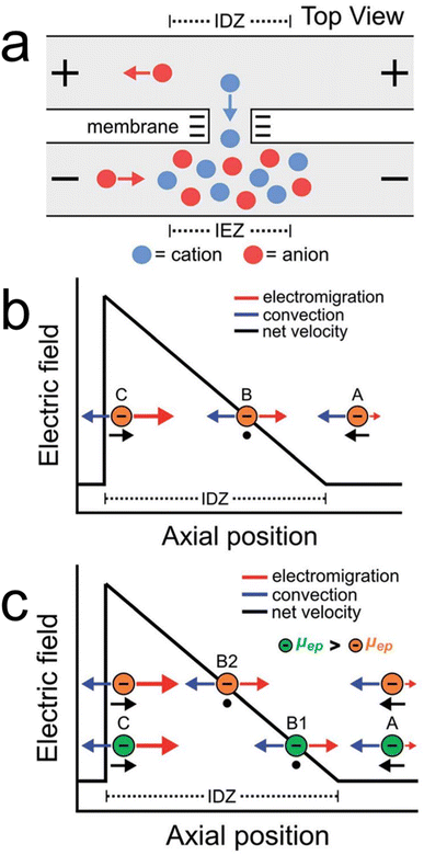
ICP is a popular route for forming electric field gradients within microfluidic devices.27–29 As illustrated in Scheme 1a, ICP occurs when a potential bias is applied across a charge-selective feature like a nanopore or nanoporous membrane material (e.g., Nafion). In this illustration, selective transport of cations across the charge-selective feature results in two regions: an ion enrichment zone (IEZ) and an ion depletion zone (IDZ) where ions are accumulated and depleted, respectively. Of interest to experimentalists is the ionic concentration gradient that forms between the IDZ and the bulk solution. In the presence of an electric field, the ionic concentration gradient gives rise to a co-located electric field gradient.As mentioned in the previous section, electric field gradients are useful for charge-based separations. Scheme 1b shows how an electric field gradient can be leveraged to control the motion of charged species in a single dimension. Specifically, consider the motion of an anion along an electric field gradient in the presence of uniform solution convection. At position A, where electromigration is low, the motion of the anion is dominated by convection and it moves from right-to-left. In contrast, at positions B and C, the electric field is higher than at position A. Thus, anions experience no net force at position B and are redirected from left-to-right when at position C. The net effect is enrichment of anions along the electric field gradient at position B.
By extrapolating the principles used when enriching a single analyte, more complex separations can be performed. For example, consider Scheme 1c, where two analytes (green and orange) with different electrophoretic mobilities (μep) are introduced. Because the electrophoretic mobilities of the analytes differ, the green and orange analytes enrich at different locations along the electric field gradient where their electromigration and convection are equal and opposite (positions B1 and B2 for the green and orange analytes, respectively). In this manner, given analytes with sufficiently different electrophoretic mobilities, multiple analytes can be enriched and separated along an electric field gradient.
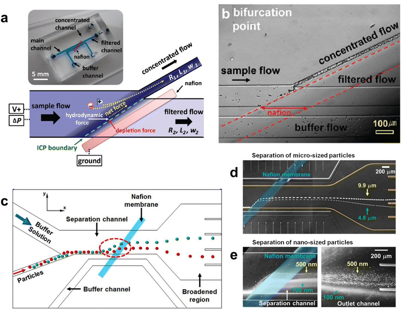
Beyond one-dimensional enrichment experiments, experiments can be designed for continuous separations. Consider Fig. 1a, which shows an image and schematic illustration of a device designed by Han and coworkers30 to utilize ICP for continuous separations. Here, a bifurcated microchannel is used with a Nafion membrane patterned near the channel bifurcation. When a voltage is applied as illustrated, an IDZ and accompanying electric field gradient (i.e., “ICP boundary” as denoted) evolve near the channel bifurcation to redirect charged species into the top outlet.
Fig. 1b is a micrograph showing the channel bifurcation in the same device during operation. Charged biological entities (i.e., bacteria and red blood cells) flow from left-to-right in the microchannel by solution convection. Upon encountering the IDZ and concomitant electric field gradient near the Nafion membrane, the biomolecules are continuously redirected and separated into the top outlet channel. This result confirms that ICP is useful for continuous separations and can be used to manipulate the motion of micron-sized entities.
Following the results described above, Lim and coworkers introduced the device shown in Fig. 1c.23 Here, flow focusing was used to introduce charged species into the bottom portion of the separation channel. From there, the charged species flow by solution convection in the x-direction until they encounter the Nafion membrane, where an IDZ and electric field gradient form perpendicular to solution flow (dashed red circle). Accordingly, the electric field gradient deflects ions to varying degrees in the y-direction based on their electrophoretic mobility. For example, as illustrated, the green particles have a higher mobility than the red particles and, thus, deflect further from the influent stream. Finally, after separating near the IDZ, particle populations are isolated in different outlet channels.
Fig. 1d and e show the experimental results that correspond with the device pictured in Fig. 1c. Fig. 1d shows the continuous separation of 4.8 μm and 9.9 μm microplastics. That is, due to their higher mobility, the 9.9 μm microplastics are deflected further by the IDZ and electric field gradient than the 4.8 μm microplastics. This makes it possible to collect the microplastic populations in different outlets. Fig. 1e shows an experiment similar to that in Fig. 1d, but in this case 500 nm and 100 nm microplastics are separated.
The foregoing experimental results represent a critical milestone in the development of an electrokinetic MP10 separation platform for two reasons. First, the findings demonstrate the efficacy of ICP for continuously separating microplastics on the basis of electrophoretic mobility. This is the crux of the perspective research discussed here. Second, the article highlights that ICP can target microplastics ranging in size from 9.9 μm down to 100 nm, which corresponds to MP10 and is essential for developing new and effective separation methods for studying the smallest microplastics.
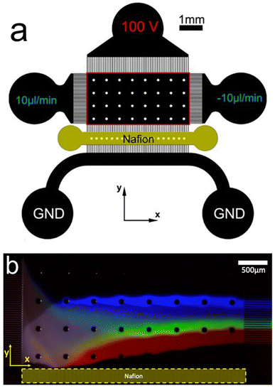
Fig. 2a shows a device configuration which is fundamentally similar to the one shown in Fig. 1c. That is, solution convection proceeds in the x-direction while an IDZ and electric field gradient form near a Nafion membrane in the y-direction. In this case, however, the targets of the separation experiments were fluorescent anionic dyes.31Fig. 2b is a fluorescence micrograph from a representative separation experiment using the device shown in Fig. 2a. Here, the anionic dyes are separated in the y-direction on the basis of their electrophoretic mobility and then isolated in downstream microchannels.
Separating anionic dyes in this manner emphasizes that ICP can be used to separate charged species, but, importantly, further demonstrates that the technique can target entities down to the molecular level. This means that ICP can target and separate entities spanning the entire size range of MP10. An additional point of significance from this work is that, while the authors demonstrated separation of the dyes, each dye is individually enriched up to 5-fold. The simultaneous and continuous separation and enrichment of analytes has important implications for improving detection limits when studying MP10. This point is particularly notable because microplastics are often present in low concentrations in water samples.15
Continuous separation of MP10 by ICP on a microfluidic device provides one additional benefit not yet discussed. Specifically, microfluidic platforms provide the opportunity to couple ICP with downstream detection methods like AC-dielectrophoresis, pyrolysis-gas chromatography, or flow cytometry.2 As such, ICP presents a potentially powerful approach to separating MP10 while offering a platform that can be integrated with other methods for the total analysis of microplastic samples.
Finally, while the benefits of ICP suggest that it is an excellent approach for separating and studying MP10, it is important to note some limitations. First, fabrication of microfluidic devices containing charge-selective features, such as Nafion, is not simple. This can limit device-to-device reproducibility, which would obviously detract from a standardized analysis technique. Second, charge-selective features are susceptible to clogging during operation. If debris, such as microplastics, obstruct the charge-selective feature, the device is rendered unusable. Accordingly, while ICP is a promising candidate for separating and studying MP10, it is logical to also consider electrokinetic approaches that function similarly to ICP but avoid using charge-selective features. Such alternative approaches are the focus of the next section.
Electrochemical approaches for separating microplastics
In 2008, our group developed an electrochemical variant of ICP to circumvent the challenges associated with charge-selective features.32 Specifically, we used bipolar electrochemistry to form IDZs and corresponding electric field gradients. While bipolar electrochemistry is not the focus of this perspective and has been previously reviewed by us33,34 and others,35,36 it is central to the following electrochemical separation methods and, thus, requires a brief introduction.A bipolar electrode (BPE) is an electrically isolated conductor immersed in an electrolyte-containing solution. As shown in Scheme 2, in the presence of an electric field, there is a potential difference between the two ends of the BPE and the solution (ηan and ηcat). If the potential difference between the BPE and solution (ΔEelec) is greater than the potential difference between available electrochemical reactions (e.g., ΔEelec > Ewaterreduction − Ewateroxidation), then concerted oxidation and reduction reactions will proceed at the ends of the BPE.
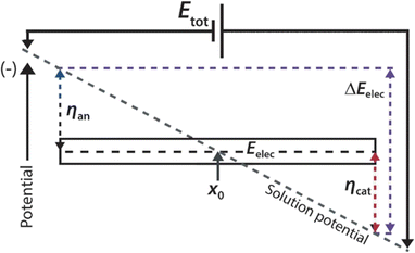 | ||
| Scheme 2 Schematic representation of the operation of a bipolar electrode. Adapted from: Angew. Chem., Int. Ed., 2013, 52, 10438–10456 (copyright © 2013 WILEY-VCH Verlag GmbH & Co. KGaA, Weinheim). | ||
Our group has leveraged bipolar electrochemistry in the presence of buffered solutions to form IDZs and concomitant electric field gradients. That is, given a sufficient electric field in solution, water oxidation (eqn (1)) and reduction (eqn (2)) proceed at either end of the BPE. The electrogenerated OH− at the BPE cathode neutralizes Tris buffer in solution to form a localized IDZ (eqn (3)).
BPE anode:
| 2H2O → 4H+ + 4e− + O2 | (1) |
BPE cathode:
| 2H2O + 2e− → 2OH− + H2 | (2) |
| TrisH+ + OH− → Tris + H2O | (3) |
Because electrochemistry is used to form an IEZ and an IDZ near the BPE anode and cathode, respectively, we termed the technique faradaic ion concentration polarization (fICP).37 Relying on electrochemical reactions, rather than simple mass transport as in traditional ICP, imparts two important characteristics to fICP. First, no charge-selective features (Scheme 1a) are necessary to form an IDZ, which avoids the previously discussed limitations of traditional ICP. Second, there is a threshold voltage associated with initiating electrochemical reactions at a BPE (e.g., no electrochemistry occurs if ΔEelec < Ewaterreduction − Ewateroxidation). Accordingly, fICP does not occur in the presence of small electric fields. This is in contrast to traditional ICP, which occurs in the presence of any applied voltage. Notably, due to this distinction, ICP and fICP have different control parameters.
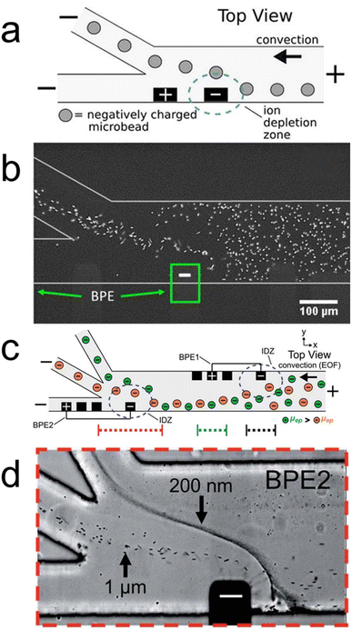
In recent years, we have designed fICP experiments to facilitate continuous MP10 separations.24,25 For example, Fig. 3a is a schematic illustration of a bifurcated microfluidic device with a BPE (black rectangles) directly upstream of the channel bifurcation. Fig. 3b is a fluorescence micrograph showing the channel bifurcation and BPE cathode of the device illustrated in Fig. 3a during operation. Here, electrochemical reactions at the BPE cathode form an IDZ (eqn (3)) and accompanying electric field gradient in buffered electrolyte solution. This IDZ redirects fluorescent microplastics into the top outlet channel, thereby highlighting the utility of fICP for continuously separating MP10.
Fig. 3c is a schematic illustration of a more complex microfluidic device than that shown in Fig. 3a. Here, the channel is trifurcated and two BPEs are present in the device. BPE 1 is significantly upstream of the channel trifurcation and is used to focus microplastics into the bottom portion of the channel. In this manner, the need for a separate flow focusing step (as in Fig. 1c) before continuously separating microplastics is eliminated. BPE 2 is placed immediately upstream of the channel trifurcation and deflects charged species in the y-direction on the basis of their mobility.
Fig. 3d is a micrograph of the device in Fig. 3c showing the channel trifurcation and the cathode of BPE 2 during a separation experiment. Here, the IDZ at BPE 2 deflects and continuously separates 1.0 μm and 200 nm microplastics into subpopulations on the basis of their electrophoretic mobility. The results shown in Fig. 3c and d are significant for the following three reasons. First, the results demonstrate that continuously separating microplastics on the basis of electrophoretic mobility is possible with fICP. Second, the findings show fICP is effective for targeting small microplastics well into the nano-scale regime, which is critical for new MP10 separation methods. Third, due to their wireless nature, BPEs offer a significant amount of experimental flexibility, even after device fabrication.24,25,33 In this case, leveraging two BPEs to simultaneously form multiple IDZs facilitates the continuous separation of MP10.
Fundamentally, fICP addresses the issues regarding charge-selective features that face traditional ICP while providing a high level of modularity during experiments. The application of fICP is, however, limited to buffered solutions where an IDZ and electric field gradient can be formed electrochemically. This constraint seriously limits the scope of fICP for practical separations in real solutions like drinking water and seawater.
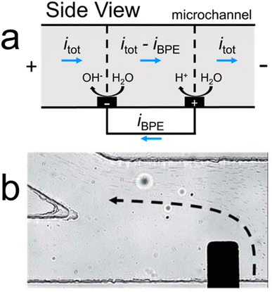
Accordingly, in addition to investigating fICP, our group has explored a buffer-free electrochemical approach for forming electric field gradients.26,38 In this method, rather than relying on an IDZ to vary the electric field in solution, electric field gradients are formed by taking advantage of the presence of the BPE. Specifically, as shown in Fig. 4a, electrochemical reactions at a BPE shunt electrical current away from the microchannel (iBPE), which modulates the ionic current passing through solution. These ionic current variations contribute to forming electric field gradients near the BPE poles.
Fig. 4b is a micrograph of a representative experiment in the buffer-free electrochemical system. Here, the BPE shunts electrical current away from the microchannel, forming an electric field gradient which continuously separates microplastics (microplastic trajectory outlined by the dashed black arrow). Leveraging ionic current gradients at BPEs in this manner, rather than electrochemically forming IDZs in buffered solution, is a promising approach to electrokinetically separating MP10 in solutions like drinking water and seawater. It is critical to note that, in the absence of buffer, water electrolysis at the BPE forms significant pH gradients. These pH gradients can affect microplastic surface properties and, therefore, may impact separation efficacy. Importantly, however, fICP and the buffer-free electrochemical system provide alternative electrokinetic approaches for separating MP10 with distinct advantages and limitations when compared with each other and traditional ICP.
Future outlook
Here, we have discussed key literature results which demonstrate the utility of electrokinetic approaches for separating MP10. Advantages of the foregoing electrokinetic approaches include the ability to continuously separate microplastics on the basis of their electrophoretic mobility, the capability to target the entire size range of MP10, and the implementation of the techniques in microfluidic devices. This latter point is important because it provides both portability for in-the-field sampling and the possibility to integrate downstream detection methods for a total analysis system.Of course, while electrokinetic methods are attractive for the above reasons, there remain four barriers to practical electrokinetic separation of MP10. First, while microfluidic platforms provide multiple benefits, they also limit throughput. Low throughput reduces the amount of microplastics sampled, which, in turn, can hinder detection limits. Increasing the throughput of microfluidic devices has been discussed or demonstrated using microfluidic arrays39,40 and out-of-plane channels,41,42 respectively, and incorporating such methods may be necessary for effectively studying MP10 samples. Alternatively, ultrasensitive detection methods, such as mass spectrometry, can be coupled to microfluidic devices to overcome the issue of low throughput.43,44
Second, the presence of ionic concentration gradients (IDZs and IEZs) and electric field gradients contribute to complex solution convection via electroosmotic flow (EOF).27,28 This complex convection results from non-linear EOF and can diminish separation efficacy. For example, while complex convection may not complicate relatively simple separations (e.g., one analyte from water), simultaneous separation of multiple analytes on the basis of their electrophoretic mobility was complicated by the presence of non-linear EOF.25 Introducing surfactants to limit or eliminate EOF can mitigate this issue.25,45,46
Third, the electrolyte concentration during experiments can significantly affect separation performance. This is because forming IDZs, as well as performing electrochemistry, is influenced by the background electrolyte concentration. The electrokinetic techniques discussed here work best in low electrolyte concentrations, but ICP,47 fICP,37 and the buffer-free electrochemical method38 are all operational in high electrolyte concentrations (>50 mM). Corresponding experimental results extending application of these techniques to MP10 separations in high ionic strength solutions remain to be demonstrated.
Fourth, regarding the electrochemical methods, ionic current gradients and electrogenerated ionic concentration gradients are not uniformly distributed throughout the height of the microchannel. This is because the electrodes used to induce separation are patterned on the microchannel floor. Integrating three-dimensional electrodes42 may improve the uniformity of electric field gradients throughout the microchannel height and improve separation utility.
Importantly, while these four points have been addressed independently, research in the field should focus on incorporating the solutions to each of these challenges into a single device for separating MP10. Moreover, beyond addressing these four fundamental points, there is another practical issue which needs to be resolved regarding electrokinetic separations: separating complex, real MP10 from environmental samples. That is, simultaneously separating three or more classes of microplastic analytes has not been experimentally demonstrated using continuous flow devices. Expanding experimental results to separating numerous analytes (>3) will mirror the complexity of real samples. Also, while we have highlighted that electrokinetic approaches can separate the gamut of MP10 sizes, separations concurrently targeting the entire size range of MP10 need to be demonstrated for practical applications.
Designing devices to this end is critical for effectively separating the smallest microplastics. Using device geometries similar to those shown in Fig. 1c and 2a will likely provide utility towards more complex separations. Fine tuning the electric field and solution convection in these devices will be key to broadening the scope of possible separations. Additionally, utilizing multiple electric field gradients may provide advantages for facilitating these complex separations. For example, multiple electric field gradients could enable greater resolution during separations (e.g., a two-stage separation) as well as the ability to enrich analytes before detection (Scheme 1b).
Finally, there is one last point to consider regarding real microplastic samples. Until now, reports utilizing electrokinetic approaches have separated monodisperse, lab-fabricated microplastic samples. In contrast, when separating microplastics from real environmental or biological samples, there is significantly more heterogeneity regarding plastic size, shape, and composition. This heterogeneity, in addition to adsorbed toxins or biofilms which can affect microplastic surface properties (e.g., surface charge), would ultimately impact the separation performance. Thus, there is an outstanding need for studies which investigate separating real microplastic samples in different matrixes using electrokinetic techniques. Understanding and dealing with the complexity of real samples will be key to unlocking the potential of electrokinetic methods as platforms for separating and studying microplastics.
Author contributions
JRT and RMC conceptualized the manuscript. JRT wrote the original draft of the manuscript. JRT and RMC edited the manuscript.Conflicts of interest
The authors state that there are no conflicts of interest.Acknowledgements
We gratefully acknowledge support from the Chemical Sciences, Geosciences, and Biosciences Division, Office of Basic Energy Sciences, Office of Science, U.S. Department of Energy (Grant: DE-FG02-06ER15758). We thank the Robert A. Welch Foundation (Grant F-0032) for sustained support of our research program. JRT acknowledges support from the Provost’s Graduate Excellence Fellowship.References
- A. Tirkey and L. S. B. Upadhyay, Mar. Pollut. Bull., 2021, 170, 112604 CrossRef CAS.
- K. Zhao, Y. Wei, J. Dong, P. Zhao, Y. Wang, X. Pan and J. Wang, Environ. Pollut., 2022, 297, 118773 CrossRef CAS.
- R. C. Thompson, Y. Olsen, R. P. Mitchell, A. Davis, S. J. Rowland, A. W. G. John, D. Mcgonigle and A. E. Russell, Science, 2004, 304, 838 CrossRef CAS PubMed.
- L. Cutroneo, A. Reboa, G. Besio, F. Borgogno, L. Canesi, S. Canuto, M. Dara, F. Enrile, I. Forioso, G. Greco, V. Lenoble, A. Malatesta, S. Mounier, M. Petrillo, R. Rovetta, A. Stocchino, J. Tesan, G. Vagge and M. Capello, Environ. Sci. Pollut. Res., 2020, 27, 8938–8952 CrossRef CAS PubMed.
- B. Xu, F. Liu, Z. Cryder, D. Huang, Z. Lu, Y. He, H. Wang, Z. Lu, P. C. Brookes, C. Tang, J. Gan and J. Xu, Crit. Rev. Environ. Sci. Technol., 2020, 50, 2175–2222 CrossRef CAS.
- Q. Zhang, E. G. Xu, J. Li, Q. Chen, L. Ma, E. Y. Zeng and H. Shi, Environ. Sci. Technol., 2020, 54, 3740–3751 CrossRef CAS PubMed.
- H. A. Leslie, M. J. M. van Velzen, S. H. Brandsma, A. D. Vethaak, J. Garcia-Vallejo and M. H. Lamoree, Environ. Int., 2022, 163, 107199 CrossRef CAS.
- L. C. Jenner, J. M. Rotchell, R. T. Bennett, M. Cowen, V. Tentzeris and L. R. Sadofsky, Sci. Total Environ., 2022, 831, 154907 CrossRef CAS PubMed.
- A. Alfaro-Núñez, D. Astorga, L. Cáceres-Farías, L. Bastidas, C. Soto Villegas, K. Macay and J. H. Christensen, Sci. Rep., 2021, 11, 6424 CrossRef.
- S. L. Wright and F. J. Kelly, Environ. Sci. Technol., 2017, 51, 6634–6647 CrossRef CAS PubMed.
- A. D. Vethaak and J. Legler, Science, 2021, 371, 672–674 CrossRef CAS PubMed.
- J. Gigault, H. El Hadri, B. Nguyen, B. Grassl, L. Rowenczyk, N. Tufenkji, S. Feng and M. Wiesner, Nat. Nanotechnol., 2021, 16, 501–507 CrossRef CAS PubMed.
- E. R. Zettler, T. J. Mincer and L. A. Amaral-Zettler, Environ. Sci. Technol., 2013, 47, 7137–7146 CrossRef CAS.
- United States Environmental Protection Agency, About Risk Assessment, accessed 2 June 2022, https://www.epa.gov/risk/about-risk-assessment Search PubMed.
- P. Marsden, B. Koelmans, J. Bourdon-Lacombe, T. Gouin, L. D'Anglada, D. Cunliffe, P. Jarvis, J. Fawell and J. De France, Microplastics in Drinking-Water, Geneva, 2019 Search PubMed.
- A. Cózar, F. Echevarría, J. I. González-Gordillo, X. Irigoien, B. Úbeda, S. Hernández-León, Á. T. Palma, S. Navarro, J. García-de-Lomas, A. Ruiz, M. L. Fernández-de-Puelles and C. M. Duarte, Proc. Natl. Acad. Sci. U. S. A., 2014, 111, 10239–10244 CrossRef.
- S. M. Mintenig, P. S. Bäuerlein, A. A. Koelmans, S. C. Dekker and A. P. Van Wezel, Environ. Sci.: Nano, 2018, 5, 1640–1649 RSC.
- M. Cole and T. S. Galloway, Environ. Sci. Technol., 2015, 49, 14625–14632 CrossRef CAS.
- T. S. Galloway, M. Cole and C. Lewis, Nat. Ecol. Evol., 2017, 1, 0116 CrossRef.
- I. Velzeboer, C. J. A. F. Kwadijk and A. A. Koelmans, Environ. Sci. Technol., 2014, 48, 4869–4876 CrossRef CAS.
- W. Fu, J. Min, W. Jiang, Y. Li and W. Zhang, Sci. Total Environ., 2020, 721, 137561 CrossRef CAS.
- M. Correia and K. Loeschner, Anal. Bioanal. Chem., 2018, 410, 5603–5615 CrossRef CAS.
- H. Jeon, H. Lee, K. H. Kang and G. Lim, Sci. Rep., 2013, 3, 3483 CrossRef.
- C. D. Davies, E. Yoon and R. M. Crooks, ChemElectroChem, 2018, 5, 877–884 CrossRef CAS.
- C. D. Davies and R. M. Crooks, Chem. Sci., 2020, 11, 5547–5558 RSC.
- J. R. Thompson, L. M. Wilder and R. M. Crooks, Chem. Sci., 2021, 12, 13744–13755 RSC.
- S. J. Kim, Y.-A. Song and J. Han, Chem. Soc. Rev., 2010, 39, 912–922 RSC.
- M. Li and R. K. Anand, Analyst, 2016, 141, 3496–3510 RSC.
- B. Berzina and R. K. Anand, Anal. Chim. Acta, 2020, 1128, 149–173 CrossRef CAS PubMed.
- R. Kwak, S. J. Kim and J. Han, Anal. Chem., 2011, 83, 7348–7355 CrossRef CAS.
- V. A. Papadimitriou, L. I. Segerink and J. C. T. Eijkel, Anal. Chem., 2020, 92, 4866–4874 CrossRef CAS PubMed.
- R. Dhopeshwarkar, D. Hlushkou, M. Nguyen, U. Tallarek and R. M. Crooks, J. Am. Chem. Soc., 2008, 130, 10480–10481 CrossRef CAS PubMed.
- S. E. Fosdick, K. N. Knust, K. Scida and R. M. Crooks, Angew. Chem., Int. Ed., 2013, 52, 10438–10456 CrossRef CAS PubMed.
- F. Mavré, R. K. Anand, D. R. Laws, K.-F. Chow, B.-Y. Chang, J. A. Crooks and R. M. Crooks, Anal. Chem., 2010, 82, 8766–8774 CrossRef.
- G. Loget, D. Zigah, L. Bouffier, N. Sojic and A. Kuhn, Acc. Chem. Res., 2013, 46, 2513–2523 CrossRef CAS.
- K. L. Rahn and R. K. Anand, Anal. Chem., 2021, 93, 103–123 CrossRef CAS PubMed.
- R. K. Anand, E. Sheridan, K. N. Knust and R. M. Crooks, Anal. Chem., 2011, 83, 2351–2358 CrossRef CAS PubMed.
- J. R. Thompson and R. M. Crooks, ChemElectroChem, 2022, 9, e202200251 CrossRef CAS.
- W. J. Jeong, J. Y. Kim, J. Choo, E. K. Lee, C. S. Han, D. J. Beebe, G. H. Seong and S. H. Lee, Langmuir, 2005, 21, 3738–3741 CrossRef CAS.
- A. J. Bard, Integrated Chemical Systems: A Chemical Approach to Nanotechnology, Baker Lecture Series, Wiley Interscience, 1994 Search PubMed.
- B. D. MacDonald, M. M. Gong, P. Zhang and D. Sinton, Lab Chip, 2014, 14, 681–685 RSC.
- B. Berzina, S. Kim, U. Peramune, K. Saurabh, B. Ganapathysubramanian and R. K. Anand, Lab Chip, 2022, 22, 573–583 RSC.
- W. Liu and Y. Zhu, Anal. Chim. Acta, 2020, 1113, 66–84 CrossRef CAS.
- Y. Pico and D. Barcelo, TrAC, Trends Anal. Chem., 2020, 130, 115964 CrossRef CAS.
- R. K. Anand, E. Sheridan, D. Hlushkou, U. Tallarek and R. M. Crooks, Lab Chip, 2011, 11, 518–527 RSC.
- E. Sheridan, D. Hlushkou, K. N. Knust, U. Tallarek and R. M. Crooks, Anal. Chem., 2012, 84, 7393–7399 CrossRef CAS PubMed.
- S. I. Han, D. Lee, H. Kim, Y. K. Yoo, C. Kim, J. Lee, K. H. Kim, H. Kim, D. Lee, K. S. Hwang, D. S. Yoon and J. H. Lee, Anal. Chem., 2019, 91, 10744–10749 CrossRef CAS.
| This journal is © The Royal Society of Chemistry 2022 |


