Synergistic doping and structural engineering over dendritic NiMoCu electrocatalyst enabling highly efficient hydrogen production†
Ruopeng
Li
a,
Yang
Yuan
a,
Haoliang
Gui
a,
Yaqi
Liu
a,
Haoyu
Li
a,
Yaqiang
Li
a,
Shizheng
Wen
c,
Anmin
Liu
 b,
Jinqiu
Zhang
a,
Peixia
Yang
 *a and
Maozhong
An
a
aMIIT Key Laboratory of Critical Materials Technology for New Energy Conversion and Storage, School of Chemistry and Chemical Engineering, Harbin Institute of Technology, 150001 Harbin, China. E-mail: yangpeixia@hit.edu.cn
bState Key Laboratory of Fine Chemicals, School of Chemical Engineering, Dalian University of Technology, Dalian, 116086, China
cSchool of Physics and Electronic Electrical Engineering, Huaiyin Normal University, Huai'an, 223300, China
First published on 16th September 2022
Abstract
The development of non-precious metal electrocatalysts with remarkable activity is a major objective for achieving high-efficiency hydrogen generation. Here, a trimetallic electrocatalyst with a dendritic nanostructure, which is denoted as NiMoCu-NF, was fabricated on nickel foam via a gas-template electrodeposition strategy. By virtue of the metallic doping and structural optimization, NiMoCu-NF exhibits superior HER electrocatalytic activity with an overpotential of 52 mV at 10 mA cm−2. Additionally, the NiMoCu-NF-derived nickel-based (oxy)hydroxide species in the oxidation operating state deliver considerable electrocatalytic urea oxidation reaction (UOR) performance to match the efficient H2 generation, with a low voltage of 1.54 V to realize overall electrolysis at 50 mA cm−2. Impressively, combined experimental and simulation analysis demonstrate that the NiMoCu-NF with a favorable 3D nanostructure feature effectively regulates the heterogeneous interface states, inducing a “Gas Microfluidic Pumping” (GMP) effect that improved electron–mass transfer properties to accelerate the electrocatalytic reaction kinetics of either the HER or UOR.
Introduction
Owing to its strengths of eco-friendliness and sustainability, alkaline water electrolysis is regarded as one of the mainstream strategies for future high-purity hydrogen production, but its practical application is limited by the high energy consumption due to the inherently slow reaction kinetics, which urgently need to be overcome.1–3 In this regard, significant efforts have been committed to develop electrocatalysts with the properties of low cost, high intrinsic activity and outstanding durability, especially to satisfy the requirements of the hydrogen evolution reaction (HER) as the core half-reaction.4,5 Among the desirable candidates, nickel-based metals/alloys have been regarded as potential electrocatalysts by virtue of their unique d-band electronic states for adjustable immediate hydrogen absorption/desorption behavior.6–8 Notably, exploiting the synergistic effect of heteroatom doping can allow effective tuning of the site electronic configuration, thereby enhancing the HER activity of Ni-based electrocatalysts, as well as providing bifunctionality.9–12 This feasible strategy has been illustrated widely in recent representative studies of such bimetallic cooperation (Ni–Mo and Ni–Cu), since the modulated d-band center position is beneficial for promoting both water dissociation (Vomler step) and hydrogen bonding (Heyrovsky or Tafel step).13–16 Moreover, it can be concluded that the rational construction of Ni–Mo–Cu trimetallic cooperation may further strengthen the analogous favourable influence in nickel-based electrocatalysts.On the other hand, general research efforts have been devoted to improving the intrinsic activity of sites; however, favorable heterogeneous electrode–solution–gas interface properties are of crucial importance for the expression of electrocatalytic activity, which is often overlooked.17–19 Typically, the interfacial electron–mass transfer process, which is a prerequisite during electrocatalytic reactions, determines the overall kinetics, and is directly affected by the heterogeneous microenvironment states.20–22 It can be speculated that the liquid infiltration and dynamic gas evolution-release behavior in the both the cathode and anode half-reactions of water electrolysis can be regulated by rationally designing the nanostructures of self-supported electrocatalysts based on the structural fluid effect. The optimization of the solid–liquid–gas compatible states contributes to the fully exploited electrocatalytic performance.
Enlightened by the above, here we designed and fabricated a ternary nickel–molybdenum–copper electrocatalyst on nickel foam (denoted as NiMoCu-NF) with a delicate dendritic nanostructure via a novel gas-template electrodeposition strategy. The trimetallic synergy for modulation of the electronic configuration enables the self-supported electrocatalyst NiMoCu-NF to exhibit superior alkaline HER activity, with an overpotential of only 52 mV at 10 mA cm−2. Supported by the anodic urea oxidation reaction (UOR, with a lower theoretical potential of 0.37 V vs. RHE than the oxygen evolution reaction), a symmetrical couple constructed by bifunctional NiMoCu-NF realizes alkaline urea electrolysis for high-efficiency hydrogen production, and is driven by a sustainable solar-powered system. Comprehensive characterizations illustrate that NiMoCu-NF maintains structural and compositional stability during the HER, while at the oxidative operating potential, nickel-based (oxy)hydroxide species can be derived as active contributors for efficient UOR. Importantly, we focused on exploring the correlation between the catalyst nanostructure and catalytic performance. Detailed experimental observations and stimulation analyses together demonstrated that the NiMoCu-NF, with its favorable 3D nanostructure, has an effective influence on the interfacial states during the heterogeneous HER and UOR processes. A gas microfluidic pumping (GMP) effect was proposed to illustrate the structure-directed gas release, and the flow field disturbance, which is enhanced by optimizing the nanostructure, could accelerate the interfacial electron–mass transfer performance, thereby boosting the electrocatalytic performance.
Experimental
Materials
The chemicals used in this work include NiSO4·6H2O (≥99.0%, Aladdin), NaMoO4·2H2O (≥99.0%, Aladdin), CuSO4·5H2O (≥99.0%, Aladdin), Na4P2O7·10H2O (≥99.0%, Aladdin), NH4Cl (≥99.0%, Aladdin), ultrapure water (>18.25 MΩ cm), C2H5OH (99.7%), acetone, hydrochloric acid (HCl, ≥99.0%), KOH (≥99.0%), Ni foam (NF, 99.8%), and platinum on carbon (20 wt% Pt/C). All reagents were directly used without further purification.Ultrasonic treatment of the nickel foam (NF) was carried out in deionized water, ethanol and acetone, respectively. Hydrochloric acid was then used to activate the nickel foam for 15 min to remove the oxide species. The electrolyte contained 160 g L−1 Na4P2O7·10H2O, 20 g L−1 NH4Cl, 50 g L−1 NiSO4·6H2O, 2 g L−1 CuSO4·5H2O, and 0.5 g L−1 NaMoO4·2H2O. The pH of the solution was adjusted to be slightly acidic (5.5) to ensure that the deposited layer was an alloy phase rather than an oxide/hydroxide phase. A two-electrode system was constructed in which NF was used as the working electrode, and titanium dioxide as the counter electrode. The deposition area was 1 × 1 cm−2, and the deposition was performed for 4 min with a current density of 2.5 A cm−2. Additionally, the plating solution was stirred at 500 rpm during the reaction.
Electrochemical measurements
All the electrochemical performance measurements were obtained using a CHI 660e Electrochemistry Workstation. In the standard three-electrode system, the working electrode was the deposited samples, and Pt foil and HgO/Hg were employed as the counter and reference electrode, respectively. All the polarization curves were measured by linear sweep voltammetry (LSV) at a scanning speed of 2 mV s−1. CV activation (scan rates: 20 mV s−1) in the same potential range was carried out before LSV. Electrochemical impedance spectroscopy (EIS) was conducted in the frequency range of 10−2 to 105 Hz under different potentials. Cyclic voltammetry (CV) was used to measure the capacitance of the working electrode in the range of 0 to 0.1 V (vs. RHE) at gradient scanning rates from 10 to 200 mV s−1, and the ECSA values were evaluated by Cdl/0.04.Characterization
Scanning electron microscopy (SEM, Hitachi S4800, 5 kV), transmission electron microscopy (TEM, JEM 2100, 200 kV) and X-ray diffraction (XRD, D/max 2550 V with Cu Kα radiation of λ = 1.541841 Å) were adopted to determine the morphology and crystal structure of the as-prepared samples. X-ray photoelectron spectroscopy (XPS, Thermo Escalab 250, C 1s peak at 284.5 eV, and monochromatic He I light source of 21.2 eV) was used to investigate the elemental composition and surface chemical states of the sample. In situ Raman analysis was performed in a self-made electrochemical cell with Hg/HgO as the reference electrode and Pt wire as the reference electrode; RENISHAW (excitation wavelength of 432 nm) was conducted to monitor the in situ reaction at different operating potentials.Theoretical simulation
All modelling was conducted in the Vienna Ab initio Simulation package (VASP), and the Perdew–Burke–Ernzerhof (PBE) exchange-correlation functional was utilized within the generalized gradient approximation. The vacuum layers were set at around 15 Å in the z-direction to avoid interaction between planes. The cut-off energy and the k-point mesh were set to 400 eV and 4 × 4 × 1, respectively. The geometry regulation for energy and force were defined as 0.02 eV Å−1 and 10−5 eV, respectively.COMSOL multiphysics simulation
Numerical simulation was carried out using COMSOL Multiphysics. A two-dimensional symmetric model was used, and the radius of the reaction area was set as 0.3 cm. The tertiary current distribution in the electrochemistry module together with bubble flow and laminar flow in the CFD module were coupled together to simulate the gas evolution process during the HER and UOR. The parameters, including the exchange current and charge transfer coefficient for the HER and UOR, were calculated from the Tafel curves from the electrochemical measurements. Details are shown in the ESI.†Results and discussion
A novel strategy for the preparation of the ternary NiMoCu solid solution is illustrated schematically in Fig. 1a, in which commercial Ni foam (NF) serves as a substrate and dendrite arrays are uniformly fabricated via one-step gas-templated electrodeposition. Under the high deposition current density, the inevitable hydrogen evolution side reaction is exploited as a dynamic template, resulting in the deposition of plating with a delicate three-dimensional nanostructure (Fig. S1†). The scanning electron microscopy (SEM) images in Fig. 1b and c show that the electrodeposition layer fully covered the substrate with a dendritic morphology, and the corresponding EDS analysis in Fig. S2† reveals the co-existence of Ni, Mo and Cu in NiMoCu-NF. Subsequently, the nanostructural characterization of the as-deposited NiMoCu sample was investigated using transmission electron microscopy (TEM). As shown in the HRTEM image in Fig. 1d and a well-defined interplanar spacing of 0.21 nm corresponding to the Ni (111) facets verifies the metallic phase distribution, and is consistent with the analysis of the selected area electron diffraction (SAED) patterns shown in Fig. 1e. Meanwhile, low-crystallinity phases with lattice mismatch and amorphous composition can be observed surrounding the Ni particle. These nanostructured properties suggest that the co-deposition process with the introduction of heteroatoms can form a defect-rich structure, which induces an increase in the active site density and contributes to improving the electrocatalytic activity. The corresponding high-angle annular dark field-scanning TEM (HAADF-STEM) image and the integrated elemental mapping (Fig. 1f–j) together show a dendrite-like monomer structure with a diameter of about 800 nm, as well as a homogeneous Ni, Mo, Cu and O distribution. Brunauer–Emmett–Teller (BET) experiments show that dendritic NiMoCu-NF has a high specific surface area of 0.277 m2 g−1. In consideration of the influence of the structural properties on the heterogeneous interfacial environment, the gas/liquid contact properties with the electrodes were characterized. The liquid contact angle and gas release angle images in Fig. S3† and Movie S1, S2† together show that NiMoCu-NF has a relatively small liquid contact angle (fast reaching 0°) compared to NF. Meanwhile, for the gas adsorption process in solution, NiMoCu-NF also exhibits a greater repulsion effect. The above phenomenon shows that the three-dimensional array structure of the coating improves the hydrophilicity and gas repellency. All the above characterizations together demonstrate the fabrication of NiMoCu-NF with a delicate nanostructure.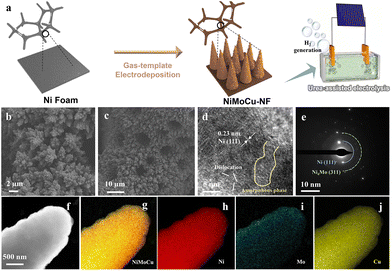 | ||
| Fig. 1 (a) Schematic illustration of the synthesis process for NiMoCu-NF. (b and c) SEM images. (d) HRTEM image. (e) SAED pattern. (f–j) HAADF-STEM image and the corresponding elemental mapping. | ||
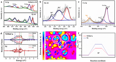
Next, XRD was performed on the as-prepared NiMoCu-NF to investigate the crystal patterns. As shown in Fig. S4,† three characteristic peaks appear at 44.2°, 51.4° and 75.8°, respectively, matching those of metallic nickel (JCPUS 04-0850), while the broad diffraction peaks reflect the low-crystallinity nature of the electrodeposited solid solution. X-ray photoelectron spectroscopy (XPS) was carried out to clarify the chemical composition and the coordination electron environment of NiMoCu-NF. Simultaneously, a dendritic Ni sample (labeled as Ni-NF) was prepared via the same electrodeposition processes for comparison (Fig. S5†). It can be seen in the survey spectrum in Fig. S6† that the Cu, Ni and O elements coexisted with a relatively higher Ni content ratio of 42.1% and Mo and Cu contents of 6.4% and 12.5%, respectively; these are slightly different than the ICP-MS results (Table S1†), which may be due to absorbed oxygen or superficial oxidation on the sample. The high-resolution Ni2p spectrum in Fig. 2b shows two peaks located at 856.3 and 874.1 eV corresponding to Ni 2p2/3 and Ni 2p1/2, respectively, while a characteristic Ni0 peak was identified at 852.8 eV, implying the existence of metallic phases. Obviously, the positive shift of the Ni 2p2/3 peak compared to that of Ni-NF indicates that the Mo and Cu co-doping regulates the electronic configuration.23,24 The Mo 3d spectrum in Fig. 2c was deconvoluted into Mo6+, Mo4+ and Mo0 states located at 235.7, 232.5 and 228.4 eV, respectively.25,26 For the Cu 2p spectra, the two peaks with binding energies of 934.4 and 932.1 eV were ascribed to the oxidation states Cu2+ and Cu+/Cu0, respectively.27 The above analysis clearly verifies the Mo and Cu co-doping with various species in solid solution. Based on the co-deposition mechanism in previous studies, molybdenum undergoes electro-reduction in a stable coordination environment at strong electrode polarization, thus resulting inevitably in the formation of molybdenum oxides at the interface. Fortunately, locally embedded oxidized components can modulate the adsorption of electrocatalytic intermediates to benefit the catalytic activity.28
In order to fully reveal the interaction between heteroatoms, DFT calculations were carried out for the intermetallic compound model. The calculated total density of states (TDOS) and particle density of states (PDOS) with the orbitals for different elements (Fig. 2d) were in line with the above XPS analyses, indicating that strong interactions between heteroatoms induce local electronic structure change, along with a moving d-band central from the Ni site (−1.47 eV) to the Cu site (−2.05 eV), which can be an effective site for weak adsorption. The corresponding HOMO and LUMO energy barriers in Fig. S7† demonstrate that the relatively lower value of the metallic NiMoCu model (ΔE = 0.07 eV) than that of Ni (ΔE = 0.11 eV) is beneficial for accelerating the charge transfer. The simulated electron density distribution presented in Fig. S8† and Fig. 2e exhibits the reduced electron density state on the active Ni site, as well as electron enrichment at the Cu and Mo sites, demonstrating the electron-pumping effect created by the doping of heteroatoms. The calculated adsorption/desorption capacities identify that the co-doping model effectively reduces the free energy of H* activation compared to the pristine Ni model, while clearly revealing the critical effect of interatomic synergy (Fig. 2f).29,30
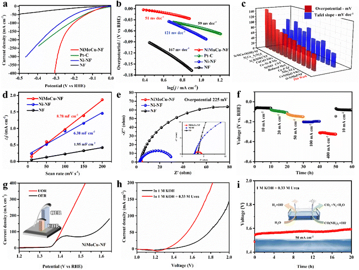
Based on the desirable catalytic potential of the as-prepared NiMoCu-NF, we then evaluated the HER electrocatalytic performance systemically. Linear sweep voltammetry measurements (LSV) were first carried out in a standard three-electrode system, and 20% commercial Pt/C and pure NF were employed for comparison. All the polarization curves measured in 1 M KOH solution are shown in Fig. 3a with 85% IR compensation. The HER electrocatalytic activity of NiMoCu-NF is significantly superior to those of Ni-NF and pure NF. The onset overpotential of NiMoCu-NF is close to 10 mV, and the overpotential required to deliver a current density of 10 mA cm−2 is 52 mV, which is comparable to that of commercially available Pt/C (37 mV) and Ni-NF (101 mV). Furthermore, NiMoCu-NF exhibits an overpotential of 305 mV when producing a high current density of 400 mA cm−2, demonstrating its potential under industrial-grade conditions. The calculated Tafel slopes in Fig. 3b show that NiMoCu-NF has a relatively lower value of 51 mV dec−1 compared to those of Pt/C (59 mV dec−1), Ni-NF (121 mV dec−1) and NF (167 mV dec−1), indicating that the catalytic process of NiMoCu-NF follows the Volmer–Heyrovsky process mechanism with enhanced intrinsic HER kinetics. We then changed the ratio of molybdenum and copper salts in the bath (NiMoCu-NF-2 denotes the high molybdenum salt group and NiMoCu-NF-3 the high copper salt group, as detailed in the ESI†). Although the morphology did not change significantly after the doping ratio adjustment, the HER activity was slightly inferior to that of NiMoCu-NF, indicating that the appropriate doping concentration is critical to the improvement of the HER activity (Fig. S9†). As shown in Fig. 3c and Table S2,† NiMoCu-NF exhibits competitive performance in comparison with representative electrocatalysts that have been reported recently.23,24,31–40
Further electrochemical measurements were performed to analyze the properties of the NiMoCu-NF catalyst comprehensively. The catalytic electrochemical surface area (ECSA) is also important to the catalytic HER performance, and is evaluated using the calculated double-layer capacitance (Cdl).41,42 The CV curves were measured using cyclic voltammetry under gradient scan rates (Fig. S10†), and the corresponding fitted Cdl results are shown in Fig. 3d. The calculated Cdl value of NiMoCu-NF is 8.78 mF cm−2, which is significantly higher than that of Ni-NF (6.38 mF cm−2) and pure NF (1.95 mF cm−2), indicating that the three-dimensional porous structure constructed via gas-templated electrodeposition effectively promotes the exposure of more active sites. Moreover, the ECSA normalized polarization curves in Fig. S10e† intuitively reveal enhanced intrinsic activity with Mo and Cu co-doping. Electrochemical impedance spectroscopy (EIS) measurements were then conducted at an operating voltage of 225 mV, and the Nyquist curves and corresponding fitting results are shown in Fig. 3e and Table S3.† Comparing the charge transfer resistance (Rct) values, the value of NiMoCu-NF (1.79 Ω) is obviously smaller than those of Ni-NF and NF, demonstrating that the HER process of NiMoCu-NF has fast electron transport and is weakly affected by mass transfer, which is especially crucial for high-current-density operation. Considering that the long-term durability of the electrocatalyst is an essential parameter for assessing its practical application, multi-step chronopotentiometry measurements with different current densities (10, 20, 50, 100 and 500 mA cm−2) were performed on NiMoCu-NF. As shown in Fig. 3f, the chronopotentiometry curves show that the sample underwent 60 h of operation without obvious attenuation. The faradaic efficiency (FE) yield of hydrogen evolution measured by gas chromatography (GC) technology was about 99% (Fig. S11†), confirming the high selectivity of the cathode reaction.
Next, NiMoCu-NF was investigated to explore the anodic electrocatalytic performance. Since the theoretical potential of the UOR (0.37 V) is lower than that of water oxidation (OER, 1.23 V), the alkaline urea-assisted system enables the NiMoCu-NF to participate in the anodic reaction with outstanding thermodynamic advantages. For NiMoCu-NF, as shown in Fig. 3g, the polarization curve of the UOR in 1 KOH + 0.33 M urea solution exhibits that only 1.40 V is needed to reach 100 mA cm−2, which is lower than the value of 1.57 V for the OER, suggesting improved thermodynamic properties. Owing to its desirable bifunctional activity, NiMoCu-NF is promising as a Janus electrocatalyst to participate in the construction of a two-electrode system to drive urea-assisted electrolysis for efficient hydrogen production. In Fig. 3h, the polarization curve of the NiMoCu-NF||NiMoCu-NF couple in the urea-assisted solution responds to an anodic current at 1.35 V, and only requires 1.54 V to produce a current density of 50 mA cm−2, which is significantly lower than the value of 1.77 V for water electrolysis, revealing significant energy savings brought about by upgrading the system. The overall stability was then evaluated by chronopotentiometry measurement. Under a current density of 50 mA cm−2, the alkaline urea-assisted electrolysis system retains good stability after 20 h of operation with negligible attenuation (Fig. 3i). Furthermore, a self-assembled solar-powered system was used to successfully drive the overall electrolysis process, demonstrating the potential for renewable energy conversion (Fig. S12 and Movie S3†).
Systematic characterizations were conducted to investigate the evolution of the structure and composition properties before and after the cathodic and anodic reactions. SEM images show that the morphological structural features of NiMoCu-NF that had undergone the HER remained basically unchanged, while typical hydroxide features appeared after the UOR, probably due to the oxidative reconstruction (Fig. S13†). The XPS analyses in Fig. 4a–c were used to study the surface chemical change after the HER and UOR tests. NiMoCu-NF clearly maintains compositional stability in terms of element distribution and valence characteristics. However, after the UOR, an obvious increase in in the oxidation states of Ni, Mo and Cu can be observed, along with a significant increase in the oxygen ratio (Fig. S14†). This phenomenon originates from the inevitable oxidation of the nickel-based species that may be associated with the UOR. To further reveal the oxidation behavior, in situ Raman analysis were performed on NiMoCu-NF in the oxidation faradaic potential range, as shown in Fig. 4d and Fig. S15.† In 1 M KOH, no obvious Raman peak was observed at the open circuit potential (OCP). As the operating potential increased to 1.35 V, the generated nickel species led to the emergence of Ni–O vibrations, corresponding to the appearance of oxidation peaks in the polarization curve. Subsequently, two broad peaks located at 471 and 554 cm−1 are significantly enhanced as the potential increases to 1.50 V; these peaks were attributed to the characteristic bending and stretching vibrations of Ni–O in nickel (oxy)hydroxides (y-NiOOH), directly demonstrating that NiOOH is abundantly reconstructed on the NiMoCu-NF surface. In Fig. S15b,† no Ni–O characteristic bonding can be detected in 1 M KOH + 0.33 M urea solution under the same operating conditions, indicating that active NiOOH species did not accumulate during the UOR. As analyzed in the previous representative study, y-NiOOH species are able to actively participate in the proton coupled electron transfer (PCET) step of the nucleophilic urea to act as active contributors to the UOR.43
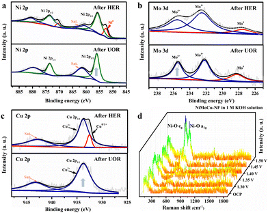 | ||
| Fig. 4 (a) High-resolution (a) Ni 2p (b) Mo 3d and (c) Cu 2p XPS spectra after the HER and UOR, respectively. (d) In situ Raman spectra of NiMoCu-NF under oxidizing conditions in 1 M KOH. | ||
Inspired by the superior electrocatalytic activity, we innovatively explored the structure-induced promotion mechanism of the catalyst. In consideration of the direct relationship between the electrode–electrolyte–gas microenvironment and the outgassing heterogeneous HER and UOR catalytic processes, the interfacial states affected by the structural characteristics of the self-supporting catalyst deserve in-depth elucidation. For this, we prepared flat-structured solid solution catalysts in the same system using a low deposition current density (labeled as l-NiMoCu-NF, Fig. S16†) in order to conduct a comparative study of the dendrite structure. The bubble desorption property was first investigated using the digital images in Fig. 5a and b. Under an operating potential of −0.2 V vs. RHE, it can clearly be seen that gas evolution occurred in both groups. The average bubble size produced from NiMoCu-NF is about 50 μm, which is significantly smaller than that of 130 μm for l-NiMoCu-NF. It can be illustrated that the favorable 3D structure ensures faster gas release behavior according to the Cassie–Baxter and Wenzel equations, which not only facilitates the exposure of active sites, but also helps to boost the electron–mass transfer locally. In order to monitor the dynamic states of the electrode–electrolyte interface during the electrolysis process, in situ EIS technology was then employed in the HER and UOR potential ranges. The comparison of the Nyquist curves of NiMoCu-NF and l-NiMoCu-NF in Fig. S17† shows that as the reaction driving potential increases, the change in the plots from linear to semicircular indicates that both undergo a transition from non-faradaic reaction to faradaic reaction with mass–electron-transfer hybrid control states, and that l-NiMoCu-NF is more relaxed. Since earlier studies have illustrated that nickel-based metal catalysts cannot form multiple interfaces with complex states, the measured phase angle values can be used to evaluate the mixed mass transfer and interfacial charge transfer processes intuitively.43 The corresponding Bode spectra in Fig. 5c and d show a linear change in the phase angles of the two groups during the HER and UOR processes, that is, a decrease with increasing reaction potential. Due to the intervention of structure changes, the smaller phase angle of NiMoCu-NF indicates that the optimized interface state achieves a faster reaction rate.
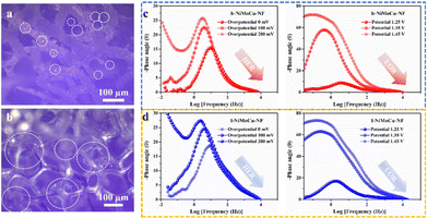 | ||
| Fig. 5 (a) Digital images of the gas release of (a) NiMoCu-NF and (b) l-NiMoCu-NF. (c and d) In situ Bode spectra of NiMoCu-NF and l-NiMoCu-NF under HER and UOR operating potentials, respectively. | ||
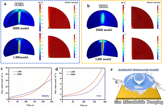
In the above analysis, the gas microfluidic pumping effect during the HER and UOR processes determines the heterogeneous interface microenvironment, which has a direct correlation with the structural characteristics of the electrocatalysts and the reaction rates, and merits systematic exploration. For this, we constructed a simulated electrode–solution–gas microenvironment model based on the experimental parameters to study the influences. As shown in the three-dimensional frame in Fig. 6a and b, the desorption processes after gas evolution are highly directional, which disturbs the solution to change the states of the solid–liquid interface, and the flow field caused by gas evolution will directly affect both mass transfer and charge transfer behavior. The flow rates of the low bubble radius (LBR) model are higher than those of the high bubble radius (HBR) model; the LBR model exhibits higher flow rates for both the HER and UOR processes, and the corresponding 2D spectra demonstrate that the flow field disturbance caused by the overflow of small-sized bubbles enables greater reactant distribution near the electrode. Additionally, the transfer rate of the HER process was simulated quantitatively, as shown in Fig. 6c. For 250 s of reaction, the transfer rate for the LBR model reached as high as 45 mol m−2 s−1, and was significantly higher than the values for the HBR model (32 mol m−2 s−1). Likewise, a similar phenomenon is observed in the simulation of UOR processes in Fig. 6d, in which the transfer rate of the LBR model is twice that of the HBR (6.2 mol m−2 s−1 compared to 3.8 mol m−2 s−1 at 150s). These results illustrate that non-directional flow field action leads to more rapid mass transfer, that is, more K(H2O)x+ reactants and urea enrichment during the reaction, coinciding with the above in situ EIS analysis. Additionally, the simulated electrocatalytic performance of the HER and UOR matches well with the experimental results (Fig. S18†). Based on the above analysis, we propose a novel gas microfluidic pumping effect (Fig. 6e), that is, the generation and desorption processes of small-sized bubbles occurring on the electrocatalysts with a dendritic nanostructure can effectively enhance both mass transfer and interfacial charge transfer capabilities during the heterogeneous reaction, thereby improving the catalytic performance.
Conclusions
In summary, the ternary nickel–molybdenum–copper electrocatalyst NiMoCu-NF with a dendritic morphology was prepared via a simple gas-template electrodeposition strategy. The metallic co-doping effect results in the optimized electron configuration of NiMoCu-NF, which promotes the intrinsic HER activity, while the surficial reconstruction to generate active nickel-based (oxy)hydroxides endows it with desirable UOR electrocatalytic performance. Encouragingly, an integrated couple fabricated using the bifunctional NiMoCu-NF and driven by a solar-powered system succeeded in efficient urea electrolysis for sustainable hydrogen production. Moreover, we conducted in-depth studies to demonstrate the critical impact of the favorable 3D nanostructure on catalytic performance, in which faster gas release processes can regulate the interfacial states during the heterogeneous HER and UOR reactions, inducing a “gas microfluidic pumping” effect that facilitates the interfacial electron and mass transfer, thus enhancing the reaction kinetics of both the HER and UOR.Conflicts of interest
There are no conflicts to declare.Acknowledgements
The authors gratefully acknowledge financial support from the National Natural Science Foundation of China (Grant No. 21878061). Numerical computations were performed at Hefei Advanced Computing Center. The authors would like to thank the Shiyanjia Lab (https://www.shiyanjia.com) for the XPS measurement.References
- M. Ball and M. Wietschel, Int. J. Hydrogen Energy, 2009, 34, 615–627 CrossRef CAS.
- J. Brauns and T. Turek, Processes, 2020, 8, 248 CrossRef CAS.
- K. Mazloomi and C. Gomes, Renewable Sustainable Energy Rev., 2012, 16, 3024–3033 CrossRef CAS.
- H. Sun, Z. Yan, F. Liu, W. Xu, F. Cheng and J. Chen, Adv. Mater., 2020, 32, 1806326 CrossRef CAS PubMed.
- X. Zou and Y. Zhang, Chem. Soc. Rev., 2015, 44, 5148–5180 RSC.
- R. Li, Y. Li, P. Yang, P. Ren, D. Wang, X. Lu, R. Xu, Y. Li, J. Xue, J. Zhang, M. An, J. Ma, B. Wang, H. Liu and S. Dou, Appl. Catal., B, 2022, 318, 121834 CrossRef CAS.
- A. Nairan, P. Zou, C. Liang, J. Liu, D. Wu, P. Liu and C. Yang, Adv. Funct. Mater., 2019, 29, 1903747 CrossRef CAS.
- R. Q. Yao, Y. T. Zhou, H. Shi, W. B. Wan, Q. H. Zhang, L. Gu, Y. F. Zhu, Z. Wen, X. Y. Lang and Q. Jiang, Adv. Funct. Mater., 2021, 31, 2009613 CrossRef CAS.
- Z. Jia, T. Yang, L. Sun, Y. Zhao, W. Li, J. Luan, F. Lyu, L. C. Zhang, J. J. Kruzic, J. J. Kai, J. C. Huang, J. Lu and C. T. Liu, Adv. Mater., 2020, 32, e2000385 CrossRef PubMed.
- R. Li, Y. Li, P. Yang, D. Wang, H. Xu, B. Wang, F. Meng, J. Zhang and M. An, J. Energy Chem., 2021, 57, 547–566 CrossRef.
- Y. Li, X. Tan, W. Yang, X. Bo, Z. Su, T. Zhao, S. C. Smith and C. Zhao, Cell Rep. Phys. Sci., 2020, 1(12), 100275 CrossRef CAS.
- X. Wang, Y. Tuo, Y. Zhou, D. Wang, S. Wang and J. Zhang, Chem. Eng. J., 2021, 403, 126297 CrossRef CAS.
- M. A. Ahsan, A. R. Puente Santiago, Y. Hong, N. Zhang, M. Cano, E. Rodriguez-Castellon, L. Echegoyen, S. T. Sreenivasan and J. C. Noveron, J. Am. Chem. Soc., 2020, 142, 14688–14701 CrossRef CAS PubMed.
- W. Du, Y. Shi, W. Zhou, Y. Yu and B. Zhang, Angew. Chem., Int. Ed. Engl., 2021, 60, 7051–7055 CrossRef CAS.
- J. Hou, Y. Sun, Z. Li, B. Zhang, S. Cao, Y. Wu, Z. Gao and L. Sun, Adv. Funct. Mater., 2018, 28, 1803278 CrossRef.
- Y. Wang, Y. Sun, F. Yan, C. Zhu, P. Gao, X. Zhang and Y. Chen, J. Mater. Chem. A, 2018, 6, 8479–8487 RSC.
- F. Y. Gao, S. J. Hu, X. L. Zhang, Y. R. Zheng, H. J. Wang, Z. Z. Niu, P. P. Yang, R. C. Bao, T. Ma, Z. Dang, Y. Guan, X. S. Zheng, X. Zheng, J. F. Zhu, M. R. Gao and S. H. Yu, Angew. Chem., Int. Ed. Engl., 2020, 59, 8706–8712 CrossRef CAS PubMed.
- H. Li, C. Cai, Q. Wang, S. Chen, J. Fu, B. Liu, Q. Hu, K. Hu, H. Li, J. Hu, Q. Liu, S. Chen and M. Liu, Chem. Eng. J., 2022, 435, 134860 CrossRef CAS.
- H. Liu, X. Li, L. Chen, X. Zhu, P. Dong, M. O. L. Chee, M. Ye, Y. Guo and J. Shen, Adv. Funct. Mater., 2021, 32, 2107308 CrossRef.
- J. Hu, A. Al-Salihy, J. Wang, X. Li, Y. Fu, Z. Li, X. Han, B. Song and P. Xu, Adv. Sci., 2021, 8, e2103314 CrossRef.
- R. Li, H. Xu, P. Yang, D. Wang, Y. Li, L. Xiao, X. Lu, B. Wang, J. Zhang and M. An, Nano-Micro Lett., 2021, 13, 120 CrossRef CAS.
- P. Liu, B. Chen, C. Liang, W. Yao, Y. Cui, S. Hu, P. Zou, H. Zhang, H. J. Fan and C. Yang, Adv. Mater., 2021, 33, e2007377 CrossRef PubMed.
- X. Chen, Z. Yu, L. Wei, Z. Zhou, S. Zhai, J. Chen, Y. Wang, Q. Huang, H. E. Karahan, X. Liao and Y. Chen, J. Mater. Chem. A, 2019, 7, 764–774 RSC.
- M. Sheng, Q. Wu, Y. Wang, F. Liao, Q. Zhou, J. Hou and W. Weng, Electrochem. Commun., 2018, 93, 104–108 CrossRef CAS.
- L. Huang, F. Z. Yang, S. G. Sun, S. K. Xu and S. M. Zhou, Chin. J. Chem., 2003, 21, 382–386 CAS.
- L. Huang, F. Z. Yang, S. K. Xu and S. M. Zhou, Trans. Inst. Met. Finish., 2001, 79, 136–139 CrossRef CAS.
- Y. Zhao, J. Zhang, W. S. Zhang and A. L. Wu, Int. J. Hydrogen Energy, 2021, 46, 35550–35558 CrossRef CAS.
- L. Ribić-Zelenović, L. Rafailović, M. Spasojević and A. Maričić, Phys. B: Condens. Matter, 2008, 403, 2148–2154 CrossRef.
- W. Qi, W. Huang, J. Niu, B. Zhang, Z. Zhang and W. Li, Appl. Surf. Sci., 2021, 540, 148319 CrossRef.
- Z. Lyu, X. Zhang, X. Liao, K. Liu, H. Huang, J. Cai, Q. Kuang, Z. Xie and S. Xie, ACS Catal., 2022, 12, 5305–5315 CrossRef CAS.
- M. A. R. Anjum, H. Y. Jeong, M. H. Lee, H. S. Shin and J. S. Lee, Adv. Mater., 2018, 30, 1707105 CrossRef PubMed.
- M. Gong, W. Zhou, M.-C. Tsai, J. Zhou, M. Guan, M.-C. Lin, B. Zhang, Y. Hu, D.-Y. Wang, J. Yang, S. J. Pennycook, B.-J. Hwang and H. Dai, Nat. Commun., 2014, 5, 4695 CrossRef CAS.
- H. Jiang, M. Sun, S. Wu, B. Huang, C.-S. Lee and W. Zhang, Adv. Funct. Mater., 2021, 31, 2104951 CrossRef CAS.
- M. Kuang, P. Han, Q. Wang, J. Li and G. Zheng, Adv. Funct. Mater., 2016, 26, 8555–8561 CrossRef CAS.
- B. Ren, D. Li, Q. Jin, H. Cui and C. Wang, Chemelectrochem, 2019, 6, 413–420 CrossRef CAS.
- M. Song, Z. Zhang, Q. Li, W. Jin, Z. Wu, G. Fu and X. Liu, J. Mater. Chem. A, 2019, 7, 3697–3703 RSC.
- X. Teng, J. Wang, L. Ji, Y. Lv and Z. Chen, Nanoscale, 2018, 10, 9276–9285 RSC.
- T. Wang, Q. Zhou, X. Wang, J. Zheng and X. Li, J. Mater. Chem. A, 2015, 3, 16435–16439 RSC.
- D. Wei, W. Tang and Y. Wang, Int. J. Hydrogen Energy, 2021, 46, 20950–20960 CrossRef CAS.
- Y. Wu, Y. Liu, G.-D. Li, X. Zou, X. Lian, D. Wang, L. Sun, T. Asefa and X. Zou, Nano Energy, 2017, 35, 161–170 CrossRef CAS.
- G.-F. Chen, T. Y. Ma, Z.-Q. Liu, N. Li, Y.-Z. Su, K. Davey and S.-Z. Qiao, Adv. Funct. Mater., 2016, 26, 3314–3323 CrossRef CAS.
- Z. Huang, Z. Chen, Z. Chen, C. Lv, M. G. Humphrey and C. Zhang, Nano Energy, 2014, 9, 373–382 CrossRef CAS.
- N. Zhang, Y. Zou, L. Tao, W. Chen, L. Zhou, Z. Liu, B. Zhou, G. Huang, H. Lin and S. Wang, Angew. Chem., Int. Ed. Engl., 2019, 58, 15895–15903 CrossRef CAS.
Footnote |
| † Electronic supplementary information (ESI) available: Additional SEM, TEM, XRD, XPS, DFT results et al. See DOI: https://doi.org/10.1039/d2nr03984b |
| This journal is © The Royal Society of Chemistry 2022 |

