 Open Access Article
Recent progress and prospect of electrodeposition-type catalysts in carbon dioxide reduction utilizations
Ming
Miao
,
Haotian
Duan
,
Jiayao
Luo
and
Xin
Wang
 *
*
College of Chemistry, Zhengzhou University, Zhengzhou 450001, P. R. China. E-mail: wangxin0620@zzu.edu.cn
First published on 28th July 2022
Abstract
In recent years, electrocatalytic reduction of CO2 has been a focus in the research field. There are also various methods for synthesizing catalysts, such as the hydrothermal method, the arc method, electrospinning, etc. Here, we introduce the electrochemical deposition method. Compared with ordinary synthesis methods, electrodeposition has the advantages of simple processing, controllable conditions, high safety, and environmental friendliness. It is also a promising method for industrialized catalyst synthesis. In this review, we give a detailed introduction to electrodeposition, summarize the research progress of electrodeposition in the synthesis of catalysts, and discuss the key conditions in the preparation process, which are provided as a reference to synthesize next-generation electrodeposited electrocatalysts.
1. Introduction
With the intensification of human activities, the emission of CO2 has gradually become one of the dilemmas faced by human beings. The massive emission of CO2 leads to serious climate and environmental crises, such as the greenhouse effect and sea level rise.1 Recently, the conversion of CO2 into high value-added chemicals, thus alleviating energy problems and solving environmental problems, has been of wide concern. Various energy conversion and storage methods have been proposed, such as photocatalysis,2 electrocatalysis,3 metal–CO2 batteries,4etc. Among them, electrocatalysis is attracting more and more attention due to its high selectivity and energy utilization. Under the combined action of electricity and a catalyst, CO2 can be converted into a series of high value-added products, such as CO,5–7 formic acid,8,9 methane,10 ethylene,11 and ethanol.12 Researchers are also working on reducing CO2 to C3–C4 products.13 Therefore, the selection of catalysts is particularly important for the carbon dioxide reduction reactions (CDRRs).In order to improve the conversion efficiency of catalysts, the synthesis method plays a crucial role in controlling the structure and performance of electrocatalysts. Recently, various methods for synthesizing catalysts have also been developed by researchers, such as the hydrothermal method,14 the impregnation method,15etc. Although the catalysts synthesized by these synthetic methods have the advantages of large specific surface area and less agglomeration, there are also many limitations. These synthetic methods often require harsh environments, additional surfactants or capping agents, and high temperature conditions. The morphology and microstructure of nanomaterials cannot be easily and finely controlled. Moreover, the generated waste is highly toxic, and the mixture of pollutants and catalysts affects their long-term catalytic activity. In this context, electrodeposition is a promising alternative method for catalyst preparation. Electrodeposition has the following advantages: (1) fine control of electrodeposition can yield catalysts strongly bonded to the substrate with good homogeneity. For example, electrodes, current density, voltage, electrolyte composition, etc. can be easily regulated. (2) Morphologically controlled nanostructures can be prepared. (3) The deposition conditions are convenient and the operation is simple. However, electrodeposition also presents significant challenges, namely, the large experimental parameter space and the influence of the substrate on the morphology and chemical composition of the catalyst.
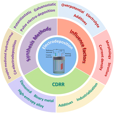
In this review, we introduce the recent progress of electrodeposition in the synthesis of catalysts in the CDRRs. Fig. 1 shows the main topics of this review. Various electrodeposition methods, including potentiostatic deposition, galvanostatic deposition and co-deposition, are discussed. And their advantages and challenges in CDRR applications are also discussed. In addition, we also discussed the influence of experimental parameters on the synthesis of the catalyst, including the deposition time, pH, additives and other factors. Finally, the research, challenges and future prospects of electrodeposition methods in the CDRRs are described.
2. Brief description of electrodeposition
2.1 Principle of electrodeposition
Electrodeposition typically occurs in a three-electrode system in which a metal electrode is immersed in a specific electrolyte solution and an electric field is applied to deposit the desired substance. Specifically, the first step is to reduce cations on the substrate surface to form adsorption atoms, which migrate to energy-favorable sites. Atoms deposited at other sites then cluster on the previous particles, forming the nucleus of the new phase. These nuclei will grow in different dimensions finally, and it is clear that many nuclei will form on the surface of the matrix. When a monolayer is formed on the surface of the substrate, electrodeposition takes place on this monolayer instead of the original substrate. It can be expected that the first layer of deposition formed will have a decisive influence on the morphology and structure of the following electrodeposition. Electrodeposition technology has many applications in the field of catalysis, ranging from deposition of single metals to alloys,16,17 metal oxides18,19 and even high entropy alloys.202.2 Apparatus for electrodeposition
Electrodeposition is generally carried out in a three-electrode system. A reference electrode is introduced into the conventional two-electrode system (working electrode and opposite electrode) to stabilize the working electrode. Therefore, the control and measurement of current and potential can be realized simultaneously in the three-electrode system. The device mainly includes the following three parts: the working electrode, counter electrode, and reference electrode. To be specific, the electrodeposition process and the subsequent electrocatalytic reaction take place at the working electrode, which possesses excellent electrical conductivity and chemical inertness. A polarization circuit is formed between the counter electrode and the working electrode to make the current on the working electrode unblocked. The potential of the counter electrode will change with the change of current. Therefore, a reference electrode is needed to ensure the accuracy of the test. The ideal reference electrode has some characteristics:21 (1) electrode reaction is reversible and conforms to the Nernst equation; (2) electric potential does not change with time; and (3) it is able to remain stable when a tiny current is passed, and is insensitive to temperature and other factors.3. Electrodeposition method
Electrochemical reduction of carbon dioxide is a promising method, which depends on the morphology, surface composition and structural characteristics of the catalyst. In recent years, researchers have made many explorations to design catalysts with high selectivity, high activity and excellent stability. Catalysts with various morphologies have also been reported, such as foam, thin film, dendrite, plate, crystal, etc. In this chapter, we will discuss in detail the method of preparing the catalyst by electrodeposition.3.1 Galvanostatic electrodeposition
In galvanostatic deposition the current is kept constant and the thickness and morphology of catalyst deposition is controlled by controlling the current density and deposition time. Fig. 2a shows a schematic diagram of one-step deposition of a nanocrystalline bismuth electrode with a constant current in a two-electrode system.22 Chen et al. used stainless steel as the counter electrode, polycrystalline copper foil as the working electrode, and a bath of 10 mM Bi3+ in 0.2 M NO3−. At 15 mA cm−2, the morphology and deposition thickness of the catalyst were optimized by controlling the deposition time. Nano-Bi branches were initially formed on the surface of the matrix after deposition for 500 s, and sharp spiniform secondary structures were formed at 800 s and 1200 s. When the deposition time was extended to 1500 s, the branches formed into grains, and Bi-agglomerated films were obtained. The Bi film electrode deposited at 1200 s exhibits high formate selectivity at −1.5 V (vs. Ag/AgCl), with a faradaic efficiency (FE) of 97.5%, and remains above 90% after 108 h of operation. Its excellent selectivity and stability are closely related to its spiny structure.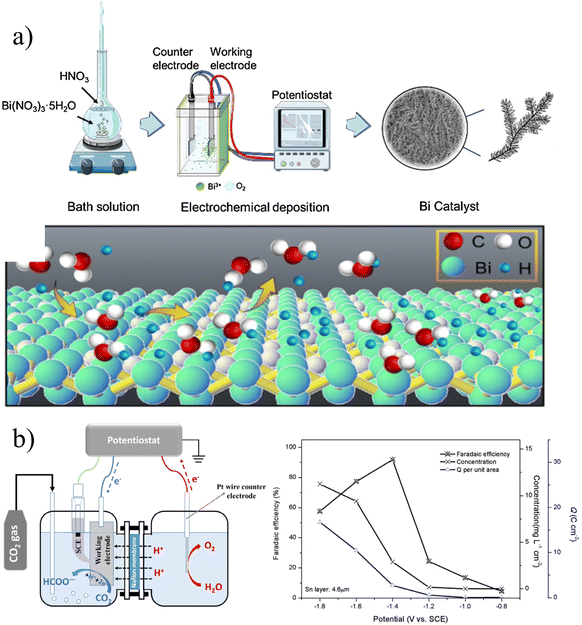 | ||
| Fig. 2 (a) Schematic diagram of the two-electrode system for constant current deposition of bismuth electrodes. Reproduced with permission.22 Copyright 2021, Elsevier. (b) Schematic diagram of electrocatalytic reduction of carbon dioxide in a three-electrode system and a summary of its performance. Reproduced with permission.23 Copyright 2016, Elsevier. | ||
In galvanostatic deposition, time and current are the two most important variables. Wang et al. deposited Sn on copper foil by controlling for a change in current density over the same deposition time (Fig. 2b).23 The catalyst was deposited at current densities of 5, 10, 15 and 20 mA cm−2 at a controlled deposition time of 10 min. At a current density of 5 mA cm−2, the small current density is not enough to deposit enough Sn to cover the matrix. For current densities of 10 and 15 mA cm−2, this system is suitable to create fine and compact particles. As for the current density of 20 mA cm−2, due to the serious hydrogen evolution reaction, the structure of the prepared catalyst is relatively loose and forms a columnar shape. It can be seen that the electrodeposition parameters can significantly control the morphology of the catalyst, resulting in the formation of dendritic, granular, columnar and other morphologies.
3.2 Potentiostatic electrodeposition
Potentiostatic deposition is a method of applying a constant potential deposition for a certain period of time during the electrodeposition process. Scholten et al. deposited nano-dendrite copper on Ag foil and Pt foil, respectively.24 Electrodeposition was completed by applying a voltage of −1.25 V (vs. reversible hydrogen electrode, RHE) in 0.05 M CuSO4. What is more interesting is that they treated the substrate with oxygen plasma for different periods of time, which increased the surface roughness. The substrate treatment not only affects the morphology of the deposition, but also inhibits the hydrogen evolution reaction.In the three-electrode system, the potential can be better controlled to adjust the morphology, surface structure and other properties of the catalyst, so as to obtain the most ideal catalyst. He et al. reported the synthesis of CuxAuy NWAs (nanowire arrays) in different proportions (i.e., CuAu, Cu3Au, and CuAu3) by the potentiostatic pulse electrodeposition method.25 The optimized CuxAuy NWAs showed high ethanol selectivity, with the FE of ethanol up to 45% at −0.7 VRHE. They controlled the atomic ratio by electrodeposition potential and further regulated the surface electronic structure of the catalyst. They found that during the CDRR process, due to the dense nanoarrays, the diffusion of OH− and *CO was restricted, resulting in higher local pH and *CO concentration on the nanowire surface, thus facilitating ethanol production.
The morphology and catalytic performance of the materials prepared using different electrodeposition methods are also divergent. Zhao et al. prepared hexagonal Bi sheets on copper foil by electrodeposition.26 The Bi film was deposited on a Cu substrate by the potentiostatic method, direct current electrodeposition method and pulse electrodeposition method, respectively. When the total charge passed is 20C, the deposition terminates. As shown in Fig. 3b, they prepared hexagonal, cubic and dendritic catalysts by different electrodeposition methods, respectively. The study showed that Bi slices prepared at a constant potential contained a large number of sharp edges and corners, which could improve the local electric field intensity and promote the rapid transfer of electrons. When the overpotential is −0.65 V, the FE of formate is close to 100%, and the yield is 96.37 μmol h−1 cm−2.
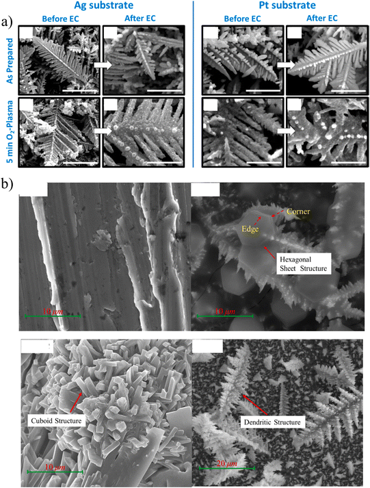 | ||
| Fig. 3 (a) Scanning electron microscopy (SEM) images of catalysts prepared under different conditions before and after the CDRR reaction. Reproduced with permission.24 Copyright 2019, American Chemical Society. (b) SEM images of copper and deposits of Bi obtained by different electrodeposition methods: constant potential, CP; direct current, DC; and pulse current, PC. Reproduced with permission.26 Copyright 2021, Elsevier. | ||
3.3 Co-electrodeposition method
Co-electrodeposition is generally used to deposit two or more metals for porous nanomaterials. By controlling the composition of precursors, deposition potential and other conditions, it is easy to control the deposition thickness and composition. Fontecave et al. report on a porous dendritic Ag–Zn alloy catalyst with an ultra-high specific surface area prepared by co-deposition (Fig. 4a).27 The combination of Ag and Zn produces a highly CO biased catalytic environment, showing a faradaic efficiency of more than 91% and no significant loss of selectivity at 40 h (FECO > 90%). As shown in Fig. 4b, Wang et al. prepared Cu–Sn alloys by co-electrodeposition in a three-electrode system.28 The electrodeposition solution contained 0.2 mol L−1 SnSO4 and 1.5 mol L−1 H2SO4. Before electrodeposition, the pretreated foam Cu was immersed in the electrolyte to obtain its own source of Cu2+ ions. The catalyst was obtained by applying a constant current of 4.0 mA cm−2 at 0.01–60 s on the electrode. The catalyst has a large active surface area, which is one of the reasons for its superior selectivity to formate.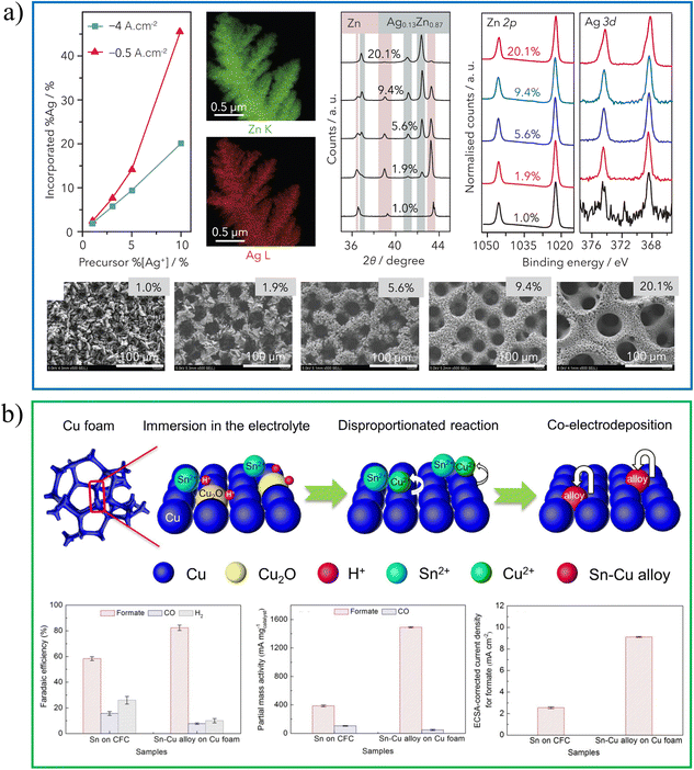 | ||
| Fig. 4 (a) Ag–Zn alloy growth and characterization. Reproduced with permission.27 Copyright 2020, Elsevier Inc. (b) Schematic diagram of SnCu alloy preparation and catalytic performance. Reproduced with permission.28 Copyright 2020, Elsevier. | ||
3.4 Pulse electrodeposition method
Pulse electrodeposition has pulse conduction time and pulse off time. During pulsed electrodeposition, the deposition ions consumed at the cathode–solution interface can be replenished within the pulse interval. Therefore, a higher peak of current density can be used to obtain smaller nanomaterials. Lee et al. deposited Bi catalyst with a nanosheet structure on copper foil by the pulse electrodeposition method.29 Bi nanosheet has more edges and corners, which is conducive to the generation of a local strong electric field and the highly selective production of HCOOH. Fig. 5 shows the Bi catalyst deposited under DC and pulse conditions, respectively. Some Bi particles were formed on the Cu substrate by DC deposition for 60 s, while the nanostructure changed to the dendritic form by DC deposition for 120 s. On the other hand, the nanosheet structure was formed by 6 times repeated pulse electrodeposition. A series of catalysts with different morphologies can be synthesized by pulse electrodeposition with different pulse periods and current densities.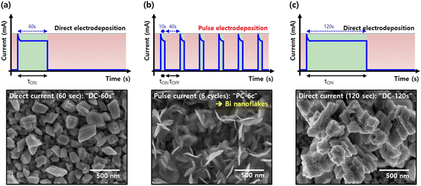 | ||
| Fig. 5 Current curves and the corresponding SEM images of direct electrodeposition and pulse electrodeposition. Reproduced with permission.29 Copyright 2017, Elsevier. | ||
Pulse electrodeposition can yield catalysts with special structures by controlling the parameters. For example, Yu et al. designed a Cu–Pd heterostructure,30 and they synthesized the CuCl–PdOx precursor by double-potential pulsed electrodeposition. The treated electrode was reduced at −1.6 V (vs. Ag/AgCl) for 100 s to obtain Cu–Pd heterojunction. The catalyst has a unique selectivity for CH4 with an FE of 32%. Furthermore, Zhang et al. provided a new strategy for the preparation of highly (111) textured nanotwinned copper (nt-Cu) by medium-frequency pulse electrodeposition.31 The effect of Cu2+ concentration on the structure was discussed in detail. A simple and robust method for the future large-scale preparation of (111) nt-Cu is also proposed.
3.5 Hydrothermal deposition and droplet mediated control of microstructure
There are also some more stringent conditions in the electrodeposition methods to meet special requirements. Researchers have done a lot of work to control the size and morphology of nanoparticles. Dick et al. first demonstrated a method for depositing platinum nanoparticles onto a graphite substrate.32 By adjusting the experimental parameters, including the concentration of the metal precursor in the droplet, deposition time, deposition potential and other factors, the ability to control the size, roughness and overall morphology of nanoparticles was demonstrated. By introducing glycerol into water droplets, Dick's research group demonstrated the control of droplet mediated electrodeposition on the porosity of nanomaterials.33Non-self-supported catalysts usually exist in the powder form and are supported on the carrier by a binder. Inevitably, the use of a binder reduces the conductivity of the electrode, and prolonged catalysis also strips the bonded catalyst from the carrier. Yao et al. first reported the preparation of mesoporous Ni0.8Fe0.2 films by hydrothermal deposition as an OER catalyst.34 They show that hydrothermal deposition accelerates H2 overflow due to high temperature, and high pressure and rapid gas overflow facilitate the formation of more active sites compared to conventional electrodeposition methods.
The catalyst and matrix prepared by this method have a stronger binding force. Although hydrothermal deposition and droplet mediated electrodeposition are a little more complicated than traditional electrodeposition methods, they also have many references for the synthesis of catalysts. It is believed that the application of these methods to CDRRs will have a good prospect.
In this section, we introduce different electrodeposition methods. The main controllable parameter of chronopotentiometry electrodeposition is current density, which is simple to analyze and easy to deposit alloys. However, the electrode potential is easily fluctuated by external influences, and it is difficult to accurately control the current density. Therefore, it is more suitable for the three-electrode system. Due to the different reduction potentials of different metal ions, the chronoamperometry method is more suitable for the deposition of single metal or multi-layer metal. Pulse electrodeposition has three independent parameters, and the ion concentration on the electrode surface is more stable during the deposition process, so the phenomenon of concentration polarization becomes weaker. The resulting grains are smaller and the deposition is more uniform and denser. Electrodeposition also has its limitations. First, the controllable parameters of electrodeposition have a wide range of adjustment with many influencing factors, such as the deposition method, potential, current density, pH, additives, and electrolyte. Second, the lack of effective theoretical models to describe the relationship between parameters and properties of different systems limits the large-scale application of electrodeposition. Therefore, building a complete database and corresponding theories should be the direction of future development.
4. Influence factors and characterization methods
4.1 Influence factors
The morphology and structure of the catalyst determine its catalytic performance, and the experimental parameters determine the morphology and structure of the catalyst. Therefore, the synergistic effect of various experimental parameters in the electrodeposition process is very important. In general, the electrodeposition process depends mainly on several factors, including overpotential,35 electrolyte concentration,36 current density,35 additives,37,38etc.Overpotential has a substantial influence on the morphology of deposition.39 For example, Branco et al. studied the catalytic activity of copper with different morphologies and the effects of cathode potential.36 They deposited predominantly dendritic deposits in the plateau region of the limiting diffusion current density. As shown in Fig. 6a, the strength of dendritic growth was dependent on the applied potential. In the region within the current density plateau, copper dendrites are strengthened as the deposition potential increases. In the region beyond the current density plateau, due to the further evolution of HER, the length and number of dendrites will gradually decrease when the potential is increased. Interestingly, copper catalysts with honeycomb and foam-like structures can produce C2 products, suppressing the production of methane. This may provide a direction for electrochemical CO2 conversion applications.
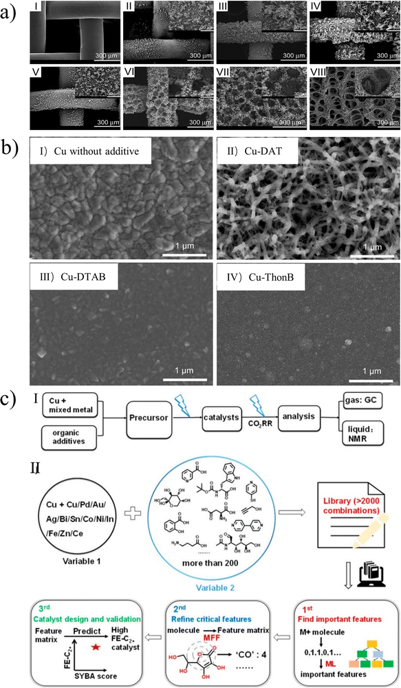 | ||
| Fig. 6 (a) SEM images of copper electrodes prepared by electrodeposition at different potentials. Reproduced with permission.36 Copyright 2013, Elsevier. (b) SEM images of Cu electrodeposited (I) without additive, (II) with DAT, (III) with dodecyltrimethylammonium bromide (DTAB), and (IV) with thonzonium bromide (ThonB). Reproduced with permission.37 Copyright 2017, American Chemical Society. (c) (I) Preparation of Cu electrocatalysts via electrochemical deposition followed by evaluation of catalytic performance. (II) Schematic illustration of machine-learning-guided optimization of additives for copper catalyst preparation. Reproduced with permission.43 Copyright 2021, American Chemical Society. | ||
In addition, the effect of electrolyte concentration on the deposition morphology is studied in Branco's work.36 They obtained the honeycomb-like structure by changing the concentration of H2SO4 to promote the attachment of hydrogen bubbles. With the increase of CuSO4 concentration, the reduction of copper ions is stronger than that of the HER, and the pore size and wall thickness are enhanced. This structure is beneficial to the rapid transport of gas and liquid, and the higher specific surface area is beneficial to CDRRs. The results show that the methane current efficiency decreases and the ethylene selectivity is enhanced for the catalyst deposited at higher overpotentials.
In the electrodeposition process, additives are often added into the bath to control the fine transform of the morphology and surface structure of the catalyst. As shown in Fig. 6b, Gewirth et al. used 3,5-diamino-1,2,4-triazole (DAT) as an electrodeposition inhibitor to control the morphology of copper alloys, and obtained catalyst with a high specific surface area and porous structure.37 Some studies have found that additives can form complexes with metals to participate in the catalytic process while regulating the morphology of the catalysts. Xu et al. investigated the electrodeposition of copper phosphate complex by modifying the electrode with phosphate ligands.41 Phosphate anions form complexes with free Cu(II), which compete with the electrodeposition process, resulting in dendrites replacing aggregates. Moreover, Lin et al. used EDTA as an additive for both structural induction and ligand effect, and then creatively generated ligand-modified porous hollow copper through the electrodeposition process.42 The charge and space interaction between EDTA and OCCO adsorbent is helpful to stabilize the lower activation barrier and facilitate the formation of ethylene.
The choice of substrate also has a great influence on the performance of the catalyst; the most commonly used substrates are carbon paper-based gas diffusion layer40,55 and metal.24,52–54 Different substrates can result in different growth orientations of catalysts. As shown in Fig. 3a, the dendrite morphology of Cu is formed on both Ag and Pt substrates, but its properties are quite different. When the substrate was Pt, the HER was severe due to the exposure of the substrate. On the contrary, the exposure of Ag increased the production of CO, and the special acicular structure enhanced the selectivity of the C2–C3 products.
It is undeniable that additives have a non-negligible effect on the morphology and performance of catalysts. However, a reserve system that integrates theoretical guidance may allow us to make better use of them. Recently, Wang et al. provided a new path for additive selection and optimization by combining experiment and theory with efficient data analysis through machine guidance (Fig. 6c).43 They indicate that the Sn salt can be used as an important additive for the production of CO and HCOOH, while aliphatic alcohols can promote the formation of Cu2O cubes in the electrodeposition process, which tends to produce C2+ products.
There are many influencing factors of electrodeposition, due to its huge technical parameter space. In addition to the above-mentioned factors, deposition time,44 pH45 and other factors also have a non-negligible influence. The huge parameter space means infinite possibilities, but also one of the biggest challenges.
4.2 Characterization methods
There are many sophisticated characterization instruments currently available for the detailed characterization of electrocatalysts. Here, we introduce some conventional methods for characterizing electrodeposited catalysts and their functions, so that we can better understand the morphology, internal structure and other properties of catalysts.SEM can be used to observe the microscopic morphology of substances, and at the same time, it can also be used to analyze the composition of micro-areas of substances. Fig. 7a shows the SEM images of mesoporous copper foam deposited on the Cu substrate at different deposition times.46 The deposition rate is limited by the mass transport of metal ions and the mobility of adsorbed atoms on the electrode surface.
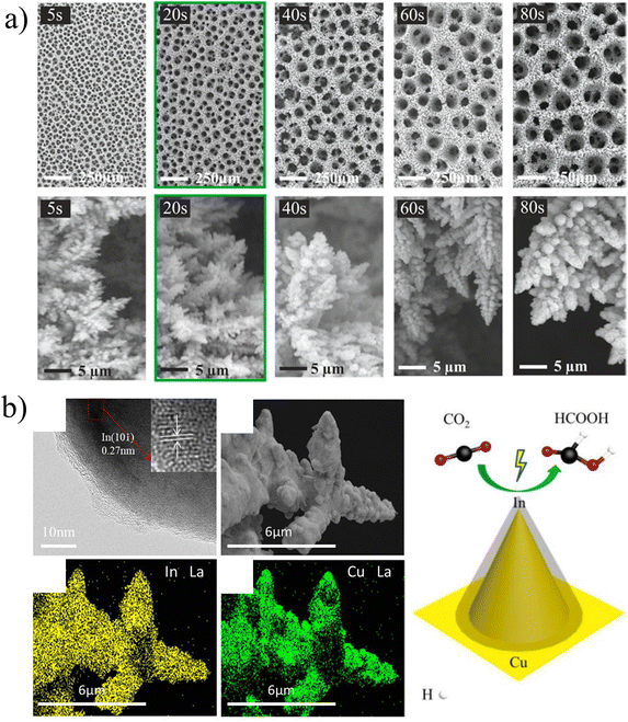 | ||
| Fig. 7 (a) SEM micrographs showing the changes of surface pore size and dendrite size with deposition time. Reproduced with permission.46 Copyright 2021, American Chemical Society. (b) HRTEM images of the Cu–In-30 catalyst, SEM image of the Cu–In-30 catalyst, and the corresponding EDX elemental maps. Reproduced with permission.47 Copyright 2021, American Chemical Society. | ||
A HR-TEM (high resolution transmission electron microscope) can be employed to observe the crystal plane, so as to calibrate the crystal plane orientation or the growth direction of the material. Fig. 7b shows the TEM image of the Cu–In catalyst.47 In the enlarged local region, the characteristic space of the lattice is observed, which is 0.27 nm and fits well with the indium(101) plane. The morphology and element distribution are closely related to the electrodeposition conditions, and the properties of the catalyst have a huge impact on the performance.
X-Ray diffraction (XRD) is one of the most basic structural characterization methods, mainly used for phase analysis. Fig. 8a-I shows the XRD patterns of the electrodeposited CuAg catalyst in different states, and the transformation of metal and oxide was analyzed, providing direct evidence of the activation of the catalyst under thermal annealing.59Fig. 8b shows the XRD result of AgCu-10 and AgCu-50 at different deposition times.48 The main phases of the catalyst are Cu2O and Ag. The peaks with different diffraction angles represent different crystal planes, and the intensity of crystallization peaks increases with the increase of the deposition time.
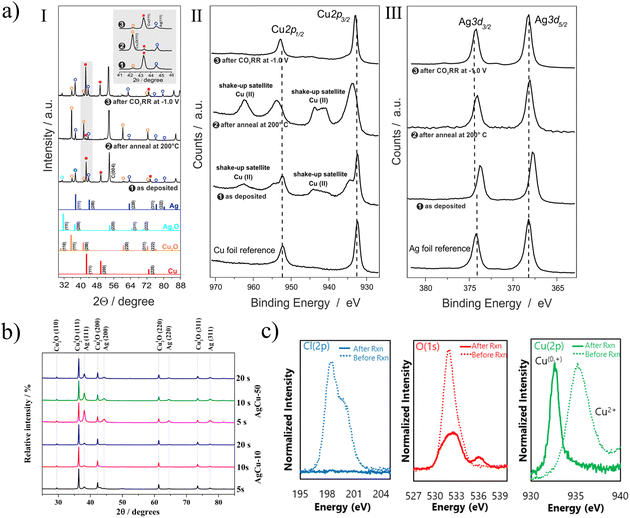 | ||
| Fig. 8 (a) (I) XRD patterns of the as deposited Ag15Cu85 foam, the annealed foam (12 h at 200 °C), and OD-Ag15Cu85 (after 1 h CO2RR at −1.0 V vs. RHE); (II and III) corresponding XPS of the bimetallic foam. Reproduced with permission.59 Copyright 2020, Elsevier. (b) XRD patterns of AgCu film electrodeposited. Reproduced with permission.48 Copyright 2019, American Chemical Society. (c) XPS spectra of electro-redeposited (ERD) copper before and after the reaction. Reproduced with permission.49 Copyright 2018, Macmillan Publishers Limited. | ||
Since XRD is only sensitive to reveal the bulk phase of the long-range translation order, the complementary X-ray photoelectron spectroscopy (XPS) analysis is more sensitive to the chemical state of the catalyst surface. Fig. 8a-II and III describe the Cu 2p and Ag 3d nuclear level emissions of bimetallic catalyst materials at different stages of preparation and use.59 XPS spectra of silver foil and copper foil samples are also provided as reference. Apparently, Cu(II) species already existed on the deposited foam. As shown in Fig. 8c, dicopper chloride trihydroxide is used as a precursor for carbon dioxide reduction.49 It can be seen that there is almost no Residual Cl ion after the reaction, and the strength of oxygen after the reaction is also significantly reduced, indicating that CuO has been reduced. However, it is difficult to distinguish Cu2O from Cu on XPS after reaction. Further analysis of X ray absorption spectrum (sXAS) can prove the existence of Cu+. The effective combination of various characterization methods can make us better obtain the properties and changes of catalyst, so as to further study its catalytic mechanism. It can better guide researchers to synthesize catalysts.
With the development of CDRRs, traditional characterization techniques are unable to meet the increasing needs. In situ testing technology has gradually entered the core area of scientific research. For example, operando hard X-ray absorption spectroscopy (hXAS) can be used to monitor the formation and transformation of catalysts in real time during the test, and even observe the exposure of crystal planes.50 To monitor the specific process of CDRRs, in situ surface-enhanced Raman spectroscopy (SERS) can be used to capture the appearance of important intermediates, such as the peaks of Cu–CO.75 With the progress and popularization of in situ characterization technology, it is believed that this will greatly promote the research of CDRRs.
5. Application of electrodeposition in CDRRs
The development of catalytic CO2 towards the production of high value-added fuels has a positive impact on the world's energy and environment. Electrodeposition has been widely studied and promoted in CDRRs owing to its advantages of cost effectiveness and environmental friendliness. The latest progress in the synthesis of catalytic CO2 reduction catalysts by electrodeposition is summarized below. Table 1 presents data for some CDRR catalysts prepared by electrodeposition.| Electrocatalyst | Preparation method | Electrolyte | Potential (vs. RHE) | Product | FE (%) | J(mA cm−2) | Stability | Ref. |
|---|---|---|---|---|---|---|---|---|
| Cu (100)-rich copper | In situ electrodeposition | 1 M KOH | −0.38 V to −0.74 V | C2+ | 90 | 520 | 65 h | 50 |
| Porous 3D Cu skeletons | Electrodeposition | 0.5 M KHCO3 | −1.1 V | C2 (C2H4, C2H6) | 29.1 | — | — | 51 |
| Nanoscale Ag grains (40–100 nm) | Galvanostatic electrodeposition | 0.5 M KHCO3 | — | CO | Over 90 | 14 | — | 52 |
| Ag foam | Galvanostatic electrodeposition | 0.5 M KHCO3 | −1.5 V | CH4 | 51 | — | 5 h | 53 |
| 0.5 M KHCO3 | −0.8 V | CO | 90 | — | 70 h | |||
| Sn-DT GDE | Potentiostatic electrodeposition | 1 M KHCO3 | −0.76 V | HCOOH + CO | 91 | 14 | 72 h | 55 |
| Zn dendrite | Galvanostatic electrodeposition | 0.5 M KHCO3 | −0.9 V | CO | 80 | 4 | — | 56 |
| Bi-CMEC | Potentiostatic electrodeposition | Ionic liquid | — | CO | ≈95 | 5.51 | — | 16 |
| CuxZn | Galvanostatic electrodeposition | 0.1 M KHCO3 | −1.05 V | C2H6O | 29.1 | 8.2 | 5 h | 58 |
| Cu@Sn | Galvanostatic electrodeposition | 0.5 M KHCO3 | −0.93 V | HCOOH | ≈100 | 16.52 | 15 h | 60 |
| Cu–Sn | Electrodeposition–calcination | 0.1 M KHCO3 | −1.0 V | HCOOH | 82 | 18.9 | 42 h | 62 |
| SnCu | Potentiostatic electrodeposition | 0.5 M KHCO3 | −1.2 V | HCOOH | 78 | 88 | 250 min | 63 |
| In55Cu45 | Electrodeposition | 0.5 M KHCO3 | −1.0 V | HCOOH | 96.8 | 8.9 | 30 h | 65 |
| Cu–Pd | Pulse electrodeposition | 0.1 M KHCO3 | −1.2 V | CH4 | 32 | — | — | 30 |
| Cu–Pd | Galvanostatic electrodeposition | 0.1 M KCl | −1.2 V | C2H4 | 45.2 | 17.4 | — | 67 |
| CuBi | Co-electrodeposition | 0.5 M KHCO3 | −1.07 V | HCOOH | 98.3 | 56.6 | — | 68 |
| GB-Cu | Potentiostatic electrodeposition | — | −1.0 V | C2 | 70 | 52 | 180 min | 72 |
| Cu | Electrodeposition | 0.1 M KHCO3 | −1.1 V | C2H4 | 27.8 | 11.8 | 12 h | 73 |
| Cu foam | Galvanostatic electrodeposition | 0.1 M NaHCO3 | −0.98 V | C2H4 | 26 | 60 | — | 74 |
| Cu–P1 | Co-electrodeposition | 10 M KOH | −0.47 V | C2H4 | 87 | — | — | 75 |
5.1 Electrodeposited elemental materials
Transition metals are mostly reported as active materials for CDRRs, but low activity and small specific surface area are also problems that need to be solved urgently in this field. Electrodeposition, as one of the most active fields of current material preparation, can yield nanomaterials of various sizes and morphologies. Moreover, the method is not only relatively simple, but also the obtained materials often exhibit high catalytic activity. Cu,50,51 Ag,52–54,57 Sn,55 Zn,56 Bi,16etc. have been effectively used in electrodeposition catalysts. For example, Sargent et al. synthesized copper with abundant (100) facets by in situ electrodeposition, as shown in Fig. 9a.50 During the electrodeposition of Cu, the ratio of Cu(100) facets was increased by 70%, and C2+ products with an FE of 90% were achieved at 520 mA m−2. The adsorption of CDRR intermediates reduced the surface energy of high-energy copper surfaces, such as Cu(100) facets. This capping effect was similar to colloidal crystal synthesis, regulating the growth of copper and increasing the proportion of (100) planes. Ag has been shown to be effective in converting CO2 to CO.54 Broekmann et al. obtained a foamed mesoporous silver catalyst by controlling silver growth with citrate additives.53 The CO efficiency does not fall below 90% in the range of −0.3 VRHE to −1.2 VRHE (Fig. 9b). Most interesting is the ability of this foamed Ag catalyst to generate hydrocarbons, reaching 51% and 8.6% for FECH4 and FEC2H4 at −1.5 VRHE, respectively. This is attributed to the significant increase in the binding energy of the novel silver foam to *CO.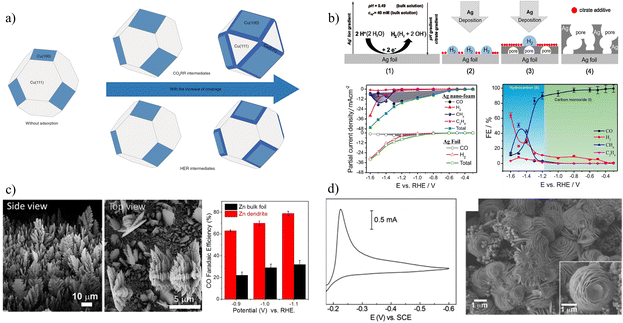 | ||
| Fig. 9 (a) Schematic diagram of crystal plane distribution when covered by different intermediates. Reproduced with permission.50 Copyright 2020, Springer Nature. (b) Preparation and catalytic performance of silver nanofoam. Reproduced with permission.53 Copyright 2018, American Chemical Society. (c) SEM image and performance distribution diagrams of zinc catalysts. Reproduced with permission.56 Copyright 2015, American Chemical Society. (d) Cyclic voltammogram (CV) in 1.0 M HCl (aq.) and 0.5 M KBr (aq.) containing 20 mM Bi3+ and SEM image of a Bi-modified glassy carbon electrode (GCE). Reproduced with permission.16 Copyright 2013, American Chemical Society. | ||
Despite the high activity of noble metals, low-cost metals have gained more attention to implement applications on a large scale driven by cost-effectiveness. For example, Jiao et al. reported a nanostructured Zn dendrite electrocatalyst by the electrodeposition method (Fig. 9c), which not only reduces the formation of surface oxide layer, but also creates a highly active catalyst with dendritic.56 At an electrodeposition rate of 1.0 A cm−2, Zn dendrites with highly branched nanostructures can be formed. Under environmental conditions, dendrite Zn catalyst has significant electrochemical CO2 reduction performance, and its activity is about 3 times higher than that of Zn foil, which is attributed to its higher active surface area. Rosenthal and his team electrodeposited cheap Bi material onto glassy carbon electrodes (Fig. 9d).16 The catalyst can be used with ionic liquids to effectively convert CO2 to CO at an overpotential of less than 0.2 V, and the FE is about 95%. The interface between Bi0 and Bi3+ sites may play a role in stabilizing CO2˙− intermediates.
Consequently, as a simple and effective method for preparing catalysts, electrodeposition has been successfully applied to the CDRRs of metals and has become one of the preferred methods for the preparation of catalysts by researchers. As the method matures, the combination with other technologies gradually expands its application.5 It is foreseeable that electrodeposition will gradually develop towards refinement and industrialization.
5.2 Electrodeposition of binary alloys
Compared with single metal, bimetallic component catalysts often exhibit synergistic effects, geometric effects or coupling effects, and are expected to greatly reduce the cost, which is one of the important directions in the field of electrocatalysis.At present, most research studies focus on the combination of Cu with another metal to improve the CDRR performance, such as CuZn,58 CuAg,17,59 CuSn,28,60–63 CuPb,64 CuIn,47,65,66 CuPd,67 CuBi,68etc. In Fig. 10a, Yeo et al. proposed a strategy to compensate for the insufficient CO solubility by introducing CuxZn alloys to catalyze the in situ generation of CO during the CO2RR process.58 CO is weakly adsorbed on the Zn site and easily diffuses into the Cu matrix, increasing the concentration of *CO intermediate, and the intermediate bonds with *CH2 to form *COCH2 to further generate ethanol. At −1.05 VRHE, Cu4Zn can reach the FE of ethanol (29.1%) and the current density (−8.2 mA m−2). Moreover, Gewirth fabricated a catalyst with a high specific surface area by electrodepositing CuAg alloy films in an additive bath.17 The faradaic efficiencies of C2H4 and C2H5OH are close to 60 and 25% (Fig. 10b), respectively. Ag promotes the formation of Cu2O, which is beneficial to improve the production efficiency of CO and C2H4. Moreover, Strasser et al. tuned the selectivity and efficiency of electrochemical CO2 reduction by controlling the inhibition of the hydrogen evolution reaction channel.64 They demonstrate an unusually high selectivity for formate (HCOO−) over a wide range of overpotentials when a small amount of sub-monolayer Pb atoms is deposited on the Cu surface. In short, although there have been many studies on binary alloys of Cu with enhanced selectivity, the research on commercialization is relatively lacking and relevant research is urgently needed.
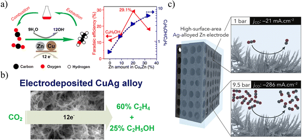 | ||
| Fig. 10 (a) Schematic diagram of ethanol production from CuZn alloy. Reproduced with permission.58 Copyright 2016, American Chemical Society. (b) Schematic diagram of the production of C2 products from CuAg alloys. Reproduced with permission.17 Copyright 2018, American Chemical Society. (c) Schematic diagram of efficient CO production from AgZn alloy. Reproduced with permission.27 Copyright 2019, Elsevier Inc. | ||
Compared with the binary alloys of copper, combination studies of other metals are rare. One of the reasons is that it lacks the ability to produce hydrocarbons and the main research is on CO27,70 and HCOOH.69 The extremely high selectivity may give it a huge potential to industrialize earlier. Fontecave et al. optimized the Ag content, porosity, thickness and specific surface area by adjusting the electrodeposition parameters to prepare a AgZn dendritic electrode.27 The selectivity of CO2 to CO conversion was higher than 91%, and remained above 90% on an average within 40 h. As shown in Fig. 10c, after increasing the pressure of CO to 9.5 par, the current density of CO2 to CO can reach 286 mA cm−2. For cost consideration, Li et al. used electrodeposition technology to deposit cheap Bi and Sn on the copper mesh to obtain similar pine needle-shaped dendritic structured BiSn metal electrodes.69 The Bi5Sn60 electrode has good catalytic activity for CO2 reduction at −1.0 VRHE, the FE of formic acid is as high as 94.8%, the partial current density is 34 mA m−2, and the yield is 636.3 μmol cm−2 h−1. At a constant potential of −1.0 V, the alloy was stable for 20 h while maintaining a high FE. The good performance is attributed to the large active surface area and abundant active sites of the catalyst, as well as the fast charge transfer brought by the optimized structure.
The combination of binary alloys has greatly improved the performance and stability of catalysts. However, there have been many research studies on binary alloys, but most of them are attributed to the synergistic effect of alloys. The effect of the distance between different metal active sites in bimetallic component catalysts on the catalytic activity is not yet clear,71 and deep research at the atomic level may provide further understanding of binary alloys, and also help us obtain better theoretical guidance to prepare alloys.
5.3 Combination of additives and metals
(1) Additives are mostly used as inhibitors and corrosion inhibitors to control the morphology and improve the performance and selectivity of catalysts. Gong et al. introduced a method for controlled grain growth of copper electrodeposition with polyvinylpyrrolidone (PVP) as an additive (Fig. 11a).72 In terms of kinetics, PVP is an inert polymer that can be reversibly adsorbed on the copper surface to kinetically increase the nucleation rate and decrease the crystal size. Compared with Cu electrocatalysts, grain boundary-rich Cu exhibits higher selectivity (FE = 70%) for C2 products in the range of −1.0 to −1.3 VRHE. Cuenya et al. prepared prismatic Cu electrocatalysts using crystal-modifying additives.73 The change of the additive concentration (Janus Green B) can make the prism width more uniform and narrower, the surface rougher, and the defect site concentration higher. The large number of defects on the surface of the catalyst plays an important role in improving the production of C2H4.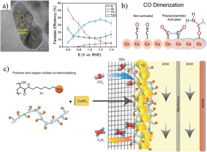 | ||
| Fig. 11 (a) HRTEM image of grain boundary-rich copper catalyst (GB-Cu) and its catalytic performance. Reproduced with permission.72 Copyright 2020, American Chemical Society. (b) Schematic diagram of poly-amide modified copper foam electrodes. Reproduced with permission.74 Copyright 2018, American Chemical Society. (c) Schematic illustration of poly-N-(6-aminohexyl)acrylamide (P1) and Cu co-electroplating on the gas diffusion layer (GDL). Reproduced with permission.75 Copyright 2021, Springer Nature. | ||
(2) Some additives can also be adsorbed on metals through bonding during the deposition process, or form complexes with metals to participate in catalysis. For example, Andreoli et al. obtained a polyacrylamide-modified Cu electrode by electrodepositing copper in an additive-added bath (Fig. 11b).74 DFT calculations indicated that polyacrylamide was adsorbed on copper through oxygen on the carbonyl group. The additive also promotes the adsorption of CO molecules, thereby enhancing the generation of C2H4. Appropriate additives can promote the progress of the CDRR reaction.
(3) Adding additives that alter the stability of the intermediates on the electrode surface can increase the CDRR activity. Unfortunately, small molecules decorated on the catalyst surface are usually desorbed and removed in the flow cell. Therefore, the co-deposition of polymer and copper on the electrode surface can maintain the required entrainment function. To understand the effect of polymers on the electrocatalytic activity, Gewirth et al. co-deposited poly-n-(6-aminohexyl)acrylamide and copper to make Cu-polymer electrodes (Fig. 11c).75 In 1 M KOH, the FE of ethylene reaches 72% at −0.97 VRHE, and the partial current density of ethylene can reach −312 mA cm−2. Amino groups on the electrode surface can change the reactivity and surface pH to capture CO2, resulting in a higher local concentration of CO2 on the surface.
The use of additives affects the electrodeposition process and even the catalyst performance to a great extent, but its limitations are rarely mentioned in the literature. First, the excessive use of catalysts deviates from green electrochemistry. Second, the position of the additive attached to the catalyst is random and easy to fall off, resulting in its general stability. Therefore, a green, easy-to-recycle, and stable additive may provide a reference for the selection of additives.
5.4 Electrodeposition synthesis of high-entropy alloys
One of the earliest papers defined HEAs as “an element consisting of five or more principal elements in equal molar ratios”.76 The requirement for equal molarity is limited, and the definition is expanded to include “concentrations of each element between 5% and 35%”. The HEA field introduces new ideas and deliberately explores the vast field of hyperdimensional complex component space. For example, Nellaiappan et al. used nano-AuAgPtPdCu to convert CO2 into hydrocarbons.77 At a low applied potential (−0.3 VRHE), the FE for gaseous products is approximately 100%. Electrocatalytic activity is mainly attributed to the presence of redox-active copper metal (Cu2+/Cu0), while other metals provide only synergistic effects. This is one of the few examples of high-entropy alloys used in CDRRs, although it is not synthesized by electrodeposition.The concept of entropy was also introduced into binary alloys, Takeguchi et al. proposed an entropy-based adsorption theory that alloys with random distributions can weaken the adsorption of *CO.78 Therefore, high-entropy state CuSn alloys (Cu6Sn5) may not be suitable for *CO adsorption, while low-entropy state CuSn alloys may provide enhanced *CO adsorption capacity and subsequent enhanced C2 product selectivity. Based on this, Zheng et al. developed a bimetallic low-entropy Cu3Sn catalyst with high efficiency for CO2 reduction to ethanol, with an FE of 64%.79 At an industrial current density of −900 mA cm−2, the Cu3Sn catalyst exhibits excellent stability over 48 h.
As a brand-new alloy system, high-entropy alloys have great advantages in material stability, strength, and electrochemical properties. At present, the preparation of high-entropy alloys by electrodeposition for CDRRs is extremely rare. Reasonable design and preparation of ideal high-entropy alloys have broad application prospects in CDRRs.
5.5 Exploration of industrialization
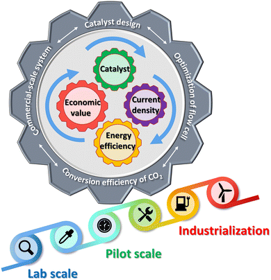
With the gradual maturity of traditional electrodeposition technology, its application is becoming more and more extensive. However, most research studies have focused on developing novel catalysts with excellent performance and good stability. Perhaps our focus should turn to the path of industrialization, and Fig. 12 expresses some of our prospects for industrialization. Operation in the laboratory with H-cells is far from being scaled up for commercialization. For large-scale conversion of CO2, the main impediment is the solubility of CO2 in water (∼0.03 mol kg−1 at ∼300 K and 1 atm).80 Currently, electrolyzers with flow have been used in CDRRs, and flow reaction cells can transport more reagents, thereby reducing the mass transport problems inherent in H cells. Second, CO2 can be delivered to the cathode in the gas phase, providing a new way to generate higher current densities. Here we mainly introduce some studies and suggestions that are close to industrialization.As we know, the market for methane, ethane, methanol, formic acid and ethylene is huge and in short supply (Fig. 13a). The advancement of carbon neutrality is also imperative. However, we lack a system of business models to integrate which products are our identified goals, and second, the huge cost of electrocatalytic CO2 reduction has also become a hindrance to commercialization. Electrolyzers with high power, high selectivity and stability are what we must explore. For example, Gewirth et al. electrodeposited CuSn-DAT catalyst on a carbon paper-based gas diffusion layer (GDL) with 3,5-diamino-1,2,4-triazole (DAT) as the buffer.40 The CuSn-DAT electrode exhibits the highest FE for CO (∼90% at −0.4 VRHE) and C2H4 (∼60% at −0.8 VRHE) production and high current density (−225 mA cm−2 at −0.8 V) in a flow cell. As shown in Fig. 13b, the flow cell consists of anode, cathode and electrolyte flow channels. When the reaction takes place, CO2(g) is supplied to the cathode side, where it diffuses to the electrocatalyst to be reduced; OER occurs at the anode, and is released into the air. As shown in Fig. 13c, Sargent et al. deposited copper using carbon-based GDL and polymer-based GDL as substrates, respectively.81 In strongly basic media, the abrupt interface formed on the catalyst enables ethylene incorporation to progress. The bias current density of ethylene at −0.67 VRHE reached 473 mA cm−2. GDL is a porous material, and catalysts are immobilized on these layered materials to make gas diffusion electrodes (GDEs). The current density is highly important for industrialization (Fig. 13a).82 Laboratory-scale flow cells provide an opportunity for further efficient CDRRs and are gaining increasing attention. This is a critical step towards carbon neutrality and one of CDRR's paths towards industrialization. It is believed that with the continuous in-depth research on flow cells, industrial-scale CDRRs will be realized in the near future.
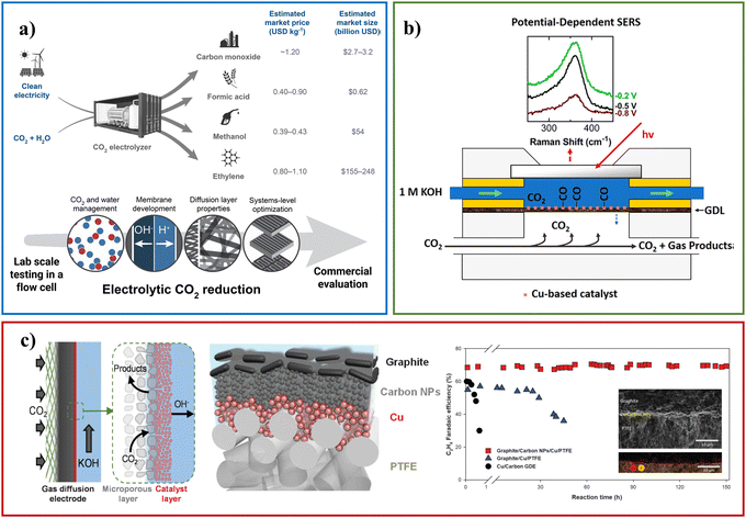 | ||
| Fig. 13 (a) An overview of the market for CDRR products and the application of flow cell. Reproduced with permission.82 Copyright 2018, American Chemical Society. (b) Schematic diagram of the flow tank structure. Reproduced with permission.40 Copyright 2019, American Chemical Society. (c) Schematic diagrams of flow cell cathode and the catalytic performance. Reproduced with permission.81 Copyright 2018, American Association for the Advancement of Science. | ||
In addition to the attempts on electrolyzers, the researchers also considered various factors conducive to industrialization, such as the production of CO under high pressure,27 the large-area electrodes,83 the recovery of electrodeposition waste liquid,84 and the use of low-sink metals to efficiently prepare CO.85,86 For example, large-area gas diffusion electrodes are of great significance. Kim et al. fabricated large-area (25.5 and 136 cm2) Ag gas diffusion electrodes by electrodeposition. And it was successfully combined with MEA-type CO2 electrolyzer.83 The preparation of large-area electrodes has more stringent technical requirements, and it is necessary to accurately control and compare factors such as electrode system, electrode arrangement, deposition current and deposition time. In this way, a catalyst with uniform deposition and good morphology can be obtained to ensure that its catalytic activity reaches a high level. The 136 cm2 Ag GDE fabricated under optimal conditions has an effective geometric area of 107.44 cm2 in an MEA-type CO2 electrolyzer, giving potential-dependent CO conversion efficiencies of 41.99–57.75% at Vcell = 2.2–2.6 V. Although the performance of the catalyst has not reached the high level of laboratory research, and it also faces many technical problems, it is undoubtedly an effective attempt for commercialization. The next development direction should be focused on solving key technical challenges, such as the optimization and update of electrolyzers.87,88 Excellent technologies from various fields need to be reasonably combined to overcome difficulties in the industrialization of CDRRs.
6. Summary and outlook
In this review, we discuss in detail the progress of electrodeposition technology as a promising alternative for preparing highly active and stable CDRR catalysts. We introduce several general electrodeposition methods such as galvanostatic deposition, potentiostatic deposition, and pulsed deposition. The catalysts synthesized by different electrodeposition methods also have different characteristics, morphologies, and the corresponding performance differences.Undoubtedly, the preparation of catalysts by electrodeposition has many advantages. Simultaneously, different experimental parameters can create different catalysts in electrodeposition technology. Experimental parameters such as current density, electrolyte, pH, and additives have their own influence and play a crucial role in obtaining an ideal catalyst, which is also one of the biggest challenges posed by electrodeposition technology.
We also outline the application of electrodeposition in CDRRs. The exploration of additives, units, and binary metals has gradually deepened, while multi-element and even high-entropy still need a long way to be explored. According to the current research progress and some gaps in the field, we give the following suggestions:
(1) Given the low cost and easy scalability of electrodeposition, it is attractive for the preparation of electrochemical CO2 reduction catalysts. In order to achieve industrialization, it is necessary to overcome the shortcomings of traditional electrodeposition lacking metering control, establish a complete database, accurately adjust electrochemical methods and experimental parameters, and expand the relatively mature technology in the laboratory to large-scale experiments.
(2) Surface modification is an important strategy to modulate the selectivity, and it is also a complex engineering process. Modifications of amines, halogens, and polymers have been reported one after another. By combining theoretical calculation simulations and experiments, the number of effective modified molecules can be expanded faster and more accurately, providing a feasible and effective strategy for improving the C2+ product efficiency of CDRRs.
(3) The limitations of traditional electrodeposition technology need to be overcome and a new catalyst system should be developed, for example, the preparation of high-entropy alloys mentioned in this article, the preparation of single-atom catalysts, etc. Wang et al. introduced the synthesis and application of high-entropy alloys in detail.89 Zeng et al. successfully obtained a variety of single-atom HER catalysts using electrodeposition through different metal precursors and supports.90 Sun et al. summarized the applications and preparations of single-atom catalysts in CDRRs, and introduced the relationship between their structures and properties.91 In addition, 2D nanosheets have abundant low-coordination atoms and a large specific surface area, which is one of the candidates for electrochemical catalysis.92 It is believed that combining electrodeposition technology with new materials holds promise for CDRRs.
(4) There are many factors that affect the selectivity and efficiency of electrodeposition catalysts, including material composition, crystal structure, microscopic morphology, electronic state, etc. Making full use of advanced characterization and measurement techniques (in situ optics, X-ray) and theoretical calculations to detect the actual deposition operation and even the process of CDRRs is of great help in further understanding the relationship between materials and reaction mechanisms. In particular, in the face of the complex reaction process, the catalyst itself undergoes a large structural evolution, and we need to reveal the key influencing factors. Advanced technology will undoubtedly help our research in depth.
(5) In the face of increasingly high industry requirements, the reference and cooperation between different technologies may bring electrodeposition technology to a new level, for example, in terms of technology, plasma treatment of the substrate before deposition to further increase the surface roughness of the substrate or to obtain a substrate with doped properties. The electrodeposited material is further calcined to obtain a more stable material. In terms of theory, in the age of information data, machine learning has become an inevitable path. Combining the guidance of machine learning with the effective screening and preparation of catalysts will be an effective way to develop high-performance catalysts.
(6) In the carbon neutrality, there is no doubt that CDRRs are one of the promising areas to settle energy and environmental problems. With the in-depth study, current density, energy efficiency, CO2 utilization and even economic benefits93 have gradually become the focus for scientific researchers. Electrodeposition technology is one of the most cost-effective synthesis methods, so it has become an excellent choice for catalysts. In order to adapt to new demands, electrodeposition technology needs to be integrated with GDEs and applied in the state-of-the-art device systems. Only this way can make it one of the best choices for future industrialization.
Conflicts of interest
The authors declare no conflict of interest.Acknowledgements
This work was financially supported by the Certificate of postdoctoral research grant in Henan province and the Natural Science Foundation of Henan province (Grant No. 212300410281).References
- P. Friedlingstein, R. M. Andrew, J. Rogelj, G. P. Peters, J. G. Canadell, R. Knutti, G. Luderer, M. R. Raupach, M. Schaeffer, D. P. van Vuuren and C. Le Quéré, Persistent growth of CO2 emissions and implications for reaching climate targets, Nat. Geosci., 2014, 7(10), 709–715 CrossRef CAS.
- S. C. Roy, O. K. Varghese, M. Paulose and C. A. Grimes, Toward solar fuels: photocatalytic conversion of carbon dioxide to hydrocarbons, ACS Nano, 2010, 4(3), 1259–1278 CrossRef CAS PubMed.
- D. Gao, R. M. Arán-Ais, H. S. Jeon and B. Roldan Cuenya, Rational catalyst and electrolyte design for CO2 electroreduction towards multicarbon products, Nat. Catal., 2019, 2(3), 198–210 CrossRef CAS.
- Z. Xie, X. Zhang, Z. Zhang and Z. Zhou, Metal-CO2 batteries on the road: CO2 from contamination gas to energy source, Adv. Mater., 2017, 29(15), 1605891 CrossRef.
- S. Liu, H. Tao, L. Zeng, Q. Liu, Z. Xu, Q. Liu and J. L. Luo, Shape-dependent electrocatalytic reduction of CO2 to CO on triangular silver nanoplates, J. Am. Chem. Soc., 2017, 139(6), 2160–2163 CrossRef CAS PubMed.
- W. Luo, J. Zhang, M. Li and A. Züttel, Boosting CO production in electrocatalytic CO2 reduction on highly porous Zn catalysts, ACS Catal., 2019, 9(5), 3783–3791 CrossRef CAS.
- S. Zhang, X.-T. Gao, P.-F. Hou, T.-R. Zhang and P. Kang, Nitrogen-doped Zn–Ni oxide for electrochemical reduction of carbon dioxide in sea water, Rare Met., 2021, 40(11), 3117–3124 CrossRef CAS.
- X. Wang, F. Li, W.-J. Yin, Y. Si, M. Miao, X. Wang and Y. Fu, Atomically dispersed Sn modified with trace sulfur species derived from organosulfide complex for electroreduction of CO2, Appl. Catal., B, 2022, 304, 120936, DOI:10.1016/j.apcatb.2021.120936.
- X. Wang, W.-J. Yin, Y. Si, X. Wang, X. Guo, W. Guo and Y. Fu, Conversion of CO2 to chemical feedstocks over bismuth nanosheets in situ grown on nitrogen-doped carbon, J. Mater. Chem. A, 2020, 8(38), 19938–19945 RSC.
- J. D. Yi, R. Xie, Z. L. Xie, G. L. Chai, T. F. Liu, R. P. Chen, Y. B. Huang and R. Cao, Highly selective CO2 electroreduction to CH4 by in situ generated Cu2O single-type sites on a conductive MOF: stabilizing key intermediates with hydrogen bonding, Angew. Chem., Int. Ed., 2020, 59(52), 23641–23648 CrossRef CAS PubMed.
- J.-J. Li and Z.-C. Zhang, K+-enhanced electrocatalytic CO2 reduction to multicarbon products in strong acid, Rare Met., 2021, 41(3), 723–725 CrossRef.
- X. Wang, Z. Wang, F. P. García de Arquer, C.-T. Dinh, A. Ozden, Y. C. Li, D.-H. Nam, J. Li, Y.-S. Liu, J. Wicks, Z. Chen, M. Chi, B. Chen, Y. Wang, J. Tam, J. Y. Howe, A. Proppe, P. Todorović, F. Li, T.-T. Zhuang, C. M. Gabardo, A. R. Kirmani, C. McCallum, S.-F. Hung, Y. Lum, M. Luo, Y. Min, A. Xu, C. P. O’Brien, B. Stephen, B. Sun, A. H. Ip, L. J. Richter, S. O. Kelley, D. Sinton and E. H. Sargent, Efficient electrically powered CO2-to-ethanol via suppression of deoxygenation, Nat. Energy, 2020, 5(6), 478–486 CrossRef CAS.
- S. Lee, D. Kim and J. Lee, Electrocatalytic production of C3–C4 compounds by conversion of CO2 on a chloride-induced Bi-phasic Cu2O-Cu catalyst, Angew. Chem., Int. Ed., 2015, 54(49), 14701–14705 CrossRef CAS PubMed.
- Y. Pan, R. Lin, Y. Chen, S. Liu, W. Zhu, X. Cao, W. Chen, K. Wu, W. C. Cheong, Y. Wang, L. Zheng, J. Luo, Y. Lin, Y. Liu, C. Liu, J. Li, Q. Lu, X. Chen, D. Wang, Q. Peng, C. Chen and Y. Li, Design of single-atom Co-N5 catalytic site: a robust electrocatalyst for CO2 reduction with nearly 100% CO selectivity and remarkable stability, J. Am. Chem. Soc., 2018, 140(12), 4218–4221 CrossRef CAS.
- J. Wang, H. Yang, Q. Liu, Q. Liu, X. Li, X. Lv, T. Cheng and H. B. Wu, Fastening Br–ions at copper–molecule interface enables highly efficient electroreduction of CO2 to ethanol, ACS Energy Lett., 2021, 6(2), 437–444 CrossRef CAS.
- J. L. DiMeglio and J. Rosenthal, Selective conversion of CO2 to CO with high efficiency using an inexpensive bismuth-based electrocatalyst, J. Am. Chem. Soc., 2013, 135(24), 8798–8801 CrossRef CAS PubMed.
- T. T. H. Hoang, S. Verma, S. Ma, T. T. Fister, J. Timoshenko, A. I. Frenkel, P. J. A. Kenis and A. A. Gewirth, Nanoporous copper-silver alloys by additive-controlled electrodeposition for the selective elctroreduction of CO2 to ethylene and ethanol, J. Am. Chem. Soc., 2018, 140(17), 5791–5797 CrossRef CAS.
- R. M. Aran-Ais, R. Rizo, P. Grosse, G. Algara-Siller, K. Dembele, M. Plodinec, T. Lunkenbein, S. W. Chee and B. R. Cuenya, Imaging electrochemically synthesized Cu2O cubes and their morphological evolution under conditions relevant to CO2 electroreduction, Nat. Commun., 2020, 11(1), 3489 CrossRef CAS PubMed.
- R. Kas, R. Kortlever, A. Milbrat, M. T. Koper, G. Mul and J. Baltrusaitis, Electrochemical CO2 reduction on Cu2O-derived copper nanoparticles: controlling the catalytic selectivity of hydrocarbons, Phys. Chem. Chem. Phys., 2014, 16(24), 12194–12201 RSC.
- M. W. Glasscott, A. D. Pendergast, S. Goines, A. R. Bishop, A. T. Hoang, C. Renault and J. E. Dick, Electrosynthesis of high-entropy metallic glass nanoparticles for designer, multi-functional electrocatalysis, Nat. Commun., 2019, 10(1), 2650 CrossRef PubMed.
- R. D. Caton, Reference electrodes, J. Chem. Educ., 1973, 50(12), A571 CrossRef CAS.
- Y. Tian, D. Li, J. Wu, J. Liu, C. Li, G. Liu, D. Chen and Y. Feng, Electroreduction of CO2 to formate with excellent selectivity and stability on nano-dendrite Bi film electrode, J. CO2 Util, 2021, 43, 101360 CrossRef CAS.
- C. Zhao and J. Wang, Electrochemical reduction of CO2 to formate in aqueous solution using electro-deposited Sn catalysts, Chem. Eng. J., 2016, 293, 161–170 CrossRef CAS.
- F. Scholten, I. Sinev, M. Bernal and B. Roldan Cuenya, Plasma-modified dendritic Cu catalyst for CO2 Electroreduction, ACS Catal., 2019, 9(6), 5496–5502 CrossRef CAS.
- W. Zhu, K. Zhao, S. Liu, M. Liu, F. Peng, P. An, B. Qin, H. Zhou, H. Li and Z. He, Low-overpotential selective reduction of CO2 to ethanol on electrodeposited CuxAuy nanowire arrays, J. Energy Chem., 2019, 37, 176–182 CrossRef.
- H. Jiang, L. Wang, Y. Li, B. Gao, Y. Guo, C. Yan, M. Zhuo, H. Wang and S. Zhao, High-selectivity electrochemical CO2 reduction to formate at low overpotential over Bi catalyst with hexagonal sheet structure, Appl. Surf. Sci., 2021, 541, 148577 CrossRef CAS.
- S. Lamaison, D. Wakerley, J. Blanchard, D. Montero, G. Rousse, D. Mercier, P. Marcus, D. Taverna, D. Giaume, V. Mougel and M. Fontecave, High-current-density CO2-to-CO electroreduction on Ag-alloyed Zn dendrites at elevated pressure, Joule, 2020, 4(2), 395–406 CrossRef CAS.
- K. Ye, A. Cao, J. Shao, G. Wang, R. Si, N. Ta, J. Xiao and G. Wang, Synergy effects on Sn–Cu alloy catalyst for efficient CO2 electroreduction to formate with high mass activity, Sci. Bull., 2020, 65(9), 711–719 CrossRef CAS.
- S. Kim, W. J. Dong, S. Gim, W. Sohn, J. Y. Park, C. J. Yoo, H. W. Jang and J.-L. Lee, Shape-controlled bismuth nanoflakes as highly selective catalysts for electrochemical carbon dioxide reduction to formate, Nano Energy, 2017, 39, 44–52 CrossRef CAS.
- J.-F. Xie, J.-J. Chen, Y.-X. Huang, X. Zhang, W.-K. Wang, G.-X. Huang and H.-Q. Yu, Selective electrochemical CO2 reduction on Cu–Pd heterostructure, Appl. Catal., B, 2020, 270, 118864 CrossRef CAS.
- X. Zhan, J. Lian, H. Li, X. Wang, J. Zhou, K. Trieu and X. Zhang, Preparation of highly (111) textured nanotwinned copper by medium-frequency pulsed electrodeposition in an additive-free electrolyte, Electrochim. Acta, 2021, 365, 137391 CrossRef CAS.
- M. W. Glasscott and J. E. Dick, Fine-tuning porosity and time-resolved observation of the nucleation and growth of single platinum nanoparticles, ACS Nano, 2019, 13(4), 4572–4581 CrossRef CAS.
- M. W. Glasscott, A. D. Pendergast and J. E. Dick, A universal platform for the electrodeposition of ligand-free metal nanoparticles from a water-in-oil emulsion system, ACS Appl. Nano Mater., 2018, 1(10), 5702–5711 CrossRef CAS.
- M. Yao, N. Wang, W. Hu and S. Komarneni, Novel hydrothermal electrodeposition to fabricate mesoporous film of Ni0.8Fe0.2 nanosheets for high performance oxygen evolution reaction, Appl. Catal., B, 2018, 233, 226–233 CrossRef CAS.
- C. T. J. Low, R. G. A. Wills and F. C. Walsh, Electrodeposition of composite coatings containing nanoparticles in a metal deposit, Surf. Coat. Technol., 2006, 201(1–2), 371–383 CrossRef CAS.
- M. R. Gonçalves, A. Gomes, J. Condeço, T. R. C. Fernandes, T. Pardal, C. A. C. Sequeira and J. B. Branco, Electrochemical conversion of CO2 to C2 hydrocarbons using different ex situ copper electrodeposits, Electrochim. Acta, 2013, 102, 388–392 CrossRef.
- T. T. H. Hoang, S. Ma, J. I. Gold, P. J. A. Kenis and A. A. Gewirth, Nanoporous copper films by additive-controlled electrodeposition: CO2 reduction catalysis, ACS Catal., 2017, 7(5), 3313–3321 CrossRef CAS.
- Z. Han, R. Kortlever, H. Y. Chen, J. C. Peters and T. Agapie, CO2 reduction selective for C ≥ 2 products on polycrystalline copper with N-substituted pyridinium additives, ACS Cent. Sci., 2017, 3(8), 853–859 CrossRef CAS PubMed.
- N. D. Nikolić, K. I. Popov, L. J. Pavlović and M. G. Pavlović, Morphologies of copper deposits obtained by the electrodeposition at high overpotentials, Surf. Coat. Technol., 2006, 201(3–4), 560–566 CrossRef.
- X. Chen, D. A. Henckel, U. O. Nwabara, Y. Li, A. I. Frenkel, T. T. Fister, P. J. A. Kenis and A. A. Gewirth, Controlling speciation during CO2 Reduction on Cu-alloy electrodes, ACS Catal., 2019, 10(1), 672–682 CrossRef.
- J. Zhao, L. Sun, S. Canepa, H. Sun, M. N. Yesibolati, M. Sherburne, R. Xu, T. Sritharan, J. S. C. Loo, J. W. Ager Iii, J. Barber, K. Mølhave and Z. J. Xu, Phosphate tuned copper electrodeposition and promoted formic acid selectivity for carbon dioxide reduction, J. Mater. Chem. A, 2017, 5(23), 11905–11916 RSC.
- J. Liu, J. Fu, Y. Zhou, W. Zhu, L. P. Jiang and Y. Lin, Controlled synthesis of EDTA-modified porous hollow copper microspheres for high-efficiency conversion of CO2 to multicarbon products, Nano Lett., 2020, 20(7), 4823–4828 CrossRef CAS.
- Y. Guo, X. He, Y. Su, Y. Dai, M. Xie, S. Yang, J. Chen, K. Wang, D. Zhou and C. Wang, Machine-learning-guided discovery and optimization of additives in preparing Cu catalysts for CO2 reduction, J. Am. Chem. Soc., 2021, 143(15), 5755–5762 CrossRef CAS.
- D. Ren, Y. Deng, A. D. Handoko, C. S. Chen, S. Malkhandi and B. S. Yeo, Selective electrochemical reduction of carbon dioxide to ethylene and ethanol on copper(I) oxide catalysts, ACS Catal., 2015, 5(5), 2814–2821 CrossRef CAS.
- S. M. Jesmani, H. Mohammadian-Semnani, H. Abdollah-Pour and R. Amini, The effect of pH on electrocatalytic properties of electrodeposited Ni–Mo/Ni coating using 1-ethyl-3-methylimidazolium bromide, Mater. Res. Express, 2019, 6(10), 1065e2 CrossRef.
- A. Dutta, M. Rahaman, N. C. Luedi, M. Mohos and P. Broekmann, Morphology matters: tuning the product distribution of CO2 electroreduction on oxide-derived Cu foam catalysts, ACS Catal., 2016, 6(6), 3804–3814 CrossRef CAS.
- J. Shao, Y. Wang, D. Gao, K. Ye, Q. Wang and G. Wang, Copper-indium bimetallic catalysts for the selective electrochemical reduction of carbon dioxide, Chin. J. Catal., 2020, 41(9), 1393–1400 CrossRef CAS.
- T. Kottakkat, K. Klingan, S. Jiang, Z. P. Jovanov, V. H. Davies, G. A. M. El-Nagar, H. Dau and C. Roth, Electrodeposited AgCu foam catalysts for enhanced reduction of CO2 to CO, ACS Appl. Mater. Interfaces, 2019, 11(16), 14734–14744 CrossRef CAS PubMed.
- P. De Luna, R. Quintero-Bermudez, C.-T. Dinh, M. B. Ross, O. S. Bushuyev, P. Todorović, T. Regier, S. O. Kelley, P. Yang and E. H. Sargent, Catalyst electro-redeposition controls morphology and oxidation state for selective carbon dioxide reduction, Nat. Catal., 2018, 1(2), 103–110 CrossRef CAS.
- Y. Wang, Z. Wang, C.-T. Dinh, J. Li, A. Ozden, M. Golam Kibria, A. Seifitokaldani, C.-S. Tan, C. M. Gabardo, M. Luo, H. Zhou, F. Li, Y. Lum, C. McCallum, Y. Xu, M. Liu, A. Proppe, A. Johnston, P. Todorovic, T.-T. Zhuang, D. Sinton, S. O. Kelley and E. H. Sargent, Catalyst synthesis under CO2 electroreduction favours faceting and promotes renewable fuels electrosynthesis, Nat. Catal., 2019, 3(2), 98–106 CrossRef.
- A. Dutta, M. Rahaman, M. Mohos, A. Zanetti and P. Broekmann, Electrochemical CO2 conversion using skeleton (Sponge) type of Cu catalysts, ACS Catal., 2017, 7(8), 5431–5437 CrossRef CAS.
- H. Wang, Z. Han, L. Zhang, C. Cui, X. Zhu, X. Liu, J. Han and Q. Ge, Enhanced CO selectivity and stability for electrocatalytic reduction of CO2 on electrodeposited nanostructured porous Ag electrode, J. CO2 Util., 2016, 15, 41–49 CrossRef CAS.
- A. Dutta, C. E. Morstein, M. Rahaman, A. Cedeño López and P. Broekmann, Beyond copper in CO2 electrolysis: effective hydrocarbon production on silver-nanofoam catalysts, ACS Catal., 2018, 8(9), 8357–8368 CrossRef CAS.
- Y. S. Ham, S. Choe, M. J. Kim, T. Lim, S.-K. Kim and J. J. Kim, Electrodeposited Ag catalysts for the electrochemical reduction of CO2 to CO, Appl. Catal., B, 2017, 208, 35–43 CrossRef CAS.
- J. Lim, P. W. Kang, S. S. Jeon and H. Lee, Electrochemically deposited Sn catalysts with dense tips on a gas diffusion electrode for electrochemical CO2 reduction, J. Mater. Chem. A, 2020, 8(18), 9032–9038 RSC.
- J. Rosen, G. S. Hutchings, Q. Lu, R. V. Forest, A. Moore and F. Jiao, Electrodeposited Zn dendrites with enhanced CO selectivity for electrocatalytic CO2 reduction, ACS Catal., 2015, 5(8), 4586–4591 CrossRef CAS.
- Y. Hori, H. Wakebe, T. Tsukamoto and O. Koga, Electrocatalytic process of CO selectivity in electrochemical reduction of CO2 at metal electrodes in aqueous media, Electrochim. Acta, 1994, 39(11), 1833–1839 CrossRef CAS.
- D. Ren, B. S.-H. Ang and B. S. Yeo, Tuning the selectivity of carbon dioxide electroreduction toward ethanol on oxide-derived CuxZn catalysts, ACS Catal., 2016, 6(12), 8239–8247 CrossRef CAS.
- A. Dutta, I. Z. Montiel, R. Erni, K. Kiran, M. Rahaman, J. Drnec and P. Broekmann, Activation of bimetallic AgCu foam electrocatalysts for ethanol formation from CO2 by selective Cu oxidation/reduction, Nano Energy, 2020, 68, 104331 CrossRef CAS.
- X. Hou, Y. Cai, D. Zhang, L. Li, X. Zhang, Z. Zhu, L. Peng, Y. Liu and J. Qiao, 3D core-shell porous-structured Cu@Sn hybrid electrodes with unprecedented selective CO2-into-formate electroreduction achieving 100%, J. Mater. Chem. A, 2019, 7(7), 3197–3205 RSC.
- S. Sarfraz, A. T. Garcia-Esparza, A. Jedidi, L. Cavallo and K. Takanabe, Cu–Sn bimetallic catalyst for selective aqueous electroreduction of CO2 to CO, ACS Catal., 2016, 6(5), 2842–2851 CrossRef CAS.
- J. Wang, J. Zou, X. Hu, S. Ning, X. Wang, X. Kang and S. Chen, Heterostructured intermetallic CuSn catalysts: high performance towards the electrochemical reduction of CO2 to formate, J. Mater. Chem. A, 2019, 7(48), 27514–27521 RSC.
- H. Rabiee, X. Zhang, L. Ge, S. Hu, M. Li, S. Smart, Z. Zhu and Z. Yuan, Tuning the product selectivity of the Cu hollow fiber gas diffusion electrode for efficient CO2 reduction to formate by controlled surface Sn electrodeposition, ACS Appl. Mater. Interfaces, 2020, 12(19), 21670–21681 CrossRef CAS.
- C. Kim, T. Möller, J. Schmidt, A. Thomas and P. Strasser, Suppression of competing reaction channels by Pb adatom decoration of catalytically active Cu surfaces during CO2 electroreduction, ACS Catal., 2018, 9(2), 1482–1488 CrossRef.
- M. Rahaman, K. Kiran, I. Zelocualtecatl Montiel, A. Dutta and P. Broekmann, Suppression of the hydrogen evolution reaction is the key: selective electrosynthesis of formate from CO2 over porous In55Cu45 catalysts, ACS Appl. Mater. Interfaces, 2021, 13(30), 35677–35688 CrossRef CAS PubMed.
- J. He, K. E. Dettelbach, D. A. Salvatore, T. Li and C. P. Berlinguette, High-throughput synthesis of mixed-metal electrocatalysts for CO2 reduction, Angew. Chem., Int. Ed., 2017, 56(22), 6068–6072 CrossRef CAS PubMed.
- R. Feng, Q. Zhu, M. Chu, S. Jia, J. Zhai, H. Wu, P. Wu and B. Han, Electrodeposited Cu–Pd bimetallic catalysts for the selective electroreduction of CO2 to ethylene, Green Chem., 2020, 22(21), 7560–7565 RSC.
- W. Lou, L. Peng, R. He, Y. Liu and J. Qiao, CuBi electrocatalysts modulated to grow on derived copper foam for efficient CO2-to-formate conversion, J. Colloid Interface Sci., 2022, 606(Pt 2), 994–1003 CrossRef CAS.
- Z. Li, Y. Feng, Y. Li, X. Chen, N. Li, W. He and J. Liu, Fabrication of Bi/Sn bimetallic electrode for high-performance electrochemical reduction of carbon dioxide to formate, Chem. Eng. J., 2022, 428, 130901 CrossRef CAS.
- Y. J. Jang, J. Lee, J. H. Kim, B. J. Lee and J. S. Lee, One-dimensional CuIn alloy nanowires as a robust and efficient electrocatalyst for selective CO2-to-CO conversion, J. Power Sources, 2018, 378, 412–417 CrossRef CAS.
- J. Zhang, Z. Gao, S. Wang, G. Wang, X. Gao, B. Zhang, S. Xing, S. Zhao and Y. Qin, Origin of synergistic effects in bicomponent cobalt oxide-platinum catalysts for selective hydrogenation reaction, Nat. Commun., 2019, 10(1), 4166 CrossRef.
- Z. Chen, T. Wang, B. Liu, D. Cheng, C. Hu, G. Zhang, W. Zhu, H. Wang, Z. J. Zhao and J. Gong, Grain-boundary-rich copper for efficient solar-driven electrochemical CO2 reduction to ethylene and ethanol, J. Am. Chem. Soc., 2020, 142(15), 6878–6883 CrossRef CAS PubMed.
- H. S. Jeon, S. Kunze, F. Scholten and B. Roldan Cuenya, Prism-shaped Cu nanocatalysts for electrochemical CO2 Reduction to ethylene, ACS Catal., 2017, 8(1), 531–535 CrossRef.
- S. Ahn, K. Klyukin, R. J. Wakeham, J. A. Rudd, A. R. Lewis, S. Alexander, F. Carla, V. Alexandrov and E. Andreoli, Poly-amide modified copper foam electrodes for enhanced electrochemical reduction of carbon dioxide, ACS Catal., 2018, 8(5), 4132–4142 CrossRef CAS.
- X. Chen, J. Chen, N. M. Alghoraibi, D. A. Henckel, R. Zhang, U. O. Nwabara, K. E. Madsen, P. J. A. Kenis, S. C. Zimmerman and A. A. Gewirth, Electrochemical CO2-to-ethylene conversion on polyamine-incorporated Cu electrodes, Nat. Catal., 2020, 4(1), 20–27 CrossRef.
- J. W. Yeh, S. K. Chen, S. J. Lin, J. Y. Gan, T. S. Chin, T. T. Shun, C. H. Tsau and S. Y. Chang, Nanostructured high-entropy alloys with multiple principal elements: novel alloy design concepts and outcomes, Adv. Eng. Mater., 2004, 6(5), 299–303 CrossRef CAS.
- S. Nellaiappan, N. K. Katiyar, R. Kumar, A. Parui, K. D. Malviya, K. G. Pradeep, A. K. Singh, S. Sharma, C. S. Tiwary and K. Biswas, High-entropy alloys as catalysts for the CO2 and CO reduction reactions: experimental realization, ACS Catal., 2020, 10(6), 3658–3663 CrossRef CAS.
- T. Takeguchi, T. Yamanaka, K. Asakura, E. N. Muhamad, K. Uosaki and W. Ueda, Evidence of nonelectrochemical shift reaction on a CO-tolerant high-entropy state Pt–Ru anode catalyst for reliable and efficient residential fuel cell systems, J. Am. Chem. Soc., 2012, 134(35), 14508–14512 CrossRef CAS PubMed.
- L. Shang, X. Lv, L. Zhong, S. Li and G. Zheng, Efficient CO2 electroreduction to ethanol by Cu3Sn catalyst, Small Methods, 2022, 6(2), e2101334 CrossRef PubMed.
- Z. Duan and R. Sun, An improved model calculating CO2 solubility in pure water and aqueous NaCl solutions from 273 to 533 K and from 0 to 2000 bar, Chem. Geol., 2003, 193(3), 257–271 CrossRef CAS.
- C.-T. Dinh, T. Burdyny, G. Kibria Md, A. Seifitokaldani, M. Gabardo Christine, F. P. García de Arquer, A. Kiani, P. Edwards Jonathan, P. De Luna, S. Bushuyev Oleksandr, C. Zou, R. Quintero-Bermudez, Y. Pang, D. Sinton and H. Sargent Edward, CO2 electroreduction to ethylene via hydroxide-mediated copper catalysis at an abrupt interface, Science, 2018, 360(6390), 783–787 CrossRef CAS PubMed.
- D. M. Weekes, D. A. Salvatore, A. Reyes, A. Huang and C. P. Berlinguette, Electrolytic CO2 reduction in a flow cell, Acc. Chem. Res., 2018, 51(4), 910–918 CrossRef CAS.
- S. Oh, H. Park, H. Kim, Y. S. Park, M. G. Ha, J. H. Jang and S.-K. Kim, Fabrication of large area Ag gas diffusion electrode via electrodeposition for electrochemical CO2 reduction, Coatings, 2020, 10(4), 341 CrossRef CAS.
- S. Zhu, Z. Wang, X. Lin, T. Sun, Z. Qu, Y. Chen, T. Su and Y. Huo, Effective recycling of Cu from electroplating wastewater effluent via the combined Fenton oxidation and hydrometallurgy route, J. Environ. Manage., 2020, 271, 110963 CrossRef CAS PubMed.
- S. Stojkovikj, G. A. El-Nagar, F. Firschke, L. C. Pardo Perez, L. Choubrac, M. Najdoski and M. T. Mayer, Electrocatalyst derived from waste Cu–Sn bronze for CO2 conversion into CO, ACS Appl. Mater. Interfaces, 2021, 13(32), 38161–38169 CrossRef CAS PubMed.
- J. Medina-Ramos, R. C. Pupillo, T. P. Keane, J. L. DiMeglio and J. Rosenthal, Efficient conversion of CO2 to CO using tin and other inexpensive and easily prepared post-transition metal catalysts, J. Am. Chem. Soc., 2015, 137(15), 5021–5027 CrossRef CAS PubMed.
- D. Ma, T. Jin, K. Xie and H. Huang, An overview of flow cell architecture design and optimization for electrochemical CO2 reduction, J. Mater. Chem. A, 2021, 9(37), 20897–20918 RSC.
- B. J. M. Etzold, U. Krewer, S. Thiele, A. Dreizler, E. Klemm and T. Turek, Understanding the activity transport nexus in water and CO2 electrolysis: State of the art, challenges and perspectives, Chem. Eng. J., 2021, 424, 130501 CrossRef CAS.
- X. Wang, W. Guo and Y. Fu, High-entropy alloys: emerging materials for advanced functional applications, J. Mater. Chem. A, 2021, 9(2), 663–701 RSC.
- Z. Zhang, C. Feng, C. Liu, M. Zuo, L. Qin, X. Yan, Y. Xing, H. Li, R. Si, S. Zhou and J. Zeng, Electrochemical deposition as a universal route for fabricating single-atom catalysts, Nat. Commun., 2020, 11(1), 1215 CrossRef CAS PubMed.
- M. Jia, Q. Fan, S. Liu, J. Qiu and Z. Sun, Single-atom catalysis for electrochemical CO2 reduction, Curr. Opin. Green Sustain. Chem., 2019, 16, 1–6 CrossRef.
- Z. Sun, T. Ma, H. Tao, Q. Fan and B. Han, Fundamentals and challenges of electrochemical CO2 reduction using two-dimensional materials, Chem, 2017, 3(4), 560–587 CAS.
- H. Shin, K. U. Hansen and F. Jiao, Techno-economic assessment of low-temperature carbon dioxide electrolysis, Nat. Sustain., 2021, 4(10), 911–919 CrossRef.
| This journal is © The Royal Society of Chemistry 2022 |


