 Open Access Article
Facile fabrication of graphene-based high-performance microsupercapacitors operating at a high temperature of 150 °C†
Viktoriia
Mishukova
 a,
Nicolas
Boulanger
 b,
Artem
Iakunkov
b,
Szymon
Sollami Delekta
b,
Artem
Iakunkov
b,
Szymon
Sollami Delekta
 a,
Xiaodong
Zhuang
 c,
Alexandr
Talyzin
b and
Jiantong
Li
 *a
*a
aKTH Royal Institute of Technology, School of Electrical Engineering and Computer Science, Electrum 229, SE-164 40 Kista, Sweden. E-mail: jiantong@kth.se
bDepartment of Physics, Umeå University, Umeå SE-901 87, Sweden
cThe Soft2D Lab, State Key Laboratory of Metal Matrix Composites, Shanghai Key Laboratory of Electrical Insulation and Thermal Ageing, School of Chemistry and Chemical Engineering, Shanghai Jiao Tong University, Shanghai, 200240 China
First published on 23rd June 2021
Abstract
Many industry applications require electronic circuits and systems to operate at high temperatures over 150 °C. Although planar microsupercapacitors (MSCs) have great potential for miniaturized on-chip integrated energy storage components, most of the present devices can only operate at low temperatures (<100 °C). In this work, we have demonstrated a facile process to fabricate activated graphene-based MSCs that can work at temperatures as high as 150 °C with high areal capacitance over 10 mF cm−2 and good cycling performance. Remarkably, the devices exhibit no capacitance degradation during temperature cycling between 25 °C and 150 °C, thanks to the thermal stability of the active components.
The rapid development of a variety of industries, such as aerospace, avionics, automotive, down-hole oil and gas has driven the demand for high-temperature electronics that is able to work at ambient temperatures higher than 150 °C.1 To fulfil this requirement circuits and systems based on conventional silicon complementary metal-oxide-semiconductor (CMOS) technology must be uprated to working beyond their temperature specifications. In recent years, silicon carbide (SiC) CMOS electronics have been demonstrated as a promising alternative to silicon CMOS technology and proven to function at temperatures up to 500 °C.2 However, one critical limitation for the future implementation of these circuits and systems arises from the compliance of the power supply with the high temperature environment, since most energy storage devices operate at temperatures no higher than 60 °C.3 Meanwhile, the continuous miniaturization of electronics raises the demand for on-chip integrated power sources as well.4 As a result, on-chip integrated power supply with the capability of operating at high temperatures is highly desired for many future electronics.
Planar microsupercapacitors (MSCs) are envisioned as promising candidates for on-chip integrated energy storage components4 because of their high power density, rapid charge–discharge and long cycle life. Several studies have demonstrated different high-temperature MSCs working at temperatures above 60 °C.5–7 However, to the best of our knowledge, the operating temperature of the existing MSCs has not gone beyond 100 °C. Typically, supercapacitors comprise two sets of separate current collectors and active electrodes immersed in a common electrolyte yet electrically separated by a porous membrane.8 In order to enable the entire device to work at high temperatures, all the components must possess good thermal stability. So far various materials have been developed for different components to increase the operating temperature of conventional (stacked) batteries and supercapacitors,9 such as molten salts,10 ceramics,11 and room-temperature ionic liquids (RTILs)12,13 for high-temperature electrolytes, clay material for high-temperature separators,12 and biochar14 and transition metal sulfides10 for high-temperature electrodes. However, it is still challenging to integrate the compatible components to fabricate high-performance MSCs in a simple manner. The key process for the fabrication of MSCs is the patterning of active electrode materials into small interdigitated structures.4 Most simple patterning techniques, such as various printing processes,15–17 require polymeric binders to increase the uniformity and stability of both the initial inks or slurries during the fabrication process and the final electrodes in a harsh operating environment. However, the binders will cause device failure during high-temperature operation.7 On the other hand, the demonstrated techniques to fabricate binder-free MSC electrodes, such as electrophoretic deposition5 and vacuum filtration,6 suffer from complicated processing or limited electrode thickness (active material loading) which results in low areal capacitance and energy density, key characteristic properties of MSCs.4
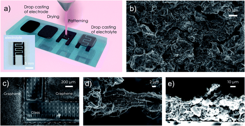
In this work, we report a facile process to fabricate MSCs that can operate at temperatures up to 150 °C with good cycle lifetime and high areal capacitance over 10 mF cm−2. The fabrication of the MSC electrodes relies on our previously reported high-concentration aqueous inks of activated graphene.18 In contrast to many other graphene inks, which often use polymeric binders for stabilization,15,16 our activated graphene inks use graphene oxide as the surfactant, fumed silica as the rheology modifier, and carbon nanotubes (CNTs) as the conductive binder to improve mechanical and electrical contacts between the grains of activated graphene. The electrically insulating graphene oxide is reduced to conductive reduced graphene oxide (rGO) after the post-deposition annealing to further improve the electrical conductivity. It is important to note that all the additives (rGO, CNTs and fumed silica) and the activated graphene have excellent thermal stability at high temperatures over 400 °C, which offers great opportunities for us to fabricate stable electrodes for high-temperature MSCs. In particular, the obtained highly concentrated (20 mg mL−1), viscous (over 104 Pa s) and stable water-based activated graphene inks18,19 enable us to fabricate high-performance MSCs through four simple steps: (1) drop casting of electrode materials, (2) drying and annealing, (3) direct laser patterning through laser scribing, and (4) drop casting of electrolytes, as illustrated in Fig. 1a. The high viscosity and high concentration of the graphene inks make it convenient to fabricate uniform thick (in the range of 25–50 μm, Fig. 1e and S2†) graphene electrode films with a sheet resistance of 9.3 Ω sq−1 simply through drop casting. In practice, to further improve the patternability, a small amount (10 mg mL−1) of sacrificial viscosifier, xanthan gum, was added to the activated graphene inks to further increase the ink viscosity. After the ink dried, the obtained electrode films were annealed at 300 °C in air for 30 minutes to remove the xanthan gum, reduce the graphene oxide and enhance the thermal stability of the electrodes. Afterwards, direct laser scribing was used to pattern the electrode films into interdigitated structures (Fig. 1a and c) with a finger width of 1 mm, an inter-finger gap of 500 μm and a total footprint area of 0.6 cm2 (including the gap region). Finally, an ionogel based on a mixture of poly(vinylidenefluoride-co-hexafluoropropylene) (PVDF-HFP) and a RTIL, 1-butyl-3-methylimidazolium tetrafluoroborate (BMIM-BF4) in acetone was drop cast onto the electrodes to form the final MSCs, benefiting from the good thermal stability of both PVDF-HFP and BMIM-BF4. The details of the device fabrication are described in the ESI.†
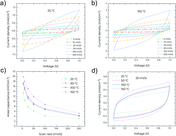
To study the thermal stability of the MSCs, high temperature measurements were performed on a Signatone S-1060R 4′′ Hot Chuck with a temperature accuracy of 1 °C. Cyclic voltammetry (CV), electrochemical impedance spectroscopy (EIS) and galvanostatic charge–discharge (GCD) analyses were performed and measured at 25, 50, 100 and 150 °C, respectively. Fig. 2a shows the CV curves for the MSCs at scan rates ranging from 5 to 250 mV s−1 at 25 °C. The device exhibits rectangular profiles at low scan rates <50 mV s−1, indicating the electrical double layer capacitive behaviour. However, at high scan rates >100 mV s−1, the CV profile becomes lens-like. The relatively high series resistance degrades the device performance at high scan rates. In contrast, as shown in Fig. 2b, the CV curves at 150 °C retain good rectangularity even at high scan rates, pointing to the capability of the MSCs working at temperatures as high as 150 °C and with higher performance. Fig. 2c presents the areal capacitance measured at different temperatures and scan rates and clearly confirms the increase of areal capacitance with increasing temperature. Remarkably, a high areal capacitance of about 20 mF cm−2 is obtained for the MSCs operating at 150 °C and at a scan rate of 5 mV s−1. This performance is even superior to many MSCs reported recently that can only operate at low temperature <60 °C. The high areal capacitance is related to the very high surface area (∼2700 m2 g−1) of the precursor activated graphene.18 The temperature-dependent areal capacitance is also confirmed in Fig. 2d where the rectangular CV profile (measured at a scan rate of 25 mV s−1) enlarges with the increase of temperature. In general, the ionic conductivity of the gel electrolyte increases with temperature due to the reduced viscosity and follows the Arrhenius-type thermally activated behavior,20 which is likely the cause of an increase in areal capacitance with increasing operating temperature of the MSCs.
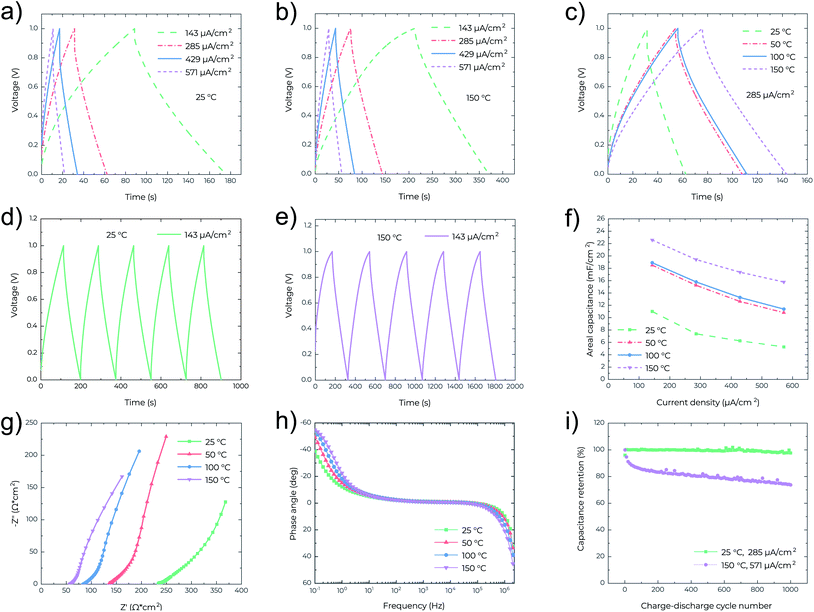
In Fig. 3a–e the nearly symmetrical and triangular profile of the GCD curves at different current densities and temperatures confirms the electrical double layer behaviour of the MSCs. For the given current densities, the discharge times are increased almost twice when the operating temperature increases from 25 °C (Fig. 3a) to 150 °C (Fig. 3b), as also confirmed in Fig. 3c. In Fig. 3c, at the same current density, the IR drop also decreases from 0.13 V at 25 °C to 0.04 V at 150 °C, confirming again the reduced resistance of the MSCs at high temperature. Fig. 3f shows that the areal capacitance significantly increases with temperature, consistent with the results obtained from the CV analysis (Fig. 2c). The highest capacitance of 22.5 mF cm−2 was attained at 150 °C and measured at a current density of 143 μA cm−2. EIS characterization was also performed to analyze the capacitive behavior of the MSCs. In Fig. 3g, the Nyquist plots indicate that the series resistance of the MSC decreases with temperature from 233 ohm cm2 at 25 °C to 57 ohm cm2 at 150 °C. At the low-frequency region, the Nyquist plots are nearly vertical at all temperatures indicating ideal capacitive behavior, while at the mid-frequency region, the parts for the 45° Warburg-type impedance element shrink with the increasing temperature, which implies fast ion diffusion at high temperature.21,22 In Fig. 3h the Bode phase plots also show that the characteristic frequency (at which the impedance phase angle is −45°)15 increases with temperature, confirming lower series resistance and hence higher electrochemical performance of the MSC at high temperature. Fig. 3i outlines the cycling behaviour of MSCs at different temperatures. After 1000 cycles, 97.6% of the capacitance is retained at 25 °C and 73.7% at 150 °C. It is worth mentioning that most probably this is the first demonstration of the cycling performance of MSCs at a high temperature of 150 °C. The relatively poor cycling performance (73.7% capacitance retention after 1000 cycles) is likely due to the limited thermal stability of PVDF-HFP in the electrolyte. Another important reason is that the cycling test at 150 °C is at a high current density of 571 μA cm−2.
To further underline the thermal stability of the MSCs, the cycling performance against temperature change was also studied. Fig. 4a shows the recoverability of the device performance upon one cycle of temperature change at different scan rates. It is clear that at all scan rates the areal capacitance increases with temperature, and returns to the initial values once the MSCs cool down. This indicates high repeatability of the device performance with the temperature change in any direction. Fig. 4b presents the repeatability of the areal capacitance after 5 full temperature cycles (each cycle consists of a temperature increase from 25 °C to 150 °C and a following cooling down from 150 °C to 25 °C). After every temperature cycle, the areal capacitance can retain its initial values. This can be confirmed in Fig. 4c where the CV curves are indistinguishable between different temperature cycles. All these verify the excellent performance reliability and thermal stability of the MSCs.
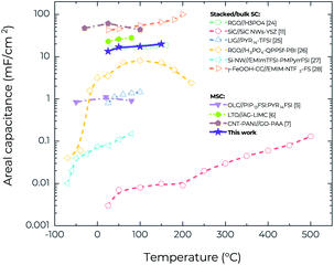
One of the specific features of the RTIL-based electrolytes is their ability to operate within a wide voltage window, which leads to much higher energy density.23 Fig. S5a and b† show the CV curves of the MSCs for a range of voltage windows at 25 °C and 150 °C, respectively. After increasing the voltage window from 1.0 V to 2.0 V, the CV curves retain the good rectangularity. Furthermore, it is possible to increase areal capacitance by increasing the operating voltage window at both 25 °C and 150 °C (Fig. S5c†). At 150 °C, when the voltage window increases from 1.0 V to 2.0 V, the areal capacitance (at a scan rate of 25 mV s−1) increases from 15.1 mF cm−2 to 19.4 mF cm−2, corresponding to an increase of areal energy density from 2.1 μW h cm−2 to 10.8 μW h cm−2, and an increase of areal power density from 0.19 mW cm−2 to 0.49 mW cm−2. However, additional research is still needed to confirm the reliability of the working voltage of 2.0 V at 150 °C because in the GCD characterization (Fig. S6†) it is difficult to charge the devices to 2.0 V at a medium current density of 285 μA cm−2 whereas they can be readily charged to 1.0 V even at a lower current density of 143 μA cm−2 (Fig. 3e). Fig. 5 compares the temperature-dependent areal capacitance of our MSCs with that of other reported planar MSCs and stacked supercapacitors in the literature.5–7,11,24–28 It is clear that our MSCs exhibit both larger areal capacitance (for the values obtained from the voltage window of 1.0 V) and higher operating temperature than most other supercapacitors, in spite of their facile fabrication process.
Conclusions
In conclusion, combining our previously developed ink based on high surface area activated graphene with direct laser scribing and ionogel electrolytes, we have developed a facile technique to fabricate MSCs that can operate at high temperatures up to 150 °C. The devices exhibit good thermal stability under both cyclic charging/discharging test and cyclic temperature change test when charged up to 1.0 V. Likely for the first time, we have demonstrated that the MSCs can be charged and discharged at 150 °C for 1000 cycles with capacitance retention of 74% at a high current density of 571 μA cm−2. At 150 °C, the MSCs can also be readily operated in the voltage window of 1.0 V, resulting in a large areal capacitance of 15.1 mF cm−2, a high areal energy density of over 2 μW h cm−2 and a high areal power density of about 0.2 mW cm−2. The performance is superior to that of most other reported MSCs in the literature that can only operate at low temperatures. Therefore, our MSCs have great potential to serve as the on-chip integrated energy storage components for future electronics that operate in high temperature environments.Conflicts of interest
There are no conflicts to declare.Acknowledgements
Viktoriia Mishukova and Jiantong Li acknowledge the financial support of the Formas Foundation through the Future Research Leaders Grant (No. 2016-00496), the ÅForsk Foundation (Grant No. 17-352), the Olle Engkvist Byggmästare Foundation (Grant No. 2014/799), the Swedish Foundation for International Cooperation in Research and Higher Education (STINT, CH2017-7284), and the Swedish Research Council (Grant No. 2019-04731). Alexandr Talyzin and Nicolas Boulanger acknowledge funding from the European Union's Horizon 2020 research and innovation program under grant agreement No. 785219 and No. 881603. Alexandr Talyzin acknowledges support from the Swedish Research Council grant (No. 2017-04173).References
- J. Watson and G. Castro, J. Mater. Sci.: Mater. Electron., 2015, 26, 9226–9235 CrossRef CAS.
- C.-M. Zetterling, A. Hallén, R. Hedayati, S. Kargarrazi, L. Lanni, B. G. Malm, S. Mardani, H. Norström, A. Rusu, S. S. Suvanam, Y. Tian and M. Östling, Semicond. Sci. Technol., 2017, 32, 034002 CrossRef.
- X. Lin, M. Salari, L. M. R. Arava, P. M. Ajayan and M. W. Grinstaff, Chem. Soc. Rev., 2016, 45, 5848–5887 RSC.
- N. A. Kyeremateng, T. Brousse and D. Pech, Nat. Nanotechnol., 2017, 12, 7–15 CrossRef CAS PubMed.
- P. Huang, D. Pech, R. Lin, J. K. Mcdonough, M. Brunet, P.-L. Taberna, Y. Gogotsi and P. Simon, Electrochem. Commun., 2013, 36, 53–56 CrossRef CAS.
- S. Zheng, J. Ma, Z.-S. Wu, F. Zhou, Y.-B. He, F. Kang, H.-M. Cheng and X. Bao, Energy Environ. Sci., 2018, 11, 2001–2009 RSC.
- X. Jin, G. Zhang, G. Sun, H. Yang, Y. Xiao, J. Gao, Z. Zhang, L. Jiang and L. Qu, Nano Energy, 2019, 64, 103938 CrossRef.
- B. E. Conway, Electrochemical Supercapacitors, Springer US, Boston, MA, 1999, p. 698 Search PubMed.
- S. Zheng, X. Shi, P. Das, Z.-S. Wu and X. Bao, Adv. Mater., 2019, 31, 1900583 CrossRef CAS PubMed.
- D. E. Glass, J.-P. Jones, A. V. Shevade, D. Bhakta, E. Raub, R. Sim and R. V. Bugga, J. Power Sources, 2020, 449, 227492 CrossRef CAS.
- C. H. Chang, B. Hsia, J. P. Alper, S. Wang, L. E. Luna, C. Carraro, S. Y. Lu and R. Maboudian, ACS Appl. Mater. Interfaces, 2015, 7, 26658–26665 CrossRef CAS PubMed.
- R. S. Borges, A. L. M. Reddy, M.-T. F. Rodrigues, H. Gullapalli, K. Balakrishnan, G. G. Silva and P. M. Ajayan, Sci. Rep., 2013, 3, 2572 CrossRef PubMed.
- S. Zheng, H. Huang, Y. Dong, S. Wang, F. Zhou, J. Qin, C. Sun, Y. Yu, Z.-S. Wu and X. Bao, Energy Environ. Sci., 2020, 13, 821–829 RSC.
- J. Jiang, J. Electrochem. Soc., 2017, 164, H5043–H5048 CrossRef CAS.
- J. Li, F. Ye, S. Vaziri, M. Muhammed, M. C. Lemme and M. Östling, Adv. Mater., 2013, 25, 3985–3992 CrossRef CAS PubMed.
- H. Li and J. Liang, Adv. Mater., 2020, 32, 1805864 CrossRef CAS PubMed.
- S. Sollami Delekta, K. H. Adolfsson, N. Benyahia Erdal, M. Hakkarainen, M. Östling and J. Li, Nanoscale, 2019, 11, 10172–10177 RSC.
- V. Skrypnychuk, N. Boulanger, A. Nordenström and A. Talyzin, J. Phys. Chem. Lett., 2020, 11, 3032–3038 CrossRef CAS PubMed.
- N. Boulanger, V. Skrypnychuk, A. Nordenström, G. Moreno-Fernández, M. Granados-Moreno, D. Carriazo, R. Mysyk, G. Bracciale, P. Bondavalli and A. V. Talyzin, ChemElectroChem, 2021, 8, 1349–1361 CrossRef CAS.
- S. K. C. Shalu, R. K. Singh and S. Chandra, J. Phys. Chem. B, 2013, 117, 897–906 CrossRef CAS PubMed.
- Y. Xia, T. S. Mathis, M. Q. Zhao, B. Anasori, A. Dang, Z. Zhou, H. Cho, Y. Gogotsi and S. Yang, Nature, 2018, 557, 409–412 CrossRef CAS PubMed.
- S. Sollami Delekta, M. M. Laurila, M. Mäntysalo and J. Li, Nano-Micro Lett., 2020, 12, 40 CrossRef PubMed.
- X. Shi, Z.-S. Wu, J. Qin, S. Zheng, S. Wang, F. Zhou, C. Sun and X. Bao, Adv. Mater., 2017, 29, 1703034 CrossRef PubMed.
- S. K. Kim, H. J. Kim, J. C. Lee, P. V. Braun and H. S. Park, ACS Nano, 2015, 9, 8569–8577 CrossRef CAS PubMed.
- P. Zaccagnini, D. di Giovanni, M. G. Gomez, S. Passerini, A. Varzi and A. Lamberti, Electrochim. Acta, 2020, 357, 136838 CrossRef CAS.
- A. Chaichi, G. Venugopalan, R. Devireddy, C. Arges and M. Ranjan Gartia, ACS Appl. Energy Mater., 2020, 2020, 5693–5704 CrossRef.
- R. Newell, J. Faure-Vincent, B. Iliev, T. Schubert and D. Aradilla, Electrochim. Acta, 2018, 267, 15–19 CrossRef CAS.
- B. Shen, R. Guo, J. Lang, L. Liu, L. Liu and X. Yan, J. Mater. Chem. A, 2016, 4, 8316–8327 RSC.
Footnote |
| † Electronic supplementary information (ESI) available. See DOI: 10.1039/d1na00220a |
| This journal is © The Royal Society of Chemistry 2021 |


