DOI:
10.1039/C8FD00001H
(Paper)
Faraday Discuss., 2018,
208, 427-441
Continuous synthesis of hollow silver–palladium nanoparticles for catalytic applications
Received
6th January 2018
, Accepted 27th February 2018
First published on 16th April 2018
Abstract
Hollow bimetallic nanoparticles exhibit unique surface plasmonic properties, enhanced catalytic activities and high photo-thermal conversion efficiencies amongst other properties, however, their research and further deployment are currently limited by their complicated multi-step syntheses. This paper presents a novel approach for their continuous synthesis with controllable and tuneable sizes and compositions. This robust manufacturing tool, consisting of coiled flow inverter (CFI) reactors connected in series, allows for the first time the temporal and spatial separation of the initial formation of silver seeds and their subsequent galvanic displacement reaction in the presence of a palladium precursor, leading to the full control of both steps separately. We have also demonstrated that coupling the galvanic replacement and co-reduction leads to a great kinetic enhancement of the system leading to a high yield process of hollow bimetallic nanoparticles, directly applicable to other metal combinations.
1. Introduction
Palladium nanoparticles have been widely used as catalysts for a variety of reactions including oxidation, hydrogenation, reduction, and C–C coupling, among others.1–3 Moreover, the applications of palladium-based bimetallic nanostructures, e.g. Pt/Pd and Au/Pd, for oxidation and reduction reactions have been widely reported.4–8 Among various metals, silver has been a very promising choice to form Ag–Pd bimetallic nanostructures with improved catalytic performance due to the unique synergistic interaction between Ag and Pd.9 It is well known that the catalytic performance of Ag–Pd NPs strongly depends on their size, composition, surface modification (i.e. surfactants, ligands, and coordinating solvents) and morphology (i.e. hollow and solid). In recent years, bimetallic nanomaterials with hollow structures have also attracted the research focus as they exhibit unique surface plasmonic and catalytic properties, which differ from their non-hollow counterpart structures.10,11 While bimetallic compositions allow for the combination and/or synergy of catalytic properties between their two metal components, their hollow interiors offer enhanced plasmonic properties, higher photo-thermal conversion and higher surface-to-volume ratios relative to solid structures.12,13 The galvanic replacement reaction has emerged as a powerful and versatile route for the synthesis of nanomaterials with hollow structures as the size and morphology of the final product can be readily manipulated by using different types of sacrificial templates and precisely controlling the extent of replacement.14 Ag-based nanocrystals have been frequently used as sacrificial templates to produce Au, Pd, and Pt hollow nanostructures.1,15 However, conventional synthesis of these hollow structures in batch processes presents a number of difficulties to achieve a controlled system, especially in the case of bimetallic nanoparticles due to their multi-step synthetic methods. In addition, the presence of organic stabilizers or ligands, which are usually required in batch processes, limit the size control of the resulting particles as well as potentially interfering during their catalytic applications by blocking their active sites.16 Consequently, reliable synthetic protocols for Ag–Pd bimetallic nanoparticles (NPs) with well-defined and tuneable size, composition, and morphology without any organic stabilizing agent are highly demanded.
In this context, microreactors are presented as a continuous manufacturing platform for the controllable synthesis of nanoparticles.17 Nanoparticles with defined size, composition, and morphology can be synthesized by readily adjusting the operation parameters such as flow rate, reactor length, reactant concentration and reaction temperature. In addition, and even more importantly, we have recently demonstrated that the laminar flow regime characteristic of micro-devices allows the production of nanoparticles in the absence of steric stabilizing agents.18 In this paper, we present a new approach for the synthesis of Ag–Pd bimetallic hollow nanoparticles in a system consisting of a number of coiled flow inverter (CFI) microreactors connected in series. This approach allows the temporal and spatial separation of the formation of silver nanoparticle seeds with controllable sizes and the consequent galvanic replacement reaction in the presence of a palladium precursor. We also demonstrate that the co-presence of hydroquinone as a mild reducing agent during the galvanic displacement step leads to its kinetic enhancement due to the simultaneous co-reduction of silver and palladium. Finally, the 4-nitrophenol reduction reaction was used to show the enhanced catalytic activity of the hollow Ag–Pd bimetallic nanoparticles with respect to the monometallic and solid counterparts.
2. Experimental procedures
Reagents and chemicals used in this work, including silver nitrate solution (AgNO3, 0.1 M), palladium(II) nitrate solution (Pd(NO3)2, 10 wt% in 10 wt% nitric acid, 99.999% trace metals basis), potassium tetrachloropalladate(II) (K2PdCl4, 99.99% trace metals basis), trisodium citrate dihydrate (Na3CA, ≥99%, FG), sodium borohydride powder (NaBH4, ReagentPlus®, 99%), hydroquinone (HQ, ReagentPlus®, ≥99%), sodium borohydride solution (NaBH4, 12 wt% in 14 M NaOH), 4-nitrophenol (4-NP, spectrophotometric grade), and bovine serum albumin (BSA) were all purchased from Sigma-Aldrich and used without further purification. Ultrapure water was obtained using an ELGA Maxima ultra-pure water system (18.2 MΩ cm resistivity).
2.1 Synthesis of Ag–Pd bimetallic nanoparticles
Ag–Pd bimetallic nanoparticles (NPs) were synthesized in coiled flow inverter (CFI) microreactors consisting of PFA tubing (0.03′′ inner diameter and 1/16′′ outer diameter) coiled around a 3D-printed support (printed using a Form 1 + stereolithography printer from FormLabs). 3D printing technology was adopted here to provide a precise control of all the reactor’s geometric parameters, such as helix diameter (1 cm), pitch distance (1/π cm), and tubing length. Syringe pumps (Pump 11 Elite, Harvard Apparatus) were used to introduce the reactants at different points in the system.
Hollow silver–palladium bimetallic nanoparticles were prepared by connecting three CFI microreactors in series. Firstly, silver seed particles were prepared in Reactor 1 at 60 °C by mixing a solution containing a mixture of freshly prepared NaBH4 (0.025 mM) and sodium citrate (0.35 mM) and AgNO3 (0.05 mM). Both solutions were introduced into Reactor 1 at a volumetric flow rate of 0.25 ml min−1 with a residence time of 3 min. The resulting Ag seeds were introduced into Reactor 2 for seed growth at 90 °C by adding a mixture of AgNO3 (2 mM) and Na3CA (14 mM) at a flow rate of 0.025 ml min−1 with a residence time of 3 minutes. Finally, the resulting silver nanoparticles were introduced into Reactor 3 at 60 °C and mixed with 0.125 ml min−1 of a HQ solution (4.725 mM) and 0.0125 ml min−1 of Pd(NO3)2 solution (4.7 mM in HNO3 solution, pH = 2). The residence time in this reactor was 12 min. The resulting Ag![[thin space (1/6-em)]](https://www.rsc.org/images/entities/char_2009.gif) :
:![[thin space (1/6-em)]](https://www.rsc.org/images/entities/char_2009.gif) Pd molar ratio was 1
Pd molar ratio was 1![[thin space (1/6-em)]](https://www.rsc.org/images/entities/char_2009.gif) :
:![[thin space (1/6-em)]](https://www.rsc.org/images/entities/char_2009.gif) 4 and the Pd
4 and the Pd![[thin space (1/6-em)]](https://www.rsc.org/images/entities/char_2009.gif) :
:![[thin space (1/6-em)]](https://www.rsc.org/images/entities/char_2009.gif) HQ molar ratio was 1
HQ molar ratio was 1![[thin space (1/6-em)]](https://www.rsc.org/images/entities/char_2009.gif) :
:![[thin space (1/6-em)]](https://www.rsc.org/images/entities/char_2009.gif) 10.
10.
In order to gain further understanding of the synthesis of hollow Ag–Pd nanoparticles, the simultaneous reduction of both metals was carried out in a single CFI reactor. For this, a silver precursor solution (0.061 mM AgNO3 and 0.427 mM Na3CA), Pd(NO3)2 solution (4.7 mM in HNO3 solution, pH = 2) and HQ solution (49.5 mM) were mixed simultaneously with volumetric flow rates of 0.25 ml min−1, 0.125 ml min−1 and 0.125 ml min−1, respectively. The reaction temperature was controlled at 60 °C and the residence time in Reactor 1 was 12 minutes. Final concentrations of Ag, Pd, and HQ were, respectively, 0.056 mM, 0.225 mM and 2.25 mM.
2.2 Reduction of 4-nitrophenol in aqueous solution
The catalytic activities of synthesized Ag–Pd bimetallic nanoparticles were evaluated using the reduction of 4-nitrophenol with NaBH4 as a model reaction.19 The reaction was carried out in 4.5 ml cuvettes with a path length of 1 cm. The total volume was fixed as 3 ml with 1 ml 4-nitrophenol concentration of 10−4 M and 2 ml NaBH4 concentration of 10−1 M. The reaction concentrations of 4-NP and NaBH4 were 3.3 × 10⁻⁵ M and 6.6 × 10⁻² M, respectively. The reaction was started with the addition of 5 μl of as-prepared nanoparticles at room temperature. Immediately after particle addition, time-dependent ultraviolet-visible (UV-vis) absorbance spectra were recorded with a time interval of 8 seconds. The background correction was done with deionized water as reference.
2.3 Characterization methods
Ultraviolet-visible spectroscopy measurements were performed on an Agilent Cary 60 UV-vis spectrophotometer in the wavelength range from 200 to 800 nm, with a resolution of 1 nm. Transmission electron microscopy (TEM) images, EDX spectra and EDX line-scan profiles were obtained using a FEI Tecnai 20 transmission electron microscope (STEM mode) with a spot size of 6 and a resolution <2 nm. Specimens for TEM analysis were prepared according to Michen et al.’s protocol20 to avoid post-synthesis agglomeration.
3. Results and discussion
The synthesis of hollow Ag–Pd bimetallic nanoparticles was carried out using coiled flow inverter (CFI) microreactors connected in series as illustrated in Fig. 1. The first two reactors in the system were used for the synthesis and growth respectively of silver nanoparticles used as seeds for the formation of Ag–Pd bimetallic particles in Reactor 3.
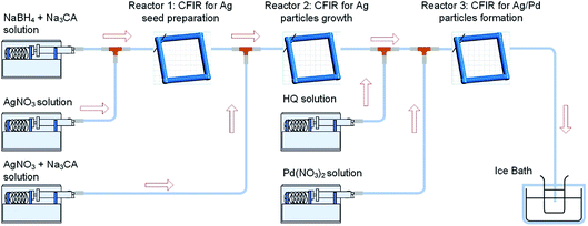 |
| | Fig. 1 Synthesis of hollow Ag–Pd bimetallic nanoparticles using CFI reactors connected in series. | |
We have recently demonstrated the continuous synthesis of narrow sized silver nanoparticles in the absence of organic capping ligands by exploiting the advantages of the laminar flow and the promotion of gentle secondary flows (Lagrarian turbulence) in helical reactors.18 NaBH4 was used in Reactor 1 as a strong reducing agent of AgNO3 to promote a fast nucleation, leading to the formation of small particles with narrow size distribution thanks to the fluid dynamics within the helical reactors. We have also recently shown that selective growth of the seeds requires a drastic change in the chemical environment in Reactor 2 and the complete consumption of NaBH4 in the first reactor to avoid secondary nucleation and consequently a broad size distribution of particles.21 Thus, the NaBH4![[thin space (1/6-em)]](https://www.rsc.org/images/entities/char_2009.gif) :
:![[thin space (1/6-em)]](https://www.rsc.org/images/entities/char_2009.gif) AgNO3 ratio in Reactor 1 was optimised as 1
AgNO3 ratio in Reactor 1 was optimised as 1![[thin space (1/6-em)]](https://www.rsc.org/images/entities/char_2009.gif) :
:![[thin space (1/6-em)]](https://www.rsc.org/images/entities/char_2009.gif) 2 to ensure the synthesis of narrow sized silver seeds and the full consumption of NaBH4 by silver reduction and hydrolysis, reactions (1) and (2), respectively.
2 to ensure the synthesis of narrow sized silver seeds and the full consumption of NaBH4 by silver reduction and hydrolysis, reactions (1) and (2), respectively.
| | | 8Ag+ + BH4− + 8OH− → 8Ag + H2BO3− + 5H2O | (1) |
| | | BH4− + 2H2O → BO2− + 4H2 | (2) |
Due to the absence of organic capping ligands, Na3CA was added in Reactor 1 to stabilize the silver seeds electrostatically. It is important to note that under these conditions (60 °C), sodium citrate does not reduce silver, however, it releases OH− ions due its dissolution in water (reaction (3)), increasing the pH of the solution and promoting the nucleation by NaBH4 (reaction (1)).
| | | C6H5O73− + H2O ↔ C6H6O72− + OH− | (3) |
In this way, silver seeds with particle size of 5.4 ± 1.0 nm (Fig. 2a–c) were synthesized in Reactor 1 at 60 °C with a AgNO3![[thin space (1/6-em)]](https://www.rsc.org/images/entities/char_2009.gif) :
:![[thin space (1/6-em)]](https://www.rsc.org/images/entities/char_2009.gif) NaBH4
NaBH4![[thin space (1/6-em)]](https://www.rsc.org/images/entities/char_2009.gif) :
:![[thin space (1/6-em)]](https://www.rsc.org/images/entities/char_2009.gif) Na3CA ratio of 2
Na3CA ratio of 2![[thin space (1/6-em)]](https://www.rsc.org/images/entities/char_2009.gif) :
:![[thin space (1/6-em)]](https://www.rsc.org/images/entities/char_2009.gif) 1
1![[thin space (1/6-em)]](https://www.rsc.org/images/entities/char_2009.gif) :
:![[thin space (1/6-em)]](https://www.rsc.org/images/entities/char_2009.gif) 7. These initial seeds were grown in Reactor 2 at 90 °C adopting a seed mediated method by mixing with additional AgNO3 solution (2 mM) and using Na3CA as mild reducing agent to avoid secondary nucleation. Ag NPs with particle size of 9.4 ± 1.8 nm were synthesised in Reactor 2 (Fig. 2d–f). The Ag NPs’ size can be tuned by readily changing the concentration of AgNO3 added in Reactor 2.21
7. These initial seeds were grown in Reactor 2 at 90 °C adopting a seed mediated method by mixing with additional AgNO3 solution (2 mM) and using Na3CA as mild reducing agent to avoid secondary nucleation. Ag NPs with particle size of 9.4 ± 1.8 nm were synthesised in Reactor 2 (Fig. 2d–f). The Ag NPs’ size can be tuned by readily changing the concentration of AgNO3 added in Reactor 2.21
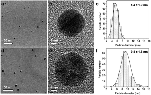 |
| | Fig. 2 TEM and HRTEM images and the corresponding particle size distribution histogram of Ag nanoparticles formed in Reactor 1 (a–c) and after growth in Reactor 2 (d–f). | |
3.1 K2PdCl4 as palladium precursor
After the synthesis of narrow sized silver nanoparticles, a palladium precursor was introduced in Reactor 3 to promote the galvanic displacement of silver and, thus, the formation of hollow nanoparticles. We started our investigations by using K2PdCl4 as the palladium precursor, commonly used for this type of galvanic reaction where silver nanoparticles are re-dissolved facilitating the reduction of palladium. The structural variation taking place in Reactor 3 could be verified by monitoring the absorption spectrum of the solution as the characteristic surface plasmon resonance bands of the Ag NPs and Ag–Pd NPs are sensitive to changes in the composition of the particles. Indeed, after adding (PdCl4)2− and HQ in Reactor 3, the absorbance peak at ∼390 nm corresponding to the Ag seeds formed in Reactor 2 disappeared and new absorption peaks around 246 nm and 288 nm appear, characteristic of Ag–Pd NPs and HQ in solution respectively as shown in Fig. 3. It is important to note that the standard electrode potential of PdCl42−/Pd (0.591 V vs. SHE) is lower than that of Ag+/Ag (0.800 V vs. SHE), and consequently reaction (4) is not allowed energetically at ambient temperature.| | | 2Ag(s) + PdCl4(aq)2− → Pd(s) + 2Ag(aq)+ + 4Cl(aq)− | (4) |
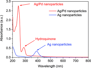 |
| | Fig. 3 UV-vis spectra of Ag nanoparticles formed after Reactor 2 and Ag–Pd bimetallic nanoparticles formed in Reactor 3 using K2PdCl4 as precursor. | |
However, PdCl42− ions can be thermally decomposed at high temperatures (e.g. 60 °C) into Pd2+ and Cl− allowing reaction (5) to take place due to the higher standard electrode potential of Pd2+/Pd (0.951 V vs. SHE).
| | | 2Ag(s) + Pd(aq)2+ → Pd(s) + 2Ag(aq)+ | (5) |
As the galvanic displacement reaction (5) takes place in the presence of HQ, additional reduction of Pd2+ and re-dissolved Ag+ takes place simultaneously, further promoting the galvanic displacement reaction and leading to bimetallic particles through alloying and dealloying reactions (6–8).
| | | Agx(s) + yPd(s) → AgxPdy(s) (alloying) | (6) |
| | | AgxPdy(s) + zPd(s) → AgxPdy+z(s) (alloying) | (7) |
| | | AgxPdy(s) + Pd(aq)2+ → Agx−2Pdy+1(s) + 2Ag(aq)+ (dealloying) | (8) |
In addition, re-dissolved Ag+ can rapidly react with Cl− ions to form AgCl precipitates following reaction (9), insoluble under the studied conditions.
| | | AgCl(s) + Cl(aq)− → AgCl(aq)2− | (9) |
Fig. 4 shows representative microscopy pictures of the resulting nanoparticles after Reactor 3 when K2PdCl4 is used as the palladium precursor. Although some hollow Ag–Pd NPs were observed as depicted in Fig. 4b, most particles seemed to be solid, likely due to the formation of AgCl precipitates covering the surface of Ag–Pd NPs. The formation of AgCl, previously observed in galvanic displacement reactions, is normally removed by re-dissolving it by addition of concentrated NaCl solutions22,23 However, in our system, due to the absence of organic capping ligands, addition of NaCl would strongly modify the ionic strength of the solution leading to agglomeration of the particles.
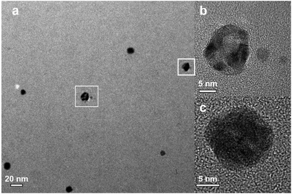 |
| | Fig. 4 (a) TEM image for Ag–Pd bimetallic NPs, (b) HRTEM image for hollow Ag–Pd NPs, and (c) HRTEM image for solid Ag–Pd NPs. | |
3.2 Pd(NO3)2 as palladium precursor
In order to avoid the formation of AgCl, Pd(NO3)2 was used as an alternative palladium precursor in Reactor 3 where the galvanic displacement reaction (5) is favourable as well as the alloying and dealloying reactions (6–8). Similarly to the above observations, after addition of Pd(NO3)2 and HQ in Reactor 3, the absorbance peak at 402 nm characteristic of the Ag seeds formed after Reactor 2 disappeared, while a new sharp absorbance peak at around 246 nm appeared, characteristic of Ag–Pd nanoparticles as shown in Fig. 5. It is important to highlight the large increase in absorbance of the Ag–Pd nanoparticles, characteristic of hollow structures13 with respect to solid particles.
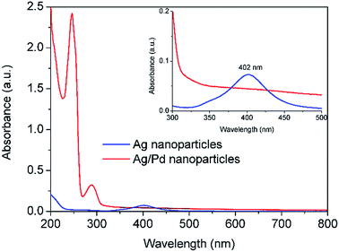 |
| | Fig. 5 UV-vis spectra of Ag nanoparticles after Reactor 2 and Ag–Pd bimetallic nanoparticles after Reactor 3 when Pd(NO3)2 is used as precursor. All the solutions were diluted 12 times. | |
Fig. 6 shows the representative transmission electron microscopy (TEM) and high resolution transmission electron microscopy (HRTEM) images of the prepared Ag–Pd nanoparticles using Pd(NO3)2 as precursor, showing an average diameter of 14.6 ± 2.0 nm. It can be observed that most Ag–Pd NPs present a hollow structure due to the galvanic reaction (5). The well-resolved fringes with a lattice spacing of 2.30 Å shown in Fig. 6c can be indexed to the {111} planes of Ag–Pd alloy.
 |
| | Fig. 6 (a–c) TEM and HTEM images of Ag–Pd hollow NPs (after Reactor 3) synthesised using Pd(NO3)2 as precursor. | |
The distribution of Ag and Pd in random hollow NPs (Fig. 7) was explored by both EDS mapping and line-scan analysis through STEM-EDS. EDS element mapping (Fig. 7c and d) shows that Ag and Pd atoms were well-distributed over the hollow nanospheres with a higher concentration of palladium in agreement with the high Pd![[thin space (1/6-em)]](https://www.rsc.org/images/entities/char_2009.gif) :
:![[thin space (1/6-em)]](https://www.rsc.org/images/entities/char_2009.gif) Ag ratio of 4
Ag ratio of 4![[thin space (1/6-em)]](https://www.rsc.org/images/entities/char_2009.gif) :
:![[thin space (1/6-em)]](https://www.rsc.org/images/entities/char_2009.gif) 1 as indicated by the higher intensity of the Pd (cps) than the Ag mapping. The Ag–Pd alloy composition of the shell is also supported by the EDS line-scan result (Fig. 7b), where one can observe that the total metal (Ag and Pd) intensity decreases in the centre of the particle with two peaks at the edges in agreement with its hollow structure.
1 as indicated by the higher intensity of the Pd (cps) than the Ag mapping. The Ag–Pd alloy composition of the shell is also supported by the EDS line-scan result (Fig. 7b), where one can observe that the total metal (Ag and Pd) intensity decreases in the centre of the particle with two peaks at the edges in agreement with its hollow structure.
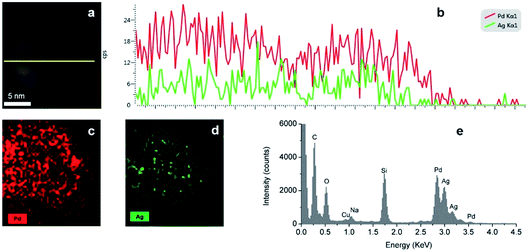 |
| | Fig. 7 (a and b) EDS line scan of the Ag–Pd hollow NPs, (c and d) EDS elemental mapping of Ag–Pd hollow NPs, (e) EDS spectra of the Ag–Pd hollow NPs after Reactor 3 using Pd(NO3)2 as precursor. | |
3.3 Separation of galvanic displacement and reduction steps in Reactor 3
In order to gain further insights into the effect of coupling the galvanic displacement and co-reduction reactions, an additional CFI microreactor was added into the system described above. The configuration set up is shown in Fig. 8. In this case, silver seeds with average size of 9.4 ± 1.8 nm were formed in Reactors 1 and 2 as described before. However, only Pd(NO3)2 was added into Reactor 3 (residence time 12 min, 60 °C) and HQ was added in the new Reactor 4 (residence time 12 min, 60 °C) to separate the galvanic displacement reaction from further reduction. The concentrations and flow rate of reactants were kept equal to the previous systems in all cases. The UV-vis spectra after Reactors 2, 3 and 4 are shown in (Fig. 9). When Pd(NO3)2 was introduced in Reactor 3, the galvanic replacement reaction (5) took place as indicated by the disappearance of the absorbance peak at 402 nm characteristic of the Ag seeds formed in Reactor 2. The appearance of a new peak at 225 nm is due to the Pd(NO3)2 unreacted in solution, however, the shoulder of this peak is likely to be caused by the presence of Pd nanoparticles with absorbance at ∼240 nm. As these particles have a hollow structure, their extinction coefficient is larger than their solid counterparts.13 Finally, when HQ was added in Reactor 4, a clear Ag–Pd NP absorbance peak at 246 nm appears. It is important to note that this absorbance peak is not as sharp as the one observed in the previous case where the galvanic displacement reaction and the HQ reduction took place simultaneously from the beginning in Reactor 3 suggesting that re-reduction of Ag+ ions promotes the galvanic displacement kinetics considerably quicker than the reduction of Pd2+ by HQ. In addition, the Ag–Pd peak is much broader than in Fig. 5 with a clear shoulder at ∼225 nm due to the incomplete reduction of the Pd(NO3)2 precursor. Even when HQ is added in Reactor 4, the nucleation and reduction of Ag is so slow under these conditions that incomplete conversions were achieved at similar residence times.
 |
| | Fig. 8 Synthesis of hollow Ag–Pd bimetallic nanoparticles using CFI reactors connected in series for the separation of the galvanic displacement and co-reduction steps. | |
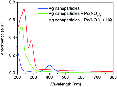 |
| | Fig. 9 UV-vis spectra of Ag seeds after Reactor 2, Pd nanoparticles after galvanic displacement in Reactor 3 and Ag–Pd bimetallic nanoparticles after addition of HQ in Reactor 4. All solutions were diluted 10 times prior to characterisation. | |
Fig. 10 shows characteristic images of the particles where the galvanic displacement and the reduction reactions were separated in reactors connected in series. The particles, formed in Reactor 4 after addition of HQ, present a very broad size distribution with few scattered hollow particles and a large number of monometallic particles, judging from their small size and the d-spacing value, matching with the Ag〈111〉 lattice plane.
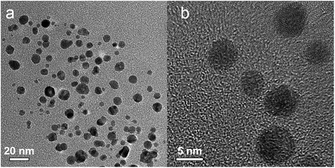 |
| | Fig. 10 (a) TEM and (b) HRTEM images of nanoparticles synthesised using only Pd(NO3)2 in Reactor 3 and HQ in Reactor 4. | |
3.4 Simultaneous reduction of silver and palladium
Further understanding of the formation of the hollow bimetallic nanoparticles was gained by carrying out a simultaneous reduction of Ag(NO3) and Pd(NO3)2 by HQ in a single reactor at 60 °C as depicted in Fig. 11.
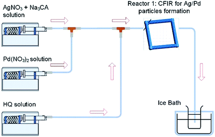 |
| | Fig. 11 Simultaneous reduction of Ag(NO3) and Pd(NO3)2 with HQ in a CFI microreactor. | |
Similarly to above, the product was characterised by UV-vis spectroscopy. Fig. 12 shows the appearance of two absorbance peaks at 288 nm and 246 nm assigned to Ag–Pd nanoparticles and HQ in solution, respectively. Negligible absorbance at ∼400 nm was observed indicating that monometallic silver NPs were not formed under these conditions. The saturation of the detector at low wavelengths (<230 nm) was due to the presence of Pd(NO3)2 as the conversion under these conditions is quite low due to the mild reduction nature of HQ.
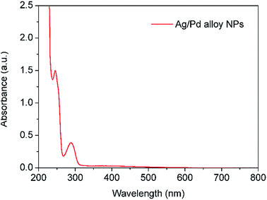 |
| | Fig. 12 UV-vis spectrum of Ag–Pd alloy NPs synthesized by simultaneous reduction of Ag(NO3) and Pd(NO3)2 with HQ. The solution was diluted for 10 times prior to characterisation. | |
Fig. 13 shows images of the Ag–Pd NPs synthesized by simultaneous reduction of Ag(NO3) and Pd(NO3)2 by HQ in a CFI reactor. A very broad distribution of the particles can be observed, with an average diameter of 26.6 ± 8.4 nm caused by the absence of capping ligands in the system and the weak reducing nature of HQ, which leads to slow nucleation, normally translated into broad distributions, despite the presence of citrate. In addition, in this case, metal fouling of the wall of the reactor was observed very quickly, which also leads to poor control of particle size and size distribution.
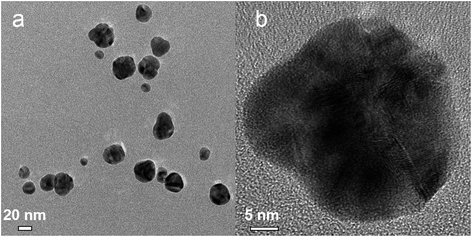 |
| | Fig. 13 (a) TEM and (b) HRTEM image for Ag–Pd alloy NPs synthesized by simultaneous reduction of Ag(NO3) and Pd(NO3)2 with HQ. | |
The formation of a Ag–Pd alloy by simultaneous reduction was confirmed by EDS mapping. As shown in the line scan analysis, the total metal intensity (Pd and Ag) across the particle increases in the middle of the particle in agreement with its solid nature. At the edges of the particle, Pd element has a higher intensity than Ag due to the Pd![[thin space (1/6-em)]](https://www.rsc.org/images/entities/char_2009.gif) :
:![[thin space (1/6-em)]](https://www.rsc.org/images/entities/char_2009.gif) Ag ratio (4
Ag ratio (4![[thin space (1/6-em)]](https://www.rsc.org/images/entities/char_2009.gif) :
:![[thin space (1/6-em)]](https://www.rsc.org/images/entities/char_2009.gif) 1), however, in the centre of the particle, there is a higher presence of Ag, suggesting an Ag rich core. As shown in Fig. 14c and d, Ag and Pd are uniformly dispersed throughout the nanoparticles. Moreover, EDS elemental line scanning of the nanoparticles (Fig. 14b) also verified the presence of the alloy structure in these NPs.
1), however, in the centre of the particle, there is a higher presence of Ag, suggesting an Ag rich core. As shown in Fig. 14c and d, Ag and Pd are uniformly dispersed throughout the nanoparticles. Moreover, EDS elemental line scanning of the nanoparticles (Fig. 14b) also verified the presence of the alloy structure in these NPs.
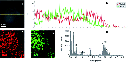 |
| | Fig. 14 (a and b) EDS line scan, (c and d) EDS elemental mapping and (e) EDS spectra of Ag–Pd alloy NPs synthesised by simultaneous reduction of Ag(NO3) and Pd(NO3)2 with HQ. | |
3.5 Catalytic activity in 4-nitrophenol reduction reaction
To evaluate the catalytic performance of the prepared Ag–Pd bimetallic NPs, the reduction of 4-NP reaction was used here as a model reaction (Fig. 15). The absorbance peak of the 4-NP at 400 nm is constant and stable in the absence of a catalyst. Upon the addition of the colloidal particles, the absorbance peak at 400 nm significantly decreased with time and a new peak around 300 nm corresponding to 4-aminophenol (4-AP) gradually developed.
 |
| | Fig. 15 Reduction of 4-nitrophenol to 4-aminophenol, NaBH4 in excess. Conditions: 3.3 × 10⁻⁵ M 4-NP and 6.6 × 10⁻² M NaBH4 at room temperature. | |
A typical evolution of the UV-vis spectra as the reaction time progresses using hollow Ag–Pd NPs synthesized using 3 CFI reactors in series and Pd(NO3)2 as precursor is shown in Fig. 16a. The reduction of 4-NP is considered to be a pseudo-first order reaction with respect to the concentration of 4-NP when an excess of NaBH4 (2000-fold excess in the present study) is used.24 Thus, the rate of consumption of 4-NP, rt, is often defined as:
| |  | (10) |
where
CA is the concentration of 4-NP, and
Kapp is the apparent rate constant in s
−1.
As the absorbance of the solution is proportional to the 4-NP concentration (according to the Beer–Lambert law), simple derivation of eqn (10) leads to a linear correlation between the initial absorbance (A0), the absorbance at a given time (At) and the apparent rate constant (Kapp):
| |  | (11) |
where
C0 is the initial concentration of the 4-NP before Ag–Pd NPs are added and
Ct is the 4-NP concentration at a given time (
t).
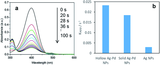 |
| | Fig. 16 (a) Time-dependent UV-vis absorption spectra of the catalytic reduction of 4-nitrophenol to 4-aminophenol by an excess amount of NaBH4 by hollow Ag–Pd NPs synthesised in 3 CFI reactors connected in series, using Pd(NO3)2 as precursor. (b) Average kinetic constant (Kapp) value of hollow alloy Ag–Pd, solid alloy Ag–Pd (synthesised by simultaneous reduction with HQ) and Ag NPs (seeds). | |
Fig. 16b shows the increase of reduction activity of the Ag–Pd nanoparticles with respect to the Ag nanoparticle seeds. It is well known that alloying of Ag–Pd leads to an increase in catalytic activity for a number of reactions such as formic acid decomposition.9 More importantly, hollow Ag–Pd particles present an increase in activity with respect to their solid counterparts, making this continuous synthesis tool a highly attractive tool for the preparation of designer catalysts with controllable morphologies and metal distributions. It is important to mention that the size and polydispersity of the alloy particles is different from the hollow ones and thus, these important factors in addition to the presence of metal salt precursor are likely to affect the absolute catalytic comparison. Further studies related to size control of alloy nanoparticles would be necessary to enable the equal-to-equal comparison.
4. Conclusions and outlook
Hollow bimetallic silver–palladium nanoparticles present an enhanced catalytic activity for the reduction of 4-nitrophenol reaction in comparison to their solid or monometallic counterparts. They can be selectively synthesised in a continuous system consisting of a number of coiled flow inverter (CFI) microreactors connected in series. In this way, the initial formation of silver seeds with tuneable sizes can be separated from the galvanic displacement reaction gaining full control of both steps. The nature of the palladium precursor has a key effect on the system, not only determining the feasibility of the galvanic displacement reaction depending on its reduction potential, but also in the formation of by-products such as AgCl which greatly reduces the yield. Finally, the galvanic displacement reaction can be greatly enhanced in the presence of a mild reducing agent such as hydroquinone.
Conflicts of interest
There are no conflicts to declare.
Acknowledgements
The authors would like to acknowledge the UK Engineering and Physical Science Research Council for funding (grant number EP/L020432/2).
References
- A. G. M. da Silva, T. S. Rodrigues, L. S. K. Taguchi, H. V. Fajardo, R. Balzer, L. F. D. Probst and P. H. C. Camargo, J. Mater. Sci., 2016, 51, 603–614 CrossRef.
- F. C. Walsh, D. V. Bavykin, L. Torrente-Murciano, A. A. Lapkin and B. A. Cressey, Trans. Inst. Met. Finish., 2006, 84, 293–299 CrossRef.
- D. V. Bavykin, A. A. Lapkin, P. K. Plucinski, L. Torrente-Murciano, J. M. Friedrich and F. C. Walsh, Top. Catal., 2006, 39, 151–160 CrossRef.
- T. S. Rodrigues, A. G. M. da Silva, A. Macedo, B. W. Farini, R. d. S. Alves and P. H. C. Camargo, J. Mater. Sci., 2015, 50, 5620–5629 CrossRef.
- R. W. J. Scott, A. K. Datye and R. M. Crooks, J. Am. Chem. Soc., 2003, 125, 3708–3709 CrossRef PubMed.
- D. Wang, A. Villa, F. Porta, L. Prati and D. Su, J. Phys. Chem. C, 2008, 112, 8617–8622 Search PubMed.
- T. Garcia, R. Murillo, S. Agouram, A. Dejoz, M. J. Lazaro, L. Torrente-Murciano and B. Solsona, Chem. Commun., 2012, 48, 5316–5318 RSC.
- L. Torrente-Murciano, Q. He, G. J. Hutchings, C. J. Kiely and D. Chadwick, ChemCatChem, 2014, 6, 2531–2534 CrossRef.
- K. Tedsree, T. Li, S. Jones, C. W. A. Chan, K. M. K. Yu, P. A. J. Bagot, E. A. Marquis, G. D. W. Smith and S. C. E. Tsang, Nat. Nanotechnol., 2011, 6, 302–307 CrossRef PubMed.
- M. Tsuji, Y. Nakashima, A. Yajima and M. Hattori, CrystEngComm, 2015, 17, 6955–6961 RSC.
- X. Xia, Y. Wang, A. Ruditskiy and Y. Xia, Adv. Mater., 2013, 25, 6313–6333 CrossRef PubMed.
- X. W. Lou, L. A. Archer and Z. Yang, Adv. Mater., 2008, 20, 3987–4019 CrossRef.
- J. W. Xiao, S. X. Fan, F. Wang, L. D. Sun, X. Y. Zheng and C. H. Yan, Nanoscale, 2014, 6, 4345–4351 RSC.
- L. Xu, Z. Luo, Z. Fan, S. Yu, J. Chen, Y. Liao and C. Xue, Chem.–Eur. J., 2015, 21, 8691–8695 CrossRef PubMed.
- Y. G. Sun, B. Mayers and Y. N. Xia, Adv. Mater., 2003, 15, 641–646 CrossRef.
- R. Ghosh Chaudhuri and S. Paria, Chem. Rev., 2012, 112, 2373–2433 CrossRef PubMed.
- C.-X. Zhao, L. He, S. Z. Qiao and A. P. J. Middelberg, Chem. Eng. Sci., 2011, 66, 1463–1479 CrossRef.
- K.-J. Wu, G. M. De Varine Bohan and L. Torrente-Murciano, React. Chem. Eng., 2017, 2, 116–128 Search PubMed.
- C. Kästner and A. F. Thünemann, Langmuir, 2016, 32, 7383–7391 CrossRef PubMed.
- B. Michen, C. Geers, D. Vanhecke, C. Endes, B. Rothen-Rutishauser, S. Balog and A. Petri-Fink, Sci. Rep., 2015, 5, 9793 CrossRef PubMed.
- K.-J. Wu and L. Torrente-Murciano, React. Chem. Eng., 2018 10.1039/C7RE00194K.
- M. Tsuji, T. Kidera, A. Yajima, M. Hamasaki, M. Hattori, T. Tsuji and H. Kawazumi, CrystEngComm, 2014, 16, 2684–2691 RSC.
- A.-A. El Mel, M. Chettab, E. Gautron, A. Chauvin, B. Humbert, J.-Y. Mevellec, C. Delacote, D. Thiry, N. Stephant, J. Ding, K. Du, C.-H. Choi and P.-Y. Tessier, J. Phys. Chem. C, 2016, 120, 17652–17659 Search PubMed.
- S. Wunder, F. Polzer, Y. Lu, Y. Mei and M. Ballauff, J. Phys. Chem. C, 2010, 114, 8814–8820 Search PubMed.
|
| This journal is © The Royal Society of Chemistry 2018 |
Click here to see how this site uses Cookies. View our privacy policy here.  Open Access Article
 ,
Yunhu
Gao
and
Laura
Torrente-Murciano
 *
*
![[thin space (1/6-em)]](https://www.rsc.org/images/entities/char_2009.gif) :
:![[thin space (1/6-em)]](https://www.rsc.org/images/entities/char_2009.gif) Pd molar ratio was 1
Pd molar ratio was 1![[thin space (1/6-em)]](https://www.rsc.org/images/entities/char_2009.gif) :
:![[thin space (1/6-em)]](https://www.rsc.org/images/entities/char_2009.gif) 4 and the Pd
4 and the Pd![[thin space (1/6-em)]](https://www.rsc.org/images/entities/char_2009.gif) :
:![[thin space (1/6-em)]](https://www.rsc.org/images/entities/char_2009.gif) HQ molar ratio was 1
HQ molar ratio was 1![[thin space (1/6-em)]](https://www.rsc.org/images/entities/char_2009.gif) :
:![[thin space (1/6-em)]](https://www.rsc.org/images/entities/char_2009.gif) 10.
10.![[thin space (1/6-em)]](https://www.rsc.org/images/entities/char_2009.gif) :
:![[thin space (1/6-em)]](https://www.rsc.org/images/entities/char_2009.gif) AgNO3 ratio in Reactor 1 was optimised as 1
AgNO3 ratio in Reactor 1 was optimised as 1![[thin space (1/6-em)]](https://www.rsc.org/images/entities/char_2009.gif) :
:![[thin space (1/6-em)]](https://www.rsc.org/images/entities/char_2009.gif) 2 to ensure the synthesis of narrow sized silver seeds and the full consumption of NaBH4 by silver reduction and hydrolysis, reactions (1) and (2), respectively.
2 to ensure the synthesis of narrow sized silver seeds and the full consumption of NaBH4 by silver reduction and hydrolysis, reactions (1) and (2), respectively.![[thin space (1/6-em)]](https://www.rsc.org/images/entities/char_2009.gif) :
:![[thin space (1/6-em)]](https://www.rsc.org/images/entities/char_2009.gif) NaBH4
NaBH4![[thin space (1/6-em)]](https://www.rsc.org/images/entities/char_2009.gif) :
:![[thin space (1/6-em)]](https://www.rsc.org/images/entities/char_2009.gif) Na3CA ratio of 2
Na3CA ratio of 2![[thin space (1/6-em)]](https://www.rsc.org/images/entities/char_2009.gif) :
:![[thin space (1/6-em)]](https://www.rsc.org/images/entities/char_2009.gif) 1
1![[thin space (1/6-em)]](https://www.rsc.org/images/entities/char_2009.gif) :
:![[thin space (1/6-em)]](https://www.rsc.org/images/entities/char_2009.gif) 7. These initial seeds were grown in Reactor 2 at 90 °C adopting a seed mediated method by mixing with additional AgNO3 solution (2 mM) and using Na3CA as mild reducing agent to avoid secondary nucleation. Ag NPs with particle size of 9.4 ± 1.8 nm were synthesised in Reactor 2 (Fig. 2d–f). The Ag NPs’ size can be tuned by readily changing the concentration of AgNO3 added in Reactor 2.21
7. These initial seeds were grown in Reactor 2 at 90 °C adopting a seed mediated method by mixing with additional AgNO3 solution (2 mM) and using Na3CA as mild reducing agent to avoid secondary nucleation. Ag NPs with particle size of 9.4 ± 1.8 nm were synthesised in Reactor 2 (Fig. 2d–f). The Ag NPs’ size can be tuned by readily changing the concentration of AgNO3 added in Reactor 2.21


![[thin space (1/6-em)]](https://www.rsc.org/images/entities/char_2009.gif) :
:![[thin space (1/6-em)]](https://www.rsc.org/images/entities/char_2009.gif) Ag ratio of 4
Ag ratio of 4![[thin space (1/6-em)]](https://www.rsc.org/images/entities/char_2009.gif) :
:![[thin space (1/6-em)]](https://www.rsc.org/images/entities/char_2009.gif) 1 as indicated by the higher intensity of the Pd (cps) than the Ag mapping. The Ag–Pd alloy composition of the shell is also supported by the EDS line-scan result (Fig. 7b), where one can observe that the total metal (Ag and Pd) intensity decreases in the centre of the particle with two peaks at the edges in agreement with its hollow structure.
1 as indicated by the higher intensity of the Pd (cps) than the Ag mapping. The Ag–Pd alloy composition of the shell is also supported by the EDS line-scan result (Fig. 7b), where one can observe that the total metal (Ag and Pd) intensity decreases in the centre of the particle with two peaks at the edges in agreement with its hollow structure.


![[thin space (1/6-em)]](https://www.rsc.org/images/entities/char_2009.gif) :
:![[thin space (1/6-em)]](https://www.rsc.org/images/entities/char_2009.gif) Ag ratio (4
Ag ratio (4![[thin space (1/6-em)]](https://www.rsc.org/images/entities/char_2009.gif) :
:![[thin space (1/6-em)]](https://www.rsc.org/images/entities/char_2009.gif) 1), however, in the centre of the particle, there is a higher presence of Ag, suggesting an Ag rich core. As shown in Fig. 14c and d, Ag and Pd are uniformly dispersed throughout the nanoparticles. Moreover, EDS elemental line scanning of the nanoparticles (Fig. 14b) also verified the presence of the alloy structure in these NPs.
1), however, in the centre of the particle, there is a higher presence of Ag, suggesting an Ag rich core. As shown in Fig. 14c and d, Ag and Pd are uniformly dispersed throughout the nanoparticles. Moreover, EDS elemental line scanning of the nanoparticles (Fig. 14b) also verified the presence of the alloy structure in these NPs.


