V5S8–graphite hybrid nanosheets as a high rate-capacity and stable anode material for sodium-ion batteries†
Chenghao
Yang
*a,
Xing
Ou
a,
Xunhui
Xiong
a,
Fenghua
Zheng
a,
Renzong
Hu
b,
Yu
Chen
b,
Meilin
Liu
 ab and
Kevin
Huang
 *c
*c
aNew Energy Research Institute, School of Environment and Energy, South China University of Technology, Guangzhou 510006, P. R. China. E-mail: esyangc@scut.edu.cn; Tel: +86-803-39381203
bSchool of Materials Science & Engineering, Georgia Institute of Technology, Atlanta, GA 30332-0245, USA
cDepartment of Mechanical Engineering, University of South Carolina, Columbia, SC 29205, USA. E-mail: huang46@cec.sc.edu
First published on 28th November 2016
Abstract
Here we report chemically-exfoliated V5S8 and graphite hybrid nanosheets (ce-V5S8–C) as a novel anode material for sodium-ion batteries (SIBs). It exhibits much improved sodiation capacity, rate capability, reversibility and stability compared to other major SIB anode materials.
Broader contextSodium ion batteries (SIBs) are an appealing alternative to lithium ion batteries (LIBs) for large-scale energy storage as sodium is earth abundant and widely accessible. The development of high-performance anode materials is a bottleneck for the success of SIBs. In the present work, we report that monoclinic structured V5S8 nanosheets, when combined with graphite, are a promising anode material for high-performance SIBs. The synthesized V5S8 possesses a unique crystal structure consisting of VS2 monolayer building blocks, between which one-quarter of the available crystallographic sites are occupied by V atoms. Within each VS2 monolayer, VS6 octahedra are face-shared with the adjacent VS6 octahedra centered on the V atoms in the V-partially depleted interlayer. Such a unique structure facilitates the production and transport of electronic/ionic charge carriers, giving an increased electronic/ionic conductivity, and thus promoting a fast three-dimensional (3D) electron and Na+-diffusion transport for reversible charge/discharge cycles. Electrochemical performance results indeed suggest that the V5S8–C hybrid is a promising anode material for SIBs with a good reversible capacity, cycling stability and rate capacity. |
Rechargeable lithium-ion batteries (LIBs) have been widely used in consumer electronics, and are expected to be a major propulsion power for all electric vehicles (AEVs) and/or hybrid electric vehicles (HEVs) soon, and for large-scale energy storage devices for the utility grid in the near future.1,2 However, the unevenly distributed and limited lithium resource on the earth could hinder the full deployment of LIB technology in these areas. Sodium-ion batteries (SIBs) working with the same intercalation chemistry, on the other hand, are considered to be a more sustainable option than LIBs, simply due to the abundance of Na on the earth.3,4 The technical challenge for intercalation chemistry SIBs is, however, the difficulty of accommodating larger Na+ (0.102 nm for Na+vs. 0.076 nm for Li+) in the appropriate hosting electrode materials, as well as the energetic instability of Na+ within the graphene layers of graphite.5,6 This reality has severely limited the use of graphite, an excellent LIB anode, as a practical anode material for SIBs.
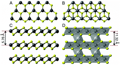
To search for better SIB anode materials, a wide range of compounds including hard carbons,7–10 metals and alloys (Sb, Sn, Se and SnSb),11–14 metal oxides (SnO2 and TiO2)15,16 and transition metal dichalcogenides (TMDs: MoS2, WS2, NbS2, and VS2)17–20 have been extensively investigated in the past. In particular, TMDs have garnered much attention because their layered structure possesses a suitable interlayer spacing to host Na+, thus enabling a better cycle capacity and reversibility.17,20 VS2 is one member of the TMDs family, exhibiting a two-dimensional graphene-like layered structure as shown in Fig. 1A and C, with an interlayer spacing of 0.576 nm, much greater than that of graphite.21–23 The larger interlayer spacing in VS2 offers not only a broad range of electronic properties, but also sufficient room to host Na+. Studies have shown that the VS2 monolayer in a spin-polarized ground state exhibits a superior metallic property and a lower or similar ionic diffusion energy barrier as compared to graphite,21–23 making it a very attractive anode material for SIBs.
However, one of the drawbacks of using VS2 as an SIB anode is the anisotropy in diffusion because of its two-dimensional layered structure, requiring significant engineering effort to ensure good alignment of the crystallographic planes with a diffusional direction in order to maximize the intercalation efficiency.24,25 Here, we report a new three-dimensional compound V5S8 with multiple electronic/ionic pathways as a promising SIB anode material. To the best of our knowledge, this is the first report of testing V5S8 as an SIB anode. The electrochemical performance of SIB using V5S8-based anodes has been extensively characterized, and in situ X-ray diffraction (XRD) along with ex situ high resolution transmission microscopy (HRTEM), X-ray photoemission spectroscopy (XPS) and XRD have also been utilized to assist in the understanding of the underlying enhancement mechanisms.
The crystal structure of V5S8 is illustrated in Fig. 1B and D, which can be characterized as a superstructure consisting of ordered V vacancies in a NiAs-type structure according to early superconductors studies.26–28 Specifically, the structure contains VS2 monolayer building blocks alternating with extra V-atoms partially occupying one-quarter of the available sites between the monolayers (vacant V and occupied V are denoted as VI and VII, respectively). From this structural feature, the formula of V5S8 can, therefore, be written as V0.25VS2. Furthermore, as illustrated in Fig. 1D, the VIIS6 octahedra have the common edges in the V-atoms fully occupied monolayers, while the VI atoms in the V-atoms partially occupied interlayers have the same local symmetry as the VII atoms in the V-atoms fully occupied monolayers. The octahedra in the V-atoms fully occupied monolayers are linked to the VIS6 octahedra in the V-atoms partially filled interlayers via common faces. Since the VIIS6 octahedra linking the two adjacent VS2 monolayers can provide additional pathways for electronic/ionic charge carriers, an enhanced electronic/ionic conductivity along the c-axis (perpendicular to the VS2 monolayers) is expected.29,30
There are three types of V5S8 based materials evaluated in this study as SIB anodes in addition to the baseline chemically exfoliated VS2 (denoted as ce-VS2): bulk V5S8 (denoted as b-V5S8), chemically exfoliated V5S8 (denoted as ce-V5S8) and ce-V5S8/graphite hybrid (denoted as ce-V5S8–C). The synthesis details for these materials are given in the ESI.† The phase compositions of these materials are shown in Fig. S5 of the ESI.† The morphological features of the ce-V5S8 and ce-V5S8–C hybrids are shown in Fig. 2, whereas those of the less interesting b-V5S8 are given in Fig. S8 (ESI†) for comparison. From Fig. 2A and C, ce-V5S8 is clearly seen to consist of flake-like nanosheets. Meanwhile, Fig. 2B and D show that the ce-V5S8–C hybrid exhibits a similar morphology consisting of nanoscaled sheets. The HRTEM images in Fig. 2E and F near the edges of the V5S8 nanosheets reveal that the number and thickness of nanosheets in ce-V5S8 and ce-V5S8–C are 12–15 and 6.79–8.49 nm, respectively, as indicated by the alternating dark and bright patterns. Moreover, the interlayer spacing in the edge area is found to be 0.57 nm, corresponding to the (002) plane of V5S8 (JCPDS: 81-1596, d = 0.566 nm). The selected area electron diffraction (SAED) patterns of ce-V5S8 shown in Fig. 2G and for ce-V5S8–C shown in Fig. 2H can be indexed to the monoclinic structure of V5S8, where the diffraction rings can be indexed to the (002), (220), (222), (![[2 with combining macron]](https://www.rsc.org/images/entities/char_0032_0304.gif) 24) and (513) planes of the structure, respectively. For comparison, the microstructure of chemically exfoliated VS2 (ce-VS2) has also been shown in Fig. S10 (ESI†), where the ce-VS2 exhibits a flower-like morphology (Fig. S10A, ESI†), and a high magnification SEM image indicates that the ce-VS2 microflowers consist of VS2 nanosheets with a thickness of ∼10–15 nm.
24) and (513) planes of the structure, respectively. For comparison, the microstructure of chemically exfoliated VS2 (ce-VS2) has also been shown in Fig. S10 (ESI†), where the ce-VS2 exhibits a flower-like morphology (Fig. S10A, ESI†), and a high magnification SEM image indicates that the ce-VS2 microflowers consist of VS2 nanosheets with a thickness of ∼10–15 nm.
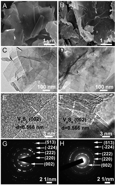 | ||
| Fig. 2 SEM, TEM, HRTEM images and SAED patterns of ce-V5S8 nanosheets (A, C, E and G) and ce-V5S8–C hybrids (B, D, F and H), respectively. | ||
It is worth pointing out that the graphite in the ce-V5S8–C hybrid overcoats the outer surface of ce-V5S8. This is indirectly evidenced by the lower transparency shown in Fig. 2D than in Fig. 2C, and directly evidenced by the XPS analysis shown in Fig. S21 (ESI†), the HRTEM image shown in Fig. S22 (ESI†), and the EDS mapping shown in Fig. S9 (ESI†), where V, S and C are homogeneously distributed in the ce-V5S8–C nanosheets. The thin C-layer is deemed multifunctional, which will be further discussed in the following.
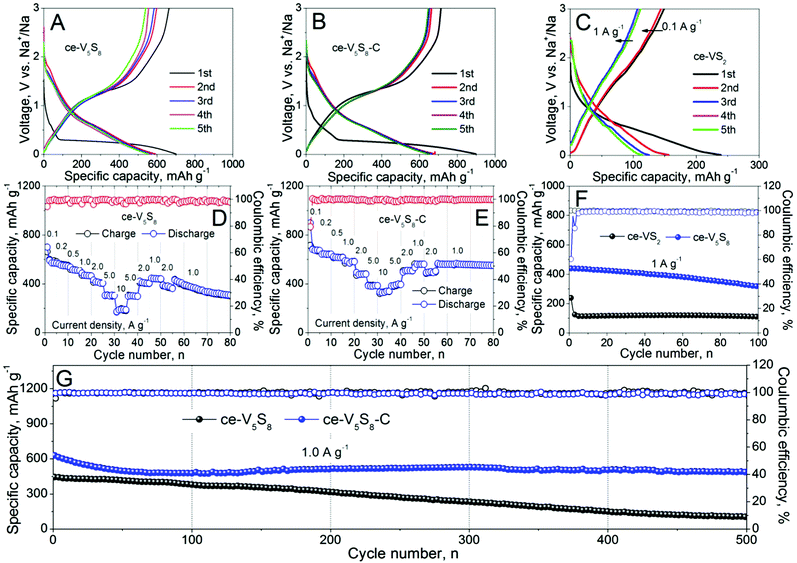
The electrochemical performances of ce-VS2, ce-V5S8 and ce-V5S8–C as SIB anodes are compared in Fig. 3. It is evident from Fig. 3A that ce-V5S8 displays an initial discharge capacity of 701 mA h g−1 at a current density of 0.1 A g−1, compared to 241 mA h g−1 of ce-VS2 at the same current density, as shown in Fig. 3C. In the subsequent cycles, the charge–discharge profiles of ce-V5S8 do not change significantly, still delivering a discharge capacity of 385 mA h g−1 at 1.0 A g−1 after 100 cycles. This is compared with ce-VS2 that has a discharge capacity of 109 mA h g−1 at 1.0 A g−1 after 100 cycles (Fig. 3F). Ce-V5S8 also exhibited a better rate performance. Fig. 3D shows that ce-V5S8 can deliver a rate capacity of 591, 548, 508, 464, 407, 304 and 190 mA h g−1 at 0.1, 0.2, 0.5, 1.0, 2.0, 5.0 and 10.0 A g−1, respectively. The performance of ce-V5S8–C as the anode in a full battery, with Na3V2(PO4)3 as the cathode, is provided in Fig. S14C and D of the ESI.†
After being coated with graphite, the formed ce-V5S8–C hybrid exhibits an increase in initial discharge capacity to 902 mA h g−1 at 0.1 A g−1 (Fig. 3B), followed by an appreciable capacity loss in the following cycles. The large irreversible capacity results from the irreversible reaction between sodium and the surface functional group(s) of the graphite thin layer, the solid-electrolyte interphase (SEI) formed on the surface of the ce-V5S8–C nanosheets and sulfur dissolution into the electrolyte during the first sodiation process.31 The rate capacity of ce-V5S8–C shown in Fig. 3E is also enhanced by the presence of graphite, demonstrating a rate capacity of 682, 643, 616, 584, 485, 389 and 344 mA h g−1 at 0.1, 0.2, 0.5, 1.0, 2.0, 5.0 and 10.0 A g−1, respectively. Last, from Fig. 3G, it is clear that ce-V5S8–C can maintain a higher discharge capacity of 496 mA h g−1 at 1.0 A g−1 after 500 cycles with a Coulombic efficiency >99.5%. A similar graphite enhancement has also been observed in other studies, where a thin gel like film was observed to form at the electrode/electrolyte interface.32–33 The thin film formed is believed to play a crucial role in improving the capacity retention. Compared to other TMD based SIB anodes shown in Table S1 (ESI†),34–49 the ce-V5S8–C anode clearly shows a better rate capability, reversibility and stability. Overall, the graphite-enhanced performance arises from the improved electronic conductivity, suppressed volume expansion, stabilization of electrode microstructure, formation of a stable SEI and more importantly, mitigated sulfur dissolution into the electrolyte; the latter has been confirmed using ICP analysis as shown in Table S4 of the ESI.†
To understand the enhancement mechanisms observed above, we also performed cyclic voltammetry (CV) on the SIB with ce-V5S8–C as the anode. Fig. 4 shows the results when cycled between 0.01 and 3.00 V at a scanning rate of 0.1 mV s−1. The reduction peaks observed at 1.01, 0.53 and 0.11 V, respectively, are related to the initial sodiation of the V5S8 nanosheets. A weak reduction peak appearing at 1.01 V during the first cathodic scan is related to the insertion of Na+ into V5S8 accompanied by the formation of SEI. The following two broad reduction peaks centred at 0.53 and 0.11 V correspond to the partial/full sodiation by forming NaxV5S8 and the decomposition of V5S8 to form amorphous Na2S and V, respectively. The oxidation peaks centred at 1.35 and 2.1 V, on the other hand, can be assigned to the conversion reaction between Na2S and V, further desodiation and generation of V5S8, respectively. From the 2nd to 5th cycles, the CV curves are almost overlapping, indicating a good reversibility of the Na+ storage reactions.
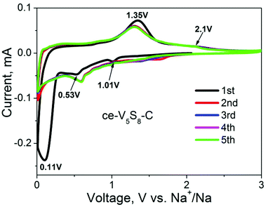 | ||
| Fig. 4 Cyclic voltammograms (CV) of ce-V5S8–C nanosheets as the anode materials for SIBs for the first five cycles at a scan rate of 0.1 mV s−1. | ||
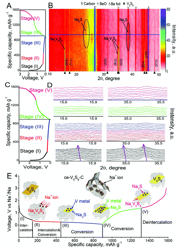
To support the above hypothesized potential-dependent sodiation/desodiation reaction mechanisms, in situ XRD was performed on a live SIB containing a ce-V5S8–C anode operated in a voltage window of 0.01–3.00 V; the diffraction patterns are shown in Fig. 5B and D. The corresponding desodiation/sodiation processes to each phase composition are color-marked in Fig. 5A–E. It needs to be pointed out that the peak at 45.2° is derived from the Be window; the peaks at 38.7°, 41.4° and 44.1° are derived from BeO and the peak at 26.5° corresponds to the carbon black paper. The peaks at 15.7°, 17.4°, 35.2°, 44.7° and 45.3° are from the active ce-V5S8–C anode, corresponding to the (002), (111), (222), (![[2 with combining macron]](https://www.rsc.org/images/entities/char_0032_0304.gif) 24) and (224) planes of the ce-V5S8 nanosheets, respectively. Based on the reaction sequence revealed in the CV curves in Fig. 4, we propose a 5-stage scheme in Fig. 5E to illustrate the structural evolution and reaction mechanisms undertaken in ce-V5S8–C containing SIBs.
24) and (224) planes of the ce-V5S8 nanosheets, respectively. Based on the reaction sequence revealed in the CV curves in Fig. 4, we propose a 5-stage scheme in Fig. 5E to illustrate the structural evolution and reaction mechanisms undertaken in ce-V5S8–C containing SIBs.
In stage (I) (1.5–0.4 V), the rapid decrease in potential corresponds well with the peak shifts towards the lower 2θ of the (002) and (222) planes of ce-V5S8 in Fig. 5B and D. These shifts can be explained by the lattice expansion of the V5S8 nanosheets due to Na+ intercalation. In stage (II) (0.4–0.25 V), the peaks located at 15.7° (002), 34.9° (![[4 with combining macron]](https://www.rsc.org/images/entities/char_0034_0304.gif) 02) and 35.2° (222) continue to shift towards lower 2θ, suggesting further lattice expansion of the ce-V5S8 nanosheets caused by more Na+ intercalation. Combined with the ex situ TEM results shown in Fig. S15 (ESI†), the observation of Na2S in the products suggests a partial concurrent conversion reaction taking place. In contrast, in stage (III) (0.25–0.01 V), no noticeable shifts in the diffraction peaks of the ce-V5S8 nanosheets can be observed, implying that lattice expansion, thus Na+ intercalation, has stopped. When it was fully discharged to 0.01 V, a new diffraction peak centered at 38.8° appeared. This new peak is identified to be associated with Na2S, a product of the Na+ conversion reaction. As the ce-V5S8–C anode was recharged to 1.5 V in stage (IV), the peak of Na2S gradually disappeared, suggesting dissociation of the conversion reaction product. When it was fully recharged to 3.0 V in stage (V), the (002) and (222) characteristic peaks of the V5S8 nanosheets reappeared again.
02) and 35.2° (222) continue to shift towards lower 2θ, suggesting further lattice expansion of the ce-V5S8 nanosheets caused by more Na+ intercalation. Combined with the ex situ TEM results shown in Fig. S15 (ESI†), the observation of Na2S in the products suggests a partial concurrent conversion reaction taking place. In contrast, in stage (III) (0.25–0.01 V), no noticeable shifts in the diffraction peaks of the ce-V5S8 nanosheets can be observed, implying that lattice expansion, thus Na+ intercalation, has stopped. When it was fully discharged to 0.01 V, a new diffraction peak centered at 38.8° appeared. This new peak is identified to be associated with Na2S, a product of the Na+ conversion reaction. As the ce-V5S8–C anode was recharged to 1.5 V in stage (IV), the peak of Na2S gradually disappeared, suggesting dissociation of the conversion reaction product. When it was fully recharged to 3.0 V in stage (V), the (002) and (222) characteristic peaks of the V5S8 nanosheets reappeared again.
To recap, the proposed five stages are: (I) the V5S8 intercalation reaction (1.5–0.4 V), (II) the combination of the intercalation and conversion reaction (0.4–0.25 V), and (III) the conversion reaction, which accounts for the conversion capacity (0.25–0.01 V). Conversely, stage (IV) and (V) correspond to the dissociation reaction of Na2S to Na+, V and NaxV5S8, and the deintercalation of NaxV5S8 to form V5S8 nanosheets, respectively. The (de)intercalation and conversion processes appear to be rather reversible, while their irreversible capacity losses mainly arise from the inactive V residue, S dissolution and SEI formation in the initial cycle. Combining electrochemical performance and the in situ XRD results, the Na+ storage mechanism in the ce-V5S8–C anode can be characterized by intercalation and conversion reactions as follows:
| Na+ intercalation: V5S8 + xNa+ + xe− → NaxV5S8 (>0.4 V) | (1) |
| Na+ intercalation: V5S8 + xNa+ + xe− → NaxV5S8 and partial Na+ conversion: NaxV5S8 + (16 − x)Na+ + (16 − x)e− → 8Na2S + 5V (0.4–0.25 V) | (2) |
| Full Na+ conversion: NaxV5S8 + (16 − x)Na+ + (16 − x)e− → 8Na2S + 5V (<0.25 V) | (3) |
| 8Na2S + 5V → NaxV5S8 + (16 − x)Na+ + (16 − x)e− (<1.35 V) | (4) |
| NaxV5S8 → V5S8 + xNa+ + xe− (>1.35 V) | (5) |
In summary, monoclinic structured ce-V5S8 and graphite hybrid nanosheets were fabricated using a chemical exfoliation method, and investigated as anode materials for SIBs. Electrochemical evaluations indicate that ce-V5S8–C is a better SIB anode than ce-V5S8 and ce-VS2, demonstrating a high reversible discharge capacity (682 mA h g−1 at 0.1 A g−1) and a reasonable cycle life (496 mA h g−1 at 1.0 A g−1 after 500 cycles). It particularly exhibits high rate capacities of 389 and 344 mA h g−1 at 5.0 and 10.0 A g−1, respectively. This good performance is mainly attributed to the unique three-dimensional monoclinic structure of V5S8, which facilitates electronic/ionic diffusion and conversion reactions, as well as graphite. The in situ XRD study revealed that the high capacity of ce-V5S8–C originates from a combined Na+ intercalation and conversion reaction. Overall, this work demonstrates that the ce-V5S8–C hybrid is a promising anode material for SIBs.
Acknowledgements
We gratefully acknowledge the financial support from the Natural Science Foundation of China (51402109), the Project of Public Interest Research and Capacity Building of Guangdong Province (2014A010106007), the Pearl River S&T Nova Program of Guangzhou (201506010030), the Guangdong Innovative and Entrepreneurial Research Team Program (No. 2014ZT05N200) and the Guangdong Natural Science Funds for Distinguished Young Scholar (No. 2016A030306010).Notes and references
- L. Croguennec and M. R. Palacin, J. Am. Chem. Soc., 2015, 137, 3140 CrossRef CAS PubMed.
- D. Larcher and J. Tarascon, Nat. Chem., 2015, 7, 19 CrossRef CAS PubMed.
- D. Kundu, E. Talaie, V. Duffort and L. F. Nazar, Angew. Chem., Int. Ed., 2015, 54, 3431 CrossRef CAS PubMed.
- M. H. Han, E. Gonzalo, G. Singh and T. Rojo, Energy Environ. Sci., 2015, 8, 81 CAS.
- D. Liu, Z. Yang, W. Li, S. Qiu and Y. Luo, Electrochim. Acta, 2010, 55, 1013 CrossRef.
- K. Nobuhara, H. Nakayama, M. Nose, S. Nakanishi and H. Iba, J. Power Sources, 2013, 243, 585 CrossRef CAS.
- S. Komaba, W. Murata, T. Ishikawa, N. Yabuuchi, T. Ozeki, T. Nakayama, A. Ogata, K. Gotoh and K. Fujiwara, Adv. Funct. Mater., 2011, 21, 3859 CrossRef CAS.
- Z. H. Wang, L. Qie, L. X. Yuan, W. X. Zhang, X. L. Hu and Y. H. Huang, Carbon, 2013, 55, 328 CrossRef CAS.
- Y. Cao, L. Xiao, M. L. Sushko, W. Wang, B. Schwenzer, J. Xiao, Z. Nie, L. V. Saraf, Z. Yang and J. Liu, Nano Lett., 2012, 12, 3783 CrossRef CAS PubMed.
- K. Tang, L. Fu, R. J. White, L. Yu, M. M. Titirici, M. Antonietti and J. Maier, Adv. Energy Mater., 2012, 2, 873 CrossRef CAS.
- L. Wu, X. H. Hu, J. F. Qian, F. Pei, F. Y. Wu, R. J. Mao, X. P. Ai, H. X. Yang and Y. L. Cao, Energy Environ. Sci., 2014, 7, 323 CAS.
- A. Darwiche, C. Marino, M. T. Sougrati, B. Fraisse, L. Stievano and L. Monconduit, J. Am. Chem. Soc., 2012, 134, 20805 CrossRef CAS PubMed.
- B. Farbod, K. Cui, W. P. Kalisvaart, M. Kupsta, B. Zahiri, A. Kohandehghan, E. M. Lotfabad, Z. Li, E. J. Luber and D. Mitlin, ACS Nano, 2014, 8, 4415 CrossRef CAS PubMed.
- L. Xiao, Y. Cao, J. Xiao, W. Wang, L. Kovarik, Z. Nie and J. Liu, Chem. Commun., 2012, 48, 3321 RSC.
- M. Gu, A. Kushima, Y. Y. Shao, J. G. Zhang, J. Liu, N. D. Browning, J. Li and C. M. Wang, Nano Lett., 2013, 13, 5203 CrossRef CAS PubMed.
- H. Xiong, M. D. Slater, M. Balasubramanian, C. S. Johnson and T. Rajh, J. Phys. Chem. Lett., 2011, 2, 2560 CrossRef CAS.
- Z. Hu, L. X. Wang, K. Zhang, J. B. Wang, F. Y. Cheng, Z. L. Tao and J. Chen, Angew. Chem., Int. Ed., 2014, 126, 13008 CrossRef.
- J. Y. Liao and A. Manthiram, Nano Energy, 2015, 18, 20 CrossRef CAS.
- D. W. Su, S. X. Dou and G. X. Wang, Chem. Commun., 2014, 50, 4192 RSC.
- E. Yang, H. Ji and Y. Jung, J. Phys. Chem. C, 2015, 119, 26374 CAS.
- Y. Jing, Z. Zhou, C. R. Cabrera and Z. F. Chen, J. Phys. Chem. C, 2013, 117, 25409 CAS.
- W. Fang, H. Zhao, Y. Xie, J. Fang, J. Xu and Z. Chen, ACS Appl. Mater. Interfaces, 2015, 7, 13044 CAS.
- A. V. Murugan, M. Quintin, M. H. Delville, G. Campet and K. Vijayamohanan, J. Mater. Chem., 2005, 15, 902 RSC.
- X. Q. Xie, Z. M. Ao, D. W. Su, J. Q. Zhang and G. X. Wang, Adv. Funct. Mater., 2015, 25, 1393 CrossRef CAS.
- X. Q. Xie, T. Makaryan, M. Q. Zhao, K. L. V. Aken, Y. Gogotsi and G. X. Wang, Adv. Energy Mater., 2015, 6, 1502161 CrossRef.
- A. Fujimori, M. Saeki and H. Nozaki, Phys. Rev. B: Condens. Matter Mater. Phys., 1991, 44, 163 CrossRef CAS.
- M. Knechty, H. Eberty and W. Benschz, J. Phys.: Condens. Matter, 1998, 10, 9455 CrossRef.
- X. Y. Chen, X. Wang, Z. H. Wang, W. C. Yu and Y. T. Qian, Mater. Chem. Phys., 2004, 87, 327 CrossRef CAS.
- C. H. Yang, J. Lia, Y. Lin, J. Liu, F. L. Chen and M. L. Liu, Nano Energy, 2015, 11, 704 CrossRef CAS.
- V. Palomares, P. Serras, I. Villaluenga, K. B. Hueso, J. Carretero-González and T. Rojo, Energy Environ. Sci., 2012, 5, 5884 CAS.
- H. S. Hou, C. E. Banks, M. J. Jing, Y. Zhang and X. B. Ji, Adv. Mater., 2015, 27, 7895 CrossRef CAS.
- A. Ponrouch, A. R. Goñi, M. T. Sougrati, M. Ati, J. M. Tarascon, J. N. Avendaño and M. R. Palacín, Energy Environ. Sci., 2013, 6, 3363 CAS.
- S. Grugeon, S. Laruelle, R. H. Urbina, L. Dupont, P. Poizot and J. M. Tarascona, J. Electrochem. Soc., 2001, 148, A285 CrossRef CAS.
- Y. Zhu, L. Suo, T. Gao, X. Fan, F. Han and C. Wang, Electrochem. Commun., 2015, 54, 18 CrossRef CAS.
- Y. Liu, H. Wang, L. Cheng, N. Han, F. Zhao, P. Li, C. Jin and Y. Li, Nano Energy, 2016, 20, 168 CrossRef CAS.
- X. Ou, X. H. Xiong, F. H. Zheng, C. H. Yang, Z. H. Lin, R. Z. Hu, C. Jin, Y. Chen and M. L. Liu, J. Power Sources, 2016, 325, 410 CrossRef CAS.
- S. H. Choi and Y. C. Kang, Nanoscale, 2015, 7, 3965 RSC.
- T. Wang, P. Hu, C. Zhang, H. Du, Z. Zhang, X. Wang, S. Chen, J. Xiong and G. Cui, ACS Appl. Mater. Interfaces, 2016, 8, 7811 CAS.
- Y. X. Wang, S. L. Chou, D. Wexler, H. K. Liu and S. X. Dou, Chem. – Eur. J., 2014, 20, 9607 CrossRef CAS PubMed.
- S. H. Choi, Y. N. Ko, J.-K. Lee and Y. C. Kang, Adv. Funct. Mater., 2015, 25, 1780 CrossRef CAS.
- R. Sun, Q. Wei, Q. Li, W. Luo, Q. An, J. Sheng, D. Wang, W. Chen and L. Mai, ACS Appl. Mater. Interfaces, 2015, 7, 20902 CAS.
- D. Su, K. Kretschmer and G. Wang, Adv. Energy Mater., 2016, 6, 1501785 CrossRef.
- S. Yuan, S. Wang, L. Li, Y. H. Zhu, X.-B. Zhangand and J.-M. Yan, ACS Appl. Mater. Interfaces, 2016, 8, 9178 CAS.
- C. Wu, Y. Jiang, P. Kopold, P. A. V. Aken, J. Maier and Y. Yu, Adv. Mater., 2016, 28, 7276 CrossRef CAS PubMed.
- S. H. Choi and Y. C. Kang, Nanoscale, 2016, 8, 4209 RSC.
- K. Share, J. Lewis, L. Oakes, R. E. Carter, A. P. Cohn and C. L. Pint, RSC Adv., 2015, 5, 101262 RSC.
- G. D. Park and Y. C. Kang, Chem. – Eur. J., 2016, 22, 4140 CrossRef CAS PubMed.
- J. S. Cho, S. Y. Lee and Y. C. Kang, Sci. Rep., 2016, 6, 23338 CrossRef CAS PubMed.
- M. Krengel, P. Adelhelm, F. Kleinc and W. Bensch, Chem. Commun., 2015, 51, 13500 RSC.
- X. Liu, K. Zhang, K. Lei, F. Li, Z. Tao and J. Chen, Nano Res., 2016, 9, 198 CrossRef CAS.
- K. Zhang, M. Park, L. M. Zhou, G. H. Lee, W. J. Li, Y. M. Kang and J. Chen, Adv. Funct. Mater., 2016, 26, 6728 CrossRef CAS.
Footnote |
| † Electronic supplementary information (ESI) available: Detailed experimental procedures, additional XRD, SEM, and sodium storage performance of ce-V5S8, ce-V5S8–C and ce-VS2 nanosheets. See DOI: 10.1039/c6ee03173k |
| This journal is © The Royal Society of Chemistry 2017 |

