 Open Access Article
Creative Commons Attribution 3.0 Unported Licence
Multi-step continuous-flow synthesis
Joshua
Britton†
* and
Colin L.
Raston
 *
*
School of Chemical and Physical Sciences, Flinders University, Bedford Park, South Australia 5042, Australia. E-mail: Colin.raston@flinders.edu.au
First published on 20th January 2017
Abstract
Organic chemistry is continually evolving to improve the syntheses of value added and bioactive compounds. Through this progression, a concomitant advancement in laboratory technology has occurred. Many researchers now choose to mediate transformations in continuous-flow systems given the many benefits over round bottom flasks. Furthermore, reaction scale up is often less problematic as this is addressed at the inception of the science. Although single-step transformations in continuous-flow systems are common, multi-step transformations are more valuable. In these systems, molecular complexity is accrued through sequential transformations to a mobile scaffold, much like an in vitro version of Nature's polyketide synthases. Utilizing this methodology, multi-step continuous-flow systems have improved the syntheses of active pharmaceutical ingredients (APIs), natural products, and commodity chemicals. This Review details these advancements while highlighting the rapid progress, benefits, and diversification of this expanding field.
Key learning points(1) Continuous-flow synthesis aids multi-step transformations by providing efficient mixing and thermal control.(2) Continuous-flow chemistry allows reaction and reagent confinement during multi-step transformations. (3) In-line purification of intermediate compounds is vital to increase reaction yields and efficiencies. (4) In-line spectroscopy allows detection of intermediate compounds to ensure maximal yields are maintained. (5) Active Pharmaceutical Ingredients (APIs), natural products and commodity chemicals have benefited from continuous-flow syntheses. |
Organic chemistry continually evolves to develop novel approaches to the construction of active pharmaceutical ingredients (APIs), value added compounds, and vital materials. For hundreds of years chemists have addressed these challenges by performing reactions in round bottom flasks; an approach often suitable for a plethora of syntheses. However, with a significant advancement in laboratory technology, chemistry has the opportunity to become more efficient, safer, and automated. Translating reactions into continuous-flow systems is aiding researchers in pursuit this vision.
Continuous flow chemistry continues to thrive in academic and industrial laboratories fuelled by efficient and innovative syntheses. As a result, this discipline has diversified and expanded to provide novel, and practical solutions to organic chemistry, biochemistry,1,2 renewable fuels3,4 and materials synthesis.5 Mediating transformations in continuous-flow systems offers several advantages compared to the same reaction in a round bottom flask. The ability of continuous-flow systems to rapidly heat and cool reactions,6 micromix solutions,7 and improve reaction homogeneity affords opportunities to explore novel transformations while being environmentally conscious and creative.8 In addition, continuous-flow systems incorporate reaction scale-out at the inception of the science, allowing for effective on-demand compound generation in compact, reconfigurable devices.9 In this context, ‘scaling-out’, or ‘numbering up’ refers to an array of continuous-flow systems operated in parallel to meet the required output.10 For example, imagine that A and B react to give C. In a parallel array, both reagents A and B would be fed into several continuous-flow devices, and the product C channeled into a central collection. If the required output was 5 L h−1, and each reactor had a capacity of 0.5 L h−1, then it would require an array of ten reactors to meet the demand.
Although several commercially available systems can mediate continuous-flow transformations, many laboratories construct their own equipment from affordable and readily available parts. Furthermore, plans for continuous-flow devices can be downloaded and printed within hours using a fused-deposition modeling-type printer,11 expanding opportunities for researchers curious about the benefits of continuous flow. However, organic solvents are often not compatible with the materials used in the fabrication of these devices. Thus, when considering material choice, care must be taken. For those new to the field, PFA tubing is a more suitable starting point (vide infra).
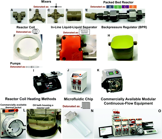
At the core of continuous-flow systems are pumps that drive fluids through channels, tubes, or packed beds in a continuous fashion (Fig. 1). Multi-step continuous-flow platforms are essentially several reactors connected into a single flow sequence. To draw a comparison, reactor coils are analogous to round bottom flasks in that they mediate chemical transformation. The injected fluid flows into reactor coils where the specific transformation is subjected to a range of conditions. For example, the fluid entering the reactor coil can be rapidly heated or cooled to mediate an effective transformation. Typically, reactor coils are constructed from PFA or stainless steel, but can be constructed from catalytically active metals such as copper (Fig. 1F). Here, the internal diameter and length of the reactor coil dictates the residence time of the fluid within the system. Mixers and unions connect reactor coils together, and allow the addition of new reagents to the continuous-flow stream. The solution can be flowed through packed bed reactors to ensure efficient mixing, or to provide exposure to immobilized reagents for synthetic transformations (Fig. 1E). Furthermore, in-line separation of immiscible fluids (e.g. toluene and water) is possible through the use of membrane-based liquid–liquid separators (Fig. 1G). In these separators, the organic component passes through a membrane into a new continuous-flow stream. In-line liquid–liquid separators have been highly utilized, and are discussed below. Finally, the continuous-flow system is normally operated under a level of backpressure, controlled by a backpressure regulator (Fig. 1H). Subjecting the continuous-flow stream to a backpressure allows solvents to be used above their atmospheric boiling points while ensuring reaction homogeneity as the solution passes between reactor coils at different temperatures. Such a large toolbox of continuous-flow equipment leads to reaction diversity and flexibility, allowing demanding chemical challenges to be met.
A multi-step continuous-flow reaction is when more than one transformation occurs to a mobile motif in a single sequence. In this respect, reaction telescoping could also be an adequate description. However, unlike reaction telescoping (multiple transformations without purification of intermediates) in round bottom flasks, continuous-flow systems allow the possibility of in-line purification and reagent introduction at set points in the continuous-flow sequence. Furthermore, plug flow conditions and reaction compartmentalization can be utilized to drive higher reaction efficiencies. Plug flow describes a certain type of fluid movement through the reactor. In plug-flow regime, the fluid moves through the reactor in thin uniform plugs. It is assumed that there is perfect mixing in the vertical direction, but none in the horizontal. To this avail, reactions are compartmentalized to each plug of fluid moving through the reactor. This means that chemical species have limited diffusion from one plug to another.
This Review focuses on multi-step continuous-flow reactions from 2009 onwards. Prior to 2009, an excellent Review exists,12 as do several discussion on the benefits of flow chemistry.12,13 The transformations described herein have been simplified for clarity and consistency. The synthesis of, and towards, 22 APIs are detailed, as well as numerous other transformations including the synthesis of intermediates en route to natural products.
1. Functional group transformations
This section examines multi-step continuous-flow functional group transformations. In each of the examples, the benefits of mediating the reaction in continuous-flow have been highlighted. The purpose of this section is to provide a source of inspiration for future transformations while exploring the benefits of continuous-flow systems over round bottom flasks.1.1 Amides
Amides are fundamentally important molecules due to their vast biological occurrence and synthetic versatility. In this respect, an expedited synthesis of these molecules could have broad significance in medicinal and biochemical studies. First, the Djuric group recently developed a reaction–deprotection–reaction strategy to afford asymmetric amides (Fig. 2A).14 Here, the first reactor coil mediates acylation between a wide variety of amines and acyl chlorides. This solution then exits into a second reactor coil where thermal BOC-deprotection affords the free amine. The ability to rapidly heat from room temperature to 300 °C highlights a major benefit of continuous flow. In batch, it would be extremely difficult to perform rapid thermal changes in short order, with the likelihood of unwanted byproducts also increasing. Furthermore, as CO2 is produced as a byproduct, it would pose a safety concern in large batch reactions. In continuous-flow however, gas release can be managed. The deprotected moiety is then subjected to sequential acylation to generate unsymmetrical amides. To note is the high temperature of the second coil, and the large backpressure required. The Phoenix reactor was specifically chosen due to its ability to safety mediate the three-step, eight-minute process under such harsh conditions. Overall, a range of structurally diverse products was synthesized in yields exceeding 99%. This simple continuous-flow system has added a useful tool to the medicinal chemistry toolbox.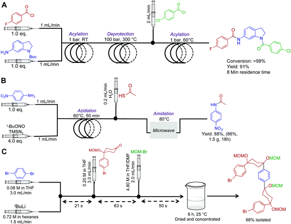 | ||
| Fig. 2 Continuous-flow synthesis of amides, and a semi-continuous flow synthesis of a U-shaped compound used in the synthesis of [10]CPP. (A) A three-step synthesis to asymmetric amides.14 (B) A three-step process converting aniline derivatives to secondary amides via the azide, at 83 mg h−1.15 (C) 1,4-Dibromobenzene is fed into the reaction sequence at 3.0 mL min−1 along with tBuLi at 1.5 mL min−1 in a separate channel. This affords mono-lithium species over 21 s which then undergoes nucleophilic addition with the introduced ketone over 63 s. MOM-Br is then introduced to protect the newly formed secondary alcohol with the exiting product stirred in a vial for six hours before isolation.16 | ||
Next, a microwave assisted continuous-flow reactor generated secondary amides from aniline derivatives through in situ azide generation (Fig. 2B). In this sequence, a heated reactor coil first mediates azidanation with tert-butyl nitrite. This example highlights a major benefit of continuous-flow systems; the ability to handle hazardous species in a safe manner. In batch reactors, the handling of azides or other unstable species can be problematic due to explosion concerns. In continuous flow, the azide is generated in a small volume reactor coil before immediate consumption in a sequential step. This ensures only small concentrations of the azide are present at all times. However, safety should always be of prime importance when heating nitrogen rich compounds in both continuous-flow and batch reactors. When using hazardous species, a full safety review should be carried out and the appropriate measures taken to ensure a controlled reaction. This continuous-flow system generated the amide shown in Fig. 2B in 86% yield over 18 h.15
1.2 Materials chemistry compounds
Multi-step continuous-flow systems have recently featured in the synthesis of compounds for materials chemistry applications. The synthesis of [10]cycloparaphenylene ([10]CPP) for bottom up approaches to carbon nanotube synthesis was translated into continuous flow for rapid material generation (Fig. 2C).16 This example is known as flash-continuous-flow chemistry due to the incredibly rapid reaction rates. During optimization, nucleophilic addition of the lithium-aryl species required only three seconds. Furthermore, other transformations required only tens of seconds. Performing this transformation in continuous flow allowed lithium–halogen exchange at room temperature. In batch reactions, cryogenic temperatures (−78 °C for example) are often required to stop byproduct formation. Although this is a great example of a multi-step transformation, the last step was performed in a round bottom flask. Presumably, slow reaction rates were unsuitable for continuous flow approaches. Finally, when performing these rapid transformations, the fluid exiting the system should be effectively quenched to ensure accurate determination of the continuous flow transformation.1.3 Heterocycles
Continuous-flow chemistry has been used to generate libraries of heterocycles such as 5-(thiazol-2-yl)-4,4-dihydropyrimidin-2(1H)-one (DHPM) derivatives (Fig. 3A). In this sequence, two microfluidic chips are used to each mediate a specific transformation. Microfluidic chips are distinctly different to the reactor coils described above as they typical manipulate fluid in channels ranging ×10−6–×10−12 L. Their construction, maximum flow rates and volumes provide a flexible alternative to continuous-flow reactor coils. It is however possible to use a mixture of both reaction platforms as they often operate the same fittings. In this sequence, the first microfluidic chip generates the β-ketothiazole motif with concomitant removal of the 1,3-dioxane protecting group. The fluid then passes into the second microfluidic chip where a rapid Biginelli reaction affords DHPM derivatives in medium yields over a 13.75 min residence time.17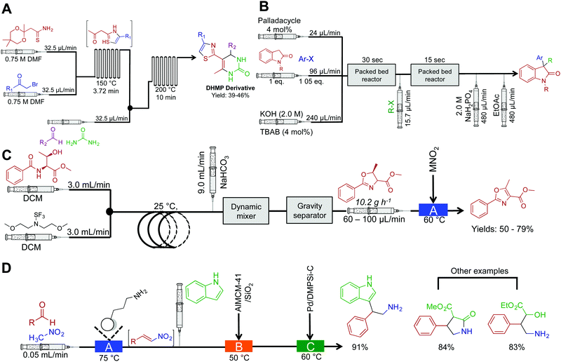 | ||
| Fig. 3 Continuous-flow synthesis of heterocycles. (A) The synthesis of DHMP derivatives using two serially linked microfluidic chips.17 (B) Continuous-flow synthesis of 3,3-disubstitutedoxindoles using two-serially linked packed bed reactors. TBAB (tetrabutylammonium bromide) and the packed bed reactors had 180 μL and 90 μL capacities respectively. Yields between 62–95%.18 (C) Two continuous-flow processes harnessing Deoco-Fluor, and activated MnO2, generate six oxazoles in good yield.19 (D) A three-step process generated nitrogen containing heterocycles in excellent yield.21 | ||
Substituted oxindoles comprise a large class of alkaloid natural products that often infer biological activity. The Buchwald group developed a two-step process that mediates palladium-catalyzed α-arylation of oxindoles with subsequent alkylation to generate 3,3-disubstitutes oxindoles (Fig. 3B). As the reaction was run biphasic, solutions were passed through a packed bed reactor to provide efficient mixing. This provides an example of another benefit of continuous flow; the ability to mediate biphasic reactions via micromixing apparatus. In round bottom flasks, the reaction typically occurs at the interface of the two solutions. Although this scenario is sometimes beneficial, it often leads to low reactivity rates due to inefficient mixing. This can be overcome in continuous flow by using plug flow conditions (the solutions appear as pellets traveling through the reactor) where more turbulent mixing occurs. Furthermore, as this example demonstrated, passing the solution through a packed bed reactor containing sand, stainless steel chippings, or glass beads will provide efficient mixing. This system generated 14 compounds in good to excellent yields (62–95%) in 58 s to 23 min residence time.18
The Ley group synthesized substituted oxazoles via a two-step process (Fig. 3C).19 This simple, and robust process was mediated by the Vapourtec R2/R4+ platform, a commercially available continuous-flow reactor. In the first reactor, β-hydroxy amides are converted to oxazolines with inversion of stereochemistry. After intermediate purification using gravity-based separation, the resulting solution is flowed through a packed bed reactor housing manganese dioxide to mediate oxidation to oxazoles in good yield. The ability to expose continuous-flow streams to solid reagents in a controlled and confined manner avoids problems associated with solid addition and catalyst removal. However, packed bed reactors have a finite lifetime; the supported reagent is consumed or poisoned over time. As described, purification from the complex mixture was achieved using a gravity-based separator. This type of separator is distinctly different to the Zaiput separators as shown in Fig. 1. Membrane separation allows a true continuous-flow process by passing the organic phase through a membrane and into a new stream. Gravity separation is mechanistically similar to a typical organic liquid–liquid separation used in batch chemistry. However, the incorporation of cameras allows automatic draining of the separator to form a semi-continuous purification process.20
A three-step continuous-flow sequence transformed aromatic aldehydes into nitrogen containing heterocycles using heterogeneous catalysis (Fig. 3D).21 In the first reactor, aldehydes are transformed into β-nitrostyrenes via the Henry (Nitro Aldol) reaction. Here nitromethane and the aldehyde of choice are passed through an amino-functionalized silica gel column to mediate Aldol addition and then elimination of water to yield nitroalkenes. The amino-functionalized column catalyzes the reaction and is constructed from commercially available silica resin (Aldrich, $5.21 USD g−1). Once again, care should be taken on the longevity of these columns; over time, decreased efficiency will occur through leaching, consumption, or poisoning. There is thus some debate on whether the use of immobilized reagents is truly continuous-flow; the column will have to be replaced over time. Finally, the nitroalkene motifs are transformed (via conjugate addition, for example) to generate a range of compounds. These compounds can further undergo reduction with palladium to access the free amine, providing opportunities to synthesize additional amides and tryptophan analogues.
1.4 Peptide related synthesis
The Kappe group developed a two-step system for the synthesis of peptoids in high yields with short residence times (Fig. 4). Peptoids are non-natural amino acid mimics that can have identical biological activity, but often with increased bioavailability. In the first reactor coil, an Ugi coupling generates a scaffold ready for sequential copper mediated azide–alkyne cycloaddition (CuAAC) which is achieved by passing the solution through a copper reactor coil to generate the triazole linker.22 This highlights two further benefits of continuous flow. First, passing the solution through a reactor coil constructed from the required catalysts can provide the necessary conditions for an effective transformation. This type of reactivity is both convenient, and in the case of copper, relatively inexpensive. Second, azides are highly energetic hazardous species. However, they can be safely generated in situ under continuous-flow conditions for immediate consumption in a sequential step. This versatile continuous-flow strategy allowed the changing of the molecules ‘y’ and ‘x’ components to access eight different compounds. This again provides an additional benefit over batch reactions; changing the reagents entering the continuous-flow system can generate a large library of compounds through parallel synthesis. This not only increases the versatility of continuous-flow chemistry, but also demonstrates generalizability and efficiency.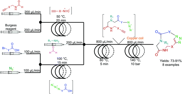 | ||
| Fig. 4 Continuous-flow synthesis of peptoides using a two-component multi-step reaction. A general example is detailed here with eight high yielding (73–91%) examples reported.22 | ||
The Ley group developed a two-step continuous-flow system for preparing natural and unnatural cyclooligomeric depsipeptides (Fig. 5).23 In this system, selective deprotection of O and N-protected amino acids, and subsequent coupling using Ghosez's reagent is achieved in the first reactor coil. In the second reactor coil, conversion of the dipeptides through cyclization yields the required peptoides. In this system, low reactor temperatures were required. Although The Polar Bear continuous-flow system maintained a reactor temperature of 0 °C, it is possible to place the reactor coil in a well-insulated ice bath, although, this is a less renewable approach. This process afforded greater yields than what is previously reported in batch systems, adding yet another example of improved yields in continuous flow (32–52%, Fig. 5).
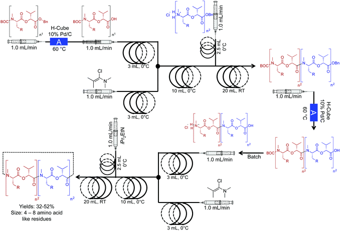 | ||
| Fig. 5 Continuous-flow synthesis of natural and unnatural cyclooligomeric depsipeptides using a two-component multi-step reaction. The Polar Bear Plus reactor is used in the lower temperature coupling (0 °C).23 Reactor A is the commercially available H-cube reactor. | ||
1.5 Cross-coupling reactions
The power of palladium cross coupling chemistry in continuous flow has been previously described,24 accordingly, this part of the Review details only recent examples.First, a three-step sequence for transforming aryl bromides to biaryls via Suzuki couplings was developed by Buchwald et al. (Fig. 6A). In the first reactor, lithium–halogen exchange occurs between an aryl bromide and nBuLi to afford the lithium salt in a rapid fashion (as quick as two seconds). This salt is then mixed with dilute B(OiPr)3 and passed through a second reactor coil to afford the borate. This transformation required only one minute at 60 °C, demonstrating that molecular complexity can be easily accrued in a rapid fashion in continuous-flow systems. In the final reactor coil, the borate is consumed in a Suzuki cross-coupling reaction to afford biaryls. In this system, probe sonication and dilute concentrations of B(OiPr)3 were required to quench the lithium–halogen exchange product. This technique avoided formation of an insoluble salt that would lead to reactor clogging. This raises a constant consideration in continuous flow; how can insoluble products be handled in small channels? As demonstrated in this example, one method is to run the reaction under dilute conditions so that solid formation can be easily managed. The second approach is for sonication to provide vibrations to move the solid through the tubing. Furthermore, vibrations can also increase solute solubility in avoiding insoluble material formation. In conclusion, this system created the core of API diflunisal, an important compound with analgesic and antipyretic effects.25
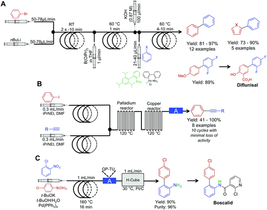 | ||
| Fig. 6 Continuous-flow synthesis for Suzuki and Sonogashira couplings. (A) A three-step reaction sequence yielded Suzuki products, with the precursor to diflunisal generated in 89% yield.25 (B) Two serially linked reactors catalyze Sonogashira reactions by harnessing the metal composition of the reactors for catalysis; the column labeled A in this sequence is a metal scavenging column.26 (C) Mediating a Suzuki reaction, followed by sequential reduction in the H-cube reactor, afforded the precursor to Boscalid in high yield and purity.27 The H-cube reactor used in this sequence was the X-cube flash reactor with a QP-TU (quadrapure thiourea) cartridge for scavenging Pd before reduction. | ||
Sonogashira chemistry was mediated by flowing solutions through sequential palladium and copper reactors (Fig. 6B).26 In the first reactor, oxidative addition between aryl iodides and palladium from the walls of the reactor occurs. The resulting solution then flows into the second (copper) reactor where the alkyne forms the cuprate. The two organometallic species then undergo transmetalation, then reductive elimination to form the aryl–alkyne motif in high yields in short order. This example further builds upon the copper reactor used for catalysis as described above.
The Kappe group developed a system for mediating cross-coupling reactions followed by sequential reduction in a commercially available H-cube reactor (Fig. 6C). This elegant process afforded the key precursor to the fungicide, Boscalid.27 In this multi-step sequence, 1-chloro-2-nitrobenzene is first coupled with 4-chlorophenylboronic acid with a 16 min residence time. The reaction mixture is then flowed through a commercially available quadrapure cartridge to remove excess palladium from the reaction stream before final reduction. Reduction in the H-cube reactor afforded 2-amino-4′-chloropheyl in high yield and purity (90 and 96% respectively). The H-cube reactor is an attractive alternative to performing reductions in round bottom flasks. This bench top apparatus safely generates hydrogen on demand through the electrolysis of water. Furthermore, there is no need to filter of the catalyst at the end of the reaction as the system operates immobilized metal cartridges. Finally, yields are often improved in continuous flow compared to the same reaction in batch.
1.6 Specific examples of multi-step transformations
In this section, cyclopropanation, hydroboration/oxidation of olefins, and homologation of esters are discussed. This section further highlights the rich diversity of continuous flow chemistry with some additional benefits over batch chemistry.Cyclopropane moieties exist in a wide range of biologically active molecules due to their ring conformation and constraints. In aiding their synthesis, nucleophilic diazo intermediates were synthesized, and consumed in a two-step, room temperature approach (Fig. 7A).28 First, activated MnO2 converts hydrazine derivatives to their corresponding diazo species. The choice of solvent and base in this transformation were crucial to afford a clean stream of product; in this case, the use of EtOAc and Hünigs base was optimal. After in situ diazo formation, the highly reactive species is immediately coupled to an olefin avoiding stockpiling of hazardous species. This process afforded 15 cyclopropane rings in good yield, and once more highlights the ability of continuous-flow systems to handle hazardous species. Explosion-prone diazo compounds are generated in situ, and then consumed via a sequential reaction. On-demand generation of hazardous species is appealing, but as described above, the appropriate safety measures should be taken when handling these potentially explosive compounds.
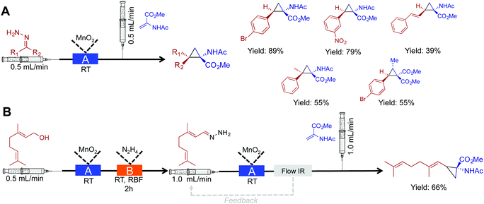 | ||
| Fig. 7 Continuous-flow synthesis of cyclopropane rings. (A) A two-step process converts hydrazine into cyclopropane rings via the diazo species.28 (B) Extending this to a three-step procedure allows the conversion of alcohols to cyclopropane rings. In both the schematics: Reactor A – column packed with manganese dioxide, and Reactor B – round bottom flask containing 1.05 eq. N2H4. | ||
Using this same method, a three-step sequence converted geraniol to the corresponding cyclopropane amino acid (Fig. 7B). In this system, geraniol is oxidized to the aldehyde before sequential, and safe transformation to the diazo species. The formation of the diazo species is monitored using in-line IR spectroscopy. Monitoring a peak at 2070 cm−1 ensured that the flow rate was low enough to provide optimal conversion to the diazo compound as it traveled through the packed bed reactor. The diazo compound is then immediately consumed to generate the cyclopropane amino acid in 66% yield.
Molecules containing hydroxyl functional groups find broad application and utility in the synthesis of natural products. A two-step sequence converted a range of olefins to alcohols through hydroboration and sequential oxidation (Fig. 8).29 β-Pinene was used as a model substrate with a BH3 complex in THF. After hydroboration in the first reactor, the intermediate is subjected to a stream of NaOH, H2O2, H2O, and EtOH to provide the alcohol in good yield in short residence times. A continuous reaction–extraction system removed the alcohol from the organic phase increasing the utility of this process further. This style of gravity separation has already been described above, and in this case, allowed decreased human intervention.
 | ||
| Fig. 8 Continuous-flow hydroboration and subsequent oxidation through a two-step process.29 In this example, 13 compounds were synthesized in good to excellent yields. | ||
Next, a Horner–Wadsworth–Emmons homologation of α,β-unsaturated esters was achieved through a dual reduction-olefination sequence (Fig. 9).30 This approach allowed a controlled partial reduction of esters to reveal aldehydes. In round bottom flasks, DIBAL-H is often avoided due to over reduction; it is more reliable to reduce the ester through to the alcohol, and then oxidize it to the aldehyde. Here, this problem was overcome in this continuous-flow system. Furthermore, the E-factor of the process was improved by avoiding excess chemistry to achieve the correct oxidation state. The resulting aldehyde undergoes Horner–Wadsworth–Emmons olefination to produce the elongated product in good to excellent yields.
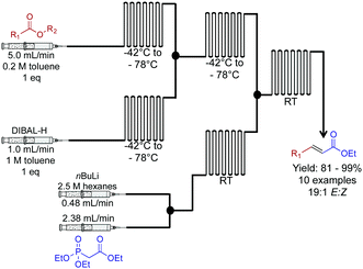 | ||
| Fig. 9 Continuous flow two-carbon extension of α,β-unsaturated esters using a Horner–Wadsworth–Emmons in a two-step continuous flow system.30 In this example, the use of DIBAL-H for a controlled reduction was achieved by use of a continuous-flow system. | ||
In a two-reactor coil sequence, the biaryl unit for the API atazanavir was synthesized in 74% yield (Fig. 10).32 This synthesis utilized both the power of membrane separation for in-line purification, and the H-cube reactor for reduction. In the first reaction coil, Suzuki cross coupling is performed at 150 °C. The solution then proceeds into the second reactor coil. To undergo Schiff-base formation, before entering the H-cube reactor for subsequent hydrogenation to afford the biaryl motif. In this sequence, it was crucial that membrane separation removed water-soluble impurities before reduction.
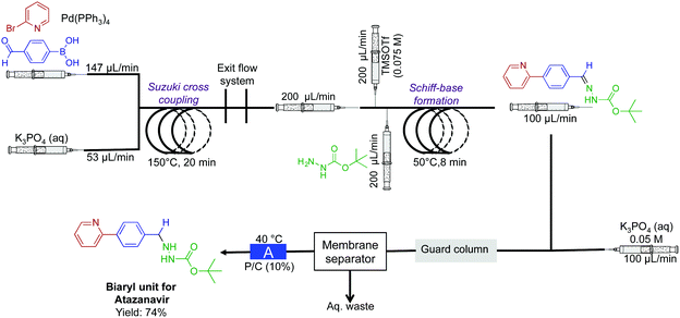 | ||
| Fig. 10 Continuous-flow synthesis of the biaryl unit for the API atazanavir. A three-step sequence afforded the bi-aryl motif in 75% yield.32 The reactor labeled A is the H-cube pro. | ||
Our laboratory has developed the synthesis of an α-aminophosphonate through an assembly line inspired approach. This thin-film approach uses a vortex fluidic device to generate an α-aminophosphonate in 80% yield in a ∼7 min residence time (Fig. 11).31 In this reaction sequence, all stages are performed in the most optimal solvent. Although this reaction can be performed as a three-component reaction, creating discrete species at set points in the reactor allowed enhanced reactivity. Processing in thin films allow facile solvent exchange under ambient conditions; imine synthesis is first mediated in methanol, followed by in situ solvent exchange with DMF, then addition of diethylphosphite.
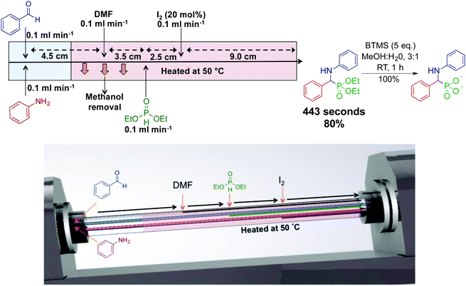 | ||
| Fig. 11 Continuous-flow synthesis of an α-aminophosphonate using dynamic thin films in an assembly line fashion.31 This assembly line inspired approach synthesized an α-aminophosphonate in 80% yield for a seven min residence time. Reproduced from ref. 31 with permission of Wiley, copyright 2017. | ||
Thin film continuous flow reactors are distinctly different to microfluidic chips and reactor coils. Thin films are generated through rapid rotation of a sample tube. Thin films have properties such as rapid heat and mass transfer, enhanced solvent evaporation rates, and the ability to confine a particular reaction to a set point in the reactor. The ability to switch solvents during reaction sequences allows each step of the reaction to be performed in their most ideal solvent.
The key intermediate for the synthesis of etodolac, a non-steroidal anti-inflammatory drug was synthesized in 100% conversion and 75% yield (Fig. 12).33 In this comparative study between batch and continuous flow, translating the reaction into a continuous-flow system increased yield, purity and conversion while decreasing byproducts formation. The ability to gain higher yields in continuous flow relates to the fundamental properties of the continuous-flow system. High heat and mass transfer coupled with micromixing and rapid temperature changes often provide superior yields compared to the same reaction in a round bottom flask. Furthermore, the high flow rates (230 mL min−1) used in this system are orders of magnitudes higher than that found in an academic setting.
 | ||
| Fig. 12 Continuous-flow synthesis of intermediate API 7-ethyltryptophol in the synthesis of etodolac. The three-step process produced 7-ethyltryptophol in 75% yield compared to only 45% in the batch process.33 | ||
The combination of continuous flow and batch chemistry can generate powerful routes to APIs. Vildagliptin, an oral antidiabetic drug, was synthesized through the generation, and subsequent reaction of the Vilsmeier reagent created in continuous flow, with that of an amide produced in batch (Fig. 13).34 Generating the hazardous Vilsmeier reagent in continuous flow improved the safety metrics of this reaction. The ability to reduce user interaction with hazardous intermediates highlights a benefits of this system. Overall, the reaction sequence generated the key intermediate for vildagliptin at 5.8 kg h L−1. A final substitution outside of the continuous-flow system afforded the API.
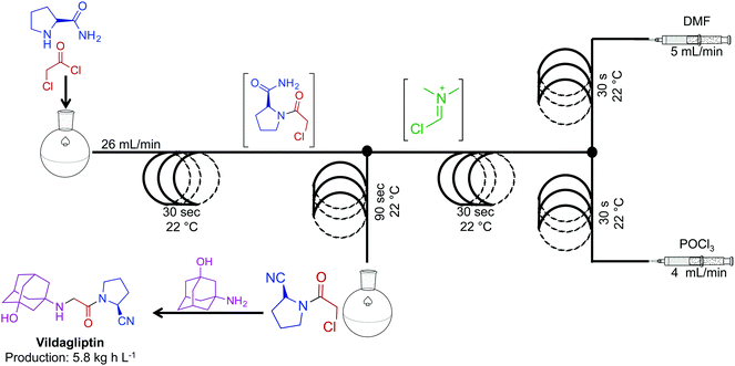 | ||
| Fig. 13 Continuous-flow synthesis of the intermediate for API vildagliptin. Combining two synthetic steps into a semi-continuous flow system produced the key intermediate for this API at 4.8 kg h L−1.34 | ||
2. Facilitating natural products synthesis
The synthesis of natural products often requires multiple complex transformations to generate the required target. Furthermore, chemists commit large amounts of time to generate enough material from prior steps, to perform delicate, later steps. In this respect, continuous flow could streamline natural product synthesis through on-demand generation of material for exploring final steps in complex syntheses. Such technology would allow chemists to concentrate on new reactivity by limiting the time spent on tedious transformations. Finally, continuous flow could expedite long syntheses into attractive, cohesive routes.Although the majority of continuous-flow syntheses focus on commodity chemical and API synthesis, there has been a significant advancement in the synthesis of more complex molecules. The Ley group have pioneered continuous-flow syntheses of natural products amongst other compounds.35 Arguably, the most complex continuous-flow synthesis to date was the generation of the key intermediates en route to the natural products spirangien A. Methyl ester and spirodienal A (Fig. 14 and 15).36 A semi-continuous-flow approach accessed a common homoallylic alcohol that is later transformed to a protected aldehyde or bis-alkyne. Through a series of linked reactor coils, microfluidic platforms, polymer supported reagents, and in situ analysis, a high yielding system requiring only minimal downstream processing was achieved.
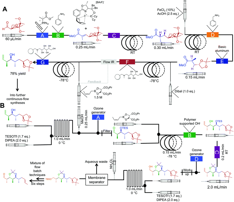 | ||
| Fig. 14 Semi multi-step continuous-flow synthesis towards key intermediates for the total synthesis of spirangien A methyl ester and spirodienal A. (A) A 2,3-butane diacetal protected aldehyde is transformed to the homoallylic alcohol. The lettered boxes detail a specific reactor condition; A – functionalized triphenylphosphine monolith for the Wittig reaction, B and D – quadrapure benzylamine, C – H2 at 20 bar for the asymmetric hydrogenation, E – basic alumina, F and G – IRA-743/silica. (B) Transformation of the homoallylic alcohol into the advanced aldehyde. A and D – ozone generation at 500 mL min−1, B – polymer supported hydroxide, C – quadrapure sulfonic acid.36 | ||
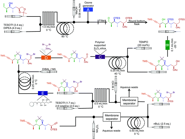 | ||
| Fig. 15 Semi multi-step continuous-flow synthesis towards the di-alkyne intermediate for the total synthesis of spirangien A methyl ester and spirodienal A. The homoallylic alcohol is transformed into the advanced dialkyne. The lettered boxes detail a specific reactor condition; A – an ozone generator producing 500 mL min−1 of O3 that is fed directly into a three-neck flask via a three-way valve, B – polymer supported hydroxide, C – polymer supports S2O3 silica, D – dibromo diphenylphosphine monolith for the Wittig reaction and E – IRA-743/silica.36 | ||
An important feature of this process was the use of in-line spectroscopy to monitor the concentration of incoming aldehyde for successful crotylation (Fig. 13A). Depending upon the concentration of the aldehyde in the feed stream, the flow rate of the crotylating reagent was adjusted to ensure optimal reactivity. Such in situ monitoring techniques allow for a level of control not possible in many batch type reactors. Using commercially available software, it is possible to link the in situ analysis back to the syringe pumps in order to control the flow rate of reagents, or solvents into the continuous-flow system. This level of automation is becoming increasingly common in continuous-flow systems. In conclusion, this system mediated 21 out of 25 transformations as a pioneering advancement in continuous-flow technology.
There is however a clear difference between many of the syntheses above, and the synthesis of these natural product intermediates. The molecules en route to these natural products often exit the continuous-flow system into a collection vial (depicted as a new pump in the scheme). The inherent complexity of these species, or technical issues (such as pump capability) could have limited the potential for a true continuous-flow process.
In 2010 the Holmes group reported a semi continuous-flow approach to the synthesis of perhydrohistrionicotoxin (Fig. 16).37 A mixture of reactor coils and microfluidic devices mediated seven transformations in continuous flow. Taking into account multi-step sequences, the natural product was synthesized in eleven steps, requiring only two chromatograph separations while avoiding aqueous work up steps (apart from the acetal hydrolysis, not shown). Furthermore, translating this sequence into continuous flow allowed organometallic reagents to be used at 0 °C, not the usual −78 °C. For example, Peterson Olefination gave comparable stereoselectivity at 0 °C in continuous flow; the high surface/volume ratio of the reagents contained within the reactor coils creates an environment for high heat, and mass transfer. This phenomenon provides new opportunities for avoiding cryogenic temperatures in reactions like those described above.
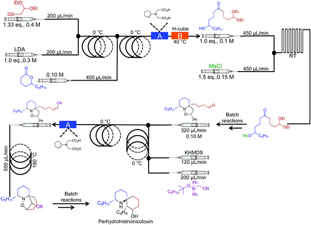 | ||
| Fig. 16 Semi continuous-flow synthesis of perhydrohistrionicotoxin. In this example, seven out of the eleven steps were mediated in continuous flow.37 | ||
3. Active pharmaceutical ingredients (APIs)
Active pharmaceutical ingredients often have an inherent complexity associated with their molecular framework. In this respect, translating their syntheses into continuous-flow reactors often requires advances in purification technology and new synthetic routes. Although more challenging than commodity chemical synthesis, several exciting advancements have occurred over the last five years. The synthesis of ibuprofen in 2009 by McQuade provides a starting point for this section (Fig. 17A).38 Here, three challenging transformations were incorporated into a single flow system to yield ibuprofen in 68% crude yield, or 51% following recrystallization. Five years later (2015), the Jamison group improved this synthesis by the removal of triflic acid to afford a more economical oxidative rearrangment.39 In their synthesis, ibuprofen required only three minutes residence time and yielded 83% at 8.09 g h−1 (>98% purity by 1H NMR, Fig. 17B). To note is the short residence times required, and that the reactor coils are constructed from affordable components. This provides an economically attractive alternative to expensive commercially available continuous-flow reactors.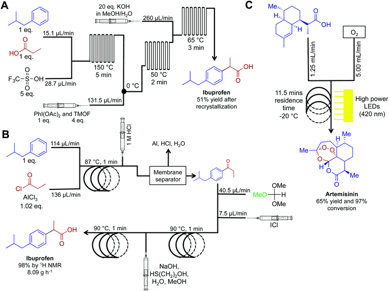 | ||
| Fig. 17 Continuous-flow syntheses of ibuprofen and artemisinin. (A) Ibuprofen is synthesized by Friedel–Crafts acylation followed by a 1,2-aryl migration, and finally ester hydrolysis.38 (B) This improved synthesis of ibuprofen used a membrane separator for in-line work-up while avoiding the need for triflic acid. This increased the yield to 98% with an overall reactor throughput of 8.09 g h−1.39 (C) Photochemical ene reaction using singlet oxygen as the key step preparing artemisinin at 8.33 g h−1.40,41 | ||
API synthesis in continuous flow often requires using several techniques to achieve high yields and purity before subsequent steps. In-line removal of soluble metal salts was achieved by passing the continuous-flow stream through a Zaiput membrane separator. After separation, the key intermediate resided in the organic phase, ready for subsequent transformations. These membrane separators have been discussed above, but it is noteworthy that these separators are very easy to operate, which is ideal for first time users.
Artemisinin is a key API in a range of antimalarial treatments. The synthesis of this molecule was translated into continuous flow for reaction scale up and on demand compound generation (Fig. 17C).40,41 The complexity of this molecule meant that there was no commercially viable routes to scale up. Translating this reaction sequence into continuous-flow allowed for an efficient and safe generation of singlet oxygen. Singlet oxygen is key in the transformation of dihydroartemisinic acid to artemisinin via a photochemical ene reaction. This efficient transformation was achieved by using 60 high-powered LEDs to create a high photon flux (420 nm, 72 W). This is another important example of the beneficial qualities of continuous flow. First, singlet oxygen is incredibly reactive. Thus, its generation, and immediate consumption in continuous flow provides increased safety compared to the round bottom flask. Second, and just as important, the high surface: volume ratio of fluid traveling through the flow system allowed even light penetration to the reagents.40 Performing photochemistry in round bottom flasks, or even larger batch reactors, is plagued by the inability of light to penetrate past the upper surface of the fluid. Mediating transformation in continuous-flow systems (where the thickness of the fluid is minimal) provides greater reaction homogeneity, efficiency, and yield. This system generated artemisinin at 8.33 g h−1, providing a viable scale up route to this important medicine.
The synthesis of (R)- and (S)-rolipram,42 aliskiren,43 rufinamide,44 and (E/Z)-tamoxifen35 have also been effectively translated into continuous-flow systems (Fig. 18 and 19). First, both enantiomers of rolipram were generated using a system comprised of four packed columns, each containing a specific heterogeneous catalyst. Flowing simple starting materials through the system afforded rolipram in 50% yield and in high enantiomeric excess (>99%) at 42 mg h−1 (Fig. 18). Impressively, the opposite enantiomer of rolipram was also accessible by simply switching the second packed column in the sequence (polymer supported-PYBOX-CaCl2) to a column containing the opposite enantiomer catalyst. This simple system alteration afforded rolipram in similar yield and high enantiomeric excess. The ability to switch modules of a continuous-flow system can provide access to a wide breadth of chemical space in short order compared to the same reactions in round bottom flasks.
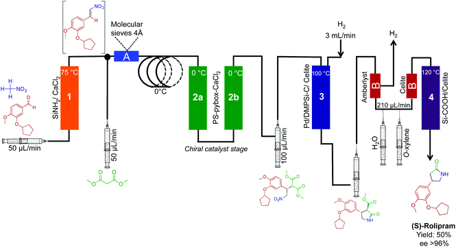 | ||
| Fig. 18 Continuous-flow synthesis of rolipram. Both enantiomers of rolipram were synthesized by simply switching the enantiomer of heterogeneous catalysts used.42 | ||
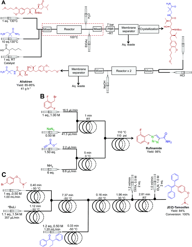 | ||
| Fig. 19 Continuous-flow synthesis of aliskiren, rufinamide and (E/Z)-tamoxifen. (A) The synthesis of aliskiren combines two synthetic steps to produce the final API in high yield at a nominal rate of 41 g h−1.43 Only the synthesis of the API is described in the figure above. In the earlier publication, many downstream processes afford the API in a formulated manner.45 (B) A three-step sequence generated rufinamide at 217 mg h−1.44 (C) A four-step system generated (E/Z)-tamoxifen at 9.35 g h−1.35 | ||
Popular renin inhibitor aliskiren hemifumarate was synthesized through a true end-to-end process (Fig. 19A). This continuous-flow system is one of the highlights from the literature with the synthesis, separation, purification, crystallization, drying and formulation being achieved in a single continuous-flow process.43,45 Here, acid catalyzed lactone ring opening generated the intermediate that is next isolated in the organic phase using a membrane separator. Clever in-line pH analysis controlled the flow rate of HCl into the stream to efficiently mediate BOC deprotection. This truly novel process afforded aliskiren hemifumarate at a maximum and nominal rate of 100 g h−1 and 41 g h−1 respectively. This was the first example of liquid reagents being converted to formulated medicines in a continuous fashion. Ultimately, it provided a new benchmark for continuous flow API synthesis.
The antiseazure medicine rufinamide was synthesized in eleven minutes using three reactor coils to mediate sequential transformations (Fig. 19B).44 Once again, copper tubing catalyzed the azide–alkyne cycloaddition to generate the 1,2,3-trizaole ring core of rufinamide. This appears to be the first API synthesis to utilize the reactor tubing in this manner, with the reaction sequence affording 217 mg h−1 of rufinamide, in 98% yield.
Ley et al. translated four sequential transformations into a continuous-flow system to generate (E/Z)-tamoxifen, an antibreast cancer drug in 100% conversion and 84% yield (Fig. 19C).35 This sequence utilized seven reactor coils to generate 9.35 g h−1 of this vital medicine. The diverse temperature gradients of this system are noteworthy, with one reactor coil mediating a reaction at −50 °C, and the next reaction at 30 °C. It would be hard to achieve such rapid thermal fluctuations in a round bottom flask over the same time. Attempts to perform the same rapid temperature changes in batch reactors would likely lead to byproduct formation and decreased yields.
The combination of novel reactivity and continuous-flow synthesis established a three-step route to efavirenz, an essential medicine for the treatment of HIV (Fig. 20).46 The previous routes to efavirenz required up to five steps (Merck and Lonza's routes), demonstrating that continuous flow improved both the efficiency of the synthesis with the possibility of reaction scale-out. In this continuous-flow system, a novel Ullman cyclization produced efavirenz in 45% yield with a residence time of <2 h. A silica-scavenging column removed byproducts from the continuous-flow stream to provide a method of in-line purification, but as with other columns, there is a finite lifetime. In these situations, in-line liquid–liquid separation would be attractive, if possible.
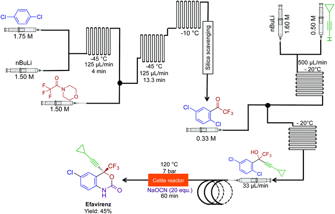 | ||
| Fig. 20 Continuous-flow synthesis of efavirenz. A three-step sequence produced efavirenz in 45% yield. The final step generated the carbomate ring. This is the shortest synthesis to efavirenz thus far.46 | ||
In acknowledging that the majority of APIs are synthesized through large-scale batch techniques, the Seeberger laboratory developed a non-iterative, five-stage assembly line sequence for the synthesis of numerous APIs (Fig. 21).47 Here, reactors can be interchanged to access a large breadth of chemical space. The first level of complexity affords the core of the API, and by changing the starting material entering the system, different APIs can be accessed with the same core. Sequentially passing the core through a series of sequential modules transforms the motif to generate β-amino acids, γ-amino acids and γ-lactones in good yields. Furthermore, switching modules determines whether γ-amino acids or γ-lactones are produced. The ability to generate large libraries of compounds through a modular continuous-flow platform is beneficial. If automated, this system could create a large range of structural analogues without being halted; the stream would be diverted into the required module to perform the required transformation. This sequence afforded pregabalin, gabapentin, phenibut, baclofen and rolipram in good yields (49–75%).
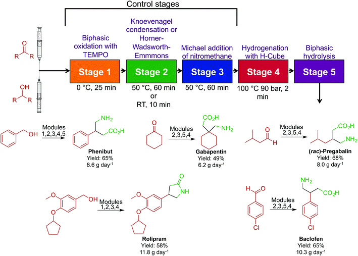 | ||
| Fig. 21 Continuous-flow synthesis of phenibut, gabapentin, pregabalin, rolipram and baclofen. A five-step reactor sequence allows for chemical space to be explored efficiently and rapidly, and changing the order of the reactors allowed access to different molecules.47 | ||
The antiemetic, and antihistamine compounds cyclizine, meclizine, cinnarizine and a buclizine derivative were synthesized through transformation of alcohols to their respective chlorides before successive reactions with piperazine (Fig. 22).48 Once again, membrane separators removed aqueous byproducts before sequential transformations, driving higher reaction efficiencies. This system generated cinnarizine at 2.0 mmol h−1 in good yield (82% recrystallized) as well as high yields of maclizine, cyclizine and buclizine. The authors noted that the development of HCl gas delivery into continuous-flow systems could revolutionize this methodology. However, using HCl gas makes this process troublesome; many continuous-flow platforms would likely corrode. It should be noted that gas delivery into continuous-flow systems is possible through the use of a mass-flow controller. This allows the safe and controlled delivery of gases into conventional continuous-flow equipment with ease. If attempted, safety should be prioritized when operating pressurized toxic and explosive gases.
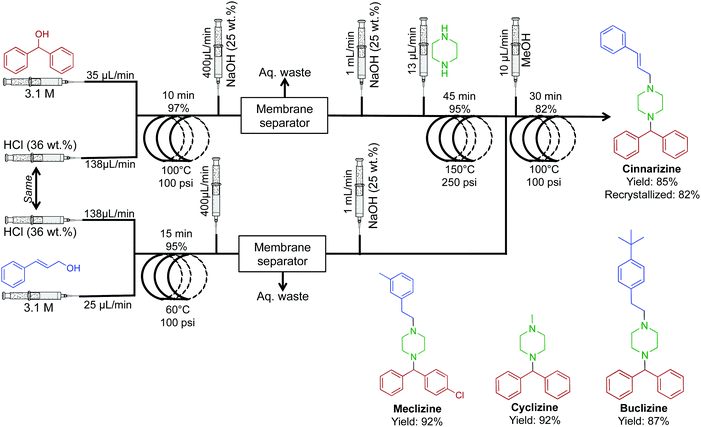 | ||
| Fig. 22 Continuous-flow synthesis of cinnarizine, maclizine, cyclizine and buclizine. Four transformations convert the respective alcohols into APIs in good yields.48 | ||
The synthesis of N,N-diethyl-4-(3-fluorophenylpiperidin-4-ylidenemethyl)benzamide, a potent and selective δ-opioid receptor was synthesized in a four-step sequence in 35% yield (Fig. 23).49 This sequence is superior to the previous five-step sequence that afforded the compound in only 9% yield. When compiled into a single system, intermediate dehydration using the Burgess Reagent limited the process. This was overcome using a controlled release of the Burgess Reagent by in situ IR-detection of the concentration of incoming substrate. This once again amplifies the importance of in situ analysis in continuous-flow systems.
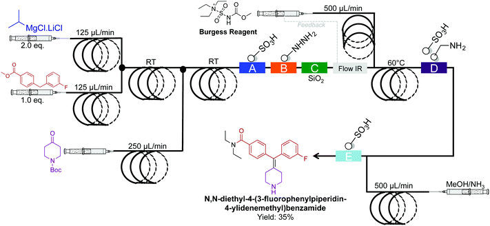 | ||
| Fig. 23 Continuous-flow synthesis of N,N-diethyl-4-(3-fluorophenylpiperidin-4-ylidenemethyl)benzamide. The four-step sequence generated the target API in35% yield.49 | ||
A high temperature and pressure synthesis of imidazoles was developed for aiding in the synthesis of daclatasvir, a NS5A inhibitor.50 Here α-halo ketones, N-protected L-proline and ammonium acetate afforded imidazoles without proceeding through ketoamide intermidiates (Fig. 24). Short residence times of 4–10 min generated the daclatasvir like scaffold in 81% yield. This strategy was also general for a range of starting materials, and synthesized 13 other imidazoles in good yields. The use of several immobilized reagents provided an efficient single flow process, and once again, these reagents are commercially available.
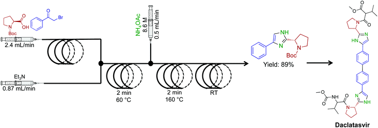 | ||
| Fig. 24 Continuous-flow synthesis of an imidazole fragment en route to the synthesis of Daclatasvir.50 | ||
Our laboratory has achieved a two-step synthesis of lidocaine in 85% yield using a dynamic thin film continuous-flow reactor (Fig. 25).51 Using an assembly line inspired approach allowed both transformations to occur in a single reactor. One of the benefits of using thin films in continuous flow is reactor compartmentalization. Much like in traditional continuous-flow chemistry where reagents can be injected at specific points, dynamic thin films have feed jets that deliver reagents at set points in the reactor. In a single pass in the vortex fluidic device, lidocaine is synthesized via incorporating amide bond formation, in situ solvent exchange and final SN2 substitution to afford lidocaine in 15%.
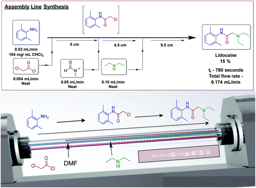 | ||
| Fig. 25 Continuous-flow synthesis of lidocaine using an assembly line inspired process contained within dynamic thin films using a vortex fluidic device.50 Reproduced from ref. 50 with permission of Wiley, copyright 2017. | ||
Finally, a collaborative effort at the Novartis-MIT center for continuous-flow processing produced a reconfigurable continuous-flow system for on demand production of diphenhydramine hydrochloride, lidocaine hydrochloride, diazepam and fluoxetine hydrochloride, in a rapid and compact system to meet U.S. Pharmacopeia standards (Fig. 26).9 This system encompasses both upstream and downstream processing, harnesses liquid–liquid separators, multiple reaction coils, backpressure regulators, sonicating reactors, gravity-based separators, heating units, pressure sensors, clamshell reactors, and surface tension driven extraction units. The high temperature and pressure system allows the manipulation of reagents in high concentrations, and sometimes neat. The system generated enough API to afford 4500 doses of diphenhydramine hydrochloride, 3000 doses of lidocaine hydrochloride, 3000 doses of diazepam and 100–200 doses of fluoxetine hydrochloride day−1.
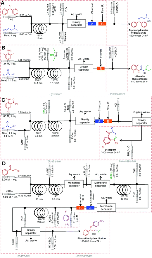 | ||
| Fig. 26 Continuous-flow synthesis of diphenhydramine hydrochloride, lidocaine hydrochloride, diazepam and fluoxetine hydrochloride.9 | ||
4. Conclusions
This Review examines the continuous-flow multi-step syntheses of 22 APIs, or API related compounds, four natural products, and 20 multi-step transformations. These examples provide a general overview of this rapidly expanding and diverse area. Given the recent growth of the field, more complex multi-step syntheses are inevitable. In order to achieve this vision there must be a concomitant advancement in in-line purification, isolation, and continuous-flow technology. In this respect, harnessing the power of several approaches seems like an ideal path forward. As we strive to draw inspiration from Nature's multistep procedures, this Review will hopefully act as a starting point for those wishing to advance, and learn about the many benefits of continuous-flow chemistry.Acknowledgements
JB and CLR wish to acknowledge the Government of South Australia and the Australian Research Council.Notes and references
- M. Planchestainer, M. L. Contente, J. Cassidy, F. Molinari, L. Tamborini and F. Paradisi, Green Chem., 2017 10.1039/C6GC01780K.
- J. Britton, C. L. Raston and G. A. Weiss, Chem. Commun., 2016, 52, 10159–10162 RSC.
- D.-T. Tran, J.-S. Chang and D.-J. Lee, Appl. Energy, 2017, 185, 376–409 CrossRef CAS.
- M. Asadi, J. F. Hooper and D. W. Lupton, Tetrahedron, 2016, 72, 3729–3733 CrossRef CAS.
- A. Gunther and K. F. Jensen, Lab Chip, 2006, 6, 1487–1503 RSC.
- B. Gutmann, D. Cantillo and C. O. Kappe, Angew. Chem., Int. Ed., 2015, 54, 6688–6728 CrossRef CAS PubMed.
- L. Capretto, W. Cheng, M. Hill and X. Zhang, in Microfluidics: Technologies and Applications, ed. B. Lin, Springer Berlin Heidelberg, Berlin, Heidelberg, 2011, pp. 27–68, DOI:10.1007/128_2011_150.
- C. Wiles and P. Watts, Green Chem., 2012, 14, 38–54 RSC.
- A. Adamo, R. L. Beingessner, M. Behnam, J. Chen, T. F. Jamison, K. F. Jensen, J.-C. M. Monbaliu, A. S. Myerson, E. M. Revalor, D. R. Snead, T. Stelzer, N. Weeranoppanant, S. Y. Wong and P. Zhang, Science, 2016, 352, 61–67 CrossRef CAS PubMed.
- J. Wegner, S. Ceylan and A. Kirschning, Chem. Commun., 2011, 47, 4583–4592 RSC.
- P. J. Kitson, S. Glatzel, W. Chen, C.-G. Lin, Y.-F. Song and L. Cronin, Nat. Protoc., 2016, 11, 920–936 CrossRef CAS PubMed.
- D. Webb and T. F. Jamison, Chem. Sci., 2010, 1, 675–680 RSC.
- S. V. Ley, D. E. Fitzpatrick, R. J. Ingham and R. M. Myers, Angew. Chem., Int. Ed., 2015, 54, 3449–3464 CrossRef CAS PubMed.
- A. R. Bogdan, M. Charaschanya, A. W. Dombrowski, Y. Wang and S. W. Djuric, Org. Lett., 2016, 18, 1732–1735 CrossRef CAS PubMed.
- C. Spiteri and J. E. Moses, Synlett, 2012, 1546–1548 CAS.
- H. Kim, H.-J. Lee and D.-P. Kim, Angew. Chem., Int. Ed., 2016, 55, 1422–1426 CrossRef CAS PubMed.
- N. Pagano, A. Herath and N. D. P. Cosford, J. Flow Chem., 2011, 1, 28–31 CrossRef CAS PubMed.
- P. Li and S. L. Buchwald, Angew. Chem., Int. Ed., 2011, 50, 6396–6400 CrossRef CAS PubMed.
- S. Glockner, D. N. Tran, R. J. Ingham, S. Fenner, Z. E. Wilson, C. Battilocchio and S. V. Ley, Org. Biomol. Chem., 2015, 13, 207–214 CAS.
- D. X. Hu, M. O’Brien and S. V. Ley, Org. Lett., 2012, 14, 4246–4249 CrossRef CAS PubMed.
- H. Ishitani, Y. Saito, T. Tsubogo and S. Kobayashi, Org. Lett., 2016, 18, 1346–1349 CrossRef CAS PubMed.
- C. E. M. Salvador, B. Pieber, P. M. Neu, A. Torvisco, C. Kleber, Z. Andrade and C. O. Kappe, J. Org. Chem., 2015, 80, 4590–4602 CrossRef CAS PubMed.
- D. Lücke, T. Dalton, S. V. Ley and Z. E. Wilson, Chem. – Eur. J., 2016, 22, 4206–4217 CrossRef PubMed.
- T. Noel and S. L. Buchwald, Chem. Soc. Rev., 2011, 40, 5010–5029 RSC.
- W. Shu, L. Pellegatti, M. A. Oberli and S. L. Buchwald, Angew. Chem., Int. Ed., 2011, 50, 10665–10669 CrossRef CAS PubMed.
- L.-M. Tan, Z.-Y. Sem, W.-Y. Chong, X. Liu, P. Hendra, W. L. Kwan and C.-L. K. Lee, Org. Lett., 2013, 15, 65–67 CrossRef CAS PubMed.
- T. N. Glasnov and C. O. Kappe, Adv. Synth. Catal., 2010, 352, 3089–3097 CrossRef CAS.
- N. M. Roda, D. N. Tran, C. Battilocchio, R. Labes, R. J. Ingham, J. M. Hawkins and S. V. Ley, Org. Biomol. Chem., 2015, 13, 2550–2554 CAS.
- J. A. Souto, R. A. Stockman and S. V. Ley, Org. Biomol. Chem., 2015, 13, 3871–3877 CAS.
- D. Webb and T. F. Jamison, Org. Lett., 2012, 14, 2465–2467 CrossRef CAS PubMed.
- J. Britton, J. W. Castle, G. A. Weiss and C. Raston, Chem. – Eur. J., 2016, 31, 10773–10776 CrossRef PubMed.
- L. Dalla-Vechia, B. Reichart, T. Glasnov, L. S. M. Miranda, C. O. Kappe and R. O. M. A. de Souza, Org. Biomol. Chem., 2013, 11, 6806–6813 CAS.
- Y. Lv, Z. Yu and W. Su, Org. Process Res. Dev., 2011, 15, 471–475 CrossRef CAS.
- L. Pellegatti and J. Sedelmeier, Org. Process Res. Dev., 2015, 19, 551–554 CrossRef CAS.
- P. R. D. Murray, D. L. Browne, J. C. Pastre, C. Butters, D. Guthrie and S. V. Ley, Org. Process Res. Dev., 2013, 17, 1192–1208 CrossRef CAS.
- S. Newton, C. F. Carter, C. M. Pearson, L. de C. Alves, H. Lange, P. Thansandote and S. V. Ley, Angew. Chem., Int. Ed., 2014, 53, 4915–4920 CrossRef CAS PubMed.
- M. Brasholz, J. M. Macdonald, S. Saubern, J. H. Ryan and A. B. Holmes, Chem. – Eur. J., 2010, 16, 11471–11480 CrossRef CAS PubMed.
- A. R. Bogdan, S. L. Poe, D. C. Kubis, S. J. Broadwater and D. T. McQuade, Angew. Chem., Int. Ed., 2009, 48, 8547–8550 CrossRef CAS PubMed.
- D. R. Snead and T. F. Jamison, Angew. Chem., Int. Ed., 2015, 54, 983–987 CrossRef CAS PubMed.
- D. Kopetzki, F. Lévesque and P. H. Seeberger, Chem. – Eur. J., 2013, 19, 5450–5456 CrossRef CAS PubMed.
- K. Gilmore, D. Kopetzki, J. W. Lee, Z. Horvath, D. T. McQuade, A. Seidel-Morgenstern and P. H. Seeberger, Chem. Commun., 2014, 50, 12652–12655 RSC.
- T. Tsubogo, H. Oyamada and S. Kobayashi, Nature, 2015, 520, 329–332 CrossRef CAS PubMed.
- P. L. Heider, S. C. Born, S. Basak, B. Benyahia, R. Lakerveld, H. Zhang, R. Hogan, L. Buchbinder, A. Wolfe, S. Mascia, J. M. B. Evans, T. F. Jamison and K. F. Jensen, Org. Process Res. Dev., 2014, 18, 402–409 CrossRef CAS.
- P. Zhang, M. G. Russell and T. F. Jamison, Org. Process Res. Dev., 2014, 18, 1567–1570 CrossRef CAS.
- S. Mascia, P. L. Heider, H. Zhang, R. Lakerveld, B. Benyahia, P. I. Barton, R. D. Braatz, C. L. Cooney, J. M. B. Evans, T. F. Jamison, K. F. Jensen, A. S. Myerson and B. L. Trout, Angew. Chem., Int. Ed., 2013, 52, 12359–12363 CrossRef CAS PubMed.
- C. A. Correia, K. Gilmore, D. T. McQuade and P. H. Seeberger, Angew. Chem., Int. Ed., 2015, 54, 4945–4948 CrossRef CAS PubMed.
- D. Ghislieri, K. Gilmore and P. H. Seeberger, Angew. Chem., Int. Ed., 2015, 54, 678–682 CAS.
- S. Borukhova, T. Noël and V. Hessel, ChemSusChem, 2016, 9, 67–74 CrossRef CAS PubMed.
- Z. Qian, I. R. Baxendale and S. V. Ley, Chem. – Eur. J., 2010, 16, 12342–12348 CrossRef CAS PubMed.
- P. F. Carneiro, B. Gutmann, R. O. M. A. de Souza and C. O. Kappe, ACS Sustainable Chem. Eng., 2015, 3, 3445–3453 CrossRef CAS.
- J. Britton, J. M. Chalker and C. L. Raston, Chem. - Eur. J., 2015, 21, 10660–10665 CrossRef CAS PubMed.
Footnote |
| † Current address: Department of Chemistry, Massachusetts Institute of Technology, 77 Massachusetts Avenue, Cambridge, MA 02139, USA. E-mail: jbritton@mit.edu. |
| This journal is © The Royal Society of Chemistry 2017 |

