 Open Access Article
Creative Commons Attribution 3.0 Unported Licence
Shape-controlled continuous synthesis of metal nanostructures†
Victor
Sebastian‡
,
Christopher D.
Smith§
and
Klavs F.
Jensen
*
Department of Chemical Engineering, Massachusetts Institute of Technology, 77, Massachusetts Avenue, Cambridge, MA 02139, USA. E-mail: kfjensen@mit.edu
First published on 1st March 2016
Abstract
A segmented flow-based microreactor is used for the continuous production of faceted nanocrystals. Flow segmentation is proposed as a versatile tool to manipulate the reduction kinetics and control the growth of faceted nanostructures; tuning the size and shape. Switching the gas from oxygen to carbon monoxide permits the adjustment in nanostructure growth from 1D (nanorods) to 2D (nanosheets). CO is a key factor in the formation of Pd nanosheets and Pt nanocubes; operating as a second phase, a reductant, and a capping agent. This combination confines the growth to specific structures. In addition, the segmented flow microfluidic reactor inherently has the ability to operate in a reproducible manner at elevated temperatures and pressures whilst confining potentially toxic reactants, such as CO, in nanoliter slugs. This continuous system successfully synthesised Pd nanorods with an aspect ratio of 6; thin palladium nanosheets with a thickness of 1.5 nm; and Pt nanocubes with a 5.6 nm edge length, all in a synthesis time as low as 150 s.
Introduction
The controlled synthesis of nanomaterials has attracted significant attention in the last decade because the properties of nanocrystals are determined by their size, shape, structure and composition.1 Nanoparticles of different shapes possess different facets and orientations.2 The catalytic activity and selectivity of these atoms is correlated to their location and electronic structure3 and their performance in catalytic processes has been shown to be highly dependent on both the exposed facets of the nanocrystal and the particle's surface area.3 For example, the turnover rates and product selectivity of benzene hydrogenation is very sensitive to the platinum nanocrystal's surface coordination: producing only cyclohexane on Pt(100); and both cyclohexene and cyclohexane on Pt(111).4 Therefore, precise control of both the size and shape of the catalyst is essential to enhance the usefulness of these nanomaterials for optimal performance in structure–sensitive reactions.Solution-phase synthesis has demonstrated successes for controlling the size and shape of nanoparticles1,5 through the use of kinetic control along with different reducing agents and organic/inorganic additives to affect the natural growth habits of nanocrystals.6 Gaseous reducing agents, such as hydrogen or carbon monoxide, are known to control the shape of nanocrystals,5,7,8 permitting a delicate control of the growth kinetics and thus tailoring the shape and size of the nanostructures. However, current procedures require a synthesis time of several hours7,9 and the need for rigorous safety precautions due to the high toxicity and flammability of those gaseous agents.
Despite recent advances,10–12 it still remains a challenge to reliably produce faceted nanocrystals with the desired size and shape using rapid and easily scalable procedures that have a minimal environmental impact.9 In addition, these solution-phase approaches are traditionally run in small volume batch-reactors, where they suffer from batch-to-batch variations and the commercial scalability of these micro-batch systems remains a challenge.9,13
These inconveniences and our desire to implement safely a rapid screening program of nanomaterial production in a continuous fashion, have led to the utilization of a microfluidic reactor platform (MFR). Microreactor technology scales-down the reaction volume to take advantage of the large surface area to volume ratio, improving heat and mass transport, which consequently promotes more uniform heating and mixing.14,15 Rapid reactions can be better controlled in a MFR by using a segmented flow approach, where circulation within the slugs enhances mixing and improves mass transfer rates across the interface. This approach also enables the design of new synthetic protocols and improves control of the steps that govern nanocrystal synthesis, namely nucleation and growth.16
Our synthetic method is based on gas–liquid multi-phase flow in which the gas phase acts as the: (1) dispersed phase, to segment the liquid flow, promoting the gas–liquid mass transfer and diminishing the size and shape heterogeneity; (2) reducing agent; (3) capping agent, to block metal addition to certain metal surfaces.
The key to obtaining only one nanocrystal shape is to keep a tight rein on both the kinetic and thermodynamic factors,1 which is facilitated by the use of continuous flow approaches. Micro and meso scale flow reactors have been used to improve particle size distribution of nanomaterials17,18 and to effect shape control.10–12,19–21 Herein, we report a MFR approach to synthesize anisotropic palladium and platinum nanostructures under kinetic control, in order to fine tune the size and shape of nanocrystals, as part of a continuous flow system. Gas–liquid segmented flow in a silicon–pyrex MFR is used as a versatile tool that not only realises better control of the nanostructures size distribution, but also achieves excellent shape control. The microreactor is designed to withstand high pressure and comprises a cooled mixing zone, where the reactants are efficiently mixed, and a reaction zone where the maximum temperature achievable is 350 °C. The experiments are run with residence times as low as 150 s and at temperatures ranging from 35–250 °C, permitting a new set of conditions to be evaluated every few minutes with minimal amounts of the precious metal precursor required. In this report, we explore the conditions that promote the formation of Pt nanocubes, Pd nanorods, as well as Pd triangular and hexagonal nanosheets with Surface Plasmon Resonance (SPR) properties.
Results and discussion
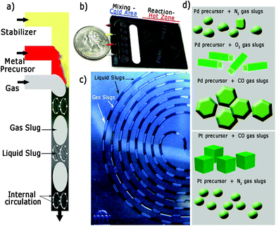
Fig. 1 illustrates the silicon/pyrex MFR utilised in this work to synthesize the differently shaped palladium and platinum nanocrystals. The reactor consisted of two zones (mixing-cold and reaction-hot) separated by a thermally isolating halo etch.22 The mixing zone was formed by meandering channels to promote passive mixing and maintained at 15 °C using a recirculating coolant to avoid nucleation. The reaction zone (volume = 100 μL) could be heated up to temperatures as high as 250 °C and the system was pressurized to 120 psi (8.3 bar) in order to increase both the gas solubility in the liquid phase and to enable the use of water as solvent at high temperature (Fig. S1 in ESI†). Two liquid (L1 and L2) and one gas stream were mixed on the chip and attained a steady gas–liquid segmented flow (Fig. 1a and c and Fig. S1 in ESI†). Due to internal circulation inside these liquid/gas segments (Fig. 1a),23,24 intense inter-phase mixing is promoted, which is important for the gas to modify the crystallization kinetics in the liquid phase. In addition, the particle size distribution is governed by the slip velocity between the two phases and internal mixing in the continuous-phase slugs.24 Both the velocity difference between the two phases and the slug length govern the nature of internal circulation in the slug and hence the particle size.24 Consequently, a high slip velocity and short slugs will yield a narrow particle size distribution, and a very narrow residence time distribution profile.24,25Liquid slugs with a volume up to 150 nL were produced with high fidelity during the operation of the MFR at different residence times (Fig. 1c). This continuous MFR system is inherently repeatable as all slugs act as identical reaction vessels, which is necessary to assure the same kinetic conditions in order to obtain the desired shape-controlled nanomaterials (Fig. 1d).23,24
Synthesis of faceted Pd nanostructures – synthesis with O2 segmented flow
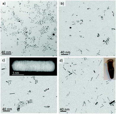
Oxidative etching is the fundamental driving force for the anisotropic growth of palladium nanorods and it is caused by both the oxygen dissolved in the reaction media and the chloride anions from the Pd precursor.26 Localized oxidative etching can activate the surface of the nanocrystals by selectively dissolving defect zones in nuclei whilst the presence of ethylene glycol (as reductant) and bromide ions (capping agent) ensures the anisotropic growth of palladium nanocrystals. When the dissolution of Pd atoms caused by oxidative etching is fast enough to activate the surface but slower than the atom addition, anisotropic growth takes place and the fcc habit of Pd can be broken. We have previously shown that oxygen–liquid segmented flow enhances oxidative etching relative to other methods11 since is difficult to control the oxygen content in the reaction media in batch, or when using a single phase microreactor, which has the additional problems of fouling by salt crystallization.Fig. 2 illustrates the TEM micrographs of the as-made nanorods obtained when O2 slugs diffuse into liquid slugs formed by the mixing at different proportions of L1 and L2 streams. Anisotropic growth is clearly promoted by the use of oxygen–liquid segmented flow, decreasing the number of nanocubes and Wulf polyhedrons when compared to a laminar flow pattern without O2 slugs (Fig. S2 in ESI†). Pd nanorods were only obtained at a reaction temperature higher than 160 °C, whereas shapeless nanoparticles were produced at lower temperatures.
Xiong et al.26 have synthesised similar Pd nanorods in batch and have proposed that this success was due to the control of three variables: (1) bromide adsorption; (2) kinetics of nucleation/reduction; and (3) oxidative etching. The microfludic approach makes it feasible to synthesize Pd nanorods in a continuous fashion and in a time scale lower than 2 minutes. The batch reactor required 1 hour at 100 °C to produce the same results.26
The anisotropic growth of Pd nanostructures can be modified by tuning the Pd(II) reduction rate by varying the ratio of the liquid streams L1 and L2. L2 is composed of ethylene glycol (EG) and polyvinyl pyrrolidone (PVP) whereas L1 contains the palladium precursor (Na2PdCl4). The concentration of EG, the reducing agent, will affect the rate of reduction of Pd ions and it was found that the nanorod aspect ratio could be increased from 2.5 to 6 by increasing the L2/L1 flow ratio from 0.25 to 1.8, respectively (Fig. 2a–d and S3-c in ESI†). This trend is in full agreement with Xiong et al.26 and can be rationalized in terms of a diffusion limitation process in which the increase in Pd0 atoms in the growth media increases with the EG content, which facilitates the preferential growth along the a-axis by atomic addition. Nevertheless, once the L2/L1 flow ratio is higher than 4 (Fig. S3 in ESI†) the nanorods aspect ratio decreased implying that an optimum has been found. Therefore, a low content of EG reduces the reduction rate and the atom addition rate, while a high content of EG increases the nucleation and reduction rate, in a such a way that the reduction rate of palladium ions exceeds the atom addition rate and instead small palladium clusters are formed.
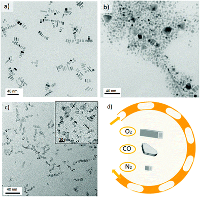
The rate of oxidative etching and hence the nanorods aspect ratio can be also controlled by modification of the ratio between the oxygen and liquid flow. Fig. 3a shows a TEM image of nanorods synthesized under a low O2–liquid ratio. The decrease in the O2 to liquid ratio increases the slug length, affecting negatively to the gas–liquid mass transfer27 and hence the oxygen supply to the liquid phase. Consequently, the anisotropic growth is less favoured; under such conditions nanorods with a low aspect ratio are produced. Although the effect of the O2–liquid segmented flow is clear, oxygen was replaced by nitrogen in order to study if the mixing enhancement due to segmentation influences nanorod formation; thereby decoupling this factor from the oxidative etching mechanism. Fig. 3b shows that without oxygen, anisotropic growth does not occur and shapeless nanoparticles, as well as short aspect ratio nanorods, are formed; mainly due to the chloride anion's contribution to oxidative etching. The most striking differences, with respect to the approach reported by Kim et al.,19 are that the Pd nanostructures shape, size and aspect ratio can effectively be tuned by modifying the composition of both gas and liquid slugs. An additional advantage of our gas–liquid segmented flow system, as compared to non-soluble liquid–liquid segmented flow, is the simplicity of nanoparticle separation and processing after the production step by straightforward precipitation.
Synthesis of faceted Pd nanostructures – synthesis with CO segmented flow
When the Pd nanorod synthesis conditions were repeated using carbon monoxide (CO)–liquid segmented flow, it was observed that CO promoted the anisotropic growth of palladium into thin nanosheets (Fig. 3c). This can be rationalised in terms of the high CO affinity for metal nanoparticles, being selectively chemisorbed at different facets and active sites.28 In fact, this property has been widely used to characterize metal catalysts using IR spectroscopy.29 Furthermore, CO has been reported to act as both a soft reducing agent for the synthesis of hexagonal and triangular Pd nanosheets;30,31 as well as other metal nanostructures;32 and as a capping agent because of its binding affinity.1 Such preferential adsorption can effectively hinder the growth of a particular facet, promoting atom addition to other crystallographic planes. Therefore, the identity of the gas slug and its chemical interaction with the palladium atoms has a profound impact on the shape-controlled growth of a nanocrystal.An in-depth study into the influence of synthesis temperature on the nanocrystal's shape, demonstrated that triangular nanosheets were obtained at a temperature as low as 35 °C (Fig. S4-b in ESI†). In addition, the liquid slugs progressively turn into dark-blue colour solutions as they are flowing through the chip reactor.
These observations confirmed the role of CO as reducing agent because the liquid segmentation with oxygen or nitrogen required a temperature higher than 110 °C to reduce Na2PdCl4. On the other hand, as the synthesis temperature was increased, no shape control was achieved and inhomogeneous nanosheets were obtained (Fig. 3c and Fig. S4 in ESI†). The results suggested that the presence of polyvinyl pyrrolidone (PVP), Br− and CO were not sufficient to control the nanosheet's shape. The addition of a quaternary ammonium salt, tetradecyltrimethylammonium bromide (TTABr), enabled better control of the nanosheet's shape but also promoted a fouling process on the microchannel walls, which rapidly blocked the microreactor. Dimethylformamide (DMF), a polar aprotic solvent, was selected to inhibit the fouling process by enhancing the solubility of TTABr in the liquid slugs.
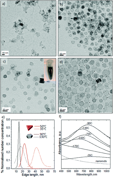
Fig. 4 shows the Pd nanosheets obtained under our second set of conditions in the presence of PVP, TTABr, KBr, DMF, water and Na2PdCl4. By varying the synthesis temperature, the shape could be changed between trigonal and hexagonal nanosheets. At 35 °C the nanostructures were composed of sharp triangular nanosheets with a mean edge length of 41 ± 12.8 nm (Fig. 4a and e). Increasing the temperature to 50 °C predominantly formed triangular nanosheets with a mean edge length of 23 ± 7.0 nm (Fig. 4b and e), but some truncated trigonal and hexagonal nanosheets were also obtained. Hexagonal nanosheets were only obtained at temperatures higher than 50 °C, producing the most homogenous at 90 °C with a mean edge length of 14.4 ± 2.0 nm (Fig. 4c and e, and Fig. S5-a in ESI†). Temperatures higher than 90 °C promoted the inhomogenous growth of hexagonal nanosheets and at 130 °C formed both nanosheets and polyhedrons (Fig. 4d, and Fig. S5-b–d in ESI†).
Finally, the nanosheet morphology disappeared at 170 °C, resulting in hybrid structures composed of short wires and curled sheets (see Fig. S5-e in ESI†). The observed anisotropic growth of; the palladium nanosheets is due to carbon monoxide binding to the Pd nanostructure. This binding depends on the atom distribution (facets) and the adsorption temperature CO coverage decreases with increasing temperature and it is known that CO molecules bind stronger to {111} planes than to {100}.33,34 Consequently, the fast mass transfer across the gas–liquid slug interface ensures the presence of enough CO to direct both the adsorption of CO and the reduction of Pd ions at only 35 °C and a residence time of 150 s. The slow reduction rate of CO at low temperature and its preferential adsorption to basal {111} planes promoted kinetic control and the confined growth of triangular nanosheets with uniform thickness (1.5 nm). By increasing the temperature, the reduction rate is notably higher but the CO coverage diminishes, resulting in another morphology – hexagonal nanosheets.35 Kinetic control is more difficult to maintain above 110 °C because the reduction rate increases and CO absorption is not favoured, leading to inhomogeneous growth. Above 170 °C the poor adsorption of CO on basal planes results in other Pd nanostructures being obtained.
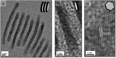
The nanosheets were sensitive to electron-beam irradiation during TEM characterization, which caused the observed damage seen in Fig. 4 and this susceptibility is clearly related to the ultrathin nanosheets obtained. Advantageously, the tendency of the palladium nanosheets to stack (Fig. 4c) enabled their direct thickness to be measured by HRTEM (Fig. 5a and b). The average thickness was found to be 1.5 nm, which corresponds to less than 9 atomic layers. Lattice fringes with an interplanar spacing of 0.245 nm were calculated (Fig. 5c), which can be ascribed to the 1/3{422} reflection of fcc palladium. This is in full agreement with previous observations of palladium nanoplatelets and suggest that the palladium nanosheets are bound by two {111} basal planes.31,35,36
The clear pyrex top of the MFR allowed us to observe the colour change of the liquid slugs from dark orange to dark blue as they flowed from the inlet to the outlet. This colour change implied that the nanostructures generated under segmented flow exhibited optical properties (Fig. 4f). The UV-visible absorption spectra of the Pd nanosheets confirmed that the Surface Plasmon Resonance (SPR) featured a high sensitivity of the maxima to the synthesis temperature and nanosheets geometry. Interestingly, triangular nanosheets exhibited a broad absorption starting at 460 nm to the near-infrared (NIR) region (Fig. 4f).
The SPR peak blue-shifted as the synthesis temperature increased to 50 °C and the edge length decreased (Fig. 4f and Fig. S5-f in ESI†). The hexagonal nanosheets obtained from 50 °C to 110 °C displayed a SPR red-shift from 700 to 750 nm but beyond 110 °C the SPR peak of the nanosheets blue-shifted again (Fig. 4f and Fig. S5-f in ESI†). Finally, the SPR feature disappears at 170 °C even though the SPR would be expected to increase as the edge length of hexagonal nanosheets and synthesis temperature increase.36 The inhomogeneous control of the nanosheets size and the presence of twinned nanoparticles could explain this tendency. These unique optical properties in the NIR have been attributed to the ultrathin nature of Pd nanosheets.35,36 The nanosheets retained the SPR features after synthesis which reduces the possibility that the plasmon adsorption derived from the charge transfer between CO and palladium. Nanoparticle ageing after several weeks promoted the formation of defects on the surface and quenching of SPR absorption (Fig. S6 in ESI†).
Our continuous system compares favourably to the results of intensive traditional batch-type reactors,31,36 facilitating short reaction times and rapid synthesis condition screening (∼10 minutes between each collection). Additionally, the CO segmented flow MFR operated at elevated temperatures and pressures while confining a potentially toxic reagent in a slug with a volume as small as a nanolitres. Those conditions are difficult to achieve in a conventional batch reactor.
Synthesis of faceted Pt nanostructures with CO segmented flow
Previous research has shown that not only the presence of small adsorbates37 but also the choice of metal precursor is critical for the formation of faceted nanoparticles.38 Pt nanocrystals with high-energy facets have previously been reported using both aqueous and non-aqueous synthetic routes.6 Therefore, using the previously described equipment we set out to synthesize Pt nanostructures in flow.Pt nanoparticle synthesis under aqueous conditions
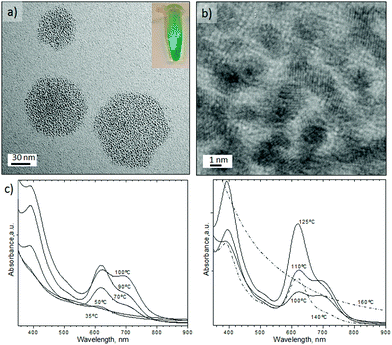
An aqueous stream of potassium tetrachloroplatinate, K2PtCl4 segmented with CO at 25 °C and 150 s residence time did not form any nanostructures. Surprisingly, at temperatures above 35 °C a green solution was observed (see Fig. 6a), but above 160 °C the solution turned a light brown. Fig. 6a shows the Pt nanostructures synthesised at 125 °C, resulting in hexagonal aggregates of tiny Pt nanoparticles with an inhomogenous size distribution. HRTEM characterization revealed that the Pt nanoparticles had assembled into a polycrystalline structure with hexagonal shape (Fig. 6b and Fig. S7-a–c in ESI†). Between 35–140 °C the shape and structure of the platinum aggregates did not vary, but at 160 °C individual particles without hexagonal assembly were obtained (Fig. S7-d in ESI†).The most striking feature of the hexagonal Pt nanoparticles assembly is that they exhibit tuneable absorption peaks in the UV-Vis region. It can be seen in Fig. 6c that these nanostructures display two prominent absorption bands: a high energy band in the near UV (350–450 nm) and a low energy band in the visible (450–810 nm). It has been reported that Pt nanoparticles display a characteristic Surface Plasmon Resonance (SPR) at 215 nm,39 with a weak tail extending in the visible. But to our knowledge there has been no report of SPR in the UV-Vis region; although ultrathin metallic structures, such as the Pd nanosheets obtained in this work, can exhibit SPR.36 Interestingly, the optical properties of the Pt clusters disappeared after several days in contact with air (Fig. S8 in ESI†), which implies that the absorption of the Pt nanostructures arises from the charge transfer between platinum and CO.40 This feature suggest that the particles responsible for the spectrum are self-assemblies of Chini clusters [Pt3(CO)6]n−2,41,42 where n is the cluster nuclearity, which usually ranges from 1–10.
Chini clusters display a low energy band which is n dependant and permits the discrimination of clusters. High energy bands are also n dependent, but to a much lesser extent than the low energy bands.43 Chini clusters with n = 4 (blue-green colour) and n = 5 (yellow-green) display a maximum in the visible band at 620 and 710 nm, respectively.43 These values are in full agreement with the UV-Vis spectrum reported in Fig. 6c. Consequently, it appeared that Chini clusters with n = 4 were obtained between 50 and 70 °C or at temperatures higher than 125 °C. However, between 90–110 °C a mixture of Chini clusters with n = 4 and 5 were obtained (Fig. 6c). On the other hand, it is reported that the structural characterization of Pt-Chini clusters is challenging due to the low thermal stability.44,45 In fact, the TEM electron beam can thermally convert Pt-Chini clusters into nanoparticles,45 obtaining nanoparticles smaller than 2 nm.44
Pt nanoparticle synthesis under non-aqueous conditions
The non-aqueous synthetic route was carried out using platinum(II) acetylacetonate (Pt(acac)2) in mixtures containing oleylamine (OAm) and oleic acid (OLA) (Experimental section). Liquid stream L1 containing Pt(acac)2 and OAm was mixed with a second liquid stream L2 composed of OAm and OLA, allowing control of the OAm/OLA molar ratio. The liquid streams were also segmented using CO, obtaining gas–liquid slugs with a 1![[thin space (1/6-em)]](https://www.rsc.org/images/entities/char_2009.gif) :
:![[thin space (1/6-em)]](https://www.rsc.org/images/entities/char_2009.gif) 1, v
1, v![[thin space (1/6-em)]](https://www.rsc.org/images/entities/char_2009.gif) :
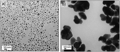
:![[thin space (1/6-em)]](https://www.rsc.org/images/entities/char_2009.gif) v flow. Contrary to our aqueous experiments with K2PtCl4, Pt(acac)2 did not generate any nanostructures at temperatures lower than 200 °C and the high temperatures required to reduce Pt(acac)2 implies that the platinum carbonyl clusters observed earlier are not formed. The nanocrystals obtained at 200 °C with OAm/OLA = 8.5, OLA/Pt = 60 (molar ratios) exhibited a high shape dispersity including nanorods, truncated nanocubes, nanocubes, triangle nanoplates and polyhedral nanocrystals (Fig. 7a).
v flow. Contrary to our aqueous experiments with K2PtCl4, Pt(acac)2 did not generate any nanostructures at temperatures lower than 200 °C and the high temperatures required to reduce Pt(acac)2 implies that the platinum carbonyl clusters observed earlier are not formed. The nanocrystals obtained at 200 °C with OAm/OLA = 8.5, OLA/Pt = 60 (molar ratios) exhibited a high shape dispersity including nanorods, truncated nanocubes, nanocubes, triangle nanoplates and polyhedral nanocrystals (Fig. 7a).
While faceted nanocrystals were obtained with CO segmented flow, only shapeless nanoparticles were obtained if N2 gas replaced CO (see Fig. 7b). This is to be expected from the preferential adsorption of CO onto Pt atoms localised on the (100) surfaces.8 Additionally, the OAm/OLA ratio is an important factor for controlling the formation of faceted Pt nanocrystals46 because neither OAm nor OLA alone leads to the formation of Pt nanocrystals with (100) facets.46 In fact, it is the co-adsorption of CO and OAm onto (100) surfaces47 that promotes the fast growth of other facets, lowering the binding energy, and therefore, the total surface energy on (100). This implies that the CO-amine co-adsorption stabilises the (100) facets, resulting in the addition of Pt atoms to (111) and thus leading to formation of (100) faceted nanocrystals.47 An added complication is CO's role as reducing agent, since this can alter the kinetics of the nucleation-growth process.48 Consequently, manipulation of these factors including CO content, OAm/OLA ratio, OLA/Pt ratio, temperature and residence time is required to control the synthesis of nanocrystals with (100) facets. A final consideration relevant to flow is that the concentration of the Pt precursor is crucial to avoid clogging of the microchannels during synthesis process.
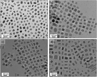
Decreasing the OAm/OLA molar ratio to 3.8 permitted the formation of well-defined nanocrystals (Fig. 8) consistent with a previous study.46 The results of increasing the concentration of Pt(acac)2 at OLA/Pt = 45 proved that smaller faceted nanocrystals are obtained as a consequence of fast nucleation process (see Fig. 8a). Unfortunately, the microchannels quickly became clogged because the microreactor walls served as nucleation initiators. Decreasing the Pt concentration to OLA/Pt = 150 still permitted the formation of (100) faceted nanocrystals. At 230 °C Pt nanobars and nanocubes were obtained without any control on the edge length (Fig. 8d), whereas at 200 °C the most homogenous nanocrystals were obtained where the nanobar morphology was practically avoided (Fig. 8a). These results suggest that at the 200 °C the Pt atomic addition is fast enough to promote the anisotropic growth of Pt nanocrystals.26 In addition, at higher temperatures the low solubility of CO in the liquid phase decreases the coverage of (100) facets, increasing the surface energy and promoting anisotropic growth of different faceted nanostructures.
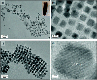
The Pt concentration was further decreased (OLA/Pt = 230) to promote the slow growth of {100} faceted nanocrystals from nuclei at 200 °C and OAm/OLA = 3.8. Under these synthetic conditions, perfectly cubic faceted nanocrystals were formed with sharp edges and a narrow size distribution (see Fig. 9a–c). The most striking aspect of these results is that Pt nanocubes with an average edge length of 5.6 nm could be obtained in a synthesis time as small as 150 s. It should be highlighted that the synthesis of Pt nanocubes by conventional batch reactors is reported to take several hours.46–49 The uniform size distribution of the nanocubes enabled them to assemble into long-range ordered arrays, creating even 3D-structured super lattices (Fig. 9c and Fig. S7-e and f in ESI†). HRTEM of a single Pt nanocube revealed an interplanar distance of 0.19 nm, which is consistent with the lattice spacing of the {100} planes of the fcc platinum structure (Fig. 9d). Furthermore, the well-resolved lattice fringes indicated the single crystallinity of the Pt nanocubes.
Metal carbonyl inputs46,49 can facilitate the nucleation and direct the growth of Pt nanocubes, but we have demonstrated the synthesis of Pt nanocubes with high crystallinity and shape uniformity from easily accessible metal salts without recourse to difficult to handle and purify, and potentially toxic metal carbonyls.
Experimental
Reactants
The following reactant materials were used in the experiments: ethylene glycol (EG, Aldrich), sodium palladium(II) chloride (Na2PdCl4, Aldrich), potassium tetrachloroplatinate(II) (K2PdCl4, Aldrich), platinum(II) acetylacetonate (Pt(acac)2, Adrich), potasium bromide (KBr, Aldrich), polyvinyl pyrrololidone (Aldrich MW = 55![[thin space (1/6-em)]](https://www.rsc.org/images/entities/char_2009.gif) 000), tetradecyltrimethy-lammonium bromide (TTABr, Aldrich) dimethylformamide (DMF, EMD chemicals), oleic acid, carbon monoxide (CO, Airgas), Oxygen (O2, Airgas) and Nitrogen (N2, Airgas).
000), tetradecyltrimethy-lammonium bromide (TTABr, Aldrich) dimethylformamide (DMF, EMD chemicals), oleic acid, carbon monoxide (CO, Airgas), Oxygen (O2, Airgas) and Nitrogen (N2, Airgas).
Microfluidic reactor (MFR)
A silicon microreactor was fabricated by deep-reactive ion etching to form a square-cross-section channel (400 μm on the side) with a reactive volume of 100 μL and (etched from the backside) in/outlet through-holes. The channel side of the etched wafer was capped by anodically bonding to a pyrex wafer. The chip device includes three fluid inlet ports and one outlet port. The microfluidic reactors consisted of two zones, a cold inlet/outlet/mixing zone and a hot reaction zone (100 μL volume), separated by a thermally isolating halo etch that allowed a temperature gradient of over 25 °C mm−1.Microfluidic system description
The flow setup is depicted in Fig. S1.† The liquid input is driven using two Harvard syringe pumps whilst the gas phase is added using a UNIT mass flow meter. The gas/liquid streams meet at the microreactor mixing cold zone. The gas flow is controlled such that at room temperature the desired liquid![[thin space (1/6-em)]](https://www.rsc.org/images/entities/char_2009.gif) :
:![[thin space (1/6-em)]](https://www.rsc.org/images/entities/char_2009.gif) gas v
gas v![[thin space (1/6-em)]](https://www.rsc.org/images/entities/char_2009.gif) :
:![[thin space (1/6-em)]](https://www.rsc.org/images/entities/char_2009.gif) v slug flow regime is enforced. The initial mixing zone was cooled to 15 °C using a recirculating chiller before entering the hot zone of the reactor. Throughout these experiments the system was pressurized to 120 psi using a N2 cylinder. The temperature in the reaction zone was controlled with a PID temperature controller. As an example a total flow rate of 40 μL min−1 (20 μL min−1 liquid + 20 μL min−1 gas) ensures a residence time of 2.5 min (150 s) in the hot zone. The samples were eluted from the reagent loop with ethanol, precipitated with cyclohexane spun down and filtered. The samples were analyzed using UV absorption (Agilent 8453 UV-Visible spectrophotometer) and transmission electron microscopy (JEOL JEM 200CX and HRTEM JEOL 2010 microscopes at an accelerating voltage of 200 kV).
v slug flow regime is enforced. The initial mixing zone was cooled to 15 °C using a recirculating chiller before entering the hot zone of the reactor. Throughout these experiments the system was pressurized to 120 psi using a N2 cylinder. The temperature in the reaction zone was controlled with a PID temperature controller. As an example a total flow rate of 40 μL min−1 (20 μL min−1 liquid + 20 μL min−1 gas) ensures a residence time of 2.5 min (150 s) in the hot zone. The samples were eluted from the reagent loop with ethanol, precipitated with cyclohexane spun down and filtered. The samples were analyzed using UV absorption (Agilent 8453 UV-Visible spectrophotometer) and transmission electron microscopy (JEOL JEM 200CX and HRTEM JEOL 2010 microscopes at an accelerating voltage of 200 kV).
Synthesis of palladium nanorods
A liquid stream (L1) composed of ultra-pure water, KBr and Na2PdCl4 solution was prepared; the molar ratio Na2PdCl4/H2O was varied from 1/5000 to 1/1100. The molar ratio KBr/Na2PdCl4 was kept constant at 35. Liquid stream L2 was prepared by dissolving PVP in ethylene glycol with an EG/PVP ratio equal to 175. Reactants were introduced at the mixing zone in two separate fluid streams (L1 and L2), insuring good control of the flow rates. The ratio of L2 and L1 (L2/L1) was varied from 0.25 to 1.8. The gas/liquid flow ratios were varied from 0.8 to 3.5. Oxygen and nitrogen were used as the gas stream to create gas/liquid segmented flow. The pressure inside the reactor was maintained constant at 120 psi and the residence time was varied from 10 to 150 s.Synthesis of shapeless Pd nanosheets
A liquid stream (L1) composed of ultra-pure water, KBr, and Na2PdCl4 was mixed in the MFR with a liquid stream (L2) composed of PVP and ethlyene glycol in a volumetric flow ratio of L2/L1 = 1.8. The molar ratio of Na2PdCl4/H2O, Na2PdCl4/KBr in L1 stream were 1![[thin space (1/6-em)]](https://www.rsc.org/images/entities/char_2009.gif) :
:![[thin space (1/6-em)]](https://www.rsc.org/images/entities/char_2009.gif) 1100 and 1
1100 and 1![[thin space (1/6-em)]](https://www.rsc.org/images/entities/char_2009.gif) :
:![[thin space (1/6-em)]](https://www.rsc.org/images/entities/char_2009.gif) 35, respectively. The molar ratio of PVP (monomer)/EG in L2 liquid stream was 1
35, respectively. The molar ratio of PVP (monomer)/EG in L2 liquid stream was 1![[thin space (1/6-em)]](https://www.rsc.org/images/entities/char_2009.gif) :
:![[thin space (1/6-em)]](https://www.rsc.org/images/entities/char_2009.gif) 175. The liquid streams (L1 + L2) were mixed with carbon monoxide to obtain shapeless nanosheets. The gas/liquid volumetric flow ratio was 1, with a total gas/liquid segmented flow of 40 μL min−1. The pressure inside the reactor was maintained constant at 120 psi and the residence time was 150 s.
175. The liquid streams (L1 + L2) were mixed with carbon monoxide to obtain shapeless nanosheets. The gas/liquid volumetric flow ratio was 1, with a total gas/liquid segmented flow of 40 μL min−1. The pressure inside the reactor was maintained constant at 120 psi and the residence time was 150 s.
Synthesis of triangular/hexagonal Pd nanosheets
A liquid stream (L1) composed of ultra-pure water, KBr, PVP and Na2PdCl4 was mixed in the MFR with a liquid stream (L2) composed of DMF and TTABr in a volumetric flow ratio of L2/L1 = 4. The molar ratio of Na2PdCl4/H2O, Na2PdCl4/KBr and Na2PdCl4/PVP(monomer) in L1 stream was 1![[thin space (1/6-em)]](https://www.rsc.org/images/entities/char_2009.gif) :
:![[thin space (1/6-em)]](https://www.rsc.org/images/entities/char_2009.gif) 700, 1
700, 1![[thin space (1/6-em)]](https://www.rsc.org/images/entities/char_2009.gif) :
:![[thin space (1/6-em)]](https://www.rsc.org/images/entities/char_2009.gif) 35 and 1
35 and 1![[thin space (1/6-em)]](https://www.rsc.org/images/entities/char_2009.gif) :
:![[thin space (1/6-em)]](https://www.rsc.org/images/entities/char_2009.gif) 9, respectively. The molar ratio of DMF/TTAB in L2 liquid stream was 240
9, respectively. The molar ratio of DMF/TTAB in L2 liquid stream was 240![[thin space (1/6-em)]](https://www.rsc.org/images/entities/char_2009.gif) :
:![[thin space (1/6-em)]](https://www.rsc.org/images/entities/char_2009.gif) 1. The liquid streams (L1 and L2) were mixed with the carbon monoxide stream (CO/liquid volumetric flow ratio = 1), resulting in a total gas/liquid segmented flow of 40 μL min−1. The pressure inside the reactor was maintained at 120 psi and the residence time was 150 s.
1. The liquid streams (L1 and L2) were mixed with the carbon monoxide stream (CO/liquid volumetric flow ratio = 1), resulting in a total gas/liquid segmented flow of 40 μL min−1. The pressure inside the reactor was maintained at 120 psi and the residence time was 150 s.
Synthesis of Pt Chini clusters
Ultra-pure water, KBr, PVP and K2PtCl4 (liquid stream L1) was mixed in the MFR with liquid stream L2, composed of DMF and TTABr, in a volumetric flow ratio of L2/L1 = 4. The molar ratio of Na2PdCl4/H2O, Na2PdCl4/KBr and Na2PdCl4/PVP(monomer) in L1 stream was 1![[thin space (1/6-em)]](https://www.rsc.org/images/entities/char_2009.gif) :
:![[thin space (1/6-em)]](https://www.rsc.org/images/entities/char_2009.gif) 700, 1
700, 1![[thin space (1/6-em)]](https://www.rsc.org/images/entities/char_2009.gif) :
:![[thin space (1/6-em)]](https://www.rsc.org/images/entities/char_2009.gif) 35 and 1
35 and 1![[thin space (1/6-em)]](https://www.rsc.org/images/entities/char_2009.gif) :
:![[thin space (1/6-em)]](https://www.rsc.org/images/entities/char_2009.gif) 9, respectively. The molar ratio of DMF/TTAB in L2 liquid stream was 240
9, respectively. The molar ratio of DMF/TTAB in L2 liquid stream was 240![[thin space (1/6-em)]](https://www.rsc.org/images/entities/char_2009.gif) :
:![[thin space (1/6-em)]](https://www.rsc.org/images/entities/char_2009.gif) 1. The liquid streams L1 and L2 were mixed with a carbon monoxide stream (CO/liquid volumetric flow ratio = 1), with a total gas/liquid segmented flow of 40 μL min−1. The pressure inside the reactor was maintained at 120 psi and the residence time was 150 s.
1. The liquid streams L1 and L2 were mixed with a carbon monoxide stream (CO/liquid volumetric flow ratio = 1), with a total gas/liquid segmented flow of 40 μL min−1. The pressure inside the reactor was maintained at 120 psi and the residence time was 150 s.
Synthesis of Pt nanocubes
A liquid stream (L1) composed of OAm and Pt(acac)2 was mixed in the MFR with a liquid stream (L2) composed of OLA and OAm in different volumetric flow ratios L2/L1 = 0.5–4. The molar ratio OAm /Pt in L1 was modified (100–600) in order to modify the OLA/Pt ratios during the screening program. The liquid stream L1 and L2 were mixed with the carbon monoxide stream (CO/liquid volumetric flow ratio = 1), resulting in a total gas/liquid segmented flow of 40 μL min−1. The pressure inside the reactor was maintained at 120 psi and the residence time was 150 s. The synthesis procedure was as follows: L1 stream – A 5 mL glass syringe was filled with of 5 mL of OAm and 20 mg of Pt(acac)2. L1 stream – A 5 mL glass syringe containing 0.4 mL of OAm and 1 mL of OLA. L1 and L2 were injected into the MFR at a flow rate of 10 μL min−1 each (combined 20 μL min−1) obtaining OLA/Pt and OAm/OLA molar ratios of 62.3 and 8.6 respectively. The liquid stream was segmented by CO at a flow rate of 20 μL min−1.Conclusions
In summary, we have demonstrated a new Dial-a-Particle strategy for the selective synthesis of faceted nanocrystals with different shapes and composition. Pt nanocubes, Pd nanorods and Pd trigonal and hexagonal nanosheets were produced in a continuous fashion. All these nanostructures were synthesised using the same gas–liquid segmented microfluidic reactor, where a change of gas leads to a change of morphology. New insights have been given to prevent microreactor clogging during nanomaterials production. The excellent heat and gas–liquid mass transfer enabled fine control of size and shape of nanostructures. This included the synthesis of Pd nanorods with different aspect ratios and homogenous thin palladium nanosheets in only 150 s, with a thickness of less than 9 atomic layers and possessing controllable shape and SPR features. On the other hand, Pt nanocubes of 5.6 nm edge length were produced under very exact conditions using CO as segmented gas. The use of gas as the disperse phase enabled the facile isolation of the nanoparticles after production, as well rapid synthesis condition screening. The continuous flow reactor is an excellent platform that possesses inherent repeatability and safety features allowing the synthesis of consistent nanoparticles in any quantity desired. Finally, the exquisite architecture of these Pd and Pt nanostructures have great potential for use in catalysis,50 molecular detection51 and biomedical phototherapies.52Acknowledgements
Authors acknowledge US NSF grant (CHE-0714189) for funding this research, and the MRSEC Shared Experimental Facilities at MIT, supported by the National Science Foundation under award number DMR-1419807 V. S. acknowledges the support of the Fulbright Commission and the Ministry of Education in Spain (Programa Nacional de Movilidad de Recursos Humanos del Plan Nacional de I+D+I 2008–2011), as well as well as People Program (CIG-Marie Curie Actions, REA grant agreement no. 321642) to develop this research.Notes and references
- Y. Xia, Y. J. Xiong, B. Lim and S. E. Skrabalak, Angew. Chem., Int. Ed., 2009, 48, 60–103 CrossRef CAS PubMed.
- A. Seyed-Razavi, I. K. Snook and A. S. Barnard, J. Mater. Chem., 2010, 20, 416–421 RSC.
- R. Narayanan and M. A. El-Sayed, Nano Lett., 2004, 4, 1343–1348 CrossRef CAS.
- K. M. Bratlie, C. J. Kliewer and G. A. Somorjai, J. Phys. Chem. B, 2006, 110, 17925–17930 CrossRef CAS PubMed.
- M. Chen, B. H. Wu, J. Yang and N. F. Zheng, Adv. Mater., 2012, 24, 862–879 CrossRef CAS PubMed.
- Z. M. Peng and H. Yang, Nano Today, 2009, 4, 143–164 CrossRef CAS.
- J. T. Ren and R. D. Tilley, J. Am. Chem. Soc., 2007, 129, 3287–3291 CrossRef CAS PubMed.
- J. B. Wu, A. Gross and H. Yang, Nano Lett., 2011, 11, 798–802 CrossRef CAS PubMed.
- V. Sebastian, M. Arruebo and J. Santamaria, Small, 2014, 10, 835–853 CrossRef CAS PubMed.
- A. Larrea, V. Sebastian, A. Ibarra, M. Arruebo and J. Santamaria, Chem. Mater., 2015, 27, 4254–4260 CrossRef CAS PubMed.
- V. Sebastian, S. Basak and K. F. Jensen, AIChE J., 2016, 62, 373–380 CrossRef CAS.
- S. E. Lohse, J. R. Eller, S. T. Sivapalan, M. R. Plews and C. J. Murphy, ACS Nano, 2013, 7, 4135–4150 CrossRef CAS PubMed.
- S. Marre and K. F. Jensen, Chem. Soc. Rev., 2010, 39, 1183–1202 RSC.
- C. H. Chang, B. K. Paul, V. T. Remcho, S. Atre and J. E. Hutchison, J. Nanopart. Res., 2008, 10, 965–980 CrossRef CAS.
- C. J. Mallia and I. R. Baxendale, Org. Process Res. Dev., 2015 DOI:10.1021/acs.oprd.5b00222.
- S. A. Khan and K. F. Jensen, Adv. Mater., 2007, 19, 2556 CrossRef CAS.
- J. Baek, P. M. Allen, M. G. Bawendi and K. F. Jensen, Angew. Chem., Int. Ed., 2011, 50, 627–630 CrossRef CAS PubMed.
- S. Marre, J. Park, J. Rempel, J. Guan, M. G. Bawendi and K. F. Jensen, Adv. Mater., 2008, 20, 4830–4834 CrossRef CAS.
- Y. H. Kim, L. Zhang, T. Yu, M. S. Jin, D. Qin and Y. N. Xia, Small, 2013, 9, 3462–3467 CrossRef CAS PubMed.
- L. Zhang and Y. N. Xia, Adv. Mater., 2014, 26, 2600–2606 CrossRef CAS PubMed.
- L. Zhang, G. D. Niu, N. Lu, J. G. Wang, L. M. Tong, L. D. Wang, M. J. Kim and Y. N. Xia, Nano Lett., 2014, 14, 6626–6631 CrossRef CAS PubMed.
- S. Marre, A. Adamo, S. Basak, C. Aymonier and K. F. Jensen, Ind. Eng. Chem. Res., 2010, 49, 11310–11320 CrossRef CAS.
- S. Kuhn and K. F. Jensen, Ind. Eng. Chem. Res., 2012, 51, 8999–9006 CrossRef CAS.
- V. S. Cabeza, S. Kuhn, A. A. Kulkarni and K. F. Jensen, Langmuir, 2012, 28, 7007–7013 CrossRef PubMed.
- L. Paseta, B. Seoane, D. Julve, V. Sebastian, C. Tellez and J. Coronas, ACS Appl. Mater. Interfaces, 2013, 5, 9405–9410 Search PubMed.
- Y. J. Xiong, H. G. Cai, B. J. Wiley, J. G. Wang, M. J. Kim and Y. N. Xia, J. Am. Chem. Soc., 2007, 129, 3665–3675 CrossRef CAS PubMed.
- A. Gunther, S. A. Khan, M. Thalmann, F. Trachsel and K. F. Jensen, Lab Chip, 2004, 4, 278–286 RSC.
- A. M. Bradshaw and F. M. Hoffmann, Surf. Sci., 1978, 72, 513–535 CrossRef CAS.
- P. Gruene, A. Fielicke, G. Meijer and D. M. Rayner, Phys. Chem. Chem. Phys., 2008, 10, 6144–6149 RSC.
- R. Grigg, L. X. Zhang, S. Collard, P. Ellis and A. Keep, J. Organomet. Chem., 2004, 689, 170–173 CrossRef CAS.
- P. F. Siril, L. Ramos, P. Beaunier, P. Archirel, A. Etcheberry and H. Remita, Chem. Mater., 2009, 21, 5170–5175 CrossRef CAS.
- M. T. Rahman, P. G. Krishnamurthy, P. Parthiban, A. Jain, C. P. Park, D. P. Kim and S. A. Khan, RSC Adv., 2013, 3, 2897–2900 RSC.
- S. E. Collins, M. A. Baltanas and A. L. Bonivardi, J. Mol. Catal. A: Chem., 2008, 281, 73–78 CrossRef CAS.
- E. Ozensoy and D. W. Goodman, Phys. Chem. Chem. Phys., 2004, 6, 3765–3778 RSC.
- Y. J. Xiong, J. M. McLellan, J. Y. Chen, Y. D. Yin, Z. Y. Li and Y. N. Xia, J. Am. Chem. Soc., 2005, 127, 17118–17127 CrossRef CAS PubMed.
- X. Q. Huang, S. H. Tang, X. L. Mu, Y. Dai, G. X. Chen, Z. Y. Zhou, F. X. Ruan, Z. L. Yang and N. F. Zheng, Nat. Nanotechnol., 2011, 6, 28–32 CrossRef CAS PubMed.
- P. J. F. Harris, Nature, 1986, 323, 792–794 CrossRef CAS.
- F. Dumestre, B. Chaudret, C. Amiens, P. Renaud and P. Fejes, Science, 2004, 303, 821–823 CrossRef CAS PubMed.
- A. Henglein, B. G. Ershov and M. Malow, J. Phys. Chem., 1995, 99, 14129–14136 CrossRef CAS.
- L. Kubelkova, J. Vylita, L. Brabec, L. Drozdova, T. Bolom, J. Novakova, G. SchulzEkloff and N. I. Jaeger, J. Chem. Soc., Faraday Trans., 1996, 92, 2035–2041 RSC.
- G. Longoni and P. Chini, J. Am. Chem. Soc., 1976, 98, 7225–7231 CrossRef CAS.
- H. Remita, B. Keita, K. Torigoe, J. Belloni and L. Nadjo, Surf. Sci., 2004, 572, 301–308 CrossRef CAS.
- F. Rabilloud, M. Harb, H. Ndome and P. Archirel, J. Phys. Chem. A, 2010, 114, 6451–6462 CrossRef CAS PubMed.
- R. W. Devenish, S. Mulley, B. T. Heaton and G. Longoni, J. Mater. Res., 1992, 7, 2810–2816 CrossRef CAS.
- I. Ciabatti, C. Femoni, M. C. Iapalucci, G. Longoni and S. Zacchini, J. Cluster Sci., 2014, 25, 115–146 CrossRef CAS.
- J. Zhang and J. Y. Fang, J. Am. Chem. Soc., 2009, 131, 18543–18547 CrossRef CAS PubMed.
- B. H. Wu, N. F. Zheng and G. Fu, Chem. Commun., 2011, 47, 1039–1041 RSC.
- Y. J. Kang, X. C. Ye and C. B. Murray, Angew. Chem., Int. Ed., 2010, 49, 6156–6159 CrossRef CAS PubMed.
- S. I. Lim, I. Ojea-Jimenez, M. Varon, E. Casals, J. Arbiol and V. Puntes, Nano Lett., 2010, 10, 964–973 CrossRef CAS PubMed.
- W. Zhou, J. B. Wu and H. Yang, Nano Lett., 2013, 13, 2870–2874 CrossRef CAS PubMed.
- Y. T. Pan, X. Yin, K. S. Kwok and H. Yang, Nano Lett., 2014, 14, 5953–5959 CrossRef CAS PubMed.
- S. H. Tang, X. Q. Huang and N. F. Zheng, Chem. Commun., 2011, 47, 3948–3950 RSC.
Footnotes |
| † Electronic supplementary information (ESI) available: ESI Fig. S1–S8. See DOI: 10.1039/c5nr08531d |
| ‡ Current Address: Department of Chemical & Environmental Engineering & Nanoscience Institute of Aragon (INA), University of Zaragoza, Mariano Esquillor edif. I+D, 50018 Zaragoza, Spain. CIBER de Bioingeniería, Biomateriales y Nanomedicina (CIBER-BBN). |
| § Current Address: Department of Chemistry, University of Reading, Whiteknights, Reading, RG6 6AD, UK. |
| This journal is © The Royal Society of Chemistry 2016 |

