 Open Access Article
Creative Commons Attribution 3.0 Unported Licence
Fast and selective separation of carbon dioxide from dilute streams by pressure swing adsorption using solid ionic liquids
G. R. M.
Dowson
,
D. G.
Reed
,
J.-M.
Bellas
 ,
C.
Charalambous
and
P.
Styring
*
UK Centre for Carbon Dioxide Utilisation, Department of Chemical and Biological Engineering, The University of Sheffield, Sir Robert Hadfield Building, Sheffield, S1 3JD, UK. E-mail: p.styring@sheffield.ac.uk
First published on 7th April 2016
Abstract
The need to create a new approach to carbon capture processes that are economically viable has led to the design and synthesis of sorbents that selectively capture carbon dioxide by physisorption. Solid Ionic Liquids (SoILs) were targeted because of their tunable properties and solid form under operational conditions. Molecular modelling was used to identify candidate SoILs and a number of materials based on the low cost, environmentally friendly acetate anion were selected. The materials showed excellent selectivity for carbon dioxide over nitrogen and oxygen and moderate sorption capacity. However, the rate of capture was extremely fast, in the order of a few seconds for a complete adsorb–desorb cycle, under pressure swing conditions from 1 to 10 bar. This showed the importance of rate of sorption cycling over capacity and demonstrates that smaller inventories of sorbents and smaller process equipment are required to capture low concentration CO2 streams. Concentrated CO2 was isolated by releasing the pressure back to atmospheric. The low volatility and thermal stability of SoILs mean that both plant costs and materials costs can be reduced and plant size considerably reduced.
Introduction
One of the key challenges facing Carbon Capture and Storage (CCS), and indeed any carbon dioxide emission mitigation strategy, is the separation and purification of carbon dioxide from dilute gas streams. This is because over 90% of stationary CO2 emissions sources emit CO2 at concentrations of 15% volume or less, of which approximately 25% have CO2 at concentrations of 8.5% volume or less.1In most cases, the primary gas with which the CO2 is mixed is nitrogen, requiring any capture process to show high selectivity towards CO2. This has naturally been the primary advantage of existing CO2 capture methods using aqueous solutions of amines such as monoethanolamine (MEA).2 Amine capture is a chemisorption process where an exothermic reaction with CO2 to form carbamate salts gives rise to the high selectivity for the gas over nitrogen. Other oxygenated gases remain problematic, especially nitrogen oxide decomposition gases.3
In recent years there has been a move away from amine sorbents because of their thermal degradation and evaporative loss in the desorption process. The high selectivity for CO2 is the reason behind this. Because a stable salt is produced in the capture phase, considerable energy is required to release the concentrated gas. Adsorption occurs typically at 50 °C with desorption at 130 °C in a temperature swing process. Furthermore, because of issues relating to viscosity and corrosion, the concentration of MEA is typically only 30% in an aqueous solution. Therefore, energy is required to raise the temperature of a solution that is 70% water, and so alternatives to amine capture must be pursued. It is important to recognise that any chemisorption approach requires significant desorption energy so future carbon capture processes need to have a stronger focus on technologies where physisorption is the primary process, and where sorbents are solvent-free.
When considering physisorption processes for CO2 capture, ionic liquids (ILs) have emerged over the last decade to be particularly prominent as an area of active research. These molecular organic salts (MOSs) show the high selectivity behaviour that is required for effective CO2 separation and are inherently tuneable in their syntheses to allow for task-specific compounds to be developed.4 Furthermore they have the benefit of low vapour pressures at room temperature and therefore show negligible volatility. Many are also chemically stable below 200 °C.5
One of the two key issues that hampers CO2 adsorption by Room Temperature Ionic Liquids (RTILs), however, is the extremely low rate of CO2 diffusion through the bulk liquid. When compared with aqueous amine systems, CO2 diffuses through even low-viscosity ionic liquids 19 orders of magnitude slower.6 This shortfall can be somewhat remedied by the use of diluents such as water, alcohols or other amine agents used as solvents.7 However, such approaches undermine some of the advantages that ionic liquids have in terms of recyclability and vapour pressure. This additionally excludes ionic liquid types that are not compatible with such dilution approaches due to solubility or stability issues, particularly common in the presence of water.
The extremely slow diffusion coefficient of RTILs combined with their relatively high cost, especially in comparison with MEA, has had an impact on their commercial deployment. While it is difficult to accurately gauge the costs per tonne of ionic liquid once large scale production is considered, the slow diffusion coefficient would require very large inventories of ionic liquid to be used in a capture plant to maintain acceptable capture levels from a given CO2 point source. This has cost implications when dealing with relatively expensive sorbents, but also would likely inflate the capture plant footprint. The importance of plant footprints is further underlined in that space to accommodate large capture plant footprints is a major hurdle even for traditional MEA capture processes, which enjoy the benefits of much higher diffusion coefficients than RTILs.8 Therefore, capture using ILs will require novel gas-ionic liquid contacting methods in order to bypass the slow uptake step. The UK Government announced in November 2015 that state funding for the commercialisation of CCS had been withdrawn, and this was clearly reiterated in the House of Commons by the Prime Minister in December 2015 in a response to a question on CCS.9 However, The Committee on Climate Change responded that CCS was still needed in order to meet the commitments to the Paris Agreement from COP21 and to fulfil the requirements of the Fifth Carbon Budget. The Committee said that in order to achieve CCS there was a need to “develop urgently a new approach to CCS in the UK”. This would therefore suggest a move away from current amine separation approaches to more efficient and lower energy separation methods. Gas–solid separations could therefore be a way forward.
Solid ionic liquids and pressure swing separation
Ionic liquids are arbitrarily described as organic salts with melting points below 120–140 °C.10 While RTILs exist as perhaps the most widely known of this group of organic salts, often ignored are ionic liquids with melting points significantly above room temperature. These may be given the somewhat contradictory name of Solid Ionic Liquids (SoILs, not to be confused with Supported Ionic Liquids, SILs) and may, by virtue of being solids, present advantages in allowing access to large ionic surface areas and a reduction in diffusion concerns. This effect has been previously observed with Poly Ionic Liquids (PILs), which have been tested for CO2 adsorption, showing significantly faster uptake rates, and which could be considered a subset of SoILs.11Unfortunately using SoILs will reduce total uptake capacity as not all parts of the SoIL will have access to the gas interface surface, due to the crystalline nature of the SoIL particles. This will, as in the case of the RTIL sorbent systems, require a larger sorbent inventory to be used for a given CO2 point source, unless higher capacities can be achieved. Therefore, higher pressures or partial pressures of CO2 will be required to ensure the maximum possible CO2 capacity per unit mass of the sorbent. Taking all these limitations into consideration, this supports the use of pressure swing separation technologies.
This may be an advantage as the changes in pressure needed for pressure swing capture can be carried out very quickly, allowing the capture plant to more effectively utilise the SoIL's rapid uptake rate. By comparison, temperature swing processes will have either a significant thermal lag between each adsorption and desorption cycle, or will require a large proportion of the sorbent inventory to be undergoing regeneration at any given time.12 Therefore, the combination of a fast uptake and desorption rate and rapid pressurisation and depressurisation allows more CO2 to be captured with less sorbent.
On a plant scale, more rapid cycle times will offer benefits in terms of flexibility and responsiveness to changes in input gas concentrations, flow rates and sorbent capacity. These features may become increasingly important as intermittent renewable energy accounts for larger proportions of electrical energy production, requiring increased use of load-following power plants.13 In comparison, MEA systems with effective cycle times as long as multiple hours per cycle have already been identified as having potential stability issues, particularly when exposed to changes in gas flow rates.14
Alongside faster cycle times and the associated benefits in responsiveness and sorbent costs discussed above, pressure swing separation has an additional potential benefit of shrinking the capture plant footprint significantly. However, this will be dependent on sorbent particle size, operating pressure and cycle time. For example, larger particles increase the maximum possible column height while higher operating pressures and shorter cycle times shrink column sizes (while potentially increasing minimum column wall thickness).15
Energy cost of pressure swing separation
The potential benefits of pressure swing separation of CO2 must be offset against the energy costs of the feed gas compression. To explore these potential costs, a model pressure swing capture system was constructed using a range of operating pressures (15–40 bar) and separation profiles based on experimental data gathered from initial experiments to yield a >90% CO2 output stream. These results compared favourably with existing literature data concerning the energetic costs of various capture methods including amine capture, membrane separation and vacuum swing separation, as shown in Fig. 1. Furthermore, the range of results given by our model of 888–1540 MJ/tCO2 were in broad agreement with previously published models involving pressure swing CO2 separation.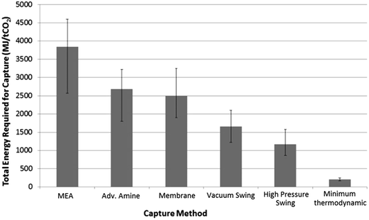 | ||
| Fig. 1 Comparison of calculated energy costs of different CO2 capture methods: MEA,16 advanced amine,17 membrane,18 vacuum swing.19 High pressure swing was calculated from the preliminary process model [see main text] and was found to be in agreement with literature values.20 Minimum thermodynamic separation costs were calculated from entropy of de-mixing. | ||
It must be noted that only total energy requirements are used as the basis of comparison in Fig. 1. From a cost perspective the differences between the value of thermal energy used by a temperature–swing system and the electrical energy used by a pressure–swing capture system may be quite large, especially in situations where surplus thermal energy is available. This would potentially narrow the gap between the two approaches.
In addition to pressurisation energy cost, the thermal performance of the sorbent must be taken into account in a pressure swing adsorber due to the temperature changes when adiabatic pressurisation occurs. While highly compressed gases can easily be shown to reach extreme temperatures, the use of rapid pressurisation and depressurisation cycles would allow for a pseudo steady-state scenario where the SoILs only reach moderate temperatures. Despite this, physisorption processes are typically particularly sensitive to changes in temperature due to the weak bonding interaction and hence the performance of these sorbents must also be tested at elevated temperatures.
As a relatively unexplored but potentially highly effective and efficient method for carbon dioxide capture, a selection of simple ammonium SoILs, anticipated to be low-cost, were synthesised and tested at a variety of scales with a specific focus on uptake kinetics and gas sorption selectivity. An imidazolium-IL and two PILs as well as their monomer forms were also tested for comparison. Where possible, the anion used was acetate, which has previously been shown to enable a high degree of CO2 solubility in RTILs and minimises cost by avoiding more complex anions such as PF6, BF4 and NTf2, which are typically used to promote low melting points.21 A preliminary computational simulation was carried out to determine interaction energies between the ILs and CO2. These showed that acetate was a good candidate anion as it gave a moderate binding energy with CO2, indicating reasonable selectivity but with low-energy regenerative desorption of the gas.
Experimental
Computer simulations were carried out on a Windows XP PC using Avogadro modelling software. The ion pairs of the ILs were constructed using the molecular editor and the geometry was optimised using firstly the Universal Force Field (UFF) and then the MMFF94s (Merck Molecular FF) force field to refine interaction potentials. A CO2 molecule was then constructed in the same modelling environment and the system was optimised using the MMFF94s FF which gave the intermolecular interaction energies and the distortion in the CO2 molecule. The global energy minimum was obtained by moving the CO2 molecule over the surface of the IL and then optimising at the appropriate location. From this the binding energy was obtained as well as the O–C–O dihedral angle. This was performed over a range of anions and cations in order to select suitable candidates for synthesis and evaluation. Calculation of the Single Point Energy (SPE) of the test complex was used in the calculation of the Binding Energy (BE). The BE is calculated using the sum of the SPEs of the tested ion and CO2 subtracted from the SPE of the complex, as shown in eqn (1).| ΔE = E([complex]) − (E([ion]) + E([CO2])) | (1) |
All amines, alkyl halide reagents, tetraethylammonium bromide (N2222 Br) and tetrabutylammonium bromide (N4444 Br) were purchased at the highest available purity from Sigma Aldrich and used without further purification. Amine quaternisation reactions were carried out using Schlenk-line techniques under an inert (N2) atmosphere unless otherwise indicated. Reactions using photosensitive reagents such as methyl iodide were carried out using aluminium foil protection on the exterior of the reaction vessel. All solvents were HPLC grade. CO2, N2 and argon were supplied by BOC-Linde.
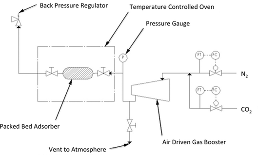
Small scale adsorption and densitometry studies were carried out using a Hiden Isochema IGA-0002 adsorption apparatus with a pressure range of 0–10 bar. Larger scale and higher pressure adsorption experiments were carried out using a bespoke packed-bed column constructed from Swagelok™ piping using a Jasco PU-1580-CO2 supercritical carbon dioxide pump, a Jasco BP-1580-81 back pressure regulator, an Omega PX409USB High Accuracy Pressure Transducer and an AND GF-1000 High Capacity 3 decimal place balance. 1H NMR spectra were recorded using a Bruker Avance 400 MHz spectrometer using tetramethyl silane as the internal standard.
General synthesis of halide SoILs
An oven-dried 2-neck 100 mL round bottom flask was charged with tertiary amine (2 mmol) dissolved in diethyl ether (25 mL) under an atmosphere of N2 using Schlenk-Line techniques. The appropriate alkyl halide (2.2 mmol) was then carefully added with rigorous stirring at room temperature for 16 hours. In all cases except with N1888 I, a white precipitate was observed to form over several hours. The range of cations used which yielded SoILs is shown in Fig. 2. Each sample was then evaporated to dryness using rotary evaporation before being washed three times with hexane to remove trace unreacted amine and alkyl halide. SoILs were then isolated in high yield as white crystalline solids. Before IGA analysis, the SoILs were ground to fine powders using a pestle and mortar and stored in a vacuum desiccator.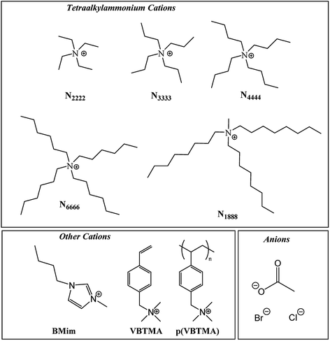 | ||
| Fig. 2 The selection of tetraalkylammonium, imidazolium and polymeric/monomeric compounds synthesised which yielded solid organic salts at room temperature. | ||
General procedure for synthesis of acetate SoILs
A 0.1 M aqueous solution of the appropriate tetraalkylammonium halide salt of the desired product was prepared, then slowly passed through a column of Amberlite™ IRN78 hydroxide form resin, which had been freshly-regenerated using 1 M high purity aqueous sodium hydroxide and then thoroughly washed to remove any sodium salts. After passing through the column, the resulting aqueous tetraalkylammonium hydroxide solution was immediately mixed with excess acetic acid. This was done to prevent decomposition of the ammonium hydroxide species, which are typically unstable. The product mixture was then tested for residual halide species by shaking a sample with aqueous silver nitrate. If no precipitate was observed, the sample was dried by rotary evaporation. Isopropanol and heptane were used sequentially to assist in the removal of water and excess acetic acid by azeotropic distillation. Isolated dry tetraalkylammonium acetate was then ground to a fine powder in a pestle and mortar and re-dried under high vacuum.General procedure for small scale testing on IGA-0002
A small SoIL or PIL sample (<100 mg) was loaded into the IGA sample chamber using a stainless steel mesh cup. The samples were re-dried to remove moisture from atmospheric exposure by sequential flow of dry nitrogen streams at 60 °C and high vacuum until no weight drop over time was observed. Samples were then evacuated to high vacuum for 4 hours and the dry mass was recorded. After first measuring sample density using argon as an inert gas, CO2 was introduced at a ramp rate of 180 mbar min−1. At each pressure interval, the CO2 pressure was maintained for a period of 50 minutes to equilibrate. This process was repeated for each point up to the maximum operating pressure of 10 bar. The sample was then evacuated to high vacuum for an additional 4 hours until the sample returned to its starting weight before the same pressure ramp profile was used with N2. Density data and raw uptake data were then used to apply a buoyancy correction proportional to the applied pressure under isothermal conditions, with the assumption of the adsorbed gas density equalling the density of the corresponding gas in liquid state.22 In cases where the mass of adsorbed gas was significantly less than the buoyancy effect of that gas at a given pressure, a simplified correction assuming zero gas adsorption was performed. The uptake results using this approximation were then used for recalculation of the buoyancy effect accounting for adsorbed gas density. This unavoidable approximation may marginally underestimate gas uptake, dependent on pressure, but will only apply when gas uptake is already very small.General procedure for high pressure testing
The pre-dried SoIL was tightly packed into a 7 cm, 12.7 mm diameter pipe with 0.5 g quartz wool wadding packed into either end. This is labelled in Fig. 3 as the packed adsorber. The sample was then re-dried under vacuum and heated nitrogen as in the small scale testing. The adsorber assembly, including both valves either side of the adsorber, was detached and then measured gravimetrically using a high capacity 3 decimal place balance. Changes in weight from gas adsorption were measured similarly. The void spacing within the adsorber column was calculated using idealised packing equations.23 This approach was validated by comparison with volumetric gas measurement using nitrogen on samples shown to have negligible nitrogen sorption capacity.Uptake rate results were measured using short exposure times limited by pressure transducer response rate and manual speed. Desorption rates were measured by on-balance depressurisation timed using a stopwatch.
Results and discussion
Computer modelling
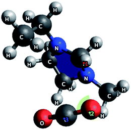
A number of anions and cations were investigated to determine their interactions with CO2. In the case of cations, the interaction was between the oxygen on the gas and the positive charge centre on the organic cation. Short intermolecular lengths were observed for ethylmethylimmidazolium ions (2.38 Å) and tetraalkylammonium ions (2.50 Å). The CO2 molecule occupied a geometry approximately orthogonal to the cation (shown in Fig. 4 for Emim+) exposing the C![[double bond, length as m-dash]](https://www.rsc.org/images/entities/char_e001.gif) O bond for interactions with the anion. Because the interaction is between the cation and the oxygen on CO2 there is no distortion of the molecule, suggesting that the cation does not promote CO2 activation but that it does stabilise the ion–gas complex. Similar studies showed one of the best anions to be acetate, with a binding energy for the IL to CO2 of approximately 150.5 kJ mol−1 and an O–C–O bond distortion of 5.4° for both ammonium and imidazolium salts.
O bond for interactions with the anion. Because the interaction is between the cation and the oxygen on CO2 there is no distortion of the molecule, suggesting that the cation does not promote CO2 activation but that it does stabilise the ion–gas complex. Similar studies showed one of the best anions to be acetate, with a binding energy for the IL to CO2 of approximately 150.5 kJ mol−1 and an O–C–O bond distortion of 5.4° for both ammonium and imidazolium salts.
This indicated that physisorption was the primary process as O–C–O bond angles approaching 120° (60° distortion) are expected for processes undergoing chemisorption. Therefore, it was decided to investigate tetraalkylammonium acetates as the primary target as they would be good candidates for physisorption studies and considerably cheaper than other anion–cation combinations. Some bromide derivatives were also prepared for comparison. These have weaker binding energies than the chlorides but also suffer from moisture instability.
CO2 adsorption by SoILs
As expected, the SoILs show somewhat lower CO2 uptake capacity than found with corresponding RTILs at similar pressures (Fig. 5 and 6).24 However, trends in uptake performance continued to follow previously-established trends in CO2 uptake shown by room temperature ionic liquids, such as the typically poorer performance of halide anion salts. This trend was reversed in the case of p(VBTMA) Cl, however, this can likely be attributed to differences in performance between PILs and monomeric SoILs, evidenced further by the differences in the uptake rate shown in later uptake experiments. Overall, it was shown that cations with longer chain lengths tended to show improved CO2 adsorption. However, the difference in uptake capacity between N1888 Ac and N6666 Ac could also indicate that while long alkyl chain lengths are beneficial for CO2 uptake, access to the quaternised nitrogen centre may also have a strong effect. Unfortunately, further exploration of any trends in tetraalkylammonium acetate SoILs with one short chain and three long chains was hindered by many other examples including N1666 Ac, N1444 Ac, N1333 Ac and N2666 Ac being found to be liquids at room temperature.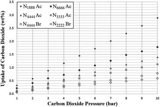 | ||
| Fig. 5 Adsorption of carbon dioxide by selected tetraalkylammonium solid ionic liquids (SoILs) at a pressure range of 1–10 bar, 298 K. Uptake is given as mass CO2 adsorbed per gram of sorbent. | ||
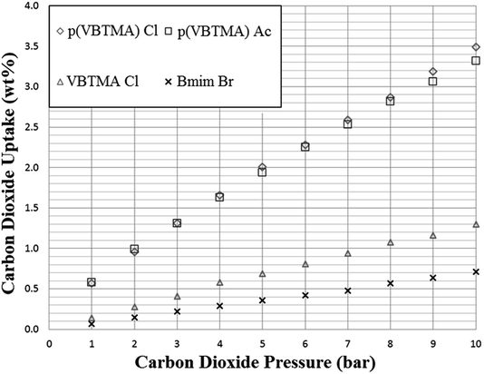 | ||
| Fig. 6 Adsorption of carbon dioxide by selected polymer and solid ionic liquids at a pressure range of 1–10 bar, 298 K. Uptake is given as mass CO2 adsorbed per gram of sorbent. | ||
Selectivity of SoILs for CO2 and N2 adsorption
As anticipated, adsorption of nitrogen was extremely low for all SoILs tested, with very small quantities adsorbed at higher pressures (see Fig. 7). Due to the near-zero uptake at low pressures and the low adsorption amounts, assumptions concerning the buoyancy correction had to be carried out. While, as mentioned in the experimental section, this is more likely to underestimate uptake than overestimate, with the buoyancy correction effect being 10 times larger than the measured uptake, it cannot be ruled out that the uptake observed is not an artifact of buoyancy correction, which might explain the quadratic shape of the uptake curves. In any event, as shown in Table 1, CO2:N2 selectivity for all ILs is very high and approximately in line with RTIL behaviour.4 It should be noted that for these measurements CO2 and nitrogen uptake were measured separately and not in competition.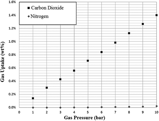 | ||
| Fig. 7 Example adsorption of nitrogen on N4444 Ac at 298 K. Uptake is given as mass CO2 adsorbed per gram of sorbent. | ||
| SoIL | Uptake of N2 at 10 bar, 298 K (wt%) | Uptake of CO2 at 10 bar, 298 K (wt%) | Selectivity for CO2 |
|---|---|---|---|
| N3333 Ac | 0.019 | 1.12 | 59![[thin space (1/6-em)]](https://www.rsc.org/images/entities/char_2009.gif) : :![[thin space (1/6-em)]](https://www.rsc.org/images/entities/char_2009.gif) 1 1 |
| N4444 Ac | 0.021 | 1.40 | 67![[thin space (1/6-em)]](https://www.rsc.org/images/entities/char_2009.gif) : :![[thin space (1/6-em)]](https://www.rsc.org/images/entities/char_2009.gif) 1 1 |
| N6666 Ac | 0.023 | 1.78 | 77![[thin space (1/6-em)]](https://www.rsc.org/images/entities/char_2009.gif) : :![[thin space (1/6-em)]](https://www.rsc.org/images/entities/char_2009.gif) 1 1 |
| N1888 Ac | 0.025 | 2.89 | 116![[thin space (1/6-em)]](https://www.rsc.org/images/entities/char_2009.gif) : :![[thin space (1/6-em)]](https://www.rsc.org/images/entities/char_2009.gif) 1 1 |
| N2222 Br | 0.011 | 0.59 | 53![[thin space (1/6-em)]](https://www.rsc.org/images/entities/char_2009.gif) : :![[thin space (1/6-em)]](https://www.rsc.org/images/entities/char_2009.gif) 1 1 |
| N4444 Br | 0.013 | 0.78 | 60![[thin space (1/6-em)]](https://www.rsc.org/images/entities/char_2009.gif) : :![[thin space (1/6-em)]](https://www.rsc.org/images/entities/char_2009.gif) 1 1 |
| Bmim Br | 0.013 | 0.71 | 54![[thin space (1/6-em)]](https://www.rsc.org/images/entities/char_2009.gif) : :![[thin space (1/6-em)]](https://www.rsc.org/images/entities/char_2009.gif) 1 1 |
| VBTMA Cl | 0.047 | 1.30 | 28![[thin space (1/6-em)]](https://www.rsc.org/images/entities/char_2009.gif) : :![[thin space (1/6-em)]](https://www.rsc.org/images/entities/char_2009.gif) 1 1 |
| p(VBTMA) Cl | 0.032 | 3.49 | 109![[thin space (1/6-em)]](https://www.rsc.org/images/entities/char_2009.gif) : :![[thin space (1/6-em)]](https://www.rsc.org/images/entities/char_2009.gif) 1 1 |
| p(VBTMA) Ac | 0.023 | 3.32 | 144![[thin space (1/6-em)]](https://www.rsc.org/images/entities/char_2009.gif) : :![[thin space (1/6-em)]](https://www.rsc.org/images/entities/char_2009.gif) 1 1 |
High pressure testing
A further selection of the SoILs were synthesised on a larger scale, to allow for testing at higher pressures and larger scales in the high pressure testing apparatus shown previously in Fig. 3. Sample sizes in each experiment were at least 2.5 g and the SoILs were chosen for availability and ease of synthesis and purification. Small discrepancies can be seen between the small-scale testing and those carried out in the larger adsorber when the same pressures are used. However, this is likely due to the slightly diminished gas–solid contact occurring within the solid-walled adsorber pipe compared to the stainless steel mesh container used within the IGA sample chamber. The results of these experiments showed that at elevated pressure, uptake results comparable with those previously reported using RTILs were achieved (see Fig. 8). For comparison, the maximum theoretical uptake of aqueous MEA in 30 wt% water is 10.8% when a stoichiometry of CO2![[thin space (1/6-em)]](https://www.rsc.org/images/entities/char_2009.gif) :
:![[thin space (1/6-em)]](https://www.rsc.org/images/entities/char_2009.gif) MEA of 1
MEA of 1![[thin space (1/6-em)]](https://www.rsc.org/images/entities/char_2009.gif) :
:![[thin space (1/6-em)]](https://www.rsc.org/images/entities/char_2009.gif) 2 is achieved. While this metric compares high pressure uptake using SoILs with atmospheric-pressure uptake of MEA, the possibility of MEA achieving higher uptakes at elevated pressures cannot be ruled out. However, in a working scenario, this approach would have to combine the high MEA temperature swing energy costs with further pressure swing energy costs.25–27
2 is achieved. While this metric compares high pressure uptake using SoILs with atmospheric-pressure uptake of MEA, the possibility of MEA achieving higher uptakes at elevated pressures cannot be ruled out. However, in a working scenario, this approach would have to combine the high MEA temperature swing energy costs with further pressure swing energy costs.25–27
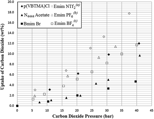 | ||
| Fig. 8 Results of higher pressure testing of selected ionic liquids from this work (solid markers) compared with literature results for common RTILs used for CO2 adsorption at 298 K (hollow markers). (a)Zhu,25(b)Peters,26(c)Lee27 Uptake is given as mass CO2 adsorbed per gram of sorbent. | ||
Other more direct comparisons may be made with solid sorbents such as activated carbon and zeolite 13X. Of these, activated carbon shows an uptake capacity of 48.6 wt% at 40 bar, and zeolite 13X shows 32.4 wt% at 32 bar. While compared to Fig. 8, both activated carbon and zeolite 13X have much higher CO2 uptake capacities at elevated pressures, CO2/N2 uptake selectivity is lower (3.9![[thin space (1/6-em)]](https://www.rsc.org/images/entities/char_2009.gif) :
:![[thin space (1/6-em)]](https://www.rsc.org/images/entities/char_2009.gif) 1 and 3.3
1 and 3.3![[thin space (1/6-em)]](https://www.rsc.org/images/entities/char_2009.gif) :
:![[thin space (1/6-em)]](https://www.rsc.org/images/entities/char_2009.gif) 1 respectively) by the same measurement as shown in Table 1. Additionally, it should be noted that a significant amount of CO2 remains bound to these sorbents at atmospheric pressure (9.8% and 28.7% respectively), which will either reduce efficiency when using pressure swing only, or mandate vacuum swing approaches, which again would add costs.28,29
1 respectively) by the same measurement as shown in Table 1. Additionally, it should be noted that a significant amount of CO2 remains bound to these sorbents at atmospheric pressure (9.8% and 28.7% respectively), which will either reduce efficiency when using pressure swing only, or mandate vacuum swing approaches, which again would add costs.28,29
Rate of CO2 uptake
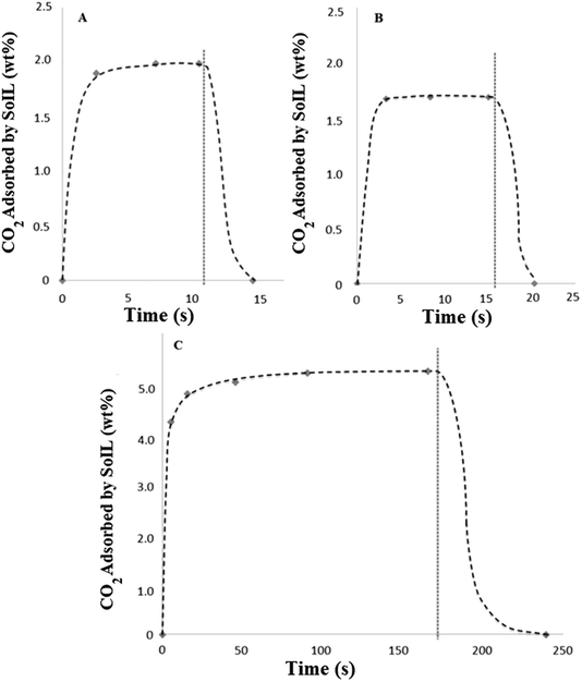
The nature of the high pressure testing apparatus allowed measurement of the rate of CO2 adsorption. This was achieved by over-pressurising the inlet CO2 pipeline (see Fig. 3) to a fixed pressure, which allowed it to act as a ballast vessel while the valve to the adsorber was closed. In this way, it was possible to pressurise the adsorber to a repeatable pressure and measure the isobaric rate of uptake in discrete, extremely short experiments. Desorption experiments were carried out by simple depressurisation to atmosphere during weighing.Due to the limitations of manually opening and closing the adsorber valves and the response times of the pressure gauge and balance, sample times shorter than 2 or 3 seconds were not possible. Results shown in Fig. 9 show the extremely rapid uptake and desorption achieved for both the tetra-alkylammonium and imidazolium SoILs. It should be noted that for both A and B a significant portion of the adsorb time will be limited by the motion of the gas itself and as such these represent an overestimation of maximum uptake times. Fig. 9A shows N4444 acetate reaching 94% capacity: no weight change is observed in experiments longer than 10 seconds, with maximum capacity reached after approximately 8 seconds. Following this, desorption back to the starting weight was completed within 4 seconds. In comparison, RTILs have been shown to take up to 5 hours to reach equilibrium, typically taking longer than 1 hour to reach 50% maximum capacity.30 Other solid sorbents such as activated carbon and 13X are swifter than RTILs, but still significantly slower than the SoILs with uptake rates of 1 minute to reach 50% of maximum capacity and 30 minutes to reach 100% for activated carbon.31 13X has a similar uptake rate performance, taking 50 seconds to 1 minute to achieve approximately 50% uptake and up to 100 minutes to reach full capacity.32
By taking the mass of CO2 adsorbed during the first 3 seconds of uptake and the desorb rate, it can then be calculated that the N4444 acetate, if cycled for 3 seconds of uptake followed by 4 seconds of desorb, could theoretically process a total of 129.4 g of CO2 per kilogram of sorbent per minute in pure CO2 at a pressure of 15 bar. While this measure does not take into account a wide range of factors, not least that the working partial pressure of CO2 of a real pressure swing capture system would be much lower, or any possible scaling effect, it usefully illustrates the potential benefits of fast sorbent cycling.
Fig. 9B shows Bmim bromide achieving even faster uptake, although at lower total capacity with the maximum capacity being reached in approximately 3.5 seconds. Once again desorption was complete in under 4 seconds. By applying the same calculation as that carried out for N4444 acetate, the combination of the higher density and lower uptake capacity of the Bmim bromide gives a maximum CO2 process rate of 98.5 g CO2 per kilogram sorbent per minute under the same conditions. This shows the poorer performance of the halide-based SoILs in comparison with their acetate counterparts.
Significantly slower uptake was observed using the polymeric ionic liquid sorbent p(VBTMA) chloride (Fig. 9C), requiring approximately 3 minutes to reach capacity. This compares well with previous literature results using PILs.30 While the total uptake capacity, as shown previously, is significantly higher, this slower rate of uptake dramatically decreases the maximum CO2 process rate to approximately 30.6 g CO2 per kilogram sorbent per minute, even when adsorb time is shortened to 16 seconds. This demonstrates that polymerisation of the ionic liquid, while offering significantly higher uptake capacities, decreases the rate at which the ionic liquid can be cycled, likely due to the slower permeation of the carbon dioxide polymer.
Effect of temperature
As discussed in the introduction, one factor that must be taken into account when examining pressure swing systems is the temperature of the compressed gas, which can easily be very high, even at only moderate pressures. Therefore, a final series of tests was carried out on the N4444 acetate SoIL, chosen for its high melting point (95–98 °C), to determine the effect of temperature on CO2 uptake at different pressures. While CO2 solubility in RTILs is extremely sensitive to gas temperature, the sensitivity of the SoILs to temperature was much subtler, with more pronounced drops in uptake capacity only occurring at both high temperatures and high pressures as shown in Fig. 10. While we were unable to carry out these experiments when both nitrogen and carbon dioxide were present to probe how this may affect selectivity, it can be suggested that as long as the SoILs do not melt, temperature may be no great obstacle to uptake capacity. This feature, if common across other SoILs, further underlines their observed robust nature, as seen in the prolonged experiments carried out to provide the data shown in Fig. 10 on a single sample which showed no detectable degradation despite the prolonged heating.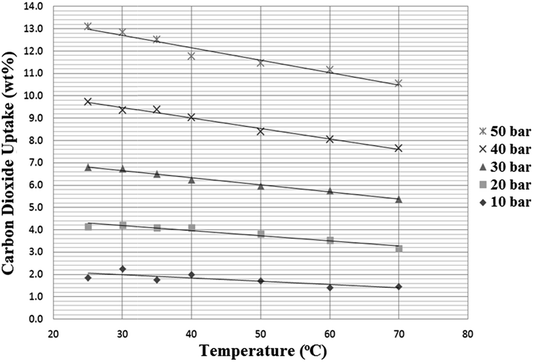 | ||
| Fig. 10 The effect of temperature on the CO2 uptake capacity of N4444 acetate at different pressures. | ||
Conclusions
In summary, a series of experiments were carried out to determine if the high degree of CO2 solubility and selectivity over N2 in Room Temperature Ionic Liquids (RTILs) for pressure swing carbon capture was replicated in finely-ground solid ionic liquids. From the results shown here, it can be shown that despite slightly diminished maximum uptake capacity for CO2, these Solid Ionic Liquids (SoILs) have great potential benefit as capture agents in pressure swing adsorption due to their extremely rapid uptake and desorb speeds, thousands or tens of thousands of times faster than RTILs. As a consequence, far less solid ionic sorbent would be required in a given process than the corresponding liquid sorbent system, helping to counteract the major perceived disadvantage to ionic liquids of high cost. Additional benefits would appear to include a high tolerance to elevated temperatures without significant loss of capture capacity and a very low rate of degradation under experimental conditions. We believe that this overlooked class of organic salt has great potential for further development, enabling low-cost carbon capture for climate change mitigation.Acknowledgements
We thank EPSRC for funding the 4CU Programme Grant (EP/K001329/1) at the University of Sheffield which has supported this work and GRMD, and for a DTA Studentship (DGR). We also thank EPSRC for funding of the CO2Chem Grand Challenge Network to PS (EP/K007947/1 & EP/H035702/1).Notes and references
- J. Gale, J. Bradshaw, Z. Chen, A. Garg, D. Gomez, H.-H. Rogner, D. Simbeck and R. Williams, IPCC Special Report on Carbon Dioxide Capture and Storage, Working Group III of the Intergovernmental Panel on Climate Change, Cambridge University Press, Cambridge, UK, 2005, ISBN-13 978-0-521-86643-9 Search PubMed.
- L. B. Gregory and W. G. Scharmann, Ind. Eng. Chem., 1937, 29, 514–519 CrossRef CAS.
- G. Gouedard, D. Picq, F. Launay and P.-L. Carrette, Int. J. Greenhouse Gas Control, 2012, 10, 244–270 CrossRef.
- J. L. Anthony, J. L. Anderson and E. J. Maginn, J. Phys. Chem. B, 2005, 109, 6366–6374 CrossRef CAS PubMed.
- C. Maton, N. De Vos and C. V. Stevens, Chem. Soc. Rev., 2013, 42, 5963–5977 RSC.
- Aqueous MEA diffusion coefficient: M. S. Jassim, G. Rochelle, D. Eimer and C. Ramshaw, Ind. Eng. Chem. Res., 2007, 46, 2823–2833 CrossRef CAS Example ionic liquid diffusion coefficients: C. Moya, J. Palomar, M. Gonzales-Miquel, J. Bedia and F. Rodriguez, Ind. Eng. Chem. Res., 2014, 53, 13782–13789 CrossRef.
- Example of MEA-IL mixture for capture: J. Yang, X. Yu, J. Yan and S.-T. Tu, Ind. Eng. Chem. Res., 2014, 53, 2790–2799 CrossRef CAS Example of MeOH-IL mixture for capture: C. Dai, W. Wei, Z. Lei, C. Li and B. Chen, Fluid Phase Equilib., 2015, 391, 9–17 CrossRef.
- N. Markusson and S. Haszeldine, Energy Policy, 2010, 38, 6695–6702 CrossRef.
- D. Cameron, Hansard, HC Deb, December 16 2015, vol. 603, col 1548.
- J. S. Wilkes, P. Wasserscheid and T. Welton, Ionic Liquids in Synthesis, ed. P. Wasserscheid and T. Welton, Wiley-VCH, Weinheim, Germany, 2nd edn, 2002, ch. 1, pp. 1–6 Search PubMed.
- J. Tang, Y. Shen, M. Radosz and W. Sun, Ind. Eng. Chem. Res., 2009, 48, 9113–9118 CrossRef CAS; J. Tang, W. Sun, H. Tang, M. Radosz and Y. Shen, Macromolecules, 2005, 38, 2037–2039 CrossRef.
- J. M. Plaza, D. Van Wagener and G. T. Rochelle, Int. J. Greenhouse Gas Control, 2010, 4, 161–166 CrossRef CAS.
- R. Gross, P. Heptonstall, M. Leach, J. Skea, D. Anderson and T. Green, Renewable Electricity and the Grid: The Challenge of Variability, ed. G. Boyle, Cromwell Press, Trowbridge, UK, 2007, ch. 4, pp. 73–95 Search PubMed.
- T. Nittaya, P. L. Douglas, E. Croiset and L. A. Ricardez-Sandoval, Fuel, 2014, 116, 672–691 CrossRef CAS.
- O. M. Moen and H. S. Stene, Power Plant with CO2 Capture Based on PSA Cycle, Norwegian University of Science and Technology, Trondheim, Norway, 2014 Search PubMed.
- MEA capture energy figures taken from: T. Harkin, A. Hoadley and B. Hooper, Energy Proc., 2009, 1, 3817–3825 CrossRef CAS; L. M. Romeo, I. Bolea and J. M. Escosa, Appl. Therm. Eng., 2008, 28, 1039–1046 CrossRef; Y. Yang and R. Zhai, Paths to Sustainable Energy, J. Nathwani and A. Ng, InTech, Rijeka, Croatia, 2010, ch. 24, pp. 499–510 CrossRef; U. Desideri and A. Paolucci, Energy Convers. Manage., 1999, 40, 1899–1915 CrossRef.
- Advanced amine capture figures estimated from existing figures given by: S. Wong and R. Bioletti, Carbon Dioxide Separation Technologies, Carbon & Energy Management, Alberta, Canada, 2002 Search PubMed; M. Rameshni, Carbon Capture Overview, Worley Parsons Resources & Energy, Monrovia, CA, USA, 2010, calculated as 30% reduction in energy usage with advanced amines compared to MEA Search PubMed.
- Membrane CO2 separation energy figures taken from: P. K. Kundu, A. Chakma and X. Feng, Int. J. Greenhouse Gas Control, 2014, 28, 248–256 CrossRef CAS; B. Belaissaoui, G. Cabot, M.-S. Cabot, D. Willson and E. Favre, Chem. Eng. Sci., 2013, 97, 256–263 CrossRef; B. Belaissaoui, D. Willson and E. Favre, Chem. Eng. J., 2012, 211–212, 122–132 CrossRef.
- Vacuum pressure swing separation energy figures taken from: J. Zhang, P. A. Webley and P. Xiao, Energy Convers. Manage., 2008, 49, 346–356 CrossRef CAS; S. Krishnamurth, V. R. Rao, S. Guntuka, P. Sharratt, R. Haghpanah, A. Rajendran, M. Amanullah, I. A. Karimi and S. Farooq, AIChE J., 2014, 60, 1830–1842 CrossRef; L. Liu, T. Du, X. Fang, S. Che and W. Tan, The 26th Chinese Control and Decision Conference, IEEE, USA, 2014, pp. 4038–4041 Search PubMed.
- High pressure swing energy costs calculated in hybrid thermal/high pressure and vacuum/high pressure systems in line with model predictions: Y. Xie, Y. Zhang, X. Lu and X. Ji, Appl. Energy, 2014, 136, 325–335 CrossRef CAS; O. M. Moen and H. S. Stene, Power Plant with CO2 Capture Based on PSA Cycle, NTNU Trondheim, Norway, 2014 Search PubMed.
- J. Albo, T. Yoshioka and T. Tsuru, Sep. Purif. Technol., 2014, 122, 440–448 CrossRef CAS.
- K. Murata, M. El-Merraoui and K. Kaneko, J. Chem. Phys., 2001, 114, 4196–4205 CrossRef CAS.
- H. E. White and S. F. Walton, J. Am. Ceram. Soc., 1937, 20, 155–166 CrossRef CAS.
- Y. Xie, Y. Zhang, X. Lu and X. Ji, Appl. Energy, 2014, 136, 325–335 CrossRef CAS.
- Z. Lei, J. Yuan and J. Zhu, J. Chem. Eng. Data, 2010, 55, 4190–4194 CrossRef CAS.
- A. Shariati, K. Gutkowski and C. J. Peters, AIChE J., 2005, 51, 1532–1540 CrossRef CAS.
- D.-J. Oh and B.-C. Lee, Korean J. Chem. Eng., 2006, 23, 800–805 CrossRef CAS.
- F. Dreisbach, R. Staudt and J. U. Keller, Adsorption, 1999, 5, 215–227 CrossRef CAS.
- S. Cavenati, C. A. Grande and A. E. Rodrigues, J. Chem. Eng. Data, 2004, 49, 1095–1101 CrossRef CAS.
- J. Tang, H. Tang, W. Sun and M. Radosz, Polymer, 2005, 46, 12460–12567 CrossRef CAS.
- E. S. Kikkinides and R. T. Yang, Ind. Eng. Chem. Res., 1993, 32, 2714–2720 CrossRef CAS.
- D. Ko, R. Siriwardane and L. T. Biegler, Ind. Eng. Chem. Res., 2003, 42, 339–348 CrossRef CAS; Z. Zhang, W. Zhang, X. Chen, Q. Xia and Z. Li, Separ. Sci. Technol., 2010, 45, 710–719 CrossRef.
| This journal is © The Royal Society of Chemistry 2016 |

