 Open Access Article
Importance of many-body orientational correlations in the physical description of liquids
Hajime
Tanaka
*
Institute of Industrial Science, University of Tokyo, 4-6-1 Komaba, Meguro-ku, Tokyo 106, Japan. E-mail: tanaka@iis.u-tokyo.ac.jp; Fax: +81-3-5452-6126; Tel: +81-3-5452-6125
First published on 31st October 2013
Abstract
Liquids are often assumed to be homogeneous and isotropic at any lengthscale and translationally invariant. The standard liquid-state theory is constructed on the basis of this picture and thus basically described in terms of the two-body density correlation. This picture is certainly valid at rather high temperatures, where a liquid is in a highly disordered state. However, it may not necessarily be valid at low temperatures or for a system which has strong directional bonding. Indeed, there remain fundamental unsolved problems in liquid science, which are difficult to explain by such a theory. They include water's thermodynamic and kinetic anomalies, liquid–liquid transitions, liquid–glass transitions, and liquid–solid transitions. We argue that for the physical description of these phenomena it is crucial to take into account many-body (orientational) correlations, which have been overlooked in the conventional liquid-state theory. It is essential to recognise that a liquid can lower its free energy by local or mesoscopic ordering without breaking global symmetry. Since such ordering must involve at least a central particle and its neighbours, which are more than two particles, it is intrinsically a consequence of many-body correlations. Particularly important ordering is associated with local breakdown of rotational symmetry, i.e., bond orientational ordering. We emphasize that translational ordering is global whereas orientational ordering can be local. Because of the strong first-order nature of translational ordering, its growth in a liquid state is modest. Thus any structural ordering in a liquid should be associated primarily with orientational ordering and not with translational ordering. We show that bond orientational ordering indeed plays a significant role in all the above-mentioned phenomena at least for (quasi-)single-component liquids. In this Introductory Lecture, we discuss how these phenomena can be explained by such local or mesoscopic ordering in a unified manner.
1 Introduction
Liquid is one of the most fundamental states of matter, and has unique transport properties, which are absent in the other forms of matter.1,2 Despite its importance, however, the physical understanding of liquids is very difficult because of its disordered nature (or, the lack of periodicity) and complex many-body interactions due to the high density. As a result, there remain fundamental unsolved problems concerning the basic properties of liquids. They include water's thermodynamic and kinetic anomalies,3–6 liquid–liquid transitions,7,8 liquid–glass transitions,9–14 liquid–solid transitions,15 liquid structure near interfaces, and structure around solutes and in mixtures,16 which are the main topics of this Faraday Discussion.The standard liquid-state theory has been constructed on the assumption that liquids have homogeneous, isotropic, and random structures. The most relevant order parameter for the description of a liquid state is the density field ρ(![[r with combining right harpoon above (vector)]](https://www.rsc.org/images/entities/i_char_0072_20d1.gif) ) and its two-body correlation has been believed to be able to characterize the state of liquid and control its static and dynamic properties. This is of course valid in the first approximation and the theory is successful in describing the basic properties of liquids.1,2 However, to understand the above-mentioned phenomena, we need to go beyond this level of description and explicitly take many-body correlations into account. To do so, we should first recognise that there are two fundamental symmetries to be broken upon ordering: one is translational symmetry and the other is rotational symmetry. The two-body density correlator basically describes how translational order decays spatially. Crystallization accompanies the breakdown of translational symmetry. In two dimensions (2D), there are sequential breakdown of symmetries upon densification: breakdown of rotational symmetry followed by that of translational symmetry.17 In three dimensions (3D), on the other hand, crystallization has been believed to take place by one step, accompanying the simultaneous breakdown of translational and rotational symmetry. Note that the breakdown of translational symmetry automatically leads to that of rotational symmetry. Here we emphasise that the breakdown of translational symmetry is intrinsically global, but that of rotational symmetry can be local: rotational symmetry can be broken locally before translational symmetry is broken globally. This is a very important point when we consider local or mesoscopic ordering in liquids that preserve global translational invariance.
) and its two-body correlation has been believed to be able to characterize the state of liquid and control its static and dynamic properties. This is of course valid in the first approximation and the theory is successful in describing the basic properties of liquids.1,2 However, to understand the above-mentioned phenomena, we need to go beyond this level of description and explicitly take many-body correlations into account. To do so, we should first recognise that there are two fundamental symmetries to be broken upon ordering: one is translational symmetry and the other is rotational symmetry. The two-body density correlator basically describes how translational order decays spatially. Crystallization accompanies the breakdown of translational symmetry. In two dimensions (2D), there are sequential breakdown of symmetries upon densification: breakdown of rotational symmetry followed by that of translational symmetry.17 In three dimensions (3D), on the other hand, crystallization has been believed to take place by one step, accompanying the simultaneous breakdown of translational and rotational symmetry. Note that the breakdown of translational symmetry automatically leads to that of rotational symmetry. Here we emphasise that the breakdown of translational symmetry is intrinsically global, but that of rotational symmetry can be local: rotational symmetry can be broken locally before translational symmetry is broken globally. This is a very important point when we consider local or mesoscopic ordering in liquids that preserve global translational invariance.
We argue that any liquids tend to form locally favoured structures, which locally have a lower free energy and a longer lifetime than disordered normal-liquid structures (see Fig. 1). On the basis of this picture, we proposed that the key to solving the long-standing problems in liquid physics is the recognition of the importance of spontaneous breakdown of local or mesoscopic rotational symmetry and thus we need a bond orientational order parameter in addition to density for the physical description of liquids.18,19 We used this two-order-parameter model to explain water's anomalies,20–24 liquid–liquid transitions,18,25 liquid–glass transitions,19,26–32 and liquid–solid transitions.33,34 We also recently discussed a possible unified description of all these phenomena.35 Here we review the current situation of our understanding of liquids and competing views on the phenomena mentioned above.
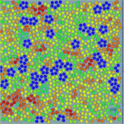 | ||
| Fig. 1 An example of local bond orientational ordering in a liquid. Here blue pentagons are locally favoured structures spontaneously formed in a sea of normal liquid structures (particles with the other colours). They have finite lifetime and thus are transient. This is obtained by molecular dynamics simulations of spherical particles interacting with a special anisotropic potential, which we call two-dimensional (2D) spin liquid.36 | ||
The organization of this paper is as follows. In section 2, we discuss the origins of mesoscopic ordering in liquids. In section 3, we describe a phenomenological theory, which can capture this feature. In sections 4–7, we discuss water's anomalies, liquid–liquid transitions, liquid–glass transitions, and liquid–crystal transitions, respectively. In section 8, we summarize our paper.
2 Local or mesoscopic ordering in liquids
A system always tends to lower its free energy. Local ordering in liquids is also induced to lower the free energy locally. There can be two cases for local ordering: entropy-driven and energy-driven ordering. Here we discuss each case by using typical examples, although in reality there are always both contributions.2.1 Entropy-driven local ordering
First we consider entropy-driven local ordering. This is particularly important in hard spheres, whose free energy is purely entropic. The entropy of hard spheres is basically composed of the configurational and correlational (or vibrational) part.37 For example, the crystallization of hard spheres is a consequence of gaining the correlational entropy at the expense of the configurational one, which results in the reduction of the total free energy. Local ordering in hard spheres is a result of dense packing. A system locally tends to form arrangements that can be most densely packed upon compression since such configurations provide large free volumes for vibrational motions in the uncompressed natural state (see Fig. 2). For hard spheres of almost equal sizes, there are three key structures that minimize the local volume: face-centred cubic (fcc), hexagonal close packing (hcp), and icosahedral (ico) structures (see Fig. 3). Thus, these are three relevant locally favoured structures for weakly polydisperse hard spheres. Despite the ability of the structures to be compacted, these structures occupy the same volume as disordered structures in a liquid state. This feature allows the increase of the local correlational (or vibrational) entropy, which is the reason why such structures are favoured. Accordingly, even if locally favoured structures are formed, the density is basically homogeneous in the system and density fluctuations is simply determined by the isothermal compressibility KT. This is a consequence of the fact that bond orientational ordering in hard spheres is completely decoupled from translational ordering. This is characteristic of entropy-driven local order. | ||
| Fig. 2 Schematic figure explaining the relation between bond orientational ordering and translational ordering. A structure having only bond orientational order has a room of a similar amount of thermal fluctuations (or, free volume) for each particle and thus it reduces the correlational entropy at the expense of the orientational configurational entropy. This situation is favoured in an intermediate density region where the density is high enough for a completely random state not to be favoured but low enough for the reduction of the configurational entropy associated with translational ordering not to take place. Without bond orientational order, the free volume for each particle fluctuates too largely, which leads to the loss of correlational entropy at this density regime. Upon its densification, translational order is automatically gained, if the size polydispersity is not so large. However, this happens only for a spatial region where pre-existing bond orientational order has a phase coherency. This mechanism is crucial when we consider crystal nucleation (see section 7). | ||
 | ||
| Fig. 3 Schematic figure representing the densely packed structures made of 13 spherical particles, which have fcc, hcp, and icosahedral configurations. (a) fcc, (b) hcp, and (c) icosahedron. This figure is reproduced from Fig. 36 of ref. 35. | ||
Here it is worth mentioning the important relation between local rotational symmetry and spatial extendability of locally favoured structures. Among fcc, hcp and ico structures, fcc and hcp are spatially extendable and can grow its size, whereas ico is not extendable and cannot grow its size. This means that fcc and hcp bond orientational order can be mesoscopic, but ico must be localised, which leads to the essential difference in the nature between them. To what extent fcc or hcp bond orientational order grows is again determined by the competition of the two types of entropy: their growth leads to the loss of the configurational entropy of locally favoured structures and the gain of the correlational entropy coming from the reduction of the free energy associated with the spatial gradient of the order parameter. Frustration is another source disturbing their growth.
2.2 Energy-driven local ordering
In many realistic liquids, locally favoured structures are formed to gain the local energy at the expense of configurational and vibrational entropy. The interaction can be isotropic or anisotropic. A simple isotropic attractive potential leads to locally favoured structures with dense packing, such as fcc, hcp, and ico structures, whereas an anisotropic directional potential can lead to various symmetry depending upon the local symmetry favoured by the potential. In water-type liquids such as water, Si, and Ge, tetrahedral order is locally favoured by hydrogen or covalent bonding. For a 2D spin liquid shown in Fig. 1, pentagons are locally favoured, although antiferromagnetic order is favoured at a longer lengthscale36 (see Fig. 4).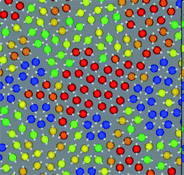 | ||
| Fig. 4 A snapshot of 2D spin liquid in a supercooled state. Red particles have crystal-like bond orientational ordering (more specifically, antiferromagnetic order), which plays a crucial role in glass transition and crystallization, whereas blue particles are locally favoured structures with pentagonal symmetry, which plays a primary role in water-type anomalies and liquid–liquid transitions. The latter also plays an important role in vitrification if it competes with crystallization, which is linked to the above bond orientational ordering (appeared red). A spin on a particle is also shown by an white arrow in this figure. | ||
In this energy-driven “local” ordering, bond orientational ordering usually accompanies the change in the local density, unlike the above entropy-driven ordering. In other words, there is a non-trivial coupling of bond orientational ordering with translational ordering. For example, both hydrogen and covalent bonding favours not only a particular orientation, but also a particular distance between molecules or atoms. Furthermore, the angular constraint between bonds formed by anisotropic interactions can inevitably lead to such a coupling. The formation of a void in the middle of a pentagon formed in 2D spin liquids is such an example (see Fig. 1). In general, thus, locally favoured structures can have specific volumes different from normal-liquid structures. This feature plays a key role in water's anomalies, as will be shown below.
The relationship between local rotational symmetry and spatial extendability of locally favoured structures is the same as in the case of entropy-driven local ordering. For example, in 2D spin liquids, pentagons are non-extendable local structures, whereas antiferromagnetic order is extendable mesoscopic order (see Fig. 4). We note that unlike locally favoured structures mesoscopic ordering does not accompany a density change since translational ordering must be involved to increase the density at such a mesoscopic lengthscale but it never happens in a liquid state.
2.3 How to express local or mesoscopic ordering mathematically
Local or mesoscopic ordering described above is not easy to express by the density field due to its intrinsically many-body nature. Here we use so-called bond orientational order parameter, which can be expressed by the distribution of bonds joining a particle located at![[r with combining right harpoon above (vector)]](https://www.rsc.org/images/entities/i_char_0072_20d1.gif) to its nearest neighbours.17 Expanding the density ρ(
to its nearest neighbours.17 Expanding the density ρ(![[r with combining right harpoon above (vector)]](https://www.rsc.org/images/entities/i_char_0072_20d1.gif) ,ω) of points pierced by these bonds on a small sphere inscribed about
,ω) of points pierced by these bonds on a small sphere inscribed about ![[r with combining right harpoon above (vector)]](https://www.rsc.org/images/entities/i_char_0072_20d1.gif) , we have17,38,39
, we have17,38,39 | (1) |
We take the normalized average of qlm over a small volume located at ![[r with combining right harpoon above (vector)]](https://www.rsc.org/images/entities/i_char_0072_20d1.gif) , which we express by
, which we express by ![[q with combining macron]](https://www.rsc.org/images/entities/i_char_0071_0304.gif) lm(
lm(![[r with combining right harpoon above (vector)]](https://www.rsc.org/images/entities/i_char_0072_20d1.gif) ). Then, its rotationally invariant combination can be defined as
). Then, its rotationally invariant combination can be defined as
 | (2) |
In the case of water, ψjk is the angle formed by the lines joining the oxygen atom of a given water molecule and those of its nearest neighbours j and k.
Here we also define other quantities characterizing bond orientational order.
 | (3) |
Following ref. 41 we also use the tensorial bond orientational order parameter coarse-grained over the neighbours:
 | (4) |
3 Phenomenological two-order-parameter model incorporating local and mesoscopic ordering in a liquid
As discussed above, to express local or mesoscopc ordering in a liquid, we need bond orientational order parameters in addition to the density field. Although we may need more than two bond orientational parameters, we mainly consider the simplest situation that a liquid state is described by two order parameters, density and one bond orientational order parameter.3.1 Free energy associated with the formation of locally favoured structures
In general, there can be two types of bond orientational orderings, one of which is associated with local structural ordering and the other with medium-range crystal-like bond orientational order (see Fig. 4). We note that each of them may need more than two bond orientational order parameters to specify it (such as Ql, Ql′, Wm, Wm′,…). Here, focusing only on local structural ordering, we express a liquid state by a simple two-state model with cooperativity of such ordering (see Fig. 5). The first two-state model of liquid–liquid transition (LLT) was developed by Strässler and Kittel.47 Rapoport48 used it to explain melting-curve maxima of atomic liquids, such as carbon, at high pressure. Aptekar49 explained the metal–non-metal transition in germanium and silicon by a two-state model. Some time ago, we generalized this basic idea by introducing the bond order parameter(s) in addition to the density order parameter, and proposed the two- (or multi-) order-parameter model of liquid to explain not only LLT, but also water-like anomalies, liquid–glass transitions and crystallization in a unified manner. Below we present a general framework of our model of liquid to describe these phenomena. We also show how these phenomena, which are apparently independent of each other, can be closely related to each other.35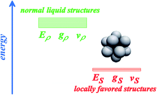 | ||
| Fig. 5 A two-state model for a liquid: one is normal-liquid structures (energy Eρ, degeneracy gρ, and specific volume vρ) and the other is locally favoured structures (energy ES, degeneracy gS, and specific volume vS). For some liquids, there may be more than two distinct energy states. | ||
Here we focus on short-range bond orientational ordering, or the formation of locally favoured structures. Our model19,21–25 relies on a physical picture (see Fig. 1) that (i) there exist distinct locally favoured structures in a liquid and (ii) such structures are formed in a sea of normal liquid structures and its fraction S increases upon cooling since they are energetically (entropically for hard spheres) more favourable by ΔE than normal liquid structures: ΔE = Eρ–ES (see Fig. 5), where Ei is the energy of state i (i = ρ or S). Here normal liquid structures simply mean the background normal liquid structures. The specific volume and the entropy are larger and smaller for the former than for the latter, respectively, by Δv = vS − vρ and Δσ = kB ln(gρ/gS). Here vi and gi are, respectively, the specific volume and the degree of the degeneracy of state i (i = ρ or S). Δv can be either positive or negative depending upon a system, whereas Δσ is positive except for purely repulsive systems such as a hard-sphere liquid, where the gain of correlational entropy is the driving force of local structural ordering. We identify locally favoured structures as a minimum structural unit (symmetry element). It is associated with tetrahedral order for water-type liquids, whereas icosahedron for metallic liquids28,29,50,51 and hard spheres.44,52–54 To express such short-range bond ordering in liquids, we introduce the so-called bond orientational order parameter Qlm.
When locally favoured structures are distinct, there should be a clear threshold value separating the two states. For example, the fraction of blue pentagons is the bond order parameter S in Fig. 1. Then we can use the fraction of atoms (or particles) having ql(![[r with combining right harpoon above (vector)]](https://www.rsc.org/images/entities/i_char_0072_20d1.gif) ) higher than a certain threshold value as the local bond order parameter S (note that S is “not” entropy and instead σ represents entropy throughout this paper). When thermal fluctuation effects make locally favoured structures obscure, we need to decompose the distribution function of the order parameter into two (Gaussian) populations to estimate S.
) higher than a certain threshold value as the local bond order parameter S (note that S is “not” entropy and instead σ represents entropy throughout this paper). When thermal fluctuation effects make locally favoured structures obscure, we need to decompose the distribution function of the order parameter into two (Gaussian) populations to estimate S.
As can be seen above, both the scalar density field ρ and the tensorial bond orientational order Q stem from the angle-dependent density field ρ(![[r with combining right harpoon above (vector)]](https://www.rsc.org/images/entities/i_char_0072_20d1.gif) ,Ω). Although Q is tensorial, the fraction of locally favoured structures, S, is linked to the rotationally invariant scalar order parameter calculated from it. As a function of this scalar order parameter S, the phenomenological liquid-state free energy functional associated with locally favoured structures is given by19,21–25
,Ω). Although Q is tensorial, the fraction of locally favoured structures, S, is linked to the rotationally invariant scalar order parameter calculated from it. As a function of this scalar order parameter S, the phenomenological liquid-state free energy functional associated with locally favoured structures is given by19,21–25
 | (5) |
3.2 Free energy associated with density and tensorial bond orientational ordering
 | (6) |
A form of the Landau-type free energy associated with tensorial bond orientational ordering with translational and rotational invariance can be found, e.g., in ref. 63, 65, 66. For simplicity (see also a speculative explanation below), we consider the following free energy form associated with (scalar-like) bond orientational ordering Q:
![[t with combining tilde]](https://www.rsc.org/images/entities/i_char_0074_0303.gif) is the reduced temperature
is the reduced temperature ![[t with combining tilde]](https://www.rsc.org/images/entities/i_char_0074_0303.gif) = 1/ϕ − 1/ϕ0b (or
= 1/ϕ − 1/ϕ0b (or ![[t with combining tilde]](https://www.rsc.org/images/entities/i_char_0074_0303.gif) = T − T0b), and ⋯ represents frustration originating from competing bond orientational orderings (e.g., QCRYvs.QLFS), internal frustration (this is the case for icosahedral order38), and/or random disorder effects. Here QCRY is compatible with the symmetry of the equilibrium crystal (e.g., fcc and hcp order), whereas QLFS with incompatible to it (e.g., icosahedral order). Here ϕ0b (or T0b) is the bare transition volume fraction (or temperature). Even though the third order invariant I3 is suggestive of the first order nature of the transition, the transition might be almost continuous.
= T − T0b), and ⋯ represents frustration originating from competing bond orientational orderings (e.g., QCRYvs.QLFS), internal frustration (this is the case for icosahedral order38), and/or random disorder effects. Here QCRY is compatible with the symmetry of the equilibrium crystal (e.g., fcc and hcp order), whereas QLFS with incompatible to it (e.g., icosahedral order). Here ϕ0b (or T0b) is the bare transition volume fraction (or temperature). Even though the third order invariant I3 is suggestive of the first order nature of the transition, the transition might be almost continuous.
Frustration effects originating from competing QCRY and QLFS orderings and/or random disorder effects, e.g., due to polydispersity may change the nature of the transition from a continuous (characteristic to a tensorial order parameter) to a discrete Ising symmetry (characteristic to a scalar order parameter).67 We speculate that renormalization of frustration effects changes the symmetry of the transition from the continuous to the discrete Ising symmetry and also shifts the critical point from ϕ0b (or T0b) to ϕ0 (or T0), although this should be carefully checked. In relation to this, we note that such transformation of the phase ordering from (Heisenberg-type) continuous to (Ising (Z2)) discrete symmetry due to frustration and random disorder effects has also been known for spin systems,68,69 implying the generality of frustration and random disorder effects on the nature of the ordering. We also emphasize that frustration effects may not only change the type of ordering, but also lead to exotic critical phenomena accompanying the growing activation energy towards the hypothetical critical point. We note that the Ising nature of the glass transition has also been recently discussed on the basis of a two-state cluster picture by Langer.70,71
3.3 Coupling between density and bond orientational ordering
Now we consider couplings between orderings of ρ and Q, whose nature is very important in the following discussion. The lowest order coupling between Q and ρ should be given by the rotationally and translationally invariant energy:38,63 | (7) |
Up to the lowest order, ρ is not coupled linearly to Q, and ρ(![[q with combining right harpoon above (vector)]](https://www.rsc.org/images/entities/i_char_0071_20d1.gif) )ρ(−
)ρ(−![[q with combining right harpoon above (vector)]](https://www.rsc.org/images/entities/i_char_0071_20d1.gif) ) is coupled to it. Accordingly, the equilibrium ρ need not have the symmetry of the equilibrium Q. This particular type of coupling leads to an asymmetric coupling between the orderings. If the translational ordering temperature Tρ is higher than the bond orientational ordering temperature TQ then, because the Q–ρ interaction is linear in Q, the ordering of ρ at Tρ will necessarily induce an ordering in Q. This seems to justify the theory based on the density field alone, but which may not be the case as we will see later. On the other hand, if TQ > Tρ then, because the Q–ρ interaction is quadratic in ρ, the ordering of Q at TQ will have the effect of renormalizing the quadratic coupling without necessarily inducing an ordering of ρ. Jaríc proposed that this case of TQ > Tρ should correspond to quasicrystal formation.63
) is coupled to it. Accordingly, the equilibrium ρ need not have the symmetry of the equilibrium Q. This particular type of coupling leads to an asymmetric coupling between the orderings. If the translational ordering temperature Tρ is higher than the bond orientational ordering temperature TQ then, because the Q–ρ interaction is linear in Q, the ordering of ρ at Tρ will necessarily induce an ordering in Q. This seems to justify the theory based on the density field alone, but which may not be the case as we will see later. On the other hand, if TQ > Tρ then, because the Q–ρ interaction is quadratic in ρ, the ordering of Q at TQ will have the effect of renormalizing the quadratic coupling without necessarily inducing an ordering of ρ. Jaríc proposed that this case of TQ > Tρ should correspond to quasicrystal formation.63
Here we see the relevance of this form of coupling by looking at the two-dimensional probability distribution of density ρ and bond orientational order Q6, for a metastable fluid state of hard spheres at pressure βpσ3 = 17 (before the appearance of the critical nucleus) (see Fig. 6).72 The probability distribution is related to the Landau free energy, F(Q6,ρ) = −kBT logP(Q6,ρ). The free energy can be well fitted with a full cubic polynomial, for which the most important term is of the form Q6ρ2. This term is responsible for the shape of contours lines (black dashed line in Fig. 6): because the interaction is linear in Q6 and quadratic in ρ, the system can increase its orientational order without an increase of its translational order, but the opposite is not true, and an increase in density inevitably accompanies an increase in the average Q6. This is fully consistent with the above form of coupling. Note also that a small linear coupling between Q6 and ρ exists at high Q6, which can be seen in the small slope of the steepest descent path (white dashed arrow) in Fig. 6.
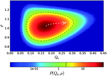 | ||
| Fig. 6 Probability distribution for a supercooled state of hard spheres in the ρ − Q6 space. The dashed black line is a contour line. The dashed white arrow is a steepest descent path from the maximum to a high Q6 point of the probability distribution function. This figure is reproduced from Fig. 2 of ref. 72. | ||
3.4 Total free energy of a system describing crystallization and vitrification
The total free energy Ftotal may then be given by the sum of translational ordering, local and global orientational ordering, and the couplings between them:| Ftotal = Fρ + FS + FQ + Fint. | (8) |
In the above, however, we need to take special care to avoiding double counting. This may be done with a proper projection procedure.
3.5 Free energy responsible for water's anomailes, liquid–liquid transitions, liquid–glass transitions, and liquid–solid transitions
In the above we discuss the free energy, mainly focusing on the roles of bond orientational ordering. Here we note that there are new important effects of bond orientational ordering, which have so far been overlooked in the physical description of liquids: (1) thermodynamic effects of short-range bond ordering (a scalar order parameter linked to QLFS), which can be considered on the basis of the simpler free energy FS (see eqn (5)), (2) random field effects of QLFS on crystallization (long-range translational ρ(r) and bond orientational ordering QCRY), and (3) long-range crystalline (or quasicrystal) ordering (ρ(r) and QCRY).Below, we consider problems of thermodynamic and kinetic anomalies of water-type liquids, liquid–liquid transition, liquid–glass transition, and crystallization, focusing on these three effects (1)–(3). As shown in Fig. 7, we argue that all these phenomena may be described by a common free energy functional (see eqn (8)) in a unified manner.
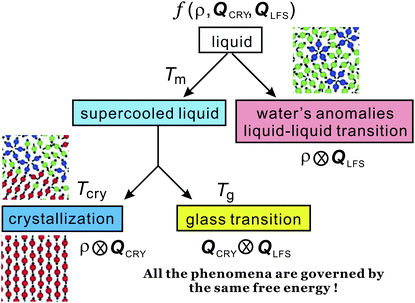 | ||
| Fig. 7 Schematic figure explaining the relationship between the behaviour of liquid upon cooling and the free energy. A liquid may exhibit water-like anomalies or LLT upon cooling. A liquid also becomes a metastable supercooled state below the melting point Tm and further cooling leads either to crystallization or to glass transition. The former takes place at the crystallization temperature Tcry, whereas the latter at the glass transition temperature Tg. The former is a thermodynamic phase transition, but the latter is a kinetic transition. The key fundamental question here is whether the glass transition behaviour is controlled by the same free energy as that for crystallization or a special free energy? We argue that all the phenomena are governed by the same free energy. | ||
4 Water's anomalies
4.1 Thermodynamic and kinetic anomalies of water
Liquid water exhibits many anomalous behaviours upon cooling, which include volume expansion (below 4 °C), softening (below 46 °C), and heat capacity increase (below 35 °C).3,6,9,73–75 In addition to the thermodynamic anomaly, the viscosity η also shows anomalous non-Arrhenius behaviour. Furthermore, at low temperatures η decreases up to 2 kbar and then increases with an increase in pressure,76 which is markedly different from the behaviour of ordinary liquids, whose η monotonically increases with pressure. All these features are absent in other molecular liquids. It is these unique properties that make water very special and important in nature. The unusual features of liquid water are more enhanced at lower temperatures and lower pressures, reflecting enhanced tetrahedral structures stabilized by hydrogen bonding. There is a consensus that the unique properties of water come from local tetrahedral ordering due to hydrogen bonding. This is supported by the fact that atomic liquids having similar tetrahedral ordering due to covalent bonding also exhibit water-like anomalies and phase behaviours.24These anomalous thermodynamic and dynamic behaviours of water have intensively been studied both experimentally and theoretically for a long time. Nevertheless, the very origin of the water anomalies is still a matter of debate and far from complete understanding.6,9,35,75
Many models of water have been proposed to explain the water's anomalies, focusing on the unique features of hydrogen bonding. The models can be classified into three groups:3,6,9,73–75,77 (a) a stability-limit conjecture,78 (b) a second-critical-point scenario (see e.g., ref. 3, 79, 80), and (c) a singularity-free scenario.81,82 Scenario (a) assumes the existence of a retracting spinodal curve and attributes the thermodynamic anomaly to proximity to the spinodal curve. Scenario (b), on the other hand, assumes the existence of a line of first-order transitions between two types of liquid water (low-density and high-density water), terminating at a critical point existing in a metastable state, and attributing the thermodynamic anomaly to critical phenomena associated with the hidden critical point. It is expected that a second critical point exists at a high pressure in the so-called no-man's land.3 Finally, scenario (c) predicts that the thermodynamic quantities exhibit extrema but no divergence.
In scenario (a), investigation of the thermodynamic properties of water at negative pressure will provide crucial information on its relevance.77 Scenario (b) is based on (i) experimental evidence of the presence of two amorphous forms of ices and a speculation on their connections to two types of liquids3,83,84 as well as (ii) support for the presence of LLT in model waters from numerical simulations.85 However, the connection between two amorphous ices and two liquids is also a matter of debate.86,87 Whether the transition between the amorphous ices has an equilibrium counterpart, with a first-order phase transition line above the glass transition temperature (Tg) that terminates at a critical point (LLCP), has recently become a matter of much controversy.88–95 A major source of difficulty lies in the fact that most modern theories of water concentrate on the supercooled region of the phase diagram, which is difficult to access by experiments due to the rapid crystallization of water below its melting line.6,96 Similar difficulties emerge also in simulations, where the lack of crystallization is sometimes hindered by the limited system sizes and time scales accessible.95 This is one of the major topics of this Faraday Discussion. We discuss this problem from a different viewpoint in section 7.8, focusing on a fundamental difference in the nature of the relevant order parameter between LLT and crystallization.
Both scenario (a) and (b) predict the anomalies of the thermodynamic and kinetic quantities due to the thermodynamic singularity. In these scenarios, the anomalies of the thermodynamic and dynamic quantities have often been analysed with the form of the power-law divergence, ε−γ, where ε = (T − Ts)/Ts (Ts: mean-field spinodal temperature) and γ is a critical exponent, and found to be well described by such relations. However, it should be noted that the critical exponents are often treated as adjustable parameters and no hyperscaling relations between the exponents have been found so far, unlike the case of the typical critical phenomena. Furthermore, we cannot approach to the mean-field spinodal temperature Ts so closely because homogeneous nucleation of ice crystals takes place far above Ts. Thus, the experimentally accessible range of ε is limited to ε > 0.05 in most cases and accordingly there has been no convincing evidence of the divergence of the thermodynamic quantities at a critical temperature. Note that for ordinary critical phenomena, we may approach a critical point to the order of ε ∼ 10−6–10−5. Here it is worth mentioning that the thermodynamics of water has recently been studied in detail on the basis of critical phenomena.80
Finally, scenario (c) predicts no divergence of the physical quantities. Focusing on the temperature dependence of hydrogen bonding, many rather complicated functional forms have been proposed to describe the anomalous behaviour of the thermodynamic and kinetic quantities.
Despite these considerable efforts, there has so far been no consensus on which of these three types of scenario is primarily responsible for the above-described anomaly of water or whether we need a new scenario or not.6 For example, there is still an on-going debate on the presence or absence of enhancement of density fluctuations that is a finger print of the singularity, since the singularity should cause critical-like enhancement of large-scale density fluctuations.97–101
Below we consider how the thermodynamic and kinetic anomalies of water-type liquids can be explained in the framework of our two-order-parameter model.
4.2 Prediction of our two-order-parameter model
Here we explain our two-order-parameter model of liquid.21,22 We first estimate how the average fraction of locally favoured structures,![[S with combining macron]](https://www.rsc.org/images/entities/i_char_0053_0304.gif) , increases with a decrease in T. From the condition ∂f(S)/∂S = 0 (see eqn (5)),
, increases with a decrease in T. From the condition ∂f(S)/∂S = 0 (see eqn (5)), ![[S with combining macron]](https://www.rsc.org/images/entities/i_char_0053_0304.gif) can be obtained as
can be obtained as | (9) |
The rather unique configurations of locally favoured structures and the existence of many possible configurations for normal liquid structures lead to the relation gρ ≫ gS. Then, ![[S with combining macron]](https://www.rsc.org/images/entities/i_char_0053_0304.gif) can further be approximated as
can further be approximated as
 | (10) |
![[S with combining macron]](https://www.rsc.org/images/entities/i_char_0053_0304.gif) ≪ 1.21,22
≪ 1.21,22
Hereafter we consider thermodynamic anomalies for a case of ![[S with combining macron]](https://www.rsc.org/images/entities/i_char_0053_0304.gif) ≪ 1. According to the above picture, the unusual decrease in ρ upon cooling below 4 °C in water can simply be explained by an increase in the number density of locally favoured structures,
≪ 1. According to the above picture, the unusual decrease in ρ upon cooling below 4 °C in water can simply be explained by an increase in the number density of locally favoured structures, ![[S with combining macron]](https://www.rsc.org/images/entities/i_char_0053_0304.gif) , upon cooling. The specific volume vsp and the density ρ are, respectively, given by
, upon cooling. The specific volume vsp and the density ρ are, respectively, given by
vsp(T,P) = vBsp(T,P) + Δv![[S with combining macron]](https://www.rsc.org/images/entities/i_char_0053_0304.gif) , , | (11) |
 | (12) |
 can straightforwardly be calculated from eqn (11) as
 | (13) |
![[S with combining macron]](https://www.rsc.org/images/entities/i_char_0053_0304.gif) .
.
The anomalous increase in the heat capacity at constant pressure CP upon cooling can also be explained as follows. The locally favoured structures have rather unique configurations and the associated degrees of freedom are much smaller for them than for the normal liquid structures of water. Thus, the entropy σ decreases upon cooling, reflecting an increase in ![[S with combining macron]](https://www.rsc.org/images/entities/i_char_0053_0304.gif) , or short-range tetrahedral ordering:
, or short-range tetrahedral ordering:
σ = σB(T,P) − Δσ![[S with combining macron]](https://www.rsc.org/images/entities/i_char_0053_0304.gif) , , | (14) |
 | (15) |
In this manner, all the thermodynamic anomalies can be expressed simply by the common Boltzmann factor, ![[S with combining macron]](https://www.rsc.org/images/entities/i_char_0053_0304.gif) . We confirmed the relevance of these relations by fitting the above functional forms to experimentally measured ρ, KT, and CP.20–22 Here we show only the temperature dependence of the Boltzmann factor,
. We confirmed the relevance of these relations by fitting the above functional forms to experimentally measured ρ, KT, and CP.20–22 Here we show only the temperature dependence of the Boltzmann factor, ![[S with combining macron]](https://www.rsc.org/images/entities/i_char_0053_0304.gif) , determined by the fitting of our prediction to the experimental data of ρ, KT, and CP at various pressures (see Fig. 8).
, determined by the fitting of our prediction to the experimental data of ρ, KT, and CP at various pressures (see Fig. 8).
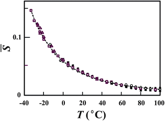 | ||
Fig. 8 Temperature dependence of ![[S with combining macron]](https://www.rsc.org/images/entities/i_char_0053_0304.gif) (see the text for its definition) determined by the fitting of our predictions to the experimental data of ρ, KT, and CP at various pressures. Open squares, triangles, and circles represent, respectively, data on ρ, KT, and CP at ambient pressure. All the other symbols are data at higher pressures. The dashed line is our theoretical prediction for (see the text for its definition) determined by the fitting of our predictions to the experimental data of ρ, KT, and CP at various pressures. Open squares, triangles, and circles represent, respectively, data on ρ, KT, and CP at ambient pressure. All the other symbols are data at higher pressures. The dashed line is our theoretical prediction for ![[S with combining macron]](https://www.rsc.org/images/entities/i_char_0053_0304.gif) . The values of . The values of ![[S with combining macron]](https://www.rsc.org/images/entities/i_char_0053_0304.gif) determined from the 23 sets of data of “bulk” liquid water are all collapsed on the master curve, which is described by the single Boltzmann factor. The figure is reproduced from Fig. 1(b) of ref. 21. determined from the 23 sets of data of “bulk” liquid water are all collapsed on the master curve, which is described by the single Boltzmann factor. The figure is reproduced from Fig. 1(b) of ref. 21. | ||
We also found that the kinetic anomalies of water such as viscosity anomalies can also be described by the same Boltzmann factor ![[S with combining macron]](https://www.rsc.org/images/entities/i_char_0053_0304.gif) (T,P).22,23 For example, the viscosity is known to exhibit a minimum as a function of pressure at a low temperature. This is a quite unusual phenomenon, but it can be naturally explained by the competition between the increase of the viscosity of normal liquid structures and the decrease of the fraction of locally favoured structures with an increase in P. We note that the presence of locally favoured structures leads to an extra activation energy for flow to take place and thus the decrease of S with an increase in P lowers this part of the viscosity associated with locally favoured structures.
(T,P).22,23 For example, the viscosity is known to exhibit a minimum as a function of pressure at a low temperature. This is a quite unusual phenomenon, but it can be naturally explained by the competition between the increase of the viscosity of normal liquid structures and the decrease of the fraction of locally favoured structures with an increase in P. We note that the presence of locally favoured structures leads to an extra activation energy for flow to take place and thus the decrease of S with an increase in P lowers this part of the viscosity associated with locally favoured structures.
It is known that the T-dependence of viscosity is well fitted by a power law, which is a prediction of mode-coupling theory (MCT).102–104 However, we showed that it can be equally well described by the modified Arrhenius law. Furthermore, the pressure dependence can be explained more naturally by our model.22,23
4.3 Comparison of our two-state model with previous mixture models
A mixture model of water was first proposed by Röntgen105 to explain water properties many years ago and then developed by many others (e.g., ref. 73, 106–110). It was recently applied to a water problem by Ponyatovsky et al.79 Their model regards water as a mixture of low-density (LDA) and high-density amorphous ice (HDA) (see also ref. 111). So it may be more appropriate to call this type of model a mixture model rather than a two-state model.Here we compare our model with such mixture models to clarify what physical factors are key to the description of water's anomalies. The most crucial difference between our model and the mixture models is the value of Δσ. We assume that the difference in entropy, or the degeneracy of states, between the two states is very large, which is a consequence of the disordered nature of normal liquid structures and the more unique nature of locally favoured structures. We note that normal liquid structures are also made of water molecules temporally hydrogen bonded with neighbouring molecules. The important point is that their structural order is still considerably lower than that of locally favoured structures (gρ ≫ gS). On the other hand, it is assumed (see, e.g., ref. 79) that the difference in the entropy between the two components is small since it is evaluated from the data of solid-state amorphous–amorphous (LDA–HDA) transition. In other words, it is implicitly assumed that both components have unique structures. Considering that a liquid is in a high entropy state and under significant thermal fluctuation effects, our two-state model approach seems to be more reasonable than such mixture model approaches. This subtle, yet crucial difference leads to a drastic difference in the physical picture. In our model, S is very small (S ≪ 1) at ambient temperature and pressure (see Fig. 8), but in most other models79,109,110S (in our terminology) is almost 1/2 or even higher there and in some cases the anomaly was ascribed to critical anomaly associated with the second critical point of LLT (see, e.g., ref. 79). In our case, water's anomalies are explained by a non-critical increase in S with decreasing T: the anomalous parts of physical quantities such as density are proportional to S and can be described by the Boltzmann factor at least in the experimentally accessible region (see eqn (10)).21,22
It is worth mentioning another reason why we prefer to use the term “two-state” rather than “mixture”. This is because a mixture model gives us an impression that a system is composed of A and B components and thus the order parameter (the fraction of A) is conserved. In reality, however, the order parameter should not be conserved: locally favoured structures are created and annihilated without the constraint from its conservation. This point is crucial when we consider the nature and the dynamics of water-like anomalies and liquid–liquid transition18,25 (see below).
Finally, we note a possible historical reason why S is estimated to be rather high. It may be related to the fact that the fraction of ice-like structures estimated from spectroscopic measurements such as Raman and infrared spectroscopy is usually rather high (see, e.g., ref. 73, 112, 113). So if we identify this fraction as the fraction of locally favoured structures, S is estimated to be large. However, our study indicates that there may be no direct connection between them and we need to pick up special modes linked to the translational order of the second shell,114 as will be described below.
4.4 Microscopic support for our two-order-parameter description from numerical simulations
In general, it is difficult to obtain detailed microscopic information on hydrogen bonding in water, and thus we cannot determine the difference in entropy between the two states in a convincing matter. We emphasize that the difference in Δσ leads to the entirely different scenarios for water's anomalies, as described above. This problem, which is directly related to the microscopic structural identification of normal liquid and locally favoured structures, is the key to our understanding of the physical origin of water's anomalies.Numerical simulations are obviously very powerful in identifying locally favoured structures. Recent simulation results115,116 seem to be consistent with our scenario, which predicts that S is rather small in the experimentally accessible region. Anisimov and his coworkers also showed that a two state model with cooperativity of entropic origin describes well the thermodynamic anomalies of mW water.117 Their results are also basically consistent with ours. However, we should also note that the estimate of the fraction of the LDL-like component by Cuthbertson and Poole is higher.118 Furthermore, Matsumoto showed that expansion of water upon cooling can be explained without invoking any heterogeneity.119 Thus, the situation has been quite controversial. The origin of the controversy is due to the lack of a proper structural order parameter for locally favoured structures of water.
Recently we successfully identified a structural order parameter for locally favoured structures of model water (TIP4P/2005) at a microscopic level. It is the degree of translational order in the second shell.114 The importance of the structure of the second shell was first shown by Soper and Ricci.120 This new structural order parameter allows us to estimate the T–P dependence of S directly from simulated water structures. We confirmed that the two-state model with the order parameter S that is independently determined in this way can well describe the thermodynamic anomalies. This provides the microscopic basis for our two-order-parameter model. The value of S was found to be low in the experimentally accessible region, consistent with the prediction of our two-order-parameter model (see above). We also showed that we can directly estimate S from the O–O radial distribution function, which provides a method to estimate S experimentally.
4.5 Do anomalies obey the Boltzmann factor or power law?
On the basis of these results, we argue that water's anomalies can basically be explained by our two-order-parameter model, or the Boltzmann factor, and not by power laws. This is supported by the fact that in model waters (TIP4P/2005114 and mW water117), which exhibits all the anomalies characteristic of water, quantities such as isothermal compressibility do not show any divergence at a finite temperature. Furthermore, the effects of cooperativity is very minor in the experimentally accessible region, even if there exists a second critical point. So we conclude that water's anomalies are primarily the consequences of Schottky-type anomaly characteristic to a two-state model, although further studies are necessary to confirm it in an unambiguous manner.4.6 Water-like anomalies in water-type atomic liquids
Here we briefly consider what makes water so special among ‘molecular’ liquids. We pointed out21,22,24 that water is the only molecular liquid for which local bond orientational ordering is basically compatible with a global crystallographic symmetry: the locally favoured tetrahedral structure of water stabilized by hydrogen bonding is basically consistent with the crystallographic symmetry of hexagonal ice Ih and cubic ice Ic, although there is some inconsistency in the symmetry.114 It is important to recognize that formation of a tetrahedral structure stabilizes hydrogen bonding with a help of local symmetry in a “cooperative” manner.We argue that all the thermodynamic anomalies of water originate from (i) this dominance of bond orientational ordering below a crossover pressure Px (∼2 kbar), where the melting point of ice crystals has a minimum, and (ii) an unusually large positive value of Δv. Below Px, the crystallization is due to bond ordering, while above Px it is due to density ordering as in ordinary liquids (see Fig. 9). This gives a natural explanation for the unusual pressure dependence of the melting point of ice crystals, including its minimum around 2 kbar. We propose that ice Ih is S-crystal, long-range ordering of S, while high-pressure ices are ρ-crystals.21,22,24 The V-shaped T–P phase diagram of water-type liquids is just a manifestation of the Clausius–Clapeyron relation.
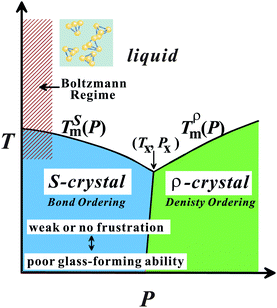 | ||
| Fig. 9 T–P phase diagram of water-type liquids including water itself and water-type atomic liquids (Si, Ge, Bi, Sb, and Ga). | ||
The above conditions (i) and (ii), which are necessary for having water-like anomalies, should be satisfied for tetrahedral liquids having V-shaped phase diagram. By using this specific shape of the phase diagram as a fingerprint,24 we classified five elements Si, Ge, Sb, Bi, and Ga into water-type atomic liquids. We showed that our two-order-parameter model of water indeed also explains the thermodynamic and dynamic anomalies of these water-type atomic liquids in a satisfactory manner.24
We discuss unique features of these liquids again in relation to the glass transition problem in section 6.13.
5 Liquid–liquid transition
Usually it is considered that atoms or molecules have random disordered structures in the gas and liquid states. This leads to a common sense view that any single-component substance has only one gas and one liquid state. On the other hand, it is widely known that even a single-component liquid can have more than two crystal forms, which is known as “polymorphism”. The uniqueness of the state is very natural and correct for gas, where the kinetic energy dominates. However, it is not so obvious for liquid since many-body interactions come into play, reflecting its high density, as we described above.Recently there has been growing experimental evidence that even a single-component liquid can have more than two liquid states.3,6,9,74,121–129 The transition between these liquid states is called “liquid–liquid transition” (LLT). There are also experimental indications for the presence of LLT in binary-component liquids such as AsS.130,131 The existence of liquid–liquid transitions has also been supported by a number of numerical simulations for atomic liquids such as Si132–135 and molecular liquids such as water.6,85,136,137 This phenomenon has attracted considerable attention not only because of its counter-intuitive nature but also from the fundamental importance for our understanding of the liquid state of matter. The connection between liquid–liquid transition and polyamorphism is also an interesting issue.
First we describe a simple phenomenological theory, which explains LLT as a transition between a gas state and a liquid state of locally favoured structures. Then we show some experimental pieces of evidence supporting the presence of LLT. However, most of such examples suffer from serious criticisms and thus the situation is quite controversial. Below we also discuss the source of controversies focusing on LLT in molecular liquids.
5.1 Phenomenological two-order-parameter model of liquid–liquid transition
In our model, LLT is described by the free energy f(S) given by eqn (5).25 The key term there is the coupling term JS(1 − S), which represents the cooperativity of formation of locally favoured structures. Thus, we first discuss possible origins of the cooperativity.One is the microscopic cooperativity of directional bonding, which is related to the change in the electronic state by the formation of locally favoured structures. This effect may be important in liquids have directional bondings such as hydrogen and covalent bonding. Its importance is particularly clear for liquids such as Si and Ge, for which transitions accompany a drastic change in the electronic properties and induce metal–semiconductor transitions. How to incorporate the electronic degrees of freedom into our phenomenological model is an interesting but challenging problem. The second is the modification of the degrees of freedom around locally favoured structures due to the local reduction of configurational and vibrational entropy. The third is a possible role of long range van der Waals forces, which are due to the difference in density between locally favoured structures and normal-liquid structures, δρ. The interaction strength may be estimated as
| U ∼ U11(δρ/ρ)2(b/a), | (16) |
The equilibrium value of S is determined by the condition ∂f(S)/∂S = 0, or
 | (17) |
| Sc = 1/2, | (18) |
| Tc = J/(2kB), | (19) |
| Pc = [ΔE − TcΔσ]/Δv. | (20) |
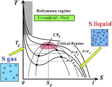 | ||
| Fig. 10 Schematic phase diagram of liquid–liquid transition in T–S plane.25 Liquid–liquid transition can be understood as a transition between a S-gas state and S-liquid state. | ||
A first-order phase-transition temperature Tt is obtained as
| Tt = (ΔE − PΔv)/Δσ. | (21) |
Note that a first-order transition occurs only if Tt < Tc. For Tt > Tc, this Tt is a temperature where ΔG = 0 and thus ![[S with combining macron]](https://www.rsc.org/images/entities/i_char_0053_0304.gif) = 1/2. The maximum of KT is also located near Tt. Δv may be positive for liquids such as water and Si, but it can also be negative for liquids such as triphenyl phosphite (see below and ref. 138, 139). The sign of Δv determines the slope of Tt(P). Liquid I and liquid II are defined as the two possible minima of the liquid-state free energy on the ρ–S plane.
= 1/2. The maximum of KT is also located near Tt. Δv may be positive for liquids such as water and Si, but it can also be negative for liquids such as triphenyl phosphite (see below and ref. 138, 139). The sign of Δv determines the slope of Tt(P). Liquid I and liquid II are defined as the two possible minima of the liquid-state free energy on the ρ–S plane.
Now we consider the kinetics of LLT. In LLT, the bond order parameter S plays essential roles, and the density order parameter ρ is slaved by S. Using δS = S − ![[S with combining macron]](https://www.rsc.org/images/entities/i_char_0053_0304.gif) , we introduce the following minimal Landau-type free energy density by expanding f(S) in terms of δS, which governs S fluctuations near a gas–liquid-like critical point or mean-field spinodal lines of bond ordering, where S = SSD:
, we introduce the following minimal Landau-type free energy density by expanding f(S) in terms of δS, which governs S fluctuations near a gas–liquid-like critical point or mean-field spinodal lines of bond ordering, where S = SSD:
 | (22) |
 ,
,  ,
,  , and
, and  . In the last relationship, we use ∂f/∂S = ∂2f/∂S2 = 0 at T = T*SD. In the above, Θ is the scaled temperature: Θ = (T − T*SD)/T, where T*SD is a critical or spinodal temperature of bond ordering without the coupling to ρ, and b2 and b4 are positive constants. By further including the gradient term, we obtain the following Hamiltonian that we believe is relevant to the physical description of a gas–liquid-like transition of locally favoured structures (see Fig. 10):25
 | (23) |
For simplicity, we assume the density ρ is given as a function of S as follows: ρ(![[r with combining right harpoon above (vector)]](https://www.rsc.org/images/entities/i_char_0072_20d1.gif) ) = ρN(1 − S(
) = ρN(1 − S(![[r with combining right harpoon above (vector)]](https://www.rsc.org/images/entities/i_char_0072_20d1.gif) )) + ρSS(
)) + ρSS(![[r with combining right harpoon above (vector)]](https://www.rsc.org/images/entities/i_char_0072_20d1.gif) ), where ρN is the density of the normal-liquid structures and ρS is the density of the locally favoured structures. For Δv < 0, which is a case of TPP, an increase in S leads to an increase in ρ.
), where ρN is the density of the normal-liquid structures and ρS is the density of the locally favoured structures. For Δv < 0, which is a case of TPP, an increase in S leads to an increase in ρ.
In our previous papers,18,25,140 we employed a more complex coupling between ρ and S, which leads to the constraint for the global density. However, experiments are usually performed at constant pressure and there is no constraint for the total density. Indeed, our light scattering experiments on LLT in triphenyl phosphite show that the scattering intensity at the wavenumber q → 0 grows upon LLT, which is characteristic of the correlation function of a non-conserved order parameter. Although we need a more complete description, which takes into account the couplings to the density (mass conservation), velocity fields (momentum conservation), and temperature fields (energy conservation), we here stick to the simplest version of the kinetic theory. Here we note that Takae and Onuki recently investigated the roles of latent heat on LLT. This might also play an important role141 when local heating induced by LLT takes place due to a weak thermal contact between the sample and the temperature bath.
Since locally favoured structures can be created and annihilated without the constraint of its conservation, the order parameter S should obey the kinetic equation describing the time evolution of the non-conserved scalar order parameter S:25
 | (24) |
The type of pattern evolution is grouped into nucleation–growth (NG)-type in a metastable state (above TSD) and spinodal-decomposition (SD)-type in an unstable state (below TSD). Here TSD is the spinodal temperature. NG-type LLT is characterized by nucleation of droplets overcoming the activation barrier by thermal noises and its growth with a constant velocity. SD-type LLT is characterized by spontaneous growth of order parameter fluctuations, whose amplitude grows exponentially in the early stage. In both cases, the final state becomes homogeneous again at a constant pressure condition, which is a consequence of the non-conserved nature of the order parameter S.
However, this mean-field picture suggesting a sharp transition between NG- and SD-type dynamics breaks down under thermal fluctuation effects and the transition becomes broader142,143 except for systems of long-range interactions.25
5.2 Current situations and controversies
Once we accept the formation of locally favoured structures in liquids and its cooperativity, it is natural to assume the presence of LLT. Since it is rather hard to imagine that locally favoured structures are formed completely independently without any cooperativity, we expect that liquid–liquid transitions can exist in many liquids.25 However, the energy scale of the coupling parameter J is often comparable to the energy scale controlling other cooperative ordering such as crystallization, since both are determined by the common interaction potential. Thus, liquid–liquid transition may often be hidden by crystallization, particularly if the symmetry of locally favoured structures is similar to that of the equilibrium crystal. This may be the source of controversy concerning whether or not liquid–liquid transition exists in many systems including the case of water (see also section 7.8). From a theoretical viewpoint, thus, it is crucial for deeper understanding of LLT to elucidate the microscopic mechanism of formation of locally favoured structures and its cooperativity.Here we note that mixing a target liquid with another liquid that can prevent crystallization may be a good strategy to reveal such a hidden LLT, since LLT may take place even after mixing with other fluids.144 We actually employed this method in our study of LLTs of aqueous organic solutions145,146 (see below).
In some model liquids such as the Jagla model,147,148 a liquid–liquid transition is clearly seen. So the presence of LLT in liquids itself has been accepted at least theoretically. For realistic models, however, the situation is controversial even in numerical simulations, as mentioned above. For example, as we see in this Faraday Discussion, whether LLT exists in model waters or not has recently become a matter of much controversy. Some simulations support the presence,88–92 whereas the others do not.93–95,149 This is the case even for the same ST2 water model. A major source of difficulty lies in the fact that LLT exists in a state thermodynamically metastable or unstable against crystallization. Thus the lack of crystallization may be hindered by the limited system sizes and time scales accessible.95 During the meeting we do not see any consensus on this problem. We discuss this issue from a different viewpoint in section 7.8.
Experimentally, there are also few cases for which there is a consensus on the existence of LLT. This is mainly due to the fact that LLT exists in a region which is difficult to access experimentally: for atomic liquids LLT exists at very high temperature and pressure, whereas for molecular liquids it exists only in a metastable state, where crystallization can take place. Because of such difficulties, the situation still remains very controversial.
First we review the case of atomic liquids. For example, Katayama et al. discovered the first order LLT in phosphorus at high pressure and high temperature with synchrotron X-ray scattering.125,126 They revealed the structure factors for both liquid I and II and confirmed the coexistence of liquid I and II during the transition, which clearly suggests the first-order nature of the transition. The distinct change in the structure factor suggests that LLT in phosphorus is the transformation from tetrahedral to polymeric liquid. This is one of the clearest examples of a transition between two isotropic fluids. Such a structural transition was also observed by the first principle simulation performed by Morishita.150 However, Monaco et al.127 concluded that the first-order transition in P is between a high-density molecular fluid (not a liquid in the exact sense) and a low-density polymeric liquid. Thus, the transition is now regarded as a ‘supercritical fluid’–liquid transition rather than a liquid–liquid transition. This explains an unusually large difference in the density between the two states. The existence of LLT in liquid Si was also suggested by high-pressure experiments122,151,152 and numerical simulations,132–134 but the presence of LLT still needs to be checked carefully. LLT was also reported in yttria–alumina.121,122,153–155 However, there are also still on-going debates on the composition range over which this phenomenon occurs and the experimental conditions required to observe it156 and even on its existence itself.157
For molecular liquids, Mishima et al. found an amorphous–amorphous transition in water.158 The transition has recently been studied in detail.6 From the presence of the two forms of amorphous states, the presence of LLT has been inferred. Computer simulations also suggested the existence of LLT(s) in water.3,6,123,136,137,159 On the basis of these findings, the connection of amorphous–amorphous transition and LLT in water was suggested and actively studied.3,6 Some simulations support this connection,86 others not.87 In real water, the LLT is hidden by crystallization, even if it exists. This makes an experimental study on the LLT extremely difficult especially for bulk water. It was also pointed out that the mechanical nature of amorphous–amorphous transition makes its connection to thermodynamic LLT indirect, even if it exists.21 As mentioned above, even for numerical simulations, difficulties associated with the distinction between LLT and crystallization in a deeply supercooled liquid make the situation very controversial.
This situation has been improved by recent direct observation of LLT at ambient pressure in molecular liquids, triphenyl phosphite (TPP)160,161 and n-butanol.162 We observed both NG-type and SD-type LLT, which is well explained by our scenario that liquid–liquid transition is a consequence of the cooperative ordering of a non-conserved scalar order parameter, which is the fraction of locally favoured structures, S(![[r with combining right harpoon above (vector)]](https://www.rsc.org/images/entities/i_char_0072_20d1.gif) ). However, this phenomenon was also claimed by Hédoux et al.163–169 to be induced by the formation of micro-crystallites rather than LLT. Recently, a similar claim was also made for n-butanol.170–172 In this scenario, what we call liquid II is merely a mixture of liquid I and micro-crystallites.
). However, this phenomenon was also claimed by Hédoux et al.163–169 to be induced by the formation of micro-crystallites rather than LLT. Recently, a similar claim was also made for n-butanol.170–172 In this scenario, what we call liquid II is merely a mixture of liquid I and micro-crystallites.
So strictly speaking, there has been no firm consensus on the existence of LLT for any substance from the experimental side, and it remains a matter of serious debate whether the above-mentioned phenomena are the true evidence of LLT or not. Theoretically, on the other hand, the generality of LLT, or possible existence of LLT in various types of liquids, was recently discussed on the basis of phenomenological18,25 and analytical models.173–176
Below we review our study on LLTs in molecular liquids and then discuss the controversies on the nature of the transition for these examples.
5.3 LLT observed in single-component molecular liquids
Some time ago Kivelson and coworkers reported the following unusual phenomena observed in a supercooled state of TPP.138,177,178 When TPP is cooled rapidly and deeply enough, it first enters into a supercooled liquid state below the melting point Tm as usual liquids, and then frozen into a glassy state, which we call glass I. This supercooled liquid (liquid I) behaves as a typical fragile glass former. On the other hand, when TPP is quenched to a certain temperature between 213 K and 223 K and then annealed at that temperature, a new apparently amorphous phase (the so-called glacial phase) is formed in a supercooled liquid and thus the system becomes inhomogeneous and optically turbid. Eventually, however, the system completes the transformation into the glacial phase. Surprisingly, the glacial phase is apparently an optically transparent homogeneous amorphous phase, but it is obviously different from ordinary liquid (liquid I) and glass (glass I).This finding stimulated intensive experimental research on this unusual phenomenon. However, the nature and origin of the glacial phase has been a matter of debate and many different, even controversial, explanations have been proposed for it. The glacial phase was thought to be a new amorphous phase178–181 or a highly correlated liquid.182 However, most researchers, including us, have shown that the glacial phase has some crystallinity or anisotropy. Hence the newly formed glacial phase appears to be neither a standard glass nor a liquid. It is this that has led some researchers to conclude that the glacial phase is actually some type of defect-ordered crystals (orientationally disordered or modulated crystal),138,178,183 liquid crystal,184 plastic crystal,181,184 aborted crystallization,163–169 or nano-clustering.185
To access the nature of the transition, we directly observed the process of liquid–liquid transition with optical microscopy for two pure organic liquids, triphenyl phosphite (TPP)160,161 and n-butanol.162 When we quench and anneal TPP in the metastable region with respect to LLT, droplets of liquid II are randomly nucleated in both space and time in liquid I and the domain size R grows with a constant interface velocity as R ∝ t (see Fig. 11(a)).160–162 In the late stage, droplets of liquid II collide, coalesce, and further grow. This behaviour is characteristic of the NG behaviour. Then, the new phase covers the entire region and eventually the boundary between droplets tends to disappear; and, thus, liquid I almost transforms to homogeneous liquid II (see Fig. 11(a)). This is a consequence of the non-conserved nature of S and the off-symmetric quench. If the LLT were governed by a conserved order parameter, the diameter would grow in proportion to t1/3 and the system would never become homogeneous again,186 as long as we do not cross the binodal lines twice.187 We also observed SD-type LLT, which occurs when a liquid is quenched into an unstable region below TSD160,161 (see Fig. 11(b)). The initial stage is reminiscent of the Cahn's linear regime.186 In the beginning, the amplitude of fluctuations exponentially grows with time and thus the contrast increases. Then, the domain size and the contrast both increase. Later the liquid becomes more homogeneous, which leads to the decrease in the contrast. Finally, the liquid becomes almost homogeneous liquid II. These observations are basically consistent with the prediction of our model. The heat evolution was also measured during LLT. This is also consistent with our model, which assumes that LLT is a consequence of the cooperative formation of locally favoured structures with a lower local free energy. According to our model, provided that the amount of nano-crystallites formed during LLT is negligible, which is the case for LLT at a low temperature below TSD, the heat evolution is proportional to the development of the bond order parameter S, since the heat is released in the process of the formation of locally favoured structures. This was supported by the structural study of the process of LLT by X-ray scattering.188 However, the interpretation is complicated by the presence of micro- or nano-crystallites, which are formed during the transformation. We confirmed that LLT accompanies the formation of micro- or nano-crystallites at rather high temperatures (above 214 K), but at low temperatures (e.g., at 212 K) the amount of crystals becomes very small. On the basis of these experimental results, we concluded that this transformation is actually a transition from a supercooled state of liquid I to a glassy state of liquid II.
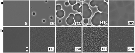 | ||
| Fig. 11 Pattern evolution observed with phase-contrast microscopy during the annealing of a supercooled liquid at Ta. (a) Experimental results for TPP at Ta = 219 K. The intensity is proportional to the refractive index. The size of each image is 120 μm × 120 μm. The contrast between droplets (liquid II) and the matrix (liquid I) decreases with an increase in the distance from the interface (decay length: a few microns). This is due to non-ideality of phase contrast microscopy, and does not mean the change in the refractive-index difference. (b) Experimental results for TPP at Ta = 214 K, observed with phase-contrast microscopy. The size of each image is 150 μm × 150 μm. The number in each image indicates the elapsed time in minutes for both (a) and (b). | ||
We also find that liquid II is stronger than liquid I and the fragility monotonically decreases in the transformation process from liquid I to II. Fig. 12 shows how the upper and lower edge of the glass transition (THg andTLg, respectively) and the ideal glass transition temperature T0 are dependent on the normalized order parameter ![[S with combining tilde]](https://www.rsc.org/images/entities/i_char_0053_0303.gif) , which monotonically increases with time during the transformation from 0 to 1. This suggests189 that the fragility is not a material specific property, but rather controlled by the strength of frustration against crystallization (see section 6). This conclusion was supported by the recent experimental study on the pressure effect on the fragility of liquid II.139
, which monotonically increases with time during the transformation from 0 to 1. This suggests189 that the fragility is not a material specific property, but rather controlled by the strength of frustration against crystallization (see section 6). This conclusion was supported by the recent experimental study on the pressure effect on the fragility of liquid II.139
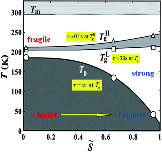 | ||
Fig. 12 The dependence of the upper and lower edge of the glass transition (THg andTLg, respectively) and the ideal glass transition temperature on the normalized order parameter ![[S with combining tilde]](https://www.rsc.org/images/entities/i_char_0053_0303.gif) for TPP. for TPP. | ||
Here we also mention the difference in the physical and chemical properties of liquid I and II of TPP. First of all, liquid II has a higher density and a higher refractive index than liquid I. The glass transition point of liquid II is much higher than liquid I, which means the difference in the fluidity between them. As described above, liquid II is less fragile than liquid I. We also found144 that liquid I is miscible with diethyl ether, but liquid II is not when TPP is mixed with a sufficiently high concentration of diethyl ether. As shown in Fig. 13, whether diethyl ether can mix with TPP depends not only on the concentration of diethyl either Φ, but also the order parameter S. This clearly shows that liquid I and liquid II may have a different miscibility with other liquids. We note that both liquid I and II of TPP are miscible with toluene.144 We also revealed that liquid I and liquid II have different wettability to a solid substrate.190 Thus, liquid I and liquid II have differences in density, refractive index, dielectric constant, glass transition point, fragility, fluidity, miscibility, and wettability.
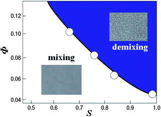 | ||
| Fig. 13 The phase diagram showing the miscibility of TPP with diethyl ether on the two-order-parameter plane of the concentration of diethyl either Φ, and the order parameter S at T = 209 K. | ||
In the case of n-butanol, we observed the pattern evolution behaviour almost identical to that in TPP.162 However, crystallization always occurs even at a low temperature below TSD, the crystallinity is higher than in the case of TPP, and thus the situation is a bit more complicated. For example, Ramos and his coworkers recently claimed that the phenomena observed in n-butanol is aborted crystallization and not LLT,170,171 but we still argue that it is LLT on the basis of the kinetic features of the transformation process (see below).
5.4 LLT in a mixture of water and glycerol
Next we describe our efforts to access a possibly hidden LLT in water experimentally. Unlike the cases of TPP and n-butanol, experimental verification of LLT in water is quite difficult due to the interference by instantaneous crystallization. There may still be a few routes to access a hidden LLT in water, if it exists. One strategy is to use water confined in nm-size pores191,192 or to use protein-hydration water.193 These works show evidence suggestive of a fragile-to-strong liquid transition and LLT. However, these experiments inevitably suffer from criticisms that water confined into a nm-scale space surrounded by a wall is intrinsically different from bulk water because of the presence of water–wall interactions and the reduced dimensionality.194–196 It was shown,194 for example, that (i) without a special care we cannot conclude even whether water inside a nm-size pore is liquid or solid or amorphous or crystalline and (ii) the interaction with the wall makes the confined state inhomogeneous. We also refer the paper presented by Torre in this Faraday Discussion,197 which indicates significant structuring of water near the hydrophilic surface. Since the presence of the amorphous–amorphous transition in bulk does not prove the presence of LLT either (see above), it may be fair to say that we do not have any firm experimental evidence for LLT in water yet, although there are many implications (see, e.g., ref. 83).Recently we took a different strategy: mixing water with glycerol to avoid crystallization of water. Note that glycerol is a well-known cryoprotectant non-crystallizable liquid and can cause strong frustration against water crystallization (see, e.g., ref. 199, presented at this Faraday Discussion). In an aqueous glycerol solution we found the direct experimental evidence for genuine (isocompositional) LLT without accompanying demixing.145 We confirmed that liquid I transforms via the two types of kinetics characteristic of the first-order transition of a non-conserved order parameter, NG and SD, towards homogeneous liquid II (see Fig. 14). The processes of pattern evolution are strikingly similar to those observed in TPP, strongly indicating that the nature of the transition should be the same between TPP and water–glycerol mixtures. The state diagram of water–glycerol mixtures is shown in Fig. 15. The liquid–solid phase diagram of water–glycerol mixtures is very similar to the T–P phase diagram of pure water, which also has a V-shape. We found that liquid I and II differ in the density, the refractive index, the structure, the hydrogen bonding state, the glass transition temperature, and the fragility. We revealed that this transition is mainly driven by local structuring of water rather than glycerol, suggesting a possible link to LLT in pure water.
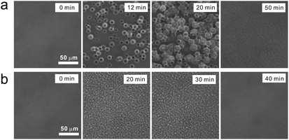 | ||
| Fig. 14 (a) NG-type pattern evolution during LLT at T = 180 K for c = 0.165. (b) SD-type pattern evolution at T = 173 K for c = 0.165. In both cases, the initial state is liquid I and the final state is liquid II. The patterns were observed with phase contrast microscopy. White bars correspond to 50 μm. | ||
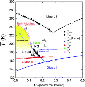 | ||
Fig. 15 Glycerol concentration vs. temperature (c–T) state diagram of water–glycerol mixtures. TSD: LLT spinodal temperature (black filled circles); TgI: the glass transition temperature of liquid I (blue filled triangles). For pure water (c = 0), we use the widely accepted value of 136 K![[thin space (1/6-em)]](https://www.rsc.org/images/entities/char_2009.gif) 6 for TgI; TgII: the glass transition temperature of liquid II (red filled triangles). Dot-dashed line indicates TgII of pure liquid II without ice Ic, provided that liquid II contains ϕc = 17% of ice Ic, which should result in the increase in the glycerol mole fraction of liquid II by 6.4%; TH: the homogeneous nucleation temperature (violet open circles) measured for the cooling rate of 100 K min−1; Tx: the transition temperature from ice Ic to Ih, which was determined by microscopy observation (green filled diamonds); Tm: the melting (liquidus) temperature (black filled squares: our data; open squares: the data of Lane198). We make a linear extrapolation of TSD to estimate the position of a hypothetical critical point (CP) (light blue open circle), since we cannot access TSD for c < 0.13 due to rapid nucleation of ice Ih before reaching the final target temperature in the quench process. For c > 0.19, on the other hand, the kinetics of LLT drastically slows down, which also prevents us from accessing LLT during the observation time. Finally we note that the TSD we measured is the stability limit of liquid I, and we could access neither the binodal line nor the stability limit of liquid II because of interference by ice crystallization. This figure is reproduced from Fig. 4 of ref. 145. 6 for TgI; TgII: the glass transition temperature of liquid II (red filled triangles). Dot-dashed line indicates TgII of pure liquid II without ice Ic, provided that liquid II contains ϕc = 17% of ice Ic, which should result in the increase in the glycerol mole fraction of liquid II by 6.4%; TH: the homogeneous nucleation temperature (violet open circles) measured for the cooling rate of 100 K min−1; Tx: the transition temperature from ice Ic to Ih, which was determined by microscopy observation (green filled diamonds); Tm: the melting (liquidus) temperature (black filled squares: our data; open squares: the data of Lane198). We make a linear extrapolation of TSD to estimate the position of a hypothetical critical point (CP) (light blue open circle), since we cannot access TSD for c < 0.13 due to rapid nucleation of ice Ih before reaching the final target temperature in the quench process. For c > 0.19, on the other hand, the kinetics of LLT drastically slows down, which also prevents us from accessing LLT during the observation time. Finally we note that the TSD we measured is the stability limit of liquid I, and we could access neither the binodal line nor the stability limit of liquid II because of interference by ice crystallization. This figure is reproduced from Fig. 4 of ref. 145. | ||
In relation to this, it was recently pointed out by Towey and Dougan200 that glycerol molecules act to “pressurize” water. This further suggests a link between a water–glycerol mixture and pure water. However, we note that there is also a change in the vibrational modes of glycerol molecules upon LLT145 and thus we cannot deny a possibility that LLT occurs only in solutions and not in pure water. Thus, further study is necessary to clarify whether water has LLT without glycerol or not.
5.5 Controversy on the nature of the transition: LLT or formation of nano-crystallites
First we consider the characteristics of pattern evolution observed by optical microscopy. We observed NG-type and SD-type pattern evolution, which can be naturally explained by our scenario, as already explained above. If we take the crystallization scenario, we may still regard droplets formed in the NG-type process as ordinary spherulites with low crystallinity and growth of fluctuations in the SD-process as homogeneous nucleation. However, it is difficult to explain by this scenario why a system becomes inhomogeneous in the beginning but later becomes homogeneous. We might explain this by replacing locally favoured structures by nano-crystallites in our two-order-parameter model of LLT, or assuming cooperative crystal nucleation. However, this model seems not to be so realistic and we need an intrinsic mechanism preventing the growth of nano-crystallites and stabilizing them at a nm-scale size. It is also not so easy to explain why a non-crystallized remaining liquid becomes a glass even far above the glass transition of the original liquid. One possible explanation is that the dynamics of a liquid confined by nano-crystallites slows down and becomes glassy. However, this interfacial liquid (or, confinement) scenario cannot explain why the glass transition temperature of the glacial phase is not so sensitive to the amount of nano-crystallites, which is largely changed by the annealing temperature. According to this scenario, with a decrease in the amount of nano-crystallites, the glass transition should be more similar to that of pure liquid I, but what is observed is the opposite. In relation to this, we should note that the glass transition of liquid II is very broad, which we interpreted as a signature of the strong nature of liquid II160,189 and a possible broad distribution of S due to vitrification in the course of LLT (see Fig. 16 and below). In the crystallization scenario, we might be able to explain this broadness by the spatial distribution of the relaxation time, which is controlled by the distance from the surfaces of nano-crystallites. The temporal change in the broadness of the transition during SD-type LLT189 may be explained by both scenarios at least qualitatively.
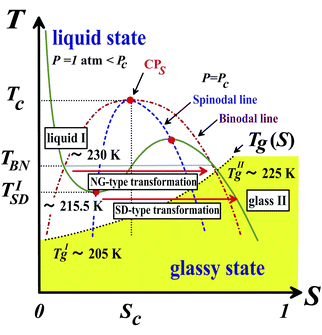 | ||
| Fig. 16 Schematic T–S phase diagram of TPP. The dashed and dot-dashed lines are spinodal and binodal lines, respectively. CPS is a gas–liquid-like critical point of the bond order parameter S, which might exist at a high pressure. The dotted curve is the glass transition line Tg(S) and the yellow region corresponds to a glassy state. TBN and TISD represent the binodal temperature and the lower spinodal temperature at atmospheric pressure, respectively. Note that the liquid I → liquid II (glass II) transition inevitably accompanies vitrification, which makes a glass II state non-equilibrium in the sense that both ρ and S cannot reach their equilibrium values. This figure is reproduced from Fig. 22 of ref. 35. | ||
In relation to this, it is worth mentioning a mysterious character of liquid II: liquid II is a strong liquid, but exhibits a very broad structural relaxation spectrum. Usually, a strong liquid has a narrow distribution of the relaxation time.9,201 We explain this as follows: a glassy state of liquid II is formed as a consequence of LLT (see Fig. 16) and the broad distribution of the order parameter S as a consequence of the SD-type ordering161 is frozen by vitrification before becoming narrow. Within the crystallization scenario, we may interpret this as a consequence of the spatial distribution of the relaxation time (see above).
Next we consider the heat production during LLT. The heat released during LLT is much larger than that expected for the amount of nano-crystallites. Even when we detect little indication of nano-crystallite formation by X-ray scattering (below 215 K), there is a significant release of heat during LLT (see, e.g.ref. 160, 202). These are also difficult to explain by the aborted crystallization scenario. We might still be able to argue that nano-crystallites are too small to detect by X-ray scattering, but then it becomes almost impossible to distinguish liquids and crystals any more.
Furthermore, we recently found an indication suggestive of the formation of locally favoured structures whose size is about 3 nm and the increase of the fraction with time during LLT by time-resolved small-angle X-ray scattering measurements.203 In the process, we observe little change in the wide-angle diffraction pattern. This suggests that this signal is from locally favoured structures, and not from nano-crystallites, which supports our scenario rather than the aborted crystallization scenario.
We also found that when we mix TPP with toluene, the final liquid II has a fluidity and has a glass transition temperature Tg different from the initial liquid I.144 In the NG-type LLT, we also observed droplet formation. On noting that liquid II has a fluidity in the mixture, it is difficult to explain by the crystallization scenario what maintains the interface between the two liquids, or the origin of the interfacial tension. It is not obvious whether the liquid and the same liquid containing nano-crystallites can form the sharp interface or not. We need an exotic mechanism to explain it. A scenario of a colloidal gas–liquid transition might explain the formation of a sharp interface itself, but it cannot explain the final homogeneization in a simple manner. To explain the phenomenon with this scenario, we have to assume that nano-crystallites of TPP, which do not grow in size, are kept formed in the mixture selectively at the interface. We also found that the Tg of liquid II is higher than that of liquid I.144 We note that toluene is not crystallized in the mixture and the Tg of toluene is lower than that of TPP. In the aborted crystallization scenario, toluene should be enriched in a non-crystallized liquid I region and thus we expect that the Tg of liquid II is lower than that of liquid I, provided that there is a significant amount of micro-crystallites that is large enough to account for the amount of the heat released during LLT. This is inconsistent with our observation: the Tg of liquid II is higher than that of liquid I for TPP–toluene mixtures. Furthermore, we also found that liquid I is miscible with diethyl ether, but liquid II is not.144 This result is also difficult to explain by the crystallization scenario.
We also observed significant surface wetting effects for liquid II.190 If this is induced by the ordinary dispersion force, we might be able to explain this by the crystallization scenario. But we found that the wetting effects are induced by specific interactions associated with hydrogen bonding and not by a dispersion force. This strongly indicates that the wetting phenomena are induced by the difference in the microscopic nature between the two liquids, and not by the difference in the macroscopic properties coming from the fraction of micro-crystallites. It also suggests the important role of hydrogen bonding in the transition, supporting our scenario.
Next, we consider why we observed a Maltese cross pattern for droplets of liquid II (see Fig. 17(a)). At first glance, droplets look like ordinary crystalline spherulites, but we note that the strength of birefringence is extremely weak, compared to crystal spherulites formed at a high temperature above the binodal line of LLT (see Fig. 17(b)). To explain the presence of a Maltese cross pattern, we need to explain why crystals have specific orientation along the growth direction in the framework of our scenario. Our explanation is as follows. First we mention that liquid II is completely wettable to crystals (see Fig. 17(b)),190 indicating the interfacial energy of crystals is significantly lower for liquid II than for liquid I. Another important fact is that liquid II is a glass and not a liquid. In particular, in the NG-type process droplets of high S is directly nucleated and thus it is likely that droplets are nucleated in a glassy state. These considerations lead to a conclusion that a region where crystal nucleation can take place may be exclusively the droplet interface region since only there the two important conditions for crystal nucleation, high mobility and low nucleation barrier, are met (see Fig. 17(c)). A low nucleation barrier is a consequence of a low interfacial tension between liquid II and crystals. So we expect crystal nucleation selectively occurs in the interfacial region and then crystals grow towards an outward direction perpendicular to the interface, which is selected by the mobility gradient ∇S. This provides a natural explanation on why nano-crystallites have special orientations in liquid II droplets along the radial direction.
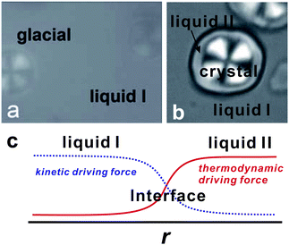 | ||
| Fig. 17 (a) Droplets of the glacial phase observed with polarizing microscopy under the crossed Nicols condition (60 min at Ta = 220 K). (b) Formation of liquid II in the presence of TPP crystal spherulites formed at 237 K, which was observed with polarizing microscopy under the crossed Nicols condition. The layer of liquid II, which has no birefringence, is formed on the surface of the TPP spherulite (60 min after quenching to 220 K). We can clearly see liquid II completely wets the pre-existing crystal spherulite. (c) Schematic figure showing the spatial change in the kinetic driving force for crystal nucleation (mobility) and the thermodynamic driving force determined by the crystal–liquid interfacial tension. The total driving force should be maximum at the interface. | ||
Finally we discuss the difference in the temperature dependence of the growth velocity V and the nucleation frequency Γ between spherulites of the crystal and droplets of the glacial phase (liquid II droplets in our scenario). We found that both V and Γ of the glacial phase obey curves different from those of the crystal (see Fig. 18), indicating that droplets of the glacial phase is distinct from spherulites of the crystal. This might be explained if we assume that the symmetry of the crystal formed in the glacial phase is different from that of the ordinary crystal. However, the X-ray and neutron diffraction peaks of micro-crystallites formed in the glacial phase is identical to that of the ordinary crystal formed at a high temperature.167,204 Thus, it is difficult to explain the above fact by the crystallization scenario.
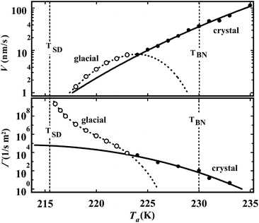 | ||
| Fig. 18 Dependence of the growth velocity V (a) and the nucleation frequency Γ (b) on the annealing temperature Ta for the crystal (filled circle) and the glacial phase (open circle). This figure is reproduced from Fig. 2 of ref. 160. | ||
On the basis of these considerations, we conclude that the transition observed in TPP is more naturally explained by LLT rather than the crystallization scenario, although further careful study is necessary to completely settle this problem.
The transition in a water–glycerol mixture, which we interpreted as LLT, was also interpreted in a different way. Feldman and his coworkers interpreted the final state as a mixture of the solute-rich liquid I phase, ices, and interfacial water around ices, on the basis of dielectric spectroscopy measurements.205,206 Recently Limmer and Chandler95 also suggested the possibility that the phenomena we interpret as LLT in a water–glycerol mixture may be a process of the liquid-to-crystal transition coupled with solute concentration fluctuations. This scenario can also explain the fact that the time over which this coarsening occurs is much longer than the relaxation time of the liquid. It also predicts that for NG-type evolution droplets are rich in ices and interfacial water, whereas the matrix is rich in glycerol. This is because ices are more friendly to interfacial water than glycerol, which causes attraction between ice crystals. Since LLTs in the systems we investigated always accompany the formation of cubic ices, these scenarios should be carefully examined. These proposals have similarity to the aborted crystallization scenario proposed for TPP.
We first examine the above-mentioned prediction suggesting possible enrichment of glycerol in the matrix phase. Contrary to it, we recently confirmed by micro-Raman spectroscopy that the glycerol concentration is the same between droplets and the matrix. This means that the glycerol concentration is spatially almost homogeneous in liquid II. This situation is similar to that in a mixture of TPP and toluene.144 Next we consider the glass transition of the state we call liquid II. For this state we found a single glass transition (see Fig. 19),145 which is located at a temperature significantly higher than that of liquid I at the same glycerol concentration: Tg of a glycerol solution at c ∼ 0.18 prepared at Ta = 164 K is about the same as Tg of liquid I at c ∼ 0.33 (see Fig. 15). We know that the mole fraction of cubic ice is 0.14 from X-ray scattering measurements.145 If we assume that the system is composed of ice crystals, interfacial (pure) water, and liquid I with glycerol (c ∼ 0.33), we may ascribe the glass transition assigned as Tg of liquid II to that of liquid I with glycerol. Then, the mole fractions of these three components can be estimated as 0.14, 0.31, and 0.55, respectively. On noting that the fraction of interfacial water (∼31 mol%) is substantial, we expect two Tg values for interfacial water and liquid I with glycerol, but actually we observe only one Tg. We may still be able to argue that the interfacial water may have a high Tg due to lower mobility near the solid surface (accidentally) near the observed Tg, but then it seems difficult to explain the c-dependence of TgII. As shown in Fig. 19, heating of liquid I induces LLT above the glass transition temperature of liquid I. The resulting state has the same heat capacity as a liquid state of liquid II. If the transition we identify as LLT is crystallization, it seems rather difficult to expect that the state formed by crystallization upon a continuous heating is the same as that formed by crystallization during isothermal annealing.
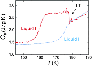 | ||
| Fig. 19 Isobaric heat capacity CP of liquid I and liquid II, measured by ac DSC measurements in the heating process (heating rate: 1 K min−1, frequency: 60 s, amplitude: 0.16 K). Stepwise changes around 157 K (liquid I) and 172 K (liquid II) are the onsets of the glass transition. Heating of liquid I induces LLT. The resulting state has the same heat capacity as a liquid state of liquid II, as expected. The figure is reproduced from Fig. 2(d) of ref. 145. | ||
Another piece of evidence supporting our scenario comes from the following fact: by combining X-ray scattering and ac DSC measurements, we confirmed that the amount of ice Ic in liquid II decreases with decreasing Ta and liquid II become less fragile (stronger) (see the supplementary information in ref. 145 for the details). In other words, the difference in the fragility between liquid I and II becomes more pronounced when liquid II contains less cubic ice. In the above-mentioned crystallization scenarios, however, after transformation the system should increase the fragility towards the fragility of pure liquid I with decreasing Ta, as a consequence of a smaller amount of cubic ice and the resulting decrease of interfacial water. Thus, these scenarios seem difficult to explain why liquid II is stronger when it contains less ice, or is more pure.
Furthermore, we analysed wide-angle X-ray scattering data for liquid I and a mixture of liquid II and cubic ice, as shown in Fig. 20 (see the supplementary information in ref. 145 for the details). This shows that although there is apparently little difference in the line shape between liquid I and liquid II, the line components obtained by the decomposition analysis are significantly different, suggesting a distinct difference in the liquid structure between them, although it may also be possible to claim that the difference comes from the presence of interfacial water.
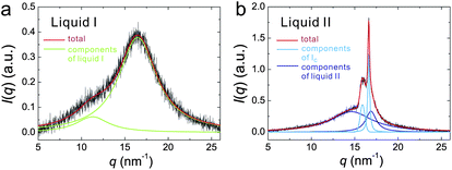 | ||
| Fig. 20 Examples of the decomposition of the wide-angle X-ray scattering spectra I(q) of liquid I and II. (a) I(q) of liquid I at 167 K (c = 0.178). The red curve is the result of the fitting for the total signal. The green curves show the Lorentzian peaks obtained by decomposing the total signal into the individual peaks. (b) I(q) of liquid II at 167 K (c = 0.178). The red curve is the result of the fitting for the total signal. The light blue curves represent the Gaussian and Lorentzian peaks from ice Ic (the Bragg peaks at 16.1 and 16.9 nm−1, respectively), whereas the dark blue curves represent those from liquid II. Please refer to the supplementary information of ref. 145 for the details of the decomposition. | ||
On the basis of the above considerations, we conclude that the transition we observe should be LLT, although further careful study may be necessary to settle this issue and form a consensus.
6 Liquid–glass transition
6.1 Our basic standpoint
In general, when a liquid is cooled, it is either crystallized or vitrified. Apart from liquids with significant quenched disorder, such as atactic polymers, a single-component liquid can in principle crystallize below the melting point Tm without any accompanying inhomogeneization (phase demixing). Glass transition is thus observed only when crystallization is ‘kinetically’ avoided. This suggests the presence of a deep link between crystallization and vitrification. Our model of glass transition is based on this physical picture.19,26,27,30–32,35 However, most previous theories of glass transition did not consider crystallization to be important for the physical description of vitrification itself. In these theories, either a purely kinetic origin for dynamic arrest is sought or the special free energy describing the vitrification branch is newly introduced. In both cases, the crystallization branch has been ignored, or purely kinetic avoidance of crystallization has been assumed. Then the main focus has been put on the origin of slow dynamics in the vitrification branch.207 This is partly because people who are interested in glass transition are not interested in the crystallization branch but only in the glass transition branch (see Fig. 7). Another reason may come from our intuition linked to a different, but related phenomenon, jamming transition. When we consider slowing down of motion of people in a packed train, we do not care about crystallization. This is also related to the fundamental question concerning the link between glass transition and jamming transition.34,35,208,209 We believe that the free energy is relevant for the description of glass transition (see Fig. 7), and thus glass transition is essentially different from jamming transition, which is purely of mechanical nature.35The above problem is also related to the most fundamental question of what is the origin of slow dynamics associated with glass transition. There are a few different scenarios: purely dynamical scenarios,210–213 scenarios based on dynamical correlations due to dense packing,214 and scenarios based on growing static order ((i) exotic amorphous order,215–219 (ii) icosahedral order,17,39,220 and (iii) spatially extendable low free-energy configurations such as crystal-like bond orientational order19,33–35,67). We are going to show that at least for weakly frustrated liquids (frustration against crystallization) glassy slow dynamics and dynamical heterogeneity are caused by the development of critical-like fluctuations of static crystal-like bond orientational order.
6.2 Roles of frustration effects on crystallization in glass-transition behaviour
Glass transition takes place if crystallization is avoided upon cooling or increasing density. However, the physical factors controlling the ease of vitrification and the nature of glass transition remain elusive. To answer these fundamental questions, we consider the phase behaviour of a system suffering from frustration effects on crystallization. There are not so many systems in which we can control the degree of frustration on crystallization in a systematic manner. As such examples, we here focus on two-types of systems: polydisperse colloidal systems and 2D spin liquids. The former suffers from random disorder effects (particle size distribution), whereas the latter from energetic frustration in the interaction potential. By comparing these two different systems, we show an intriguing scenario that the strength of frustration controls not only the ease of vitrification but also the fragility of liquid19 for both colloidal liquids221,222 and spin liquids.36,223 Despite the difference in the origin of frustration effects on crystallization (geometrical vs. energetic), the behaviour is remarkably similar between them. This implies that there is an intrinsic link between structure and dynamics in glass-forming liquids: slow dynamics may be a consequence of ‘glassy structural ordering’ towards low local free energy in a liquid.33–36,67,221 Vitrification may be a process of hidden crystal-like bond orientational (not translational) ordering under frustration19,26,27,36,67 at least for systems where crystallization is weakly frustrated.A state diagram for 2D polydisperse hard disks is shown in Fig. 21. For a monodisperse case (the polydispersity Δ = 0%), there are two sequential transitions: bond orientational ordering followed by translational ordering. Above Δ ≥ 9% (the coloured region in Fig. 21), a system starts to form glass without crystallization even for slow cooling. This shows the increase of glass-forming ability with an increase in Δ. In the glass-forming region, the fragility monotonically decreases with an increase in Δ (see Table 1).
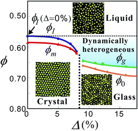 | ||
| Fig. 21 A state diagram for 2D polydisperse hard-sphere-like systems. Here ϕ is the volume fraction of colloidal particles and Δ is the degree of polydispersity, which can be regarded as the strength of frustration against crystallization. This figure is reproduced from Fig. 1 of ref. 224. | ||
| Δ 2DPC | ϕ 0 | D | Δ 3DPC | ϕ 0 | D | Δ 2DSL | T 0 | D | ||
|---|---|---|---|---|---|---|---|---|---|---|
| 9% | 0.78 | 0.24 | 6% | 0.62 | 0.70 | 0.6 | 0.099 | 7.4 | ||
| 11% | 0.81 | 0.35 | 12% | 0.65 | 1.05 | 0.65 | 0.090 | 11 | ||
| 13% | 0.82 | 0.47 | 16% | 0.67 | 1.29 | 0.7 | 0.076 | 17 | ||
| 16% | 0.83 | 0.66 | 0.75 | 0.057 | 30 | |||||
| 0.8 | 0.026 | 84 |
For this 2D system, the only source of frustration against crystallization is polydispersity Δ. This is because hexatic order is the unique bond order parameter for a particle having 6 nearest neighbours on average and this order does not suffer from any competing ordering upon its growth. We stress that bond orientational ordering in hard-sphere-like systems is a direct consequence of dense packing and a manifestation of low configurational entropy.
For a 3D polydisperse hard-sphere system, on the other hand, there are at least two origins of frustration against crystallization: one is local icosahedral ordering tendency and the other is random disorder effects originating from the size polydispersity of particles52 (see Fig. 23 below). Note that for 3D hard spheres a particle having 12 nearest neighbours can have three types of bond orientational order (fcc, hcp, and ico) (see Fig. 3). Among them, local icosahedral ordering is not a major cause of slow dynamics due to its localized nature and the dominant one is crystal-like (fcc-like) bond orientational order. This tells us that spatially extendable structural order is more responsible for slow dynamics than localized order.44 So the scenario that icosahedral ordering is a major and unique underlying ordering behind vitrification may not be valid at least for a hard sphere system. Nevertheless, local icosahedral structures are formed (see Fig. 23 below)), and their number density increases with an increase in ϕ, which leads to stronger frustration effects on crystal-like bond orientational ordering.44,45 This situation is similar to that in 2D spin liquids,36,223 where pentagons prevent crystallization (see below). In this sense, even a monodisperse hard sphere system is not free from frustration effects on crystallization and suffers from self-generated internal frustration controlled by entropy.35,45,67 This situation might be similar to metallic glass formers,28,29 although the tendency of icosahedral ordering may be more pronounced for these systems due to the chemical nature of bonding51 and the matching of atomic sizes.225
For 3D polydisperse hard-sphere systems, we also found that the increase in the polydispersity, or the strength of frustration against crystallization, leads to better glass-forming ability and a decrease in the fragility as in the case of the corresponding 2D systems (see Table 1).
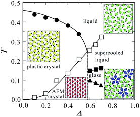 | ||
| Fig. 22 Phase diagram of 2D spin liquid in the T–Δ plane. Here Δ is a measure of the strength of frustration against crystallization, or the strength of the three-body potential favouring a locally favoured structure of five fold symmetry. Energetic frustration is caused by symmetric mismatch in the interacting potential in this system. The basic structure of the phase diagram is quite similar to that of polydisperse colloids (see Fig. 21). For small Δ, or weak frustration, the glass-forming ability is very low, whereas with an increase in the frustration strength Δ the glass-forming ability is increased and the fragility is decreased, as in the case of polydisperse colloids. This basic trend is also very much consistent with the behaviour of water under pressure and water/salt mixtures.228 This figure is reproduced from Fig. 1 of ref. 36. | ||
In this system, the strength of the frustration, which we express by Δ, controls the glass forming ability, fragility, and criticality.36,223 The state diagram is shown in Fig. 22. For small Δ, a system easily crystallizes into the plastic crystal, where spins can rotate on a hexagonal lattice. For large Δ, where the melting point of the antiferromagnetic crystal becomes higher than that of the plastic crystal, a system can be vitrified rather easily. Thus, the increase in Δ leads to the increase in the glass-forming ability. We also found that the increase in Δ decreases the fragility. This may also be due to the increase in the activation energy Ea dominating the high temperature Arrhenius regime (see section 6.5).
Applying pressure leads to the decrease in pentagons (see eqn (10) and note that Δv > 0 for a pentagon), which leads to the increase in the fragility.223 Since pressure does not alter the energy itself, this clearly indicates that the degree of frustration is a controlling factor of the fragility.
It is interesting that the number density of pentagons has a clear correlation with the growth of crystal-like bond orientational order and the fragility, indicating that pentagons disturb the growth of the correlation length of crystal-like bond orientational order.
6.3 Frustration effects on the slow dynamics of glass-forming liquids
Here we show that the disorder (or frustration) effects on crystallization controls the slow dynamics of glass-forming liquids, which is characterized by the ideal glass-transition point T0 and the fragility index D under the assumption that the structural relaxation time τα obeys the following Vogel–Fulcher–Tammann relation: τα = τ0exp(DT0/(T − T0)) or τα = τ0exp(Dϕ/(ϕ0 − ϕ)) (on the justification of T = 1/ϕ, see ref. 34). Table 1 summarizes such effects for 2D polydisperse colloids, 3D polydisperse colloids and 2D spin liquids. It tells us that the stronger the disorder effects, the lower the ideal glass-transition temperature T0, the higher the ideal-glass transition volume fraction ϕ0, and the stronger the liquid (i.e., the larger D). Despite the difference in the source of frustration and the dimensionality, the behaviour is very similar, suggesting the generality of this scenario at least on a qualitative level.6.4 Striking similarity between the above two systems
In the above we see that for both polydisperse hard spheres and 2D spin liquids, frustration against crystallization controls the glass-forming ability and the fragility: the stronger the frustration, the higher the glass-forming ability, the stronger the liquid. The phase behaviour is similar between the two systems (compare Fig. 21 and Fig. 22). Furthermore, there is the growth of bond orientational order linked to the underlying crystal structures when approaching the glass transition point. In addition, there are also competing orderings between extendable crystal-like bond orientational order and localized isolated order (icosahedral order or pentagons). The similarity in the structural features of supercooled liquid states between the two types of systems can be clearly seen in Fig. 23. The qualitative behaviour is thus the same between the two systems, despite the large difference in the interaction potential between them. This also suggests the generality of our scenario, at least for weakly frustrated systems.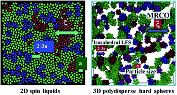 | ||
| Fig. 23 Typical structures of supercooled liquids for 2D spin liquids and 3D polydisperse colloids. We can see competing orderings between medium-range crystal-like bond orientational ordering and short-range localized ordering in both cases. | ||
6.5 Cooperative and non-cooperative origins of slow dynamics
Here we mention that even without any cooperativity or structural ordering the structural relaxation becomes slower either by lowering temperature or increasing density (or pressure). For ordinary liquids, this non-cooperative source of slow dynamics is due to the Arrhenius-type activation process, which leads to non-ergodicity only at T = 0 K. For hard-sphere liquids, on the other hand, it has a link to the jamming transition, which leads to the ergodicity breaking at the jamming point ϕJ. We emphasize that this jamming transition is a mechanical athermal transition. We argue that even for a thermal system, if there is no structural ordering, the mechanism of slowing down may be similar to the jamming transition. The situations are schematically shown in Fig. 24.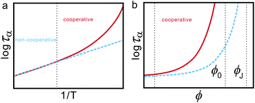 | ||
| Fig. 24 Schematic figures explaining the non-cooperative and cooperative contributions to slow dynamics for the cases of ordinary liquids (a) and hard-sphere liquids. | ||
On top of these non-cooperative sources of slow dynamics, the slowness originating from cooperativity contributes, which causes glassy slow dynamics. We proposed a possible empirical functional form describing both contributions.19,26,27,30–32,35 For example, a stronger liquid has a larger contribution from non-cooperative Arrhenius dynamics. We should always take this contribution into account when analysing slow dynamics. In the case of weakly polydisperse hard spheres, since the contribution of the non-cooperative part is not so significant in the volume fraction ϕ we can access either experimentally or numerically, we may ignore it. For highly polydisperse hard spheres, this contribution may become more important.34 Furthermore, with an increase in the spatial dimensionality d, the tendency of forming bond orientational order may become weaker since the loss of configurational entropy to gain bond orientational order steeply increases with an increase in d. This may explain why bond orientational ordering becomes less important for a system with higher d.229
We note that the presence of structural ordering in a supercooled liquid and the resulting cooperativity can be detected by the Stokes–Einstein violation. The onset of the violation is the reflection of the onset of cooperativity. The degree of the violation is stronger for a more fragile glass-forming liquid. As can be seen in hard-sphere-like liquids, the non-Arrhenius behaviour is not necessarily linked to the fragility in some liquids. Even in such cases, the Stokes–Einstein violation may be used as a finger print of cooperativity (or glassy structural ordering). For example, the Gaussian core model at a high pressure, which exhibits mean-field behaviour,209 should be regarded as a glass-forming liquid without cooperativity, although it apparently shows the non-Arrhenius behaviour.
6.6 A link between glassy structure ordering, dynamical heterogeneity, and slow glassy dynamics
The above physical picture leads us to the following scenario of slow glassy dynamics. Upon cooling, a liquid enters into a metastable state where long-range orientational and positional ordering is prohibited by frustration effects. However, bond orientational order still develops continuously towards the ideal glass transition point T0 to lower the free energy of the system. Bond orientational ordering is a manifestation of many-body correlations among strongly correlated neighbouring particles around a central particle. For a strongly disordered system, such unique bond orientational order linked to the symmetry of the equilibrium crystal may no longer exist, however, we expect that even for such a system strong correlations may still be represented by some structural signature, which has a link to low free-energy configurations of longer lifetime, namely, lower fluidity.Hereafter, we consider a case in which bond orientational order is relevant, just for simplicity. In regions of high bond orientational order, particle motion is on average slow since only the coherent motion while keeping bond orientational order is allowed. A distinct correlation between glassy structural order and slowness of particle motion can be clearly seen for a 2D polydisperse colloidal simulation in Fig. 25. We can see a similar structure-dynamics correlation for a 3D polydisperse colloid experiment in Fig. 26. As mentioned above, the length scale of the structural order, or the coherency of particle motion, is a key to the slowness of dynamics. This may also be the origin of dynamic heterogeneity.
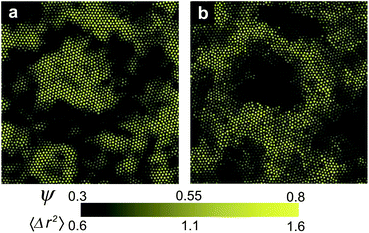 | ||
| Fig. 25 Relationship between glassy structural order and local mobility in 2DPC (ϕ = 0.740 and the polydispersity Δ = 9%). (a) The spatial distribution of the coarse-grained hexatic order parameter ψ. (b) The spatial distribution of the mean-square displacement over 10τα. We can see the almost one-to-one correspondence between highly ordered regions and regions of low mobility (or low fluidity). This figure is reproduced using a part of Fig. 1 of ref. 67. | ||
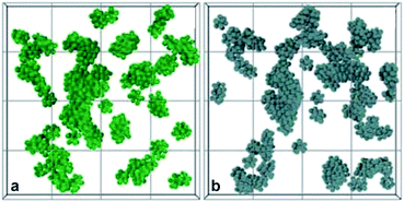 | ||
| Fig. 26 Computer reconstruction from confocal microscopy coordinates for a polydisperse colloidal suspension (ϕ = 0.575). Only particles of interest and their neighbours are displayed. The depth of the image is 12 times of diameters. Each particle is plotted with its real radius. (a) Particles having high crystal-like bond orientational order alone (the order parameter was averaged over the order of the structural relaxation time). (b) Slow particles with respect to the coarse-grained displacement. Due to particles going in and out of the field of view, assignment of particles located very near the edges of (a) and (b) were not accurate and have been removed. This figure is reproduced from a part of Fig. 4 of ref. 44. | ||
Here it may be worth noting a possible difference in the dynamic and static correlation length. In Fig. 25, we can see almost the one-to-one correspondence between static order and mobility. However, this visual comparison is affected by the color codes we employ. There is no proportionality between the static glassy structural order and the local dynamics, which is clear from a strongly nonlinear relation between them. Thus, the bare correlation length can be different between the static and dynamic ones.
Dynamic heterogeneity is an important characteristic feature in supercooled liquids.230 Now there is a consensus that there is a growing dynamic length in supercooled liquids, although it is not yet clarified whether it is the consequence or the origin of glassy slow dynamics. This length can be estimated, e.g., by bond-breakage correlations231 or by four-point density correlator.232 Recently intrinsic differences between the two methods were discussed in detail in connection with underlying vibrational motions by Onuki and his coworkers.233–235 The detailed characterization of dynamic heterogeneity including its lifetime has also been made by Kim et al.236,237 The above observation suggests that the dynamical correlation length ξ4 is comparable to the bond orientational correlation length ξ6. Thus, it may be interesting to go a step further and study a link between bond orientational order fluctuations and these new features of dynamic heterogeneity.
The increase in glassy structural order and the resulting decrease in defective structures lead to the decrease in the fluidity and thus to the slowing down of structural relaxation. Such a direct link between glassy structural ordering and slow structural relaxation dynamics is a characteristic nature of glass transition and is absent in ordinary critical phenomena. In the latter, the slowing down of the dynamics is linked to the characteristic size of the order parameter fluctuations alone, but not directly to the transport coefficient such as viscosity. For example, in a critical binary mixture, viscosity exhibits only a very weak logarithmic divergence towards a critical point.186 This suggests that a link between low free-energy configurations (bond orientational order in the systems we discuss) and local mobility (or, coherency of particle motion) is the key to glassy slow dynamics. In other words, motion of individual particles are constrained by the glassy structural order (see below).
6.7 Correlation between slow dynamics and static glassy structural order: 3D polydisperse Lennard-Jones system as an example
Here we consider the relation between slow dynamics and the correlation length of glassy structural order for a case of 3D polydisperse Lennard-Jones (LJ) system.67 A 3D polydisperse Lennard-Jones liquid (3DLJ) has been widely used to study glass-transition phenomena (see, e.g., ref. 238–242 and the references therein). We performed microcanonical (NVE) ensemble molecular dynamics (MD) simulations. The diameter of particle i is σi and the mass m is the same for all particles. Particles interact with the following Lennard-Jones potential: ULJij(r) = 4ε{(σij/r)12 − (σij/r)6 + Cij} for r < rcij where σij = (σi + σj)/2 and rcij = 2.5σij. Here Cij is a constant such that ULJij(rcij) = 0. We set the particle number N = 4096 and the particle number density ρ = N/V = 1.2. All results are shown in reduced units: length unit = 〈σ〉, temperature unit = ε/kB, and time unit = .
.
Fig. 27(a) and (b) show, respectively, the T-dependence of the intermediate scattering function F(qp,t) (qp: the peak wavenumber of the structure factor S(q)) and the structural relaxation time τα, which is determined by fitting the stretched exponential function to the slow decay of F(qp,t). By fitting VFT relation, we obtain T0 = 0.73 and D = 3.85. The T-dependence of the stretching exponent β is also plotted in Fig. 27(c). β decreases steeply upon cooling, reflecting growing dynamic heterogeneity. The bond orientational correlation function is shown in Fig. 27(d). To estimate the spatial correlation length of the bond orientational order parameter, ξ6, we calculated the spatial correlation function G6(r):
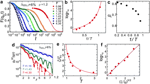 | ||
| Fig. 27 Dynamical and structural evolution upon cooling in 3D Lennard-Jones system (3DLJ). The density ρ = 1.2 and the polydispersity Δ3DLJ = 6%. (a) T-dependence of the intermediate scattering function F(qp,t). The solid curve is the stretched exponential function. (b) T-dependence of the structural relaxation time τα. It slows down more than five orders of magnitude upon cooling. The solid curve is the VFT relation. (c) T-dependence of the stretching exponent β. (d) The spatial correlation function of the bond orientational order parameter Q6, g3D6(r). The solid lines are the fittings by the 3D Ornstein–Zernike function. (e) T-dependence of the correlation length ξ. The solid curve is the power law fitting (see text). (f) The relation between τα and ξ. | ||
The decay is well described by the 3D Ornstein–Zernike function (∝ r−1exp(−r/ξ6)). Fig. 27(e) shows the T-dependence of the correlation length ξ6.
We can see that ξ = ξ6 grows as a system approaches the ideal glass-transition point T0 as ξ = ξ0[(T − T0)/T0]−2/3 with ξ0 = 3.05. The relation between τα and ξ is shown in Fig. 27(f), which indicates that τα ∝ exp[D(ξ/ξ0)3/2].
Here we present only the results of a 3D polydisperse LJ system, but the behaviour is essentially the same for 3D polydisperse hard spheres.67,222 Including 2D polydisperse hard disks,221,224 2D driven granular matter,243 and 2D spin liquids,36,223 we obtain the following general relations:67ξ = ξ0[(T − T0)/T0]−2/d and τα ∝ exp[D(ξ/ξ0)d/2], where d is the spatial dimensionality. This suggests the Ising-like criticality scenario of glass transition.35,67,70,71 The Ising-like exponent for the static correlation length was also recently reported numerically244,245 and theoretically246–248 on different grounds.
6.8 The key lengthscale for glassy slow dynamics
Here we consider what lengthscale controls the structural relaxation dynamics. There are two candidates: (i) a microscopic cage size and (ii) a mesoscopic length scale. Such a mesoscopic length may be of either static or dynamic origin. Scenario (i) is based on the physical picture that slow dynamics is due to the local caging of particles without any relevant length scale beyond the interparticle distance a. This is the schematic MCT scenario of glassy slow dynamics (or, a mean-field scenario). Other models based on a single particle picture such as hopping dynamics, energy landscape, and free volume concept belong to this category.249 On the other hand, scenario (ii) is based on the physical picture that slow dynamics is a consequence of cooperative phenomena where single particle dynamics is coherent over the length scale ξ larger than a. For example, Berthier et al.249,250 showed that the length scale marking a crossover from persistent to Fickian diffusion motion has a significant connection to slow dynamics, i.e., dynamic heterogeneity is a central aspect of the dynamics of supercooled liquids in that time and length scales are intimately connected. This is consistent with our scenario.A recent study by Furukawa and Tanaka251–253 has clearly shown that the viscous dissipation in a supercooled liquid takes place predominantly in the length scale over ξ4 (see also ref. 254, 255), which indicates the intrinsic importance of the growing mesoscopic correlation length in the viscous transport. The crossover length ξη from macroscopic to microscopic transport was found to be comparable to the dynamical correlation length ξ4. Implications of this crossover has recently been discussed by Furukawa in detail.256 Although we need to clarify whether it has a static or a kinetic origin, this study clearly indicates that the mean-field (or microscopic) mechanism may not be relevant, but the mesoscopic spatial correlation is essential to glassy slow dynamics.
The next question is then whether the mesoscopic spatial correlation is of purely kinetic or static origin. One possible scenario is based on the kinetically constrained model (see, e.g., ref. 213, 250, 257), which does not involve any static correlation but still exhibits strong dynamic correlation. Another scenario is based on the presence of static spatial correlation.67,221,222–244,258–263 The low fluidity of our glassy structural order indicates that slow dynamics may be due to the growing static correlation over ξ, which can explain the above-mentioned crossover from persistent to diffusional motion quite naturally. The point-to-set length219,229,264–271 based on the random first order transition theory12,207,216,218,272–274 is another candidate for the static lengthscale. We note that it was proven275 that if τα diverges in a super-Arrhenius manner towards a certain temperature, then ξPTS must diverge too, faster than the lower bound given by (T logτα)1/d (d: the space dimension). However, it was reported by many researchers229,248,265–267,270,276 that the static point-to-set(-like) length ξPTS is much shorter than ξ4 and the temperature dependence is different between them, that is, the static mosaic length is decoupled from the dynamical correlation length, which further means its decoupling from the characteristic length of viscous transport ξη. Since the viscous transport is the most fundamental nature, we infer that the point-to-set length may not be the relevant length scale for glassy slow dynamics. However, Szamel and his coworkers277 recently suggested a possible link between the point-to-set and dynamical lengths by combining a relation of the structural relaxation time with the dynamical correlation length ξ4 found by them and that with the point-to-set length ξPTS found by Hocky et al.267 This controversial situation might be linked to the delicateness of the estimation of the point-to-set length, or the its dependence on the pinning geometry.268,278 Interestingly, Biroli et al.279 have recently shown that the point-to-set length ξPTS estimated by the cavity method coincides with the length ξλ where the lowest eigenvalue of the Hessian matrix becomes sensitive to disorder, or plasticity. It was also suggested that τα = τ0exp(AξΨ/kBT) (1 ≤ Ψ ≤ 2), where ξ = ξPTS = ξλ and A is a constant. Although the value of Ψ is not yet determined firmly, this is not inconsistent with our scenario together with τα = τ0exp(AξΨ4/kBT) reported by Szamel and his coworkers.277 Furthermore, Mosayebi et al.244,245 estimated the static correlation length ξnad from the correlation length of the non-affine displacement field for the corresponding inherent structure of a supercooled state and found its Ising-like divergence towards T0, similar to our scenario. It is also interesting to note that their correlation length ξnad may have a connection to ξλ since the non-affine nature of deformation is linked to plasticity. We emphasize that the above-mentioned works244,245,267,277,279 commonly include results of the Kob–Andersen binary Lennards-Jones liquid. Thus, there is a chance to reveal the relationship between all these lengths. This point needs further careful study. We will discuss this problem in detail elsewhere.280
We also mention another static length called “patch correlation length”,281,282 which is also expected to be order-agnostic. This length is obtained by computing the entropy of patches of a given size R appearing in a system, which is related to the frequency of occurrence of similar structural motifs. Its usefulness was shown for 2D hard disks frustrated by a curvature of the space.282 How this works for binary systems is curious, but a possible lack of unique structural motifs for low free-energy configurations may cause a problem.
At this moment, we prefer the simplest physical scenario that there is only one relevant lengthscale, i.e., ξ6 = ξ4 = ξη (see also section 6.11.2). However, we should mention that the relation ξ6 = ξη has not been examined yet for polydisperse colloidal systems and thus there might be a possibility that there is no such a link.256
6.9 Importance of many-body correlations on slow dynamics
Here we emphasize the importance of many-body correlations in slow dynamics. Our finding suggests that slow dynamics is associated with strong correlation of particle dynamics, or coherency of motion, which originates from the many-body correlations. Thus we need to see many-body correlations to seek the structural origin of slow dynamics in a supercooled liquid.52 Bond orientational order we focus on in this article is a consequence of many-body correlations since it involves a central particle and its nearest neighbours (6 for 2D and 12 for 3D in hard spheres). Fig. 28 shows the scattering function S(q), which is the two-body density–density correlation function, and the correlation function of relevant bond orientational order parameters for both 2D and 3D polydisperse systems. We can clearly see that glassy structural order cannot be detected by S(q), but can be detected by g6(r). This also means that bond orientational ordering is completely decoupled from density field or translational ordering for hard sphere liquids. We confirm that this also holds for 2D spin liquids and 3D polydisperse Lennard-Jones liquids.67 Thus, this feature has nothing to do with whether the interaction is repulsive or attractive.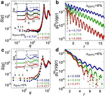 | ||
| Fig. 28 Importance of many-body correlations. (a) Scattering function S(q) for 2D polydisperse hard disks. The inset shows a wider q-range. (b) The correlation function of ψ6, g6(r), for 2D polydisperse hard disks. (c) Scattering function S(q) for 3D polydisperse hard spheres. The inset shows a wider q-range. (b) The correlation function of Q6, g6(r), for 2D polydisperse hard disks. | ||
6.10 Decoupling between bond orientational order and translational order
In the above, we showed that structural ordering in a supercooled liquid cannot be seen by the two-body density correlation. Below we seek the physical reason behind this by revealing the nature of ordering taking place in a supercooled liquid state.Here we consider the nature of crystal-like bond orientational ordering in a supercooled liquid and its decoupling with translational order, or density field. As shown above, spatial fluctuations of bond orientational ordering can be seen neither by the two-body density correlator that is a measure of translational order nor by the density field (see also ref. 52). This originates from the asymmetry in the coupling between bond orientational order and translational order (see eqn (7)). Translational ordering must accompany bond orientational ordering, but the latter needs not to accompany the former. A supercooled liquid locally takes a configuration whose rotational symmetry is related to the densest packing configuration. However, particles increase only bond orientational order without enhancement of translational order or densification. This configuration, which has an ability to become much denser yet is not dense, provides extra free volume to particles in that region and lowers local free energy (see Fig. 2). With the expense of configurational entropy associated with orientational ordering, a system gains correlational entropy. This is the case not only for hard spheres but also for systems with attractive interactions, e.g., 2D spin liquids and 3D Lennard-Jones liquids (see above). This absence of translational ordering or densification in a mesoscopic lengthscale in a supercooled state is a direct consequence of the fact that translational ordering or densification beyond a short range take place only when crystallization takes place. We stress that because of the strong first order nature of translational ordering, or crystallization, there is only weak pre-ordering in a liquid state. This also means that the loss of configurational entropy is mainly associated with the loss of bond orientational degrees of freedom. This is the reason why structural ordering cannot be detected by any scattering experiments probing the two-body density correlation function. We argue that any structural ordering in a supercooled liquid should primarily be associated with orientational ordering. This also explains why there is little change in the bulk modulus in a supercooled liquid state.
We note that this decoupling scenario applies to crystal-like bond orientational ordering, but not to locally favoured structures: for example, locally favoured structures (pentagons) formed in 2D spin liquids has a larger specific volume compared to normal liquid structures. See section 2.2 on the origin of coupling.
6.11 Origin of glassy slow dynamics: glassy critical dynamics or RFOT scenario
There are many possible explanations for slowing down of the dynamics near a glass transition point, as discussed above. Here we focus on the scenarios based on the growing static length scale. One of the currently most popular scenarios is the so-called “Random First Order Transition” (RFOT) scenario.12,207,216,218,219,272–274 Thus, we compare here our scenario with this scenario. | (25) |
![[r with combining right harpoon above (vector)]](https://www.rsc.org/images/entities/i_char_0072_20d1.gif) i} represents the atomic coordinates of a particular but generic aperiodic lattice characterized by some average density n ≡ 1/a3, where a is the average lattice spacing. The variational parameter α is a measure of localization within such a many-particle cage. Non-zero α characterizes a localized regime, whereas α = 0 represents the completely delocalized regime of the uniform liquid. Singh, Stoessel, and Wolynes283 showed that for a sufficiently high density, the RY free energy develops a metastable minimum as a function of α at the temperature TA (see also ref. 272, 273). The emergence of this minimum appears as a first order transition, where α plays the role of an order parameter, whose value changes discontinuously during the transition from zero to a non-zero value.
i} represents the atomic coordinates of a particular but generic aperiodic lattice characterized by some average density n ≡ 1/a3, where a is the average lattice spacing. The variational parameter α is a measure of localization within such a many-particle cage. Non-zero α characterizes a localized regime, whereas α = 0 represents the completely delocalized regime of the uniform liquid. Singh, Stoessel, and Wolynes283 showed that for a sufficiently high density, the RY free energy develops a metastable minimum as a function of α at the temperature TA (see also ref. 272, 273). The emergence of this minimum appears as a first order transition, where α plays the role of an order parameter, whose value changes discontinuously during the transition from zero to a non-zero value.
While the transition is first order in α, there are many distinct (both morphologically and spatially) aperiodic states randomly distributed in free energy. Thus this transition is called the “Random First Order Transition” (RFOT).215,273 Below TA a system enters into the so-called mosaic state. This TA has a link to the mode-coupling transition temperature TMCT.272 It was indicated that this situation is similar to that of the exactly soluble mean-field Potts glass, which also exhibits a dynamic transition at a temperature TA above its thermodynamic glass transition TK. It was also shown that for finite range Potts spin glasses and supercooled liquids the transition at TA would be smeared by droplet-like excitations driven by the configurational entropy.272,273 These entropic droplet excitations would provide the route to equilibration below the mean field dynamical temperature that corresponds to the mode coupling transition at TMCT. In this way, the difficulty of the mean-field mode-coupling theory that predicts an ergodic-to-nonergodic transition at TMCT ∼ TA can be removed.
As we can see in the above, the RFOT theory is constructed on the basis of the RY free energy functional, indicating that it is basically the two-body level description.
The droplet theory, constructed by balancing the entropic driving force and the opposing cost of creating an interface between glassy states with different configurations, leads to the Vogel–Fulcher–Tammann equation.218,219,274 Although this form is the same between RFOT and our scenario, the underlying physics is different. Reflecting this, the correlation length also seems to be different between them.
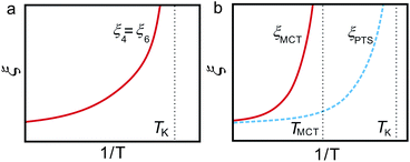 | ||
| Fig. 29 Comparison of the temperature dependence of the relevant length scale(s) in two scenarios based on the diverging static length scale: (a) our scenario and (b) the RFOT scenario. | ||
We note that, in the RFOT scenario, droplets are excitation of ‘amorphous order’, which is apparently not consistent with what we observed in weakly frustrated systems, where crystal-like (not amorphous-like) bond orientational order develops upon cooling. For this type of well-defined order, we cannot expect entropic driving force associated with a large number of amorphous configurations, which is the key to the RFOT scenario. It is not so obvious how many-body (orientational) correlations can be incorporated in the framework of the RFOT scenario. We speculate that the correlation length of RFOT, ξPTS, is primarily translational rather than orientational. In our scenario, (bond) orientational correlation is a major player. The decoupling between bond orientational order and translational order in a supercooled liquid (see above) may be related to the decoupling between ξ6 ≅ ξ4 and ξPTS, although it is a matter of controversy whether such a decoupling exists or not (see section 6.8 and ref. 277).
As noted above, we infer that the length scale picked up by the RFOT scenario has translational nature, because of the construction of the theory based on the RY free energy functional that does not include orientational correlations at least apparently. Furthermore, in our simulation and experiments, spatial fluctuations of the crystal-like bond orientational order parameter are not like ‘droplets’ but rather continuous critical-like fluctuations. Furthermore, the dynamics of the fluctuations is found to be well-described by model A type dynamics (non-conserved order-parameter dynamics).287 So the behaviour is more second-order-like rather than first-order-like. As discussed above, the point-to-set length ξPTS that is claimed to be the lengthscale of amorphous order relevant for slow glassy dynamics is always much shorter than the dynamical correlation length ξ4, which is comparable to the viscous transport crossover length ξη and the correlation length of glassy structural order (e.g., crystal-like bond orientational order) ξ. Because of the reason we mentioned above, we infer that the key length scale for glassy slow dynamics is the latter length scales (ξ4, ξη, and/or ξ) (see Fig. 29(a)).
Here we mention a piece of evidence supporting our scenario as well as its weakness. For hard spheres, the mode-coupling theory predicts that ϕMCT ∼ 0.58. However, our simulation results show that there is no divergence of the dynamical correlation length ξ4 (≅ξ6) at ϕMCT ∼ 0.58. This seems not to be consistent with the MCT–RFOT scenario (see Fig. 29(b)), although it might be ascribed to fluctuation effects. On the other hand, for binary mixtures, we have not so far succeeded in detecting a static length scale comparable to a dynamical length scale.288–290 This indicates a failure in either detecting a relevant static length scale or our scenario itself. However, it is worth noting that as discussed in section 6.8, Szamel and his coworkers277 suggests the relation ξ4 ∝ ξPTS for a few binary systems. This may be a crucial point to elucidate what is the key lengthscale responsible for glassy slow dynamics.
At this moment, we prefer to interpret glassy slow dynamics as a consequence of ‘glassy critical dynamics’,35,67,291 although further careful study is necessary to settle this problem.
6.12 Structural origin of cooperative slow dynamics
The origin of slow dynamics lies at the heart of the physics of glass transition. Our current picture on an intuitive level is as follows. Far above the glass transition point, particles move randomly and more or less independently. While approaching the glass transition point, structural order linked to low free-energy configurations develops. Because of the structural nature of this order parameter, the motion of high order regions must be strongly correlated and have a tendency to move together.Bond orientational order is not resistive to volume deformation. The susceptibility to volume deformation is rather determined by translational order. Bond orientational order is, on the other hand, resistive to transverse shear deformation. In a liquid state, there is little change in translational order, whereas bond orientational order develops when approaching the glass transition point, indicating the importance of the latter in slow dynamics. Furthermore, since shear viscosity, which diverges towards the glass transition point, is linked to the time correlation function of the shear stress tensor, it is natural to expect the important role of bond orientational order in the viscosity increase. The importance of anisotropic correlations in structural relaxation was also pointed out many years ago by Mountain and Thirumalai.292 On the microscopic level, we can say that types of particle motion that lowers the bond orientational order is not favoured. This constraint that particles in regions of high order whose characteristic length is given by ξ must move coherently may be the origin of slow dynamics, or the enhancement of the viscosity, near glass transition.
6.13 Prediction of our scenario to the glass-forming ability and the fragility of water-type liquids
In our scenario, vitrification is a consequence of frustration against crystallization. This allows us to make a qualitative prediction on the glass-forming ability and the fragility of a liquid on the basis of its phase diagram.19,26,27,30–32 This is a very unique feature of our model, which stems from the fact that we consider vitrification and crystallization on the same ground35 (see Fig. 7).Here we consider an interesting case of competing orderings, which also results in frustration against crystallization. One of the most characteristic cases belonging to this category can be seen in water-type liquids. Water has a very characteristic V-shaped T–P phase diagram (see Fig. 9). We argue that this is closely linked to the anomalies of water24 and liquids having this V-shaped phase diagram should share characteristics similar to water. By using this specific shape of the phase diagram as a fingerprint, we classified five elements Si, Ge, Sb, Bi, and Ga into water-type atomic liquids.24 Similarly, some group III–V (e.g., InSb, GaAS, and GaP) and II–VI compounds (e.g., HgTe, CdTe, and CdSe) can also be classified into water-type liquids. As described above, our model provides us with simple analytical predictions for the thermodynamic and dynamic anomalies of these water-type liquids.24
In these liquids, at low pressure, a system crystallizes into S crystal, which is favoured by bond orientational (tetrahedral) ordering. It may be worth noting that below PX there is ‘almost’ no frustration since tetrahedral locally favoured structures having a lower energy than normal liquid structures are basically compatible to S-crystal. In relation to this, it is worth noting that we recently found a weak source of frustration coming from a tendency of the increase of pentagonal rings upon cooling for water.114 Reflecting the open structure of tetrahedral order, the volume of the system expands upon crystallization of a liquid to S crystal, which leads to the negative slope of the melting point of S crystal in the T–P phase diagram. Under high pressures, a crystal into which a liquid crystallizes generally tends to have a more compact, denser structure. Thus, pressure destabilizes S-crystal and instead stabilizes ρ-crystal. Accordingly, the equilibrium crystal switches from S-crystal to ρ-crystal with increasing pressure at the crossover pressure PX. In other words, the primary order parameter responsible for crystallization into the equilibrium crystal switches from the bond order parameter S to the density order parameter ρ there, or more precisely, bond order parameters linked to ρ-crystal.
Above PX, thus, the melting point of ρ crystal becomes higher than that of S crystal. In this situation, we expect that locally favoured structures linked to tetrahedral ordering act as a source of frustration against crystallization to ρ crystal because of the mismatch between the symmetries and thus helps vitrification. We stress that the structure of the first shell is not enough to describe the locally favoured structure and that of the second shell may be necessary to specify it.114 Thus, water should tend to behave as an ordinary glass-forming liquid at very high pressures, which is consistent with the experimental indication.76,293 This tendency is difficult to explain in terms of the other existing theories of liquid–glass transition.
At low pressure, local structural ordering simply helps crystallization to S crystal, as explained above. Since an open tetrahedral structure has a specific volume larger than a normal-liquid structure, the increase in the pressure decreases the number density of locally favoured structures, i.e., ![[S with combining macron]](https://www.rsc.org/images/entities/i_char_0053_0304.gif) (see eqn (10)), which should lead to the decrease in the strength of frustration against crystallization to ρ crystal. The situation is thus very similar to the case of 2D spin liquids, where the degree of frustration also decreases with an increase in pressure,223 as discussed above. Our scenario tells us that the glass-forming ability and the fragility are positively correlated with an increase and a decrease in the degree of frustration against crystallization, respectively. We indeed confirmed this prediction for both polydisperse colloids221,222 and 2D spin liquids.36,223 Thus we predict a high glass-forming ability around the minimum of a melting curve, i.e., a triple point, for water-type liquids.23,24 This enhancement of the glass-forming ability should be more significant in the ρ-crystal side rather than in the S-crystal side. Since the frustration should stronger in the ρ-crystal side. Furthermore, in the glass-forming region, the glass-forming ability should decrease and the fragility should increase with an increase in P.
(see eqn (10)), which should lead to the decrease in the strength of frustration against crystallization to ρ crystal. The situation is thus very similar to the case of 2D spin liquids, where the degree of frustration also decreases with an increase in pressure,223 as discussed above. Our scenario tells us that the glass-forming ability and the fragility are positively correlated with an increase and a decrease in the degree of frustration against crystallization, respectively. We indeed confirmed this prediction for both polydisperse colloids221,222 and 2D spin liquids.36,223 Thus we predict a high glass-forming ability around the minimum of a melting curve, i.e., a triple point, for water-type liquids.23,24 This enhancement of the glass-forming ability should be more significant in the ρ-crystal side rather than in the S-crystal side. Since the frustration should stronger in the ρ-crystal side. Furthermore, in the glass-forming region, the glass-forming ability should decrease and the fragility should increase with an increase in P.
We confirm this scenario experimentally by using a water–LiCl mixture.228,294 In this mixture, the addition of the salt leads to the decrease in local tetrahedral order of water and the increase in hydrated structures. We confirmed this by Raman spectroscopy measurements.228,294 Thus, the salt basically acts as the breaker of locally favoured tetrahedral structures (see Fig. 30(b)), as pressure does.295Fig. 30(a) shows the phase diagram of this mixture as a function of the salt concentration ϕ, which has a V-shape similar to the T–P phase diagram of pure water (see Fig. 9). If we replace ϕ by P in the phase diagram in Fig. 30(a), it becomes essentially the same as Fig. 9. We found that the glass-forming ability becomes maximum slightly above ϕX, where the melting point has a minimum, and the fragility index D decreases with an increase in ϕ in the glass-forming region. We confirmed, from the ϕ-dependences of the viscosity and the thermodynamic driving force of crystallization which does not include the kinetic factor, that the eutectic-like deep minimum of the melting point and the resulting slow dynamics upon crystallization there alone cannot explain the enhancement of the glass-forming ability, suggesting the importance of a thermodynamic factor (energetic frustration) in glass transition. Furthermore, this conclusion is also supported by the large discrepancy between ϕX (∼12 mol%) where the viscosity at Tm has a maximum and ϕ (∼20 mol%) where the glass-forming ability becomes maximum. This discrepancy may be a consequence of the fact that local tetrahedral (S) ordering has random disorder effects only for ρ-crystal and not for S-crystal. This leads to the asymmetry of the glass-forming ability around a triple point (see above).
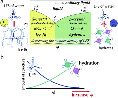 | ||
| Fig. 30 (a) Schematic phase diagram of water–LiCl mixtures.228 Locally favoured structures have a symmetry consistent with ice crystals (S-crystal), but not with hydrate crystals (ρ-crystal). In this figure, if we replace the salt concentration ϕ by pressure, it represents the phase diagram of water or other water-type liquids. Although both addition of salt and application of pressure leads to the decrease in locally favoured tetrahedral structures, their roles should have some difference since the former has local effects whereas the latter has global effects. (b) Schematic representation of the ϕ dependence of the fraction of locally favoured structures and hydration structures. Note that locally favoured structures are the source of frustration against hydrate crystals (ρ-crystal). This figure is courtesy of Mika Kobayashi. | ||
Consistent with our prediction, Molinero et al.296 succeeded in vitrifying a monoatomic Si-like liquid by weakening the tetrahedrality in the Stillinger–Weber potential in their molecular dynamics simulations: the glass-forming ability increases around the triple point between diamond cubic (dc) crystal, body centred cubic (bcc) crystal, and liquid. We note that also in this case the effect of frustration is more pronounced in the bcc crystal side rather than in the dc crystal side. Furthermore, Bhat et al.297 succeeded in experimentally obtaining a monoatomic ‘metallic’ glass of Ge at a pressure near the triple point (see also ref. 298, 299). The similar behaviour suggesting a link between crystallization and vitrification was also reported for binary Lennard-Jones mixtures.300
Our scenario provides a possibility to predict the glass-forming ability and fragility from the shape of the equilibrium phase diagram. If this is confirmed, it is a clear signature of the importance of the thermodynamics in the physical description of glass transition (see Fig. 7). The key is the relationship between global minimization of the free energy towards crystal and local minimization towards locally favoured structures. Depending upon the consistency of these two symmetries, locally favoured structures can be either a promoter of crystallization or its preventer. A physical factor making water so unusual among ‘molecular’ liquids is the V-shaped P–T phase diagram: water is only such a molecule! Instead of changing pressure, we can add additives to a liquid to modify the number density of locally favoured structures, which opens up a new possibility to control the glass-forming ability as well as the fragility of a liquid in a systematic way.
6.14 A brief summary of our scenario glass transition
In the above, we proposed that orientational ordering (or, many-body correlations) arising to lower the free energy locally leads to the constraint on particle motion and the resulting motional coherency over the characteristic length ξ, which increases the activation energy for motion and is responsible for slow dynamics associated with glass transition. We showed that such many-body correlations can be expressed by bond orientational order for weakly frustrated quasi-single-component systems. The key to vitrification is frustration against crystallization. This scenario predicts that the strength of frustration is positively correlated with the glass-forming ability and the strong nature of liquids. This prediction is unique to our model, which considers vitrification and glass transition on the same ground. Since the mechanism of glass transition is still elusive, however, further careful study is highly desirable.7 Liquid–crystal transition
7.1 Crystal nucleation from a supercooled liquid
So far we have focused on the growth of crystal-like bond orientational order in the supercooled state of a hard-sphere system. Previous theories of crystal nucleation are based on the assumption that a supercooled liquid before crystal nucleation is homogeneous (see below). However, our finding of pre-existing structural ordering in a supercooled liquid shows that this assumption is not valid. On this basis, here we consider how a supercooled liquid is destabilized against crystallization and how crystal nuclei are formed.Crystallization, or more strictly, crystal nucleation in a supercooled liquid, is a process in which a new ordered phase emerges from a disordered state. It is important not only as a fundamental problem of nonequilibrium statistical physics, but also as that of materials science.13,15,301–303 Crystallization has been basically described by the classical nucleation theory. However, nature provides intriguing ways to help crystallization beyond such a simplified picture. An important point is that the initial and final states are not necessarily the only players. This idea goes back to the step rule of Ostwald,304 which was formulated more than a century ago. He argued that the crystal phase nucleated from a liquid is not necessarily the thermodynamically most stable one, but the one whose free energy is closest to the liquid phase. Stranski and Totomanow,305 on the other hand, argued that the phase that will be nucleated should be the one that has the lowest free energy barrier. Later Alexander and McTague306 argued, on the basis of the Landau theory, that the cubic term of the Landau free energy favours nucleation of a body-centred cubic (bcc) phase in the early stage of a weak first order phase transition of a simple liquid. Since then there have been a lot of simulation studies on this problem, but with controversy (see, e.g., ref. 64, 307 and the references therein). We note that all these approaches are from the crystal side. Here we show a new scenario of crystal nucleation beyond the above classical scenarios, focusing on structural ordering intrinsic to the supercooled state of liquid. Our approach can be regarded as a new approach from the liquid side.
7.2 Density functional theory of crystallization
First we mention a phenomenological approach based on the density functional theory beyond the classical nucleation theory (see ref. 308, 309 for review).The density functional theory, which is based on the RY free energy functional, treats the solid as an inhomogeneous fluid. The starting point for a calculation of crystal nucleation rates is a Fourier expansion of ρ(![[r with combining right harpoon above (vector)]](https://www.rsc.org/images/entities/i_char_0072_20d1.gif) ) in terms of the reciprocal lattice vectors
) in terms of the reciprocal lattice vectors ![[G with combining right harpoon above (vector)]](https://www.rsc.org/images/entities/i_char_0047_20d1.gif) i:56
i:56
ρ(![[r with combining right harpoon above (vector)]](https://www.rsc.org/images/entities/i_char_0072_20d1.gif) ) = ρ ) = ρ![[small script l]](https://www.rsc.org/images/entities/char_e146.gif) [1 + μs + Σiμiexp(i [1 + μs + Σiμiexp(i![[G with combining right harpoon above (vector)]](https://www.rsc.org/images/entities/i_char_0047_20d1.gif) i· i·![[r with combining right harpoon above (vector)]](https://www.rsc.org/images/entities/i_char_0072_20d1.gif) )], )], | (26) |
![[small script l]](https://www.rsc.org/images/entities/char_e146.gif) is the mean-field homogeneous liquid density and μs is the average density change on freezing. The parameters μi are the amplitudes that describe the periodic structure in the crystal; they are zero in the liquid. The transition is thus characterized by an infinite set of order parameters μi instead of the single parameter (the average density) characterizing the gas–liquid transition. The saddle point is found as usual by minimizing the grand canonical potential functional with respect to ρ(
is the mean-field homogeneous liquid density and μs is the average density change on freezing. The parameters μi are the amplitudes that describe the periodic structure in the crystal; they are zero in the liquid. The transition is thus characterized by an infinite set of order parameters μi instead of the single parameter (the average density) characterizing the gas–liquid transition. The saddle point is found as usual by minimizing the grand canonical potential functional with respect to ρ(![[r with combining right harpoon above (vector)]](https://www.rsc.org/images/entities/i_char_0072_20d1.gif) ) with an approximation that the density can be written as as a sum of Gaussians, centred at the lattice sites of the crystal.
) with an approximation that the density can be written as as a sum of Gaussians, centred at the lattice sites of the crystal.
Oxtoby and his coworkers310,311 showed that the classical theory for the free energy of formation of the critical droplet is found to exceed that obtained in the density functional calculation. They introduced an order parameter that continuously distorts a crystal with fcc symmetry into one with bcc symmetry, to allow for the possibility that precritical bcc crystallites form first and then transform to critical fcc droplets. The latter was reported in earlier simulations of a Lennard-Jones system.64,307 Their calculation of the free energy functional showed a metastable bcc state close to the stable fcc phase. This metastable bcc phase induces a saddle point which serves as the lowest free energy barrier between the liquid and crystal, with the minimum free energy interface passing close to this saddle point. This has significant consequences for nucleation, in that a small critical droplet is largely of bcc structure at the centre and evolves into the stable fcc structure as it grows. We note that a similar framework was also applied to crystallization of hard spheres.312
The above approach has some similarity to ours in the sense that both consider the presence of at least two order parameters (density and a structural order parameter which has a link to the crystal structure). At the same time, there is a crucial difference: their order parameter is linked to translational order, whereas ours is linked not to it but to bond orientational order. For example, a supercooled liquid locally has high bond orientational order, but no translational order (μi = 0), as we have shown in section 6. In our scenario, the liquid state prior to crystal nucleation is not homogeneous but quite heterogeneous. In the density functional theory, on the other hand, it is treated as completely homogeneous: there the liquid state is simply characterized by a constant density ρ![[small script l]](https://www.rsc.org/images/entities/char_e146.gif) (see eqn (26)). Thus, we emphasize that despite the apparent similarity, the physical picture is essentially different between the two scenarios.
(see eqn (26)). Thus, we emphasize that despite the apparent similarity, the physical picture is essentially different between the two scenarios.
7.3 Formation of crystal nuclei in a polydisperse colloidal system
Before going to show the process of crystal nucleation, we discuss a link between crystal nuclei and crystal-like bond orientational order in polydisperse colloids. Fig. 31 shows regions of high crystal-like bond orientational order and crystal nuclei, which are observed in a supercooled polydisperse colloidal suspension by confocal microscopy observation. We can clearly see that crystal nuclei are always embedded in regions of high crystal-like bond orientational order. This also highlights the crucial difference between crystal-like bond orientational order with the average density and crystal order with a high local density. Since the polydispersity of this sample is high enough to avoid crystal nucleation, crystal nuclei are always smaller than the critical nucleus size and thus they have only a finite lifetime and eventually melt and disappear. However, this already suggests an intimate link between crystal-like bond orientational order formed in a supercooled liquid and crystal formation. The consistency of orientational symmetry between regions of high crystal-like bond orientational order and crystal nuclei should significantly reduce the interfacial energy between them, which promotes the formation of crystal nuclei there.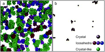 | ||
| Fig. 31 Computer reconstruction from confocal microscopy coordinates in a deeply supercooled polydisperse colloidal liquid (the polydispersity = 6%, ϕ = 0.575). Depth is ∼12σ. Only particles of interest and their neighbours are displayed. Each particle is plotted with its real radius. (a) A typical configuration of bond ordered particles. Icosahedral particles are shown in the same colour if they belong to the same cluster. If a particle is neighbouring both crystal-like and icosahedral structures, it is displayed as icosahedral. (b) Particles with more than 7 crystalline bonds. These are crystal nuclei, but their size is smaller than the critical nucleus size and thus they never grow and disappear. This figure is reproduced from a part of Fig. 4 of ref. 44. | ||
7.4 The process of crystal nucleation in a monodisperse colloidal system
Here we show a typical crystal nucleation process in a monodisperse colloidal liquid in Fig. 32. The process was observed by Brownian dynamics simulations. We can clearly see crystal nuclei are selectively formed in regions of high crystal-like bond orientational order. After a quench, thermal fluctuations of crystal-like bond orientational order are developed and this stage shows a typical behaviour of the supercooled state of a glass-forming liquid.313 In this stage very small crystal nuclei are created and annihilated in regions of high crystal-like bond orientational order, but they have a finite lifetime and are transient, as shown in Fig. 31. After some time, a nucleus whose size becomes larger than the critical nucleus size is formed and starts to grow continuously. Such a nucleus is always born selectively in a region of high crystal-like bond orientational order,313 which can be regarded as wetting effects. This is a consequence of the fact that the initial stage of crystallization is the enhancement of the spatial coherence of the phase of crystal-like bond orientational order.45 This means that crystallization is triggered by bond orientational order and not by positional order for hard-sphere liquids. Once crystals are nucleated, critical-like fluctuations of bond orientational order are pinned due to wetting to crystals.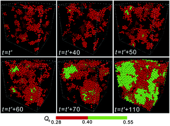 | ||
Fig. 32 Birth of crystal nuclei from medium-range structural order in 3D monodisperse hard spheres (N = 16![[thin space (1/6-em)]](https://www.rsc.org/images/entities/char_2009.gif) 384). The process of nucleation of a crystal at ϕ = 0.533. Particles with intermediate Q6 (0.28 < Q6 < 0.40) are coloured red, whereas those with high Q6 (Q6 ≥ 0.4) are coloured green. The time unit is the Brownian time of a particle, τB. We can see the birth of a crystal and its growth. t = t0 is the time when a supercooled liquid reaches a quasi-equilibrium steady state after the initiation of simulations from a random disordered state. This figure is reproduced from Fig. 2 of ref. 313. 384). The process of nucleation of a crystal at ϕ = 0.533. Particles with intermediate Q6 (0.28 < Q6 < 0.40) are coloured red, whereas those with high Q6 (Q6 ≥ 0.4) are coloured green. The time unit is the Brownian time of a particle, τB. We can see the birth of a crystal and its growth. t = t0 is the time when a supercooled liquid reaches a quasi-equilibrium steady state after the initiation of simulations from a random disordered state. This figure is reproduced from Fig. 2 of ref. 313. | ||
We also compare the two types of structural order parameters in Fig. 33. One is the coarse-grained Qi6, which is the local orientational order vector ![[q with combining macron]](https://www.rsc.org/images/entities/i_char_0071_0304.gif) i6m averaged over particle i and its surrounding,41 which we used in Fig. 32. The other is Sij = q6(i)*·q6(j) (here * means the complex conjugate) for an equilibrium and a supercooled liquid and bcc, hcp, rhcp, and fcc crystals. This parameter was used by Auer and Frenkel314 as the order parameter to characterize crystal nuclei and its kinetic pathway of crystallization. We note that both parameters are sensitive to the coherence of the phase of bond orientational order.52 We obtain almost the same results for the two order parameters, which shows the robustness of our conclusion.
i6m averaged over particle i and its surrounding,41 which we used in Fig. 32. The other is Sij = q6(i)*·q6(j) (here * means the complex conjugate) for an equilibrium and a supercooled liquid and bcc, hcp, rhcp, and fcc crystals. This parameter was used by Auer and Frenkel314 as the order parameter to characterize crystal nuclei and its kinetic pathway of crystallization. We note that both parameters are sensitive to the coherence of the phase of bond orientational order.52 We obtain almost the same results for the two order parameters, which shows the robustness of our conclusion.
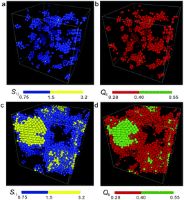 | ||
Fig. 33 Spatial distribution of order parameters for a supercooled liquid state and a liquid-crystal coexistence state. Particles coloured by the value of Sij = q6(i)*·q6(j) (a) and by the value of Q6 (b) for a supercooled liquid before nucleation (ϕ = 0.533 and N = 16![[thin space (1/6-em)]](https://www.rsc.org/images/entities/char_2009.gif) 384). Particles coloured by the value of Sij (c) and by the value of Q6 (d) for a liquid–crystal coexistence state in the same system as (a) and (b). Particles with Sij < 0.75, with 0.75 ≤ Sij < 1.5, and with Sij ≥ 1.5 appear transparent, blue and yellow, respectively, in (a) and (c). Particles with Q6 < 0.28, with 0.28 ≤ Q6 < 0.40, and with Q6 ≥ 0.40 appear transparent, red and green, respectively, in (b) and (d). 384). Particles coloured by the value of Sij (c) and by the value of Q6 (d) for a liquid–crystal coexistence state in the same system as (a) and (b). Particles with Sij < 0.75, with 0.75 ≤ Sij < 1.5, and with Sij ≥ 1.5 appear transparent, blue and yellow, respectively, in (a) and (c). Particles with Q6 < 0.28, with 0.28 ≤ Q6 < 0.40, and with Q6 ≥ 0.40 appear transparent, red and green, respectively, in (b) and (d). | ||
7.5 Our scenario of crystal nucleation
Our physical scenario of crystallization can be summarized as follows.35,45,46,313 After quenching from an equilibrium liquid state to a supercooled state, medium-range bond orientational order whose symmetry has a connection to an equilibrium crystal structure (fcc or hcp in hard-sphere colloids with more weight in fcc35,44,45) first develops as spontaneous thermal fluctuations. When high bond orientational regions have high local density as a consequence of thermal density fluctuations, crystal nucleation is initiated with a high probability by accompanying the increase in the coherence of bond orientational order without a discontinuous density jump.45 Here we note that although regions of high crystal-like bond orientational order do not have high density on average, some regions can have high density as a result of thermal density fluctuations, which allow a system to access even the lower bound density of crystals. The degree of density fluctuations is simply determined by the isothermal compressibility KT. Thus, crystal nucleation always happens in a region of a supercooled liquid simultaneously having high crystal-like bond orientational order and high density. However, we stress that a factor triggering crystal nucleation is the former and not the latter: the latter is a necessary condition, but not a sufficient condition. The sequence of crystallization from melt induced by a temperature quench is thus summarized as follows: an initial homogeneous equilibrium liquid at a high temperature is transformed into an ‘inhomogeneous’ supercooled liquid with crystal-like bond orientational order fluctuations after quenching. The phase coherency of crystal-like bond orientational order allows a system to access a high density with the help of spontaneous density fluctuations, which leads to the development of translational order (see Fig. 2 for an intuitive feeling, although the real nucleation process takes place in a larger lengthscale). Finally, a crystalline phase is formed by the development of translational order following the growth of crystal-like bond orientational order. We emphasize that these processes continuously take place at the microscopic level.Since the Ostwald's seminal argument, intermediate states between the initial liquid and the final crystal state has been searched for from the crystal side.64,304–307 However, our study demonstrates that it is crucial to consider hidden structural ordering in a supercooled liquid. We argue that the slowness of these structural fluctuations is also crucial for nucleation to efficiently take place.
7.6 Roles of bond orientational and translational ordering in crystallization of hard spheres: continuous or two-step scenario
Recently it was suggested that crystal nuclei are not formed spontaneously in one step from random fluctuations, but rather in a two step through preordered precursors of high density with structural order.315,316 This two-step crystal nucleation scenario now becomes very popular.315–321 The importance of locally high density regions as precursors was also pointed out by ref. 316 on the basis of numerical simulation of hard-sphere crystallization.Thus, we consider which of bond order parameter fluctuations and density fluctuations is crucial for crystal nucleation. We revealed that crystallization starts from crystal-like bond orientational ordering and then density ordering (positional ordering) comes into play later:45 microscopically, crystallization starts from locally high density regions inside the regions of high bond orientational order, both of which are spontaneously formed by thermal fluctuations.45 We note that density fluctuations whose amplitude is determined by isothermal compressibility KT, allow a system to locally access the lower bound of crystal density easily. Contrary to the two-step crystallization scenario, our study45 shows that a high local density is a necessary condition for crystal nucleation, but not a sufficient condition, as discussed above. On a microscopic scale it is bond order parameter and neither density nor translational order that triggers crystal nucleation. This can be seen in Fig. 34, where the ordering towards a perfect crystal takes place exclusively along the bond orientational order Q6 and not along the density ρ. The fact that the colour gradient is almost perpendicular to the ρ axis indicates that density ordering is not a driving force of crystal nucleation, at least in the early stage. As emphasized above, we note that the process of crystal nucleation in hard spheres is ‘continuous’ rather than made of ‘discrete’ steps (see Fig. 35). Our finding is markedly different from the conventional view based on macroscopic observation where we can see a discontinuous change in the density upon crystal nucleation. This clearly indicates the crucial role of bond orientational ordering in crystallization.
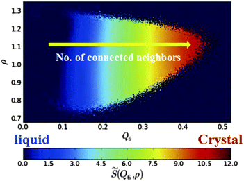 | ||
Fig. 34 Probability density for the structural order parameter ![[S with combining tilde]](https://www.rsc.org/images/entities/i_char_0053_0303.gif) in the (Q6,ρ) plane. The structural order parameter in the (Q6,ρ) plane. The structural order parameter ![[S with combining tilde]](https://www.rsc.org/images/entities/i_char_0053_0303.gif) expresses the number of connected neighbours in a continuous way (for its definition, see ref. 45). The number of connected neighbours grows continuously from 0 to 12 from the fluid to the crystal phase. This figure is reproduced from Fig. 2 of ref. 45. expresses the number of connected neighbours in a continuous way (for its definition, see ref. 45). The number of connected neighbours grows continuously from 0 to 12 from the fluid to the crystal phase. This figure is reproduced from Fig. 2 of ref. 45. | ||
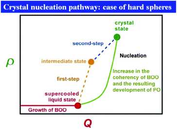 | ||
| Fig. 35 The microscopic kinetic pathway of crystal nucleation in a two-order-parameter plane. For simplicity, we consider only one type of bond orientational order Q. In reality, this process may occur in a multi-dimensional space. The two-step and the continuous scenarios of crystal nucleation are compared. According to the two-step crystallization scenario,315–321 the formation of precursors accompanies the density change from a liquid state and thus leads to a path along the ρ axis (see orange dashed line). Such behaviour was not observed in our simulations of hard spheres, at least on a mesoscopic scale.45,67,222,313 On a microscopic scale, on the other hand, there is continuous development of the coherency of crystal-like bond orientational order in high density regions, which accompanies a gradual increase in positional order (PO) and the resulting densification (see text).45 | ||
Crystal nucleation is triggered by the enhancement of the phase coherence of bond orientational order coupled to density fluctuations in a metastable liquid and then translational order follows afterwards.45 Spontaneous densification due to density fluctuations leads to the enhancement of translational order in a region where bond orientational order has phase coherence (see Fig. 2). This looks quite natural, considering that crystal nucleation starts from a very small size: it is difficult to define translational order for such a small region, since it is characterized by periodicity over a long distance. Translational order can be gradually attained in the growth process of nuclei, but not in the nucleation process. The theory of crystallization may need to be fundamentally modified to incorporate these findings. How universal this scenario is to more complex liquids remains for future investigation, but our preliminary studies on soft sphere and water suggests the generality.45,46 As we mentioned in section 2, however, for energy-driven locally favoured structures bond orientational ordering and translational ordering can be much more strongly coupled than for entropy-driven one, which may provide a crystal nucleation pathway with some variety.
7.7 Intimate link between glass transition and crystallization
In the above, we showed that (i) there is crystal-like bond orientational ordering in supercooled polydisperse colloidal liquids, which may be the origin of glassy slow dynamics and dynamical heterogeneity, and (ii) crystal nucleation is also triggered by the enhancement of the spatial coherence of this ordering. This finding strongly suggests an intimate link between crystallization and glass transition.35 Namely, a supercooled liquid is intrinsically heterogeneous and, in this sense, homogeneous nucleation may necessarily be “heterogeneous”. The state of a supercooled liquid is prepared, or self-organized, for future crystallization. This feature has been seen in the glass-forming liquids we studied: although crystal nuclei whose size exceeds the critical nucleus size are usually not formed in a good glass former, only small transient nuclei are spontaneously formed selectively in regions of high crystal-like bond orientational order44 (see Fig. 31). Frustration in crystallization controls the barrier for crystallization, and thus, plays a crucial role in the glass-forming ability. Our study suggests a necessity to develop a theory of glass transition and crystallization based on the free energy including bond orientational order (effects of many-body correlations, particularly, bond angle correlations) as an important factor in addition to translational ordering19,33–35 (see Fig. 7).7.8 A possible difference in the type of order parameter between liquid–liquid transition and liquid–crystal (glass) transition
Finally, we discuss a possible difference between the formation of locally favoured structures (local ordering) and crystal-like bond orientational order that is spatially extendable. As stressed in sections 2.2 and 6.10, the former can be coupled to the density field, but the latter cannot. More importantly, the former can be represented by the scalar order parameter S, which is the fraction of locally favoured structures, and have no orientational correlation, whereas the latter has a specific rotational symmetry associated with that of a crystal and cannot be represented by a scalar order parameter. We believe that this causes a crucial difference between the two types of phenomena, liquid–liquid transition vs. crystallization.We argue that the controversy on the presence or absence of LLT in water may be related to this issue. If the relevant order parameter is a scalar one with cooperativity, there should be liquid–liquid transition somewhere in the phase diagram. However, if the relevant order parameter is tensorial bond orientational order, its ordering leads to crystallization. If two types or order parameters coexist, which of the order parameters is more dominant may control which of LLT and crystallization takes place. Since this is speculative, we need to check carefully whether this physical picture is correct or not.
8 Summary
In this article, we have shown that any liquids have a tendency to form low free-energy configurations locally. This low free-energy configurations can often be characterized by bond orientational order, which expresses the degree of the local breakdown of the rotational symmetry.• Water's anomaly: We have shown that water anomalies can be explained solely by the temperature and pressure dependence of the fraction of locally favoured structures, whose cores have tetrahedral structures and further have translational order in the second shell.114 We have demonstrated that this fraction is proportional to the Boltzmann factor in the experimentally accessible region of the phase diagram.
• Liquid–liquid transition: We have explained liquid–liquid transition by cooperative formation of locally favoured structures. We have shown some examples of liquid–liquid transition observed in molecular liquids and discussed the controversy in the interpretation of these phenomena.
• Glass transition: We have argued that spatially extendable bond orientational order can develop in a supercooled liquid and growth of its spatio-temporal fluctuations under frustration may be the origin of glassy slow dynamics and dynamic heterogeneity at least for weakly polydisperse hard-sphere and Lennard-Jones systems and 2D spin liquids. We have proposed a scenario of glassy critical phenomena to explain the slow dynamics associated with glass transition.35,67 When the strength of frustration on crystallization is so strong that crystallization must involve phase separation, glassy order no longer has a direct link to the symmetry of the equilibrium crystal, but may still be associated with low local free-energy configurations.33–35 The validity of this physical picture is to be checked carefully for various glass-forming systems.
• Crystallization: We have shown that crystal-like bond orientational order triggers crystal nucleation with a high probability if regions of high order can reach a density required for crystallization by spontaneous thermal density fluctuations. Frustration on crystallization (polydispersity in colloidal liquids) lowers the probability of crystal nucleation significantly since it reduces the degree of crystal-like bond orientational ordering and increases the degree of icosahedral ordering which has strong frustration effects on crystallization, both of which would significantly increase the crystal–liquid interfacial energy. This strongly suggests an intrinsic link between glass transition and crystallization.
Combining these, we argue that any liquid is not a homogeneous state, but has mesoscopic or local spatio-temporal structures (see Fig. 36). We need to change our basic view of liquids and develop a theory based on the recognition that there is intrinsically a spatio-temporal hierarchical structure in liquids as in soft matter. We stress that this feature may not be captured by the standard liquid state theory, which is largely based on the two-body correlation, or translational ordering. Our study indicates the importance of many-body orientational correlations for the physical description of all these phenomena. This also suggests an encouraging possibility that all the phenomena discussed in this article can be understood on the basis of the common free energy functional (see Fig. 7), although we need to incorporate a dynamical set of equations for the description of the dynamical phenomena such as the kinetics of liquid–liquid transition, the slow dynamics associated with glass transition, and crystallization.
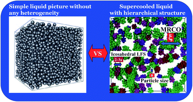 | ||
| Fig. 36 Schematic figure showing the difference between a classical picture of a liquid (the homogeneous liquid picture) and a picture based on our study (the spatio-temporally inhomogeneous liquid picture). For the latter we used a typical structure of a supercooled colloidal liquid as an example.44 | ||
Acknowledgements
First the author thanks the organizers of Faraday Discussion 167 for giving him an opportunity to present this work. He is also very grateful to M. Kobayashi for her collaboration on glass transitions in water–salt mixtures, to R. Kurita, H. Mataki, K. Murata, and R. Shimizu for their collaboration on experimental studies on liquid–liquid transitions, to T. Araki, A. Furukawa, T. Kawasaki, M. Leocmach, A. Mulins, C. P. Royall, J. Russo, H. Shintani, and K. Watanabe for their collaboration on glass transition, and to T. Kawasaki, T. Konishi, and J. Russo for their collaboration on crystallization. He also thank S. F. Edwards for his continuous encouragements from the initial stage of this work. This work was partly supported by Grants-in-Aid for Scientific Research (S) and Specially Promoted Research from JSPS and Aihara Project, the FIRST program from JSPS, initiated by CSTP.References
- J. P. Hansen and I. R. McDonald, Theory of simple liquids, Academic Press, 2006 Search PubMed.
- J. P. Boom and S. Yip, Molecular Hydrodynamics, Dover Publications, 1980 Search PubMed.
- O. Mishima and H. E. Stanley, Nature, 1998, 396, 329–335 CrossRef CAS PubMed.
- C. A. Angell, Annu. Rev. Phys. Chem., 2004, 55, 559–583 CrossRef PubMed.
- P. G. Debenedetti and H. E. Stanley, Phys. Today, 2003, 40 CrossRef CAS.
- P. G. Debenedetti, J. Phys.: Condens. Matter, 2003, 15, R1669–R1726 CrossRef CAS.
- P. H. Poole, T. Grande, C. A. Angell and P. F. McMillan, Science, 1997, 275, 322 CrossRef CAS.
- P. F. McMillan, M. Wilson, M. C. Wilding, D. Daisenberger, M. Mezouar and G. N. Greaves, J. Phys.: Condens. Matter, 2007, 19, 415101 CrossRef.
- C. A. Angell, Science, 1995, 267, 1924–1935 CAS.
- M. D. Ediger, C. A. Angell and S. R. Nagel, J. Phys. Chem., 1996, 100, 13200 CrossRef CAS.
- P. G. Debenedetti and F. H. Stillinger, Nature, 2001, 410, 259–267 CrossRef CAS PubMed.
- A. Cavagna, Phys. Rep., 2009, 476, 51–124 CrossRef CAS PubMed.
- S. P. Das, Statistical Physics of Liquids at Freezing and Beyond, Cambridge University Press, 2011 Search PubMed.
- K. Binder and W. Kob, Glassy Materials and Disordered Solids: An Introduction to Their Statistical Mechanics (Revised Edition), World Sci. Pub., 2011 Search PubMed.
- K. F. Kelton and A. L. Greer, Nucleation in Condensed Matter: Applications in Materials and Biology, Pergamon, 2010 Search PubMed.
- C. A. Angell, Chem. Rev., 2002, 102, 2627–2650 CrossRef CAS PubMed.
- D. R. Nelson, Defects and Geometry in Condensed Matter Physics, Cambridge University Press, Cambridge, 2002 Search PubMed.
- H. Tanaka, J. Phys.: Condens. Matter, 1999, 11, L159–L168 CrossRef CAS.
- H. Tanaka, J. Phys.: Condens. Matter, 1998, 10, L207–L214 CrossRef CAS.
- H. Tanaka, Phys. Rev. Lett., 1998, 80, 5750–5753 CrossRef CAS.
- H. Tanaka, Europhys. Lett., 2000, 50, 340–346 CrossRef CAS.
- H. Tanaka, J. Chem. Phys., 2000, 112, 799–809 CrossRef CAS.
- H. Tanaka, J. Phys.: Condens. Matter, 2003, 15, L703–L711 CrossRef CAS.
- H. Tanaka, Phys. Rev. B, 2002, 66, 064202 CrossRef.
- H. Tanaka, Phys. Rev. E, 2000, 62, 6968–6976 CrossRef CAS.
- H. Tanaka, J. Chem. Phys., 1999, 111, 3163–3174 CrossRef CAS.
- H. Tanaka, J. Chem. Phys., 1999, 111, 3175–3182 CrossRef CAS.
- H. Tanaka, J. Phys.: Condens. Matter, 2003, 15, L491–L498 CrossRef CAS.
- H. Tanaka, J. Non-Cryst. Solids, 2005, 351, 678–690 CrossRef CAS PubMed.
- H. Tanaka, J. Non-Cryst. Solids, 2005, 351, 3371–3384 CrossRef CAS PubMed.
- H. Tanaka, J. Non-Cryst. Solids, 2005, 351, 3385–3395 CrossRef CAS PubMed.
- H. Tanaka, J. Non-Cryst. Solids, 2005, 351, 3385–3395 CrossRef CAS PubMed.
- H. Tanaka, J. Stat. Mech., 2010, 2010, P12001 CrossRef.
- H. Tanaka, J. Phys.: Condens. Matter, 2011, 23, 284115 CrossRef PubMed.
- H. Tanaka, Eur. Phys. J. E, 2012, 35, 113 CrossRef CAS PubMed.
- H. Shintani and H. Tanaka, Nat. Phys., 2006, 2, 200–206 CrossRef CAS.
- M. Baus, J. Stat. Phys., 1987, 48, 1129–1146 CrossRef.
- P. J. Steinhardt, D. R. Nelson and M. Ronchetti, Phys. Rev. B, 1983, 28, 784–805 CrossRef CAS.
- J. F. Sadoc and R. Mosseri, Geometrical frustration, Cambridge University Press, 1999 Search PubMed.
- Z. Q. Wang and D. Stroud, J. Chem. Phys., 1990, 94, 3896–3900 CrossRef.
- W. Lechner and C. Dellago, J. Chem. Phys., 2008, 129, 114707 CrossRef PubMed.
- P. L. Chau and A. J. Hardwick, Mol. Phys., 1998, 93, 511–518 CrossRef CAS.
- J. R. Errington and P. G. Debenedetti, Nature, 2001, 409, 318–321 CrossRef CAS PubMed.
- M. Leocmach and H. Tanaka, Nat. Commun., 2012, 3, 974, DOI:10.1038/ncomms1974.
- J. Russo and H. Tanaka, Sci. Rep., 2012, 2, 505, DOI:10.1038/srep00505.
- J. Russo and H. Tanaka, Soft Matter, 2012, 8, 4206–4215 RSC.
- S. Strässler and C. Kittel, Phys. Rev., 1965, 139, A758–A760 CrossRef.
- E. Rapoport, J. Chem. Phys., 1967, 46, 2891–2895 CrossRef CAS.
- L. I. Aptekar, Soviet Physics Doklady, 1979, 24, 993–995 Search PubMed.
- F. C. Frank, Proc. R. Soc. London, Ser. A, 1952, 215, 43–46 CrossRef CAS.
- T. Tomida and T. Egami, Phys. Rev. B, 1995, 52, 3290–3308 CrossRef CAS.
- M. Leocmach, J. Russo and H. Tanaka, J. Chem. Phys., 2013, 138, 12A536 CrossRef PubMed.
- N. C. Karayiannis, R. Malshe, J. J. de Pablo and M. Laso, Phys. Rev. Lett., 2011, 83, 061505 Search PubMed.
- N. C. Karayiannis, R. Malshe, M. Kröger, J. J. de Pablo and M. Laso, Soft Matter, 2011, 8, 844–858 RSC.
- V. Holten and M. A. Anisimov, Sci. Rep., 2012, 2, 713 CrossRef CAS PubMed.
- T. V. Ramakrishnan and M. Yussouff, Phys. Rev. B, 1979, 19, 2775 CrossRef CAS.
- Y. Singh, Phys. Rep., 1991, 207, 351–444 CrossRef CAS.
- S. Hess, Z. Naturforsch. A, 1980, 35, 69–74 Search PubMed.
- A. C. Mitus and A. Z. Patashinskii, Phys. Lett., 1982, 87A, 179–182 CAS.
- A. C. Mitus and A. Z. Patashinskii, Phys. Lett., 1983, 98A, 31–34 CAS.
- J. Michalski, A. C. Mitus and A. Z. Patashinskii, Phys. Lett. A, 1987, 123, 293–296 CrossRef CAS.
- A. D. Haymet, Phys. Rev. B, 1983, 27, 1725–1731 CrossRef CAS.
- M. V. Jaríc, Phys. Rev. Lett., 1985, 55, 607–610 CrossRef.
- P. R. ten Wolde, M. J. Ruiz-Montero and D. Frenkel, Phys. Rev. Lett., 1995, 75, 2714–2717 CrossRef CAS.
- D. R. Nelson and M. Widom, Nucl. Phys. B, 1984, 240, 113–139 CrossRef.
- S. Sachdev and D. R. Nelson, Phys. Rev. B, 1985, 32, 4592 CrossRef CAS.
- H. Tanaka, T. Kawasaki, H. Shintani and K. Watanabe, Nat. Mater., 2010, 9, 324–331 CrossRef CAS PubMed.
- P. Chandra, P. Coleman and A. I. Larkin, Phys. Rev. Lett., 1990, 64, 88–91 CrossRef.
- C. Weber, L. Capriotti, G. Misguich, F. Becca, M. Elhajal and F. Mila, Phys. Rev. Lett., 2003, 91, 177202 CrossRef.
- J. S. Langer, Phys. Rev. E, 2013, 88, 012122 CrossRef CAS.
- J. S. Langer, 2013, arXiv:1308.6544.
- J. Russo and H. Tanaka, AIP Conf. Proc., 2013, 232 CrossRef CAS.
- D. Eisenberg and W. Kauzmann, The Structure and Properties of Water, Oxford University Press, 1969 Search PubMed.
- P. G. Debenedetti, Metastable Liquids: Concepts and Principles, Princeton University Press, Princeton, 1996 Search PubMed.
- A. K. Soper, Mol. Phys., 2008, 106, 2053–2076 CrossRef CAS.
- K. E. Bett and J. B. Cappi, Nature, 1965, 207, 620–621 CrossRef CAS.
- F. Caupin, A. Arvengas, K. Davitt, M. E. M. Azouzi, K. I. Shmulovich, C. Ramboz, D. A. Sessoms and A. D. Stroock, J. Phys.: Condens. Matter, 2012, 24, 284110 CrossRef PubMed.
- R. J. Speedy and C. A. Angell, J. Chem. Phys., 1976, 65, 851–858 CrossRef CAS.
- E. G. Ponyatovsky, V. V. Sinitsyn and T. A. Pozdnyakova, J. Chem. Phys., 1998, 109, 2413–2422 CrossRef CAS.
- V. Holten, C. E. Bertrand, M. A. Anisimov and J. V. Sengers, J. Chem. Phys., 2012, 136, 094507 CrossRef CAS PubMed.
- H. E. Stanley and J. Texeira, J. Chem. Phys., 1980, 73, 3404–3422 CrossRef CAS.
- S. Sastry, P. G. Debenedetti, F. Sciortino and H. E. Stanley, Phys. Rev. E, 1996, 53, 6144–6154 CrossRef CAS.
- O. Mishima and H. E. Stanley, Nature, 1998, 392, 164 CrossRef CAS PubMed.
- T. Loerting and N. Giovambattista, J. Phys.: Condens. Matter, 2006, 18, R919–R977 CrossRef CAS.
- P. H. Poole, F. Sciortino, U. Essmann and H. E. Stanley, Nature, 1992, 360, 324–328 CrossRef CAS.
- N. Giovambattista, T. Loerting, B. R. Lukanov and F. W. Starr, Sci. Rep., 2012, 2, 390 CrossRef PubMed.
- D. T. Limmer and D. Chandler, 2013, arXiv:1306.4728.
- Y. Liu, A. Z. Panagiotopoulos and P. G. Debenedetti, J. Chem. Phys., 2009, 131, 104508 CrossRef.
- P. Gallo and F. Sciortino, Phys. Rev. Lett., 2012, 109, 177801 CrossRef.
- P. H. Poole, R. K. Bowles, I. Saika-Voivod and F. Sciortino, J. Chem. Phys., 2013, 138, 034505 CrossRef PubMed.
- T. Kesselring, G. Franzese, S. Buldyrev, H. Herrmann and H. E. Stanley, Sci. Rep., 2012, 2, 474 CrossRef CAS PubMed.
- J. C. Palmer, C. Roberto and P. G. Debenedetti, Faraday Discuss., 2013, 167 10.1039/C3FD00074E.
- D. T. Limmer and D. Chandler, J. Chem. Phys., 2011, 135, 134503 CrossRef PubMed.
- D. T. Limmer and D. Chandler, J. Chem. Phys., 2013, 138, 214504 CrossRef PubMed.
- D. T. Limmer and D. Chandler, Faraday Discuss., 2013, 167 10.1039/C3FD00076A.
- K. Stokely, M. G. Mazza, H. E. Stanley and G. Franzese, Proc. Natl. Acad. Sci. U. S. A., 2010, 107, 1301–1306 CrossRef CAS PubMed.
- C. Huang, K. T. Wikfeldt, T. Tokushima, D. Nordlund, Y. Harada, U. Bergmann, M. Niebuhr, T. M. Weiss, Y. Horikawa and M. Leetmaa, et al. , Proc. Natl. Acad. Sci. U. S. A., 2009, 106, 15214 CrossRef CAS PubMed.
- A. K. Soper, J. Teixeira and T. Head-Gordon, Proc. Natl. Acad. Sci. U. S. A., 2010, 107, E44 CrossRef CAS PubMed.
- G. N. Clark, G. L. Hura, J. Teixeira, A. K. Soper and T. Head-Gordon, Proc. Natl. Acad. Sci. U. S. A., 2010, 107, 14003–14007 CrossRef CAS PubMed.
- A. Cunsolo, F. Formisano, C. Ferrero, F. Bencivenga and S. Finet, J. Chem. Phys., 2009, 131, 194502 CrossRef CAS PubMed.
- E. B. Moore and V. Molinero, J. Chem. Phys., 2009, 130, 244505 CrossRef PubMed.
- F. W. Starr, F. Sciortino and H. E. Stanley, Phys. Rev. E, 1999, 60, 6757–6768 CrossRef CAS.
- F. W. Starr, M. C. Bellissent-Funel and H. E. Stanley, Phys. Rev. E, 1999, 60, 1084–1087 CrossRef CAS.
- F. Sciortino, Chem. Phys., 2000, 258, 307–314 CrossRef CAS.
- W. K. Röntgen, Ann. Phys. U. Chim. (Wied), 1892, 45, 91–97 Search PubMed.
- G. Némethy and H. A. Scheraga, J. Chem. Phys., 1962, 36, 3382–3400 CrossRef.
- A. Ben-Naim, J. Chem. Phys., 1972, 56, 2864–2869 CrossRef CAS.
- A. Ben-Naim, J. Chem. Phys., 1972, 56, 3605–3612 CrossRef.
- C. A. Angell, J. Phys. Chem., 1971, 75, 3698–3705 CrossRef CAS.
- C. H. Cho, S. Singh and G. W. Robinson, Phys. Rev. Lett., 1996, 76, 1651–1654 CrossRef CAS.
- M. C. Bellissent-Funel, Europhys. Lett., 1998, 42, 161–166 CrossRef CAS.
- G. E. Walrafen, J. Chem. Phys., 1964, 40, 3249 CrossRef CAS.
- G. E. Walrafen, J. Chem. Phys., 1967, 47, 114–126 CrossRef CAS.
- J. Russo and H. Tanaka, 2013, arXiv:1308.4231.
- G. A. Appignanesi, J. A. Rodriguez Fris and F. Sciortino, Eur. Phys. J. E, 2009, 29, 305–310 CrossRef CAS PubMed.
- S. R. Accordino, J. A. R. Fris, F. Sciortino and G. A. Appignanesi, Eur. Phys. J. E, 2011, 34, 48 CrossRef PubMed.
- V. Holten, D. T. Limmer, V. Molinero and M. A. Anisimov, J. Chem. Phys., 2013, 138, 174501 CrossRef PubMed.
- M. J. Cuthbertson and P. H. Poole, Phys. Rev. Lett., 2011, 106, 115706 CrossRef.
- M. Matsumoto, Phys. Rev. Lett., 2010, 103, 017801 CrossRef.
- A. K. Soper and M. A. Ricci, Phys. Rev. Lett., 2000, 84, 2881 CrossRef CAS.
- S. Aasland and P. F. McMillan, Nature, 1994, 369, 633–639 CrossRef CAS.
- P. F. McMillan, M. Wilson, M. C. Wilding, D. Daisenberger, M. Mezouar and G. N. Greaves, J. Phys.: Condens. Matter, 2007, 19, 415101 CrossRef.
- P. H. Poole, T. Grande, C. A. Angell and P. F. McMillan, Science, 1997, 275, 322–324 CrossRef CAS.
- S. Harrington, R. Zhang, P. H. Poole, F. Sciortino and H. E. Stanley, Phys. Rev. Lett., 1997, 78, 2409–2412 CrossRef CAS.
- Y. Katayama, T. Mizutani, W. Utsumi, O. Shimomura and M. Yamakata, Nature, 2000, 403, 170–173 CrossRef CAS PubMed.
- Y. Katayama, Y. Inamura, T. Mizutani, M. Yamakata, W. Utsumi and O. Shimomura, Science, 2004, 306, 848–851 CrossRef CAS PubMed.
- G. Monaco, S. Falconi, W. A. Crichton and M. Mezouar, Phys. Rev. Lett., 2003, 90, 255701 CrossRef CAS.
- Y. Katayama and K. Tsuji, J. Phys.: Condens. Matter, 2003, 15, 6085–6103 CrossRef CAS.
- W. Brazhkin and A. G. Lyapin, J. Phys.: Condens. Matter, 2003, 15, 6059–6084 CrossRef.
- V. Brazhkin, Y. Katayama, M. Kondrin, T. Hattori, A. G. Lyapin and H. Saitoh, Phys. Rev. Lett., 2008, 100, 145701 CrossRef CAS.
- V. Brazhkin, M. Kanzaki, K. Funakoshi and Y. Katayama, Phys. Rev. Lett., 2009, 102, 115901 CrossRef CAS.
- S. Sastry and C. A. Angell, Nat. Mater., 2003, 2, 739–743 CrossRef CAS PubMed.
- P. Ganesh and M. Widom, Phys. Rev. Lett., 2009, 102, 075701 CrossRef CAS.
- N. Jakse and A. Pasturel, Phys. Rev. Lett., 2007, 99, 205702 CrossRef CAS.
- V. V. Vasisht, S. Saw and S. Sastry, Nat. Phys., 2011, 7, 549–553 CrossRef CAS.
- I. Brovchenko and A. Oleinikova, ChemPhysChem, 2008, 9, 2660–2675 CrossRef CAS PubMed.
- H. Tanaka, Nature, 1990, 380, 328–330 CrossRef.
- B. G. Demirjian, G. Dosseh, A. Chauty, M. L. Ferrer, D. Morineau, C. Lawrence, K. Takeda, D. Kivelson and S. Brown, J. Phys. Chem. B, 2001, 105, 2107–2116 CrossRef CAS.
- M. Mierzwa, M. Paluch, S. J. Rzoska and J. Ziolo, J. Phys. Chem. B, 2008, 112, 10383–10385 CrossRef CAS PubMed.
- R. Kurita and H. Tanaka, J. Chem. Phys., 2007, 126, 204505 CrossRef PubMed.
- K. Takae and A. Onuki, Phys. Rev. E, 2011, 83, 041504 CrossRef.
- K. Binder, Rep. Prog. Phys., 1987, 50, 783 CrossRef CAS.
- H. Tanaka, T. Yokokawa, H. Abe, T. Hayashi and T. Nishi, Phys. Rev. Lett., 1990, 65, 3136 CrossRef CAS.
- R. Kurita, K. Murata and H. Tanaka, Nat. Mater., 2008, 7, 647–652 CrossRef CAS PubMed.
- K. Murata and H. Tanaka, Nat. Mater., 2012, 11, 436–443 CrossRef CAS PubMed.
- K. Murata and H. Tanaka, Nat. Commun., 2013, 4, 2844 Search PubMed.
- E. A. Jagla, J. Chem. Phys., 1999, 111, 8980 CrossRef CAS.
- L. Xu, S. V. Buldyrev, N. Giovambattista, C. A. Angell and H. E. Stanley, J. Chem. Phys., 2009, 130, 054505 CrossRef PubMed.
- N. J. English, P. G. Kusalik, S. Tse and John, J. Chem. Phys., 2013, 139, 084508 CrossRef PubMed.
- T. Morishita, Phys. Rev. Lett., 2006, 97, 165502 CrossRef.
- P. F. McMillan, M. Wilson, D. Daisenberger and D. Machon, Nat. Mater., 2005, 4, 680–684 CrossRef CAS PubMed.
- D. Daisenberger, M. Wilson, P. F. McMillan, R. Q. Cabrera, M. C. Wilding and D. Machon, Phys. Rev. B, 2007, 75, 224118 CrossRef.
- G. N. Greaves, M. C. Wilding, S. Fearn, D. Langstaff, F. Kargl, S. Cox, Q. V. Van, O. Majérus, C. J. Benmore, R. Weber, C. M. Martin and L. Hennet, Science, 2008, 322, 566–570 CrossRef CAS PubMed.
- G. N. Greaves, M. C. Wilding, F. Kargl and L. Hennet, Adv. Mater. Res., 2008, 39–40, 3–12 CrossRef CAS PubMed.
- G. N. Greaves, M. C. Wilding, S. Fearn, F. Kargl, L. Hennet, W. Bras, O. Majérus and C. M. Martin, J. Non-Cryst. Solids, 2009, 355, 715–721 CrossRef CAS PubMed.
- L. B. Skinner, A. Barnes, P. S. Salmon and W. A. Crichton, J. Phys.: Condens. Matter, 2008, 20, 205103 CrossRef PubMed.
- A. C. Barnes, L. B. Skinner, P. S. Salmon, A. Bytchkov, I. Pozdnyakova, T. O. Farmer and H. E. Fischer, Phys. Rev. Lett., 2009, 103, 225702 CrossRef.
- O. Mishima, L. D. Calvert and E. Whalley, Nature, 1984, 310, 393 CrossRef CAS.
- E. Salcedo, A. B. de Oliveira, N. M. Barraz, C. Chakravarty and M. C. Barbosa, J. Chem. Phys., 2011, 135, 044517 CrossRef PubMed.
- H. Tanaka, R. Kurita and H. Mataki, Phys. Rev. Lett., 2004, 92, 025701 CrossRef.
- R. Kurita and H. Tanaka, Science, 2004, 306, 845–848 CrossRef CAS PubMed.
- R. Kurita and H. Tanaka, J. Phys.: Condens. Matter, 2005, 17, L293–L302 CrossRef CAS.
- A. Hédoux, Y. Guinet, M. Descamps and A. Benabou, J. Phys. Chem. B, 2000, 104, 11774–11780 CrossRef.
- A. Hédoux, P. Derollez, Y. Guinet, A. J. Dianoux and M. Descamps, Phys. Rev. B, 2001, 63, 144202 CrossRef.
- A. Hédoux, Y. Guinet, M. Foulon and M. Descamps, J. Chem. Phys., 2002, 116, 9374–9382 CrossRef.
- A. Hédoux, Y. G. amd and M. Descamps, J. Raman Spectrosc., 2001, 32, 677–688 CrossRef.
- A. Hédoux, J. Dore, Y. Guinet, M. C. Bellissent-Funel, D. Prevost, M. Descamps and D. Grandjean, Phys. Chem. Chem. Phys., 2002, 4, 5644–5648 RSC.
- A. Hédoux, Y. Guinet and M. Descamps, Phys. Rev. B, 1998, 58, 31–34 CrossRef.
- A. Hédoux, Y. Guinet, M. Descamps and A. Bénabou, J. Phys. Chem., 2000, 104, 11774–11780 Search PubMed.
- I. M. Shmyt'ko, R. J. Jiménez-Riobóo, M. Hassaine and M. A. Ramos, J. Phys.: Condens. Matter, 2010, 22, 195102 CrossRef CAS PubMed.
- M. Hassaine, R. J. Jiménez-Riobóo, I. V. Sharapova, O. A. Korolyuk, A. I. Krivchikov and M. A. Ramos, J. Chem. Phys., 2009, 131, 174508 CrossRef PubMed.
- A. I. Krivchikov, M. Hassaine, I. V. Sharapova, O. A. Korolyuk, R. J. Jiménez-Riobûo and M. A. Ramos, J. Non-Cryst. Solids, 2011, 357, 524–529 CrossRef CAS PubMed.
- H. K. Lee and R. H. Swendsen, Phys. Rev. B, 2001, 64, 214102 CrossRef.
- G. Franzese, M. Marqués and H. E. Stanley, Phys. Rev. E, 2003, 67, 011103 CrossRef.
- G. Franzese, G. Malescio, A. Skibinsky, S. V. Buldyrev and H. E. Stanley, Phys. Rev. E, 2002, 66, 051206 CrossRef CAS.
- G. Franzese and H. E. Stanley, J. Phys.: Condens. Matter, 2007, 19, 205126–295141 CrossRef.
- A. Ha, I. Cohen, X. Zhao, M. Lee and D. Kivelson, J. Phys. Chem., 1996, 100, 1–4 CrossRef CAS.
- I. Cohen, A. Ha, X. Zhao, M. Lee, T. Fisher, M. J. Strouse and D. Kivelson, J. Phys. Chem., 1996, 100, 8518–8526 CrossRef CAS.
- J. Wiedersich, A. Kudlik, J. Gottwald, G. Benini, I. Roggatz and E. Rössler, J. Phys. Chem. B, 1997, 101, 5800–5803 CrossRef CAS.
- S. Dvinskikh, G. Benini, J. Senker, M. Vogel, J. Wiedersich, A. Kudlik and E. Rössler, J. Phys. Chem. B, 1999, 103, 1727–1737 CrossRef CAS.
- J. Senker and E. Rössler, J. Phys. Chem. B, 2002, 106, 7592–7595 CrossRef CAS.
- M. Mizukami, K. Kobashi, M. Hanaya and M. Oguni, J. Phys. Chem. B, 1999, 103, 4078–4088 CrossRef CAS.
- C. Alba-Simionesco and G. Tarjus, Europhys. Lett., 2000, 52, 297–303 CrossRef CAS.
- G. Johari and C. Ferrari, J. Phys. Chem. B, 1997, 101, 10191–10197 CrossRef CAS.
- B. E. Schwickert, S. R. Kline, H. Zimmermann, K. M. Lantzky and J. L. Yarger, Phys. Rev. B, 2001, 64, 045410 CrossRef.
- A. Onuki, Phase Transition Dynamics, Cambridge University Press, Cambridge, 2002 Search PubMed.
- M. A. Anisimov, Private communication.
- R. Kurita, Y. Shinohara, Y. Amemiya and H. Tanaka, J. Phys.: Condens. Matter, 2007, 19, 152101–152108 CrossRef.
- R. Kurita and H. Tanaka, Phys. Rev. Lett., 2005, 95, 065701 CrossRef.
- K. Murata and H. Tanaka, Nat. Commun., 2010, 1, 16, DOI:10.1038/ncomms1015.
- L. Liu, S. H. Chen, A. Faraone, C. W. Yen and C. Y. Mou, Phys. Rev. Lett., 2005, 95, 117802–117805 CrossRef.
- F. Mallamace, C. Branca, M. Broccio, C. Corsaro, N. Gonzalez-Segredo, J. Spooren, H. E. Stanley and S. H. Chen, Eur. Phys. J. E, 2008, 161, 19–33 Search PubMed.
- W. Doster, S. Busch, A. M. Gaspar, M.-S. Appavou, J. Wuttke and H. Scheer, Phys. Rev. Lett., 2010, 104, 098101–098104 CrossRef CAS.
- R. Mancinelli, J. Phys.: Condens. Matter, 2010, 22, 404213 CrossRef CAS PubMed.
- D. Morineau and C. Alba-Simionesco, J. Phys. Chem. Lett., 2010, 1, 1155–1159 CrossRef CAS.
- G. H. Findenegg, S. Jähnert, D. Akcakayiran and A. Schreiber, ChemPhysChem, 2008, 9, 2651–2659 CrossRef CAS PubMed.
- A. Taschin, P. Bartolini, A. Marcelli, R. Righinia and R. Torre, Faraday Discuss., 2013, 167 10.1039/C3FD00060E.
- L. B. Lane, Ind. Eng. Chem., 1925, 17, 924 CrossRef CAS.
- J. J. Towey, A. K. Soper and L. Dougan, Faraday Discuss., 2013, 167 10.1039/C3FD00084B.
- J. J. Towey and L. Dougan, J. Phys. Chem. B, 2012, 116, 1633–1641 CrossRef CAS PubMed.
- K. L. Ngai, Relaxation and Diffusion in Complex Systems, Springer Verlag, 2011 Search PubMed.
- R. Kurita and H. Tanaka, Phys. Rev. B, 2006, 73, 104202 CrossRef.
- K. Murata and H. Tanaka, to be published.
- A. Hédoux, O. Hernandez, J. Lefebvre, Y. Guinet and M. Descamps, Phys. Rev. B, 1999, 60, 9390 CrossRef.
- Y. Hayashi, A. Puzenko and Y. Feldman, J. Phys. Chem. B, 2005, 109, 16979–16981 CrossRef CAS PubMed.
- Y. Hayashi, A. Puzenko, I. B. anf, Y. E. Ryabov and Y. Feldman, J. Phys. Chem. B, 2005, 109, 9174–9177 CrossRef CAS PubMed.
- L. Berthier and G. Biroli, Rev. Mod. Phys., 2011, 83, 587 CrossRef CAS.
- A. J. Liu and S. R. Nagel, Annu. Rev. Condens. Matter Phys., 2010, 1, 347–369 CrossRef PubMed.
- A. Ikeda and K. Miyazaki, Phys. Rev. Lett., 2011, 106, 15701 CrossRef.
- F. Ritort and P. Sollich, Adv. Phys., 2003, 52, 219–342 CrossRef.
- G. H. Fredrickson and H. C. Andersen, Phys. Rev. Lett., 1984, 53, 1244–1247 CrossRef.
- M. Merolle, J. P. Garrahan and D. Chandler, Proc. Natl. Acad. Sci. U. S. A., 2005, 102, 10837 CrossRef CAS PubMed.
- L. O. Hedges, R. L. Jack, J. P. Garrahan and D. Chandler, Science, 2009, 323, 1309 CrossRef CAS PubMed.
- W. Götze, Complex Dynamics of Glass-Forming Liquids: A Mode-Coupling Theory, Oxford University Press, Oxford, 2009 Search PubMed.
- T. R. Kirkpatrick, D. Thirumalai and P. G. Wolynes, Phys. Rev. A, 1989, 111, 1045–1054 CrossRef.
- G. Parisi and F. Zamponi, Rev. Mod. Phys., 2010, 82, 789–845 CrossRef.
- X. Xia and P. G. Wolynes, Proc. Natl. Acad. Sci. U. S. A., 2000, 97, 2990–2994 CrossRef CAS.
- V. Lubchenko and P. G. Wolynes, Annu. Rev. Phys. Chem., 2007, 58, 235–266 CrossRef CAS PubMed.
- G. Biroli and J.-P. Bouchaud, Struct. Glasses Supercooled Liq., 2012, 31–113 CrossRef.
- G. Tarjus, S. A. Kivelson, Z. Nussinov and P. Viod, J. Phys.: Condens. Matter, 2005, 17, R1143–R1182 CrossRef CAS.
- T. Kawasaki, T. Araki and H. Tanaka, Phys. Rev. Lett., 2007, 99, 215701 CrossRef.
- T. Kawasaki and H. Tanaka, J. Phys.: Condens. Matter, 2010, 22, 232102 CrossRef PubMed.
- H. Shintani and H. Tanaka, Nat. Mater., 2008, 7, 870–877 CrossRef CAS PubMed.
- T. Kawasaki and H. Tanaka, J. Phys.: Condens. Matter, 2011, 23, 194121 CrossRef PubMed.
- M. Shimono and H. Onodera, Rev. Metall., 2012, 109, 41–46 CrossRef CAS PubMed.
- V. Ilyin, E. Lerner, T. Lo and I. Procaccia, Phys. Rev. Lett., 2007, 99, 135702 CrossRef.
- E. Lerner, I. Procaccia and I. Regev, Phys. Rev. E, 2009, 79, 031501 CrossRef.
- M. Kobayashi and H. Tanaka, Phys. Rev. Lett., 2011, 106, 125703 CrossRef.
- B. Charbonneau, P. Charbonneau and G. Tarjus, J. Chem. Phys., 2013, 138, 12A515 CrossRef PubMed.
- L. Berthier, G. Biroli, J. P. Bouchaud, L. Cipelletti and W. van Saarloos, Dynamical heterogeneities in glasses, colloids, and granular media, Oxford University Press, 2011, vol. 150 Search PubMed.
- R. Yamamoto and A. Onuki, Phys. Rev. E, 1998, 58, 3515 CrossRef CAS.
- N. Lačević, F. W. Starr, T. B. Schroder and S. C. Glotzer, J. Chem. Phys., 2003, 119, 7372–7387 CrossRef.
- H. Shiba, T. Kawasaki and A. Onuki, Phys. Rev. E, 2012, 86, 041504 CrossRef.
- T. Kawasaki and A. Onuki, J. Chem. Phys., 2013, 138, 12A514 CrossRef PubMed.
- T. Kawasaki and A. Onuki, Phys. Rev. E, 2013, 87, 012312 CrossRef.
- K. Kim and S. Saito, J. Chem. Phys., 2010, 133, 044511 CrossRef PubMed.
- K. Kim and S. Saito, J. Chem. Phys., 2013, 138, 12A506 Search PubMed.
- N. Kiriushcheva and P. H. Poole, Phys. Rev. E, 2001, 65, 011402 CrossRef.
- R. K. Murarka and B. Bagchi, Phys. Rev. E, 2003, 67, 051504 CrossRef.
- S. E. Abraham, S. M. Bhattacharrya and B. Bagchi, Phys. Rev. Lett., 2008, 100, 167801 CrossRef.
- S. E. Abraham and B. Bagchi, Phys. Rev. E, 2008, 78, 051501 CrossRef.
- F. Leonforte, R. Boissiére, A. Tanguy, J. P. Wittmer and J. L. Barrat, Phys. Rev. B, 2005, 72, 224206 CrossRef.
- K. Watanabe and H. Tanaka, Phys. Rev. Lett., 2008, 100, 158002 CrossRef.
- M. Mosayebi, E. Del Gado, P. Ilg and H. C. Öttinger, Phys. Rev. Lett., 2010, 104, 205704 CrossRef.
- M. Mosayebi, E. Del Gado, P. Ilg and H. C. Öttinger, J. Chem. Phys., 2012, 137, 024504 CrossRef PubMed.
- S. Yaida, 2012, arXiv:1212.0857.
- E. Dyer, J. Lee and S. Yaida, 2013, arXiv:1302.2917.
- E. Dyer, J. Lee and S. Yaida, 2013, arXiv:1309.5085.
- L. Berthier, Phys. Rev. E, 2004, 69, 020201 CrossRef.
- L. Berthier, D. Chandler and J. P. Garrahan, Europhys. Lett., 2005, 69, 320 CrossRef CAS.
- A. Furukawa and H. Tanaka, Phys. Rev. Lett., 2009, 103, 135703 CrossRef.
- A. Furukawa and H. Tanaka, Phys. Rev. E, 2011, 84, 061503 CrossRef.
- A. Furukawa and H. Tanaka, Phys. Rev. E, 2012, 86, 030501 CrossRef.
- J. Kim and T. Keyes, J. Phys. Chem. B, 2005, 109, 21445–21448 CrossRef CAS PubMed.
- R. M. Puscasu, B. D. Todd, P. J. Daivis and J. S. Hansen, J. Chem. Phys., 2010, 133, 144907 CrossRef CAS PubMed.
- A. Furukawa, Phys. Rev. E, 2013, 87, 062321 CrossRef.
- J. P. Garrahan and D. Chandler, Proc. Natl. Acad. Sci. U. S. A., 2003, 100, 9710–9714 CrossRef CAS PubMed.
- A. Widmer-Cooper, P. Harrowell and H. Fynewever, Phys. Rev. Lett., 2004, 93, 135701 CrossRef.
- A. Widmer-Cooper and P. Harrowell, J. Phys.: Condens. Matter, 2005, 17, S4025–S4034 CrossRef CAS.
- F. Sausset and G. Tarjus, Phys. Rev. Lett., 2010, 104, 065701 CrossRef.
- A. Widmer-Cooper, H. Perry, P. Harrowell and D. R. Reichman, Nat. Phys., 2008, 4, 711–715 CrossRef CAS.
- A. Widmer-Cooper, H. Perry, P. Harrowell and D. R. Reichman, J. Chem. Phys., 2009, 131, 194508 CrossRef PubMed.
- D. Coslovich, Phys. Rev. E, 2011, 83, 051505 CrossRef.
- J. P. Bouchaud and G. Biroli, J. Chem. Phys., 2004, 121, 7347 CrossRef CAS PubMed.
- W. Kob, S. Roldán-Vargas and L. Berthier, Nat. Phys., 2011, 8, 164–167 CrossRef.
- G. Biroli, J. P. Bouchaud, A. Cavagna, T. S. Grigera and P. Verrochio, Nat. Phys., 2008, 4, 771–775 CrossRef CAS.
- G. M. Hocky, T. E. Markland and D. R. Reichman, Phys. Rev. Lett., 2012, 108, 225506 CrossRef.
- L. Berthier and W. Kob, Phys. Rev. E, 2012, 85, 011102 CrossRef.
- C. Cammarota and G. Biroli, Proc. Natl. Acad. Sci. U. S. A., 2012, 109, 8850–8855 CrossRef PubMed.
- P. Charbonneau and G. Tarjus, Phys. Rev. E, 2013, 87, 042305 CrossRef.
- S. Karmakar and G. Parisi, Proc. Natl. Acad. Sci. U. S. A., 2013, 110, 2752–2757 CrossRef CAS PubMed.
- T. R. Kirkpatrick and D. Thirumalai, J. Phys. A, 1989, 22, L149–L155 CrossRef.
- T. R. Kirkpatrick and D. Thirumalai, Phys. Rev. B, 1987, 36, 5388 CrossRef.
- T. R. Kirkpatrick and D. Thirumalai, Struct. Glasses Supercooled Liq., 2012, 223 CrossRef.
- A. Montanari and G. Semerjian, J. Stat. Phys., 2006, 125, 23–54 CrossRef.
- A. J. Dunleavy, K. Wiesner and C. P. Royall, Phys. Rev. E, 2012, 86, 041505 CrossRef.
- E. Flenner, H. Staley and G. Szamel, 2013, arXiv:1310.1029.
- G. Szamel and E. Flenner, Europhys. Lett., 2013, 101, 66005 CrossRef CAS.
- G. Biroli, S. Karmakar and I. Procaccia, Phys. Rev. Lett., 2013, 111, 165701 CrossRef.
- J. Russo and H. Tanaka, to be published.
- J. Kurchan and D. Levine, J. Phys. A: Math. Theor., 2011, 44, 035001 CrossRef.
- F. Sausset and D. Levine, Phys. Rev. Lett., 2011, 107, 045501–045501 CrossRef.
- Y. Singh, J. P. Stoessel and P. G. Wolynes, Phys. Rev. Lett., 1985, 54, 1059–1062 CrossRef CAS.
- P. Chaudhuri, S. Karmakar and C. Dasgupta, Phys. Rev. Lett., 2008, 100, 125701 CrossRef.
- B. Charbonneau, P. Charbonneau and G. Tarjus, Phys. Rev. Lett., 2012, 108, 35701 CrossRef.
- C. Cammarota, G. Gradenigo and G. Biroli, 2013, arXiv:1305.3538.
- P. C. Hohenberg and B. I. Halperin, Rev. Mod. Phys., 1976, 49, 435–479 CrossRef.
- A. Malins, J. Eggers, C. P. Royall, S. R. Williams and H. Tanaka, 2012, arXiv:1203.1732.
- A. Malins, J. Eggers, C. P. Royall, S. R. Williams and H. Tanaka, J. Chem. Phys., 2013, 138, 12A535 CrossRef PubMed.
- A. Malins, J. Eggers, H. Tanaka and C. P. Royall, Faraday Discuss., 2013, 167 10.1039/C3FD00078H.
- D. S. Fisher, J. Appl. Phys., 1987, 61, 3672–3677 CrossRef.
- R. D. Mountain and D. Thirumalai, J. Chem. Phys., 1990, 92, 6116 CrossRef CAS.
- E. W. Lang and H. D. Lüdemann, Angew. Chem., Int. Ed. Engl., 1982, 21, 315–388 CrossRef.
- M. Kobayashi and H. Tanaka, J. Phys. Chem. B, 2011, 115, 14077–14090 CrossRef CAS PubMed.
- R. Leberman and A. K. Soper, Nature, 1995, 378, 364–366 CrossRef CAS.
- V. Molinero, S. Sastry and C. A. Angell, Phys. Rev. Lett., 2006, 97, 075701 CrossRef.
- M. H. Bhat, V. Molinero, E. Soignard, V. C. Solomon, S. Sastry, J. L. Yarger and C. A. Angell, Nature, 2007, 448, 787–790 CrossRef CAS PubMed.
- F. X. Zhang and W. K. Wang, Phys. Rev. B, 1995, 52, 3113–3116 CrossRef CAS.
- D. W. He, F. X. Zhang, W. Yu, M. Zhang, Y. P. Liu and W. K. Wang, J. Appl. Phys., 1998, 83, 5003 CrossRef CAS.
- A. Banerjee, S. Chakrabarty and S. M. Bhattacharyya, J. Chem. Phys., 2013, 139, 104501 CrossRef PubMed.
- S. Auer and D. Frenkel, Adv. Polym. Sci., 2005, 173, 149–207 CrossRef CAS.
- R. Sear, J. Phys.: Condens. Matter, 2007, 19, 033101 CrossRef.
- U. Gasser, J. Phys.: Condens. Matter, 2009, 21, 203101 CrossRef CAS PubMed.
- W. Ostwald, Z. Phys. Chem., 1897, 22, 289–330 CAS.
- N. I. Stranski and D. Totomanow, Z. Phys. Chem., 1933, 163, 399–408 Search PubMed.
- S. Alexander and J. P. McTague, Phys. Rev. Lett., 1978, 41, 702–705 CrossRef CAS.
- P. R. ten Wolde, M. J. Ruiz-Montero and D. Frenkel, J. Chem. Phys., 1996, 104, 9932–9947 CrossRef CAS.
- D. W. Oxtoby, Acc. Chem. Res., 1998, 31, 91 CrossRef CAS.
- J. D. Gunton, J. Stat. Phys., 1999, 95, 903–923 CrossRef.
- C. K. Bagdassarian and D. W. Oxtoby, J. Chem. Phys., 1994, 100, 2139 CrossRef CAS.
- Y. C. Shen and D. W. Oxtoby, J. Chem. Phys., 1996, 105, 6517 CrossRef CAS.
- L. Gránásy, T. Pusztai, G. Tóth, Z. Jurek, M. Conti and B. Kvamme, J. Chem. Phys., 2003, 119, 10376 CrossRef.
- T. Kawasaki and H. Tanaka, Proc. Natl. Acad. Sci. U. S. A., 2010, 107, 14036–14041 CrossRef CAS PubMed.
- S. Auer and D. Frenkel, Nature, 2001, 409, 1020–1023 CrossRef CAS PubMed.
- J. F. Lutsko and G. Nicolis, Phys. Rev. Lett., 2006, 96, 46102 CrossRef.
- T. Schilling, H. J. Schöpe, M. Oettel, G. Opletal and I. Snook, Phys. Rev. Lett., 2010, 105, 025701 CrossRef CAS.
- H. J. Schöpe, G. Bryant and W. van Megen, Phys. Rev. Lett., 2006, 96, 175701 CrossRef.
- J. R. Savage and A. D. Dinsmore, Phys. Rev. Lett., 2009, 102, 198302 CrossRef CAS.
- S. Iacopini, T. Palberg and H. J. Schöpe, J. Chem. Phys., 2009, 130, 084502 CrossRef PubMed.
- B. OfMalley and I. Snook, J. Chem. Phys., 2005, 123, 054511 CrossRef PubMed.
- W. Lechner, C. Dellago and P. G. Bolhuis, Phys. Rev. Lett., 2011, 106, 85701 CrossRef.
| This journal is © The Royal Society of Chemistry 2013 |


