
 Open Access Article
 This Open Access Article is licensed under a
 Creative Commons Attribution 3.0 Unported Licence
Hydrogen bubble evolution and its induced mass transfer on zinc electrodes in alkaline and neutral media
Yi
He
a,
Yongfu
Liu
b,
Wenxu
Shang
*c and
Peng
Tan
 *ad
*ad
aDepartment of Thermal Science and Energy Engineering, University of Science and Technology of China, Hefei 230026, Anhui, China
bSchool of Intelligent Manufacturing, Huzhou College, Huzhou 313000, Zhejiang, China
cNational Key Laboratory of Deep Space Exploration, Hefei, 230000, China. E-mail: wxshang@mail.ustc.edu.cn
dState Key Laboratory of Fire Science, University of Science and Technology of China, Hefei 230026, Anhui, China. E-mail: pengtan@ustc.edu.cn
First published on 5th March 2025
Abstract
The evolution of hydrogen bubbles plays a critical role in governing the performance of Zn-based batteries by influencing Zn deposition, electrode morphology, and mass transfer dynamics. This work consolidates recent progress in understanding the dual influence of hydrogen bubble evolution on Zn-based batteries, emphasizing its implications for mass transfer and electrochemical performance. While presenting challenges such as inhomogeneous Zn deposition, dendrite formation, and Zn passivation, hydrogen bubble evolution simultaneously facilitates mass transfer through its forced convective disturbance. Advanced experimental techniques, including electrochemical mass spectrometry, X-ray microscopy, and gas chromatography, are employed to investigate the complex interplay between the hydrogen evolution reaction (HER) and Zn deposition. The hydrogen bubbles induced by the HER not only promote local convection to enhance the transport of zincate or Zn ions but also serve as templates for forming porous Zn structures to increase the electrochemically active surface area and accelerate reaction kinetics. Finally, emerging strategies are explored to mitigate the detrimental effects of the HER, while capitalizing on its beneficial properties to optimize Zn electrode performance, with the ultimate goal of improving the efficiency, safety, and longevity of rechargeable Zn-based energy storage devices.
1. Introduction
Li-ion batteries (LIBs) have long dominated the landscape of electrochemical energy storage due to their reliability and high energy density.1,2 However, safety concerns and the finite availability of lithium resources increasingly challenge their long-term sustainability.3,4 These limitations have prompted intensive research into alternative systems that are both safer and more sustainable.5,6 Among these, rechargeable Zn-based batteries, including Zn–air, Zn–Ni, and Zn–Ag batteries with alkaline electrolytes, as well as Zn-ion batteries with neutral or mildly acidic electrolytes, have emerged as compelling candidates.5,7,8 Zn-based systems offer intrinsic safety, cost-effectiveness, and environmental benefits, underpinned by the advantageous properties of Zn metal.9 Historically a cornerstone in primary battery technologies, Zn metal stands out for its abundance and its compatibility with aqueous electrolytes, which contrast sharply with the challenges of metallic Li.10–13 Notably, the theoretical energy density of Zn–air batteries (1080 W h kg−1) is nearly three times that of LIBs, positioning them as particularly attractive for portable and mobile applications.14–16Despite their promise, Zn-based batteries face critical challenges in achieving high reversibility, primarily due to the thermodynamic instability of the Zn metal anode in aqueous electrolytes.17–19 This instability manifests as dendritic growth, passivation, and the hydrogen evolution reaction (HER) at the electrode–electrolyte interface, significantly impairing battery performance.20,21 The HER, in particular, competes with Zn electrodeposition and generates hydrogen gas, leading to bubble formation and battery swelling.22,23 These effects not only lower coulombic efficiency but also complicate the electrodeposition process by altering the interfacial dynamics.
Traditional studies have primarily focused on Zn electrodeposition mechanisms, and the interplay between the HER and Zn electrodeposition has been largely overlooked.24 The electrochemical reactions involved are summarized below:25–27
• Alkaline electrolyte:
| 2H2O + 2e− → H2 + 2OH− | (1) |
| [Zn(OH)4]2− + 2e− → Zn + 4OH− | (2) |
• Neutral electrolyte:
| 2H+ + 2e− → H2 | (3) |
| Zn2+ + 2e− → Zn | (4) |
Furthermore, while electrolyte convection − both natural and forced − has been recognized as an important factor influencing Zn electrodeposition, the role of hydrogen bubble dynamics in this context remains insufficiently understood.28–31 Hydrogen bubble evolution not only reduces the effective surface area for Zn deposition but also induces forced convection, potentially enhancing mass transfer. This dual role introduces a complex interplay that warrants deeper analysis.
In this review, we critically examine the role of hydrogen bubble evolution in Zn-based batteries, particularly its influence on mass transfer and Zn electrodeposition in both alkaline and neutral electrolytes. We aim to elucidate how HER-induced phenomena affect Zn deposition and passivation, providing a comprehensive framework to understand these interactions. Additionally, we highlight the potential benefits of bubble-induced mass transfer enhancement and discuss innovative strategies to harness this behavior for high-performance battery designs. By consolidating recent progress and exploring future directions, this work seeks to inspire new ideas and methodologies to advance the industrialization of Zn-based energy storage technologies.
2. Mass transfer impact of hydrogen bubble evolution on Zn electrodes
Efficient mass transport between the electrode surface and the bulk electrolyte is crucial for the electrochemical performance of rechargeable Zn-based batteries. Mass transfer occurs through three fundamental mechanisms in this diluted solution: diffusion, electromigration, and convection.9,32,33 Diffusion arises from concentration gradients, while electromigration is driven by electric field gradients. Convection, in contrast, results from external or internal forces acting on the electrolyte, encompassing natural convection (driven by temperature, density, or gravitational differences) and forced convection (arising from external flows or bubble evolution).In Zn-based batteries where diluted solution is used, mass transfer primarily relies on diffusion and convection to move zincate or Zn ions (Fig. 1).9 During Zn plating, solvated ions migrate to the electrode, desolvate, and deposit as metallic Zn. The combined mass transport flux is governed by the Nernst–Planck equation (eqn (5)):32
 | (5) |
![[thin space (1/6-em)]](https://www.rsc.org/images/entities/char_2009.gif) 485 C mol−1), R is the universal gas constant (8.314 J mol−1 K−1), T is the absolute temperature (K), ϕ is the electric potential (V), γi is the activity coefficient of species i (dimensionless), and v is the hydrodynamic velocity. The equation on the right denotes the diffusion, electromigration, non-ideal concentration correction, and convection term, respectively.
485 C mol−1), R is the universal gas constant (8.314 J mol−1 K−1), T is the absolute temperature (K), ϕ is the electric potential (V), γi is the activity coefficient of species i (dimensionless), and v is the hydrodynamic velocity. The equation on the right denotes the diffusion, electromigration, non-ideal concentration correction, and convection term, respectively.
 | ||
| Fig. 1 Diffusion, electro-migration, and convection of zincate (taking alkaline media as an example) between the bulk electrolyte and the electrode surface. | ||
Mass transfer is not only pivotal for Zn metal deposition but also directly influences the charge/discharge rate of the battery. At high current densities, the rapid depletion of zincate or Zn ions near the electrode surface leads to concentration polarization, where ion concentrations fall to zero at the anode, triggering severe performance degradation. This behavior is modeled using Sand's equation (eqn (6)), which predicts the onset of Zn dendrite growth:34
 | (6) |
High-rate charge/discharge cycles exacerbate concentration polarization, causing large voltage losses as described by the Nernst equation (eqn (7)):33
 | (7) |
Hydrogen bubble evolution introduces additional complexities to mass transfer since it generates forced convection by stirring the electrolyte within the mass-transfer boundary layer and inducing macroscopic flows through rising bubble swarms. These effects can enhance mass transport rates but may also disrupt uniform deposition. Controlling the interplay between hydrogen bubble-induced convection and ion transport pathways is therefore critical for optimizing electrochemical kinetics and improving the performance of rechargeable Zn-based batteries.
3. Hydrogen bubble evolution on Zn electrodes in alkaline media
Hydrogen evolution on Zn electrodes is more pronounced in alkaline media compared to neutral media.26 This is primarily due to the reduced thermodynamic stability of Zn in alkaline media and the catalytic promotion of hydrogen evolution by the discharge product, ZnO.24 The excessive gas generation during battery operation can disrupt the electrode–electrolyte interface, induce non-uniform deposition and passivation, and cause battery swelling. Hydrogen evolution on Zn electrodes occurs via two mechanisms: chemical corrosion and electrochemical electrolysis. The former exacerbates surface inhomogeneity and passivation, while the latter decreases the coulombic efficiency of the battery. The parasitic HER is particularly problematic because the standard reduction potential of the Zn/Zn ion couple (−0.76 V vs. SHE) is less negative than the HER potential, thermodynamically favoring the HER over Zn deposition. However, kinetic barriers, including the high overpotential of the HER on Zn metal, complicate the actual reaction dynamics.To study the hydrogen bubble formation mechanism on the zinc electrode more precisely, in situ characterization methods can be employed, such as full-electrode optical characterization and microscopy characterization. Full-electrode optical characterization can track the bubbles directly by imaging, allowing for real-time observation of hydrogen generation and detachment on the zinc electrode and providing key information such as bubble size and quantity under different currents.35 Coupled with differential electrochemical mass spectrometry (DEMS), the generation of hydrogen can also be monitored in real time. Imaging studies, using electron microscopy techniques, can show the transformation of certain materials in situ during the reaction process, offering a direct understanding of the HER process and tracking the evolution of hydrogen bubble evolution on the zinc electrode surface.
Take the commonly used alkaline electrolyte, 6 M KOH, as an example. Zn electrodeposition at a modest current density of 20 mA cm−2 exhibits a stable potential profile without noticeable hydrogen bubble formation, and the electrode surface retains a metallic Zn appearance (Fig. 2a).35 However, at a threshold current density of 26 mA cm−2, significant hydrogen evolution begins, accompanied by vigorous bubble formation. At higher current densities, such as 40 mA cm−2, bubble evolution becomes increasingly severe, leading to pulse-like potential oscillations (Fig. 2a). Each potential pulse corresponds to the nucleation, growth, and release of hydrogen bubbles, indicating that bubble evolution has a profound effect on the operating stability of Zn-based batteries.
 | ||
| Fig. 2 (a) Potential profiles during Zn deposition at current densities of 20, 26, and 40 mA cm−2, along with electrode images at 20 and 40 mA cm−2. (b) Potential oscillations with characteristic parameters. (c) CV curve of symmetric Zn electrodes. (d) Zincate ion concentration distribution with and without bubble separation. (e) Schematic of the potential oscillation mechanism. (f) Potential evolution at 30, 45, and 60 mA cm−2 over 30 minutes. (g and h) The SEM images of oscillatory and steady-state morphologies corresponding to the condition of the zinc electrode surface at the initial irregular stage and the end stable regular stage (Fig. 2f) at a current density of 45 mA cm−2, respectively. Reproduced from ref. 35 with permission from Elsevier, copyright 2022. | ||
As shown in Fig. 2b, the potential oscillation during Zn electrodeposition at 40 mA cm−2 can be divided into three distinct phases: Zn precipitation, hydrogen bubble evolution, and hydrogen bubble detachment. When hydrogen gas concentration reaches saturation, bubbles nucleate and grow on the Zn electrode. Interestingly, cyclic voltammetry (CV) tests (Fig. 2c) reveal two distinct peaks during reduction. The first peak corresponds to Zn deposition, while the second represents hydrogen bubble evolution, with an overpotential of approximately 0.55 V for the latter, significantly higher than that for Zn deposition (∼0.3 V) from a kinetic perspective. Hydrogen bubble evolution also induces substantial forced convection near the electrode surface, enhancing zincate ion transport through vortex-induced disturbances (Fig. 2d). This bubble-induced convection replenishes the zincate concentration, enabling subsequent Zn deposition (Fig. 2e). The pulse-like nature of hydrogen bubble evolution, rather than continuous evolution, reflects the interplay between localized mass transfer enhancement and transient depletion. After multiple oscillation cycles, Zn deposition eventually stabilizes, forming a porous Zn layer with dendritic structures (Fig. 2f–h). At this steady stage, the increased electrode surface area reduces the actual current density, lowering the overpotential and effectively suppressing parasitic HER. This self-regulating behavior highlights the complex interdependence between hydrogen bubble evolution, mass transfer, and Zn electrodeposition in alkaline Zn-based batteries.
Although hydrogen bubble evolution enhances convective mass transfer in the electrolyte, it ultimately induces non-uniform Zn deposition and promotes dendrite formation overall. In situ observations (Fig. 3a) and simulations by the finite element method (FEM) reveal that during bubble detachment, the active electrode surface is significantly reduced and concentrated primarily at the bottom of the electrode, as the upper regions remain covered by bubbles. This phenomenon arises from bubble detachment along the buoyancy direction, leaving the upper part of the electrode temporarily isolated from the electrolyte. As a result, the localized high current density at the bottom promotes excessive Zn deposition in this region (Fig. 3b), while the upper surface remains underutilized. Over time, as bubbles continue to detach and expose more of the electrode surface, a progressively thicker Zn layer forms from the top to the bottom. This uneven deposition pattern becomes increasingly pronounced during long-term cycling. Numerical simulations by Tan et al. further illustrate the effect of hydrogen bubbles on deposition behavior.36 As shown in Fig. 3c, the concentration of zincate ions near the bottom is significantly lower than at the top, exacerbating deposition inhomogeneity. After 20 cycles (Fig. 3d), this effect leads to the formation of elongated non-uniform Zn deposits, with protrusion lengths reaching ∼4 mm. These dendrites pose a severe risk of puncturing the separator, creating a direct connection between the electrodes and resulting in short-circuiting.
 | ||
| Fig. 3 (a) Zn electrode surface during initial bubble separation, with the active surface concentrated at the bottom. (b) Zn electrode morphology after deposition, thicker from top to bottom. Reproduced from ref. 35 with permission from Elsevier, copyright 2022. (c) Zincate ion distribution after 10 min of deposition with hydrogen bubbles. (d) Schematic demonstration of the HER impact on Zn deposition behavior, Zn electrode protrusion length during cycling, and Zn electrode image in the 20th cycle in a symmetric Zn battery at a current density of 10 mA cm−2. Reproduced from ref. 36 with permission from Elsevier, copyright 2022. | ||
The discussion above highlighted the impact of high current density on hydrogen evolution. However, the behavior shifts significantly at low current densities. In this context, low current density refers to values below the threshold for pulse-oscillatory bubble evolution. As a result, no pulsed bubble evolution occurs, and bubble evolution proceeds at a slow rate. As shown in Fig. 4a, over-extended cycling, parasitic HER, and self-discharge corrosion lead to the slow accumulation of bubbles on the Zn electrode. Within 25 cycles (∼35 hours), small hydrogen bubbles coalesce into larger ones, predominantly in the upper region of the electrode due to buoyancy effects. However, the most critical challenge remains Zn dendrite formation, which poses a severe risk to battery stability. As shown in Fig. 4b, prolonged cycling promotes the growth of long dendritic structures, ultimately causing short circuits. Notably, the dendrites extend up to ∼5 mm in length (Fig. 4c), a dimension sufficient to puncture the separator and establish direct contact between the electrodes, severely compromising the battery's safety and functionality.
 | ||
| Fig. 4 (a) Zn electrode observation during cycling at a low current density of 5 mA cm−2. (b) Battery cycle profile. (c) Protrusion length during cycling. Reproduced from ref. 36 with permission from Elsevier, copyright 2022. | ||
The aforementioned studies employed a relatively large electrode spacing, suitable for fundamental research. However, in practical applications, the electrode distance is constrained by the thickness of the separator. In earlier research, the primary concern regarding hydrogen bubble evolution was the reduction in the effective electrode area, leading to increased local current densities and heightened charge/discharge polarization. Tian et al. investigated tightly packed Zn–Ni batteries under long-term cycling conditions.37 Regardless of whether a robust grafted polypropylene separator or a macroporous nonwoven fabric separator was used, substantial hydrogen bubbles accumulated between the separator and the Zn electrode (Fig. 5a). These bubbles impaired the active Zn reaction surface by creating voids that disrupted electrode–electrolyte contact and hindered mass transport. Moreover, hydrogen bubbles introduced an intriguing phenomenon: ZnO particles preferentially formed in regions matching the bubble's footprint. These ZnO deposits appeared as thin, centralized layers surrounded by thicker peripheral regions, effectively mirroring the bubble templates (Fig. 5b and c), as confirmed by X-ray diffraction. This phenomenon arises because hydrogen bubbles generated during charging are localized in the middle of the electrode, where gas diffusion is restricted. Consequently, the electrolyte penetration into these regions is limited, suppressing active material formation. Conversely, regions not covered by bubbles remain electrochemically active. In one cycle (Fig. 5a), many small bubbles formed on the rear side of the anode, and the discharge specific capacity increased from 141.2 to 185.7 mA h g−1 (Fig. 5d).
 | ||
| Fig. 5 (a) Hydrogen bubble formation on the back of a Zn electrode. (b) Schematic diagram of the hydrogen bubble effect on Zn electrode deformation. (c) Zn anode after 210 cycles. (d) Electrochemical performance before/after bubble extrusion. Reproduced from ref. 37 with permission from Springer, copyright 2021. | ||
The mechanism underlying this behavior is associated with the charge–discharge dynamics of the Zn electrode, involving ZnO dissolution and Zn(OH)42− diffusion. Newman et al. proposed that the electrolyte composition (primarily Zn(OH)42− and OH−) drives convective mass transfer parallel to the Zn electrode surface.38,39 During charging, the hydrogen bubbles act as a barrier, redirecting the electrolyte flow from the electrode's center to its edges, while supersaturated Zn(OH)42− diffuses from the edges toward the center. This process reverses during discharging. Given the high solubility of ZnO in the commonly used 6 M KOH electrolyte, the repetitive dissolution and redeposition of active material are intense, ultimately reshaping the Zn electrode (Fig. 5c) after multiple cycles.
To quantitatively assess the convection effect induced by hydrogen bubbles, Piron et al. introduced the mass transfer coefficient in its dimensionless form, the Sherwood number (Sh), which represents the ratio of convective to pure diffusive mass transfer.40 By utilizing polarization curves, they effectively separated the contributions of Zn deposition and hydrogen evolution currents. This approach enabled the distinction between natural convection and bubble-induced convection effects, which followed an additive law. Notably, hydrogen evolution occurred at more negative potentials than those required to reach the limiting current density for Zn deposition.
As the Zn concentration and hydrogen current density increase, the contribution of bubble-induced convection to mass transfer is found to surpass that of natural convection.40,41 At high Zn concentrations and current densities, bubble-induced convection became the dominant factor, as illustrated in Fig. 6a, despite the relatively low hydrogen current efficiency (∼3.3%). This underscores the significant role of bubbles in enhancing mass transfer. Furthermore, the dimensionless correlation provided in Fig. 6b emerged as a robust tool for predicting mass transfer coefficients across various bubble-evolving systems, offering valuable insights into the impact of bubble-induced convection:
| St·Sc0.5 = 0.035(Fr·Re)−0.25 | (8) |
 | ||
| Fig. 6 (a) Sherwood number comparison: natural vs. bubble convection. (b) Dimensionless correlation comparison of various systems. Reproduced from ref. 40 with permission from IOP Science, copyright 1992. Experimental and simulated (c) polarization curves and (d) current efficiencies of the Zn electrode, with Zn deposit morphologies, at 0.767 M. Reproduced from ref. 42 with permission from Elsevier, copyright 2017. (e) Micromosaic electrode (left) and hydrogen bubbles rising along it (right). (f) Spatial distribution of mass-transfer rate enhanced by 60 μm hydrogen bubbles generated by 8.5 μA current rising within the mass transfer boundary layer. (g) Spatial distribution of mass-transfer rate enhanced by 100 μm hydrogen bubbles generated by 30 μA current, 750 μm from the electrode surface. Reproduced from ref. 28 with permission from Wiley, copyright 1988. | ||
While the HER reduces current efficiency, the hydrogen bubbles generated by the HER induce additional convection within the diffusion layer, thereby enhancing the transport of zincate ions to the electrode surface. Kosek et al. explored this behavior experimentally in a flowing battery system, supported by mathematical modeling.42 As shown in Fig. 6c, the polarization curves for the Zn electrode at a zincate concentration of 0.767 M reveal that the HER becomes significant near the mass transfer limitation for Zn deposition. This disrupts the typical limiting current density plateau, highlighting the substantial influence of the HER on the Zn deposition mechanism. Furthermore, Fig. 6d illustrates the variation in current efficiency, which declines markedly at elevated current densities due to the HER. This effect becomes more pronounced as Zn deposits transition to crystalline dendritic morphologies. However, the convection induced by rising hydrogen bubbles mitigates some efficiency loss by enhancing the transport of zincate ions, partially compensating for the adverse effects of the HER.
Tobias et al. have extensively studied the bubble-induced convection effect on mass transfer, emphasizing its critical role in enhancing mass-transfer rates at solid surfaces.28 This effect is particularly important in industrial processes where bubble-stirring mechanisms are employed to optimize performance. To investigate the mass-transfer impact of bubble streams near vertical electrodes, a micromosaic electrode was employed (left image in Fig. 6e), allowing both spatial and temporal measurements. This configuration enables accurate tracking of mass transfer rates at various locations on the electrode surface, thanks to its segmented design. The bubble stream was precisely generated at a designated position below the array of monitoring electrodes, as shown in the right image of Fig. 6e. Two distinct modes of mass-transfer enhancement were identified: bubbles rising within and outside the mass-transfer boundary layer. When bubbles rise within the boundary layer, they cause a strong, localized, and periodic increase in mass transfer, as illustrated in Fig. 6f. This enhancement, which occurs near the electrode surface, is consistent with predictions from a surface-renewal model. Conversely, when bubbles rise outside the boundary layer, they result in a steady, laminar enhancement, as depicted in Fig. 6g. This more uniform increase in mass transfer aligns with predictions based on the idealized entrainment of a liquid cylinder by the bubble stream.
4. Hydrogen bubble evolution on Zn electrodes in neutral media
To quantitatively assess hydrogen evolution in neutral media, Dick et al. employed in situ electrochemical mass spectrometry (ECMS), as depicted in Fig. 7a, to determine a correction factor for the faradaic efficiency of the system with exceptional precision.43 During the initial potential sweep from −0.8 V to −1.0 V vs. Ag/AgCl, no redox activity was detected (Fig. 7b). A sharp increase in current was observed only after surpassing the nucleation barrier at −1.04 V, marking the onset of Zn deposition on the Cu substrate. This initial rise in current follows Butler–Volmer kinetics, indicating a charge transfer-controlled regime, with no significant HER activity. As the potential becomes more negative, Zn clusters begin to form and HER activity intensifies. In the yellow region of Fig. 7b, the current increases sharply, transitioning the system from charge transfer control to diffusion control, driven by the depletion of Zn ions near the electrode surface. This diffusion limitation, often linked to dendrite formation, impedes Zn electrode performance. Beyond −1.38 V (the green region in Fig. 7b), the current surges dramatically, driven by uncontrolled Zn dendrite growth and exacerbated HER activity, destabilizing the system further.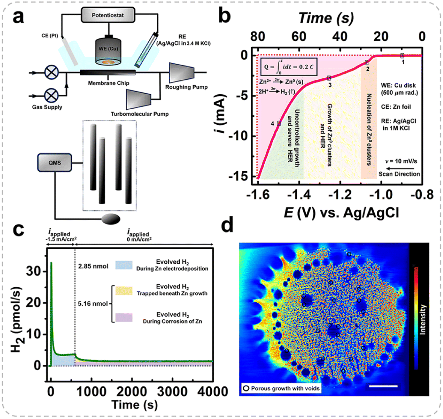 | ||
| Fig. 7 (a) ECMS setup schematic, with WE, RE, and CE representing the working, reference, and counter electrodes, respectively, and QMS denoting a quadrupole mass spectrometer. (b) Linear sweep voltammogram for Zn deposition on a Cu electrode in 0.5 M ZnSO4. (c) Hydrogen evolution vs. time at a current density of 1.5 mA cm−2, during current application (0–600 s) and after it stops (600–4000 s). (d) X-ray tomography image of Zn deposited at −1.5 mA cm−2 for 10 min, showing void-containing deposits (scale bar: 3 mm). The color bar indicates Zn intensity, with red signifying the highest and blue the lowest concentration. Reproduced from ref. 43 with permission from Wiley, copyright 2024. | ||
Fig. 7c presents mass spectrometry data for Zn electrodeposition on a copper substrate at a current density of 1.5 mA cm−2 for 600 s, followed by 3400 s of relaxation. During the deposition phase, only 0.3% of the total charge was associated with the HER, while the remaining charge was attributed to Zn deposition. The amount of hydrogen released was 2.84 nmol (the green region in Fig. 7c). Interestingly, hydrogen production continued for thousands of seconds even after the current ceased. Initially, hydrogen is likely derived from diffusion within the electrolyte and the release of microscopic bubbles trapped in the dendritic Zn matrix. Over time, the nearly constant hydrogen flux is attributed to Zn dissolution into Zn ions, accompanied by the HER via a corrosion process thermodynamically favored at the given potential and pH. These processes are distinctly highlighted in the colored regions of Fig. 7c. Assuming that the electrons required for the HER are entirely supplied by Zn corrosion, the corrosion rate was calculated to be 96 pg s−1, a negligible loss compared to the 61 μg of Zn deposited. Although this fraction appears minor, it significantly affects the long-term cycling performance of the Zn electrode, as shown in Fig. 7d. X-ray tomography reveals voids containing Zn clusters formed due to HER-induced bubble evolution. The hydrogen bubbles adsorbed on the Zn substrate obstruct Zn-ion flux to the electrode surface, leaving isolated regions without Zn deposition.
Recently, Wang et al. revisited hydrogen generation during Zn plating and stripping using operando gas chromatography (GC) in Zn//Zn symmetric cells with common mildly acidic electrolytes (e.g., 1 M ZnSO4 and Zn(OTf)2).44 An H-type cell with a Nafion 117 membrane was used to decouple the plating and the stripping processes and prevent gas crossover. Surprisingly, in addition to significant H2 evolution during plating, substantial H2 release was also observed during stripping, which is related to the oxidative dissolution of Zn metal exposing fresh Zn surfaces. This phenomenon was confirmed to result from enhanced chemical corrosion between Zn and interfacial water, rather than the electrochemical HER. Furthermore, hydrogen evolution was found to increase with current density during stripping, and Raman spectroscopy confirmed the presence of water decomposition byproducts, namely Zn(OH)2 and ZnO, on the Zn surfaces after plating and stripping. This is due to the local accumulation of OH− at the anode surface induced by the HER, which depletes H+ ions in the vicinity. The elevated OH− concentration reacts with Zn ions and SO42− in the electrolyte, leading to the formation of poorly reversible byproducts. These byproducts, characterized by low ionic conductivity and unstable, loose structures, not only impede the efficient plating and stripping of Zn but also expose the Zn anode to direct contact with the electrolyte. As a result, the HER persists, continuously consuming both active Zn and electrolyte, significantly undermining coulombic efficiency. Meanwhile, it exacerbates surface heterogeneity and electrode polarization, fostering the growth of loose and porous Zn dendrites that ultimately lead to battery failure. Therefore, it is essential to address this critical HER-induced challenge, alongside mitigating passivation and dendrite growth as shown in Fig. 8. The evolution of hydrogen bubbles not only compromises battery performance but also undermines the inherent safety of aqueous batteries, transforming them from safe to unsafe.
 | ||
| Fig. 8 (a) Schematic diagram of hydrogen bubble evolution, dendrite growth, and passivation issues in Zn electrodes. Reproduced from ref. 24 with permission from Elsevier, copyright 2023. (b) Symmetric coin cell before/after standing. Reproduced from ref. 45 with permission from Elsevier, copyright 2020. (c) Symmetric pouch cell before/after cycling. Reproduced from ref. 46 with permission from American Chemical Society (ACS), copyright 2021. | ||
5. Benefits of hydrogen bubble evolution
From the above summary, it is clear that hydrogen bubble evolution hampers mass transfer, resulting in inhomogeneous Zn deposition and localized Zn passivation over time. However, researchers have also identified certain benefits of hydrogen bubble evolution. Powers et al. found that in highly alkaline electrolytes, the type II ZnO passivation film (a more coherent film of ZnO (type II) inside a precipitated coating of ZnO particles (type I film)) that forms on the Zn electrode surface can act as a catalyst for hydrogen evolution.47 When the electrode potential surpasses the Zn/ZnO equilibrium potential, hydrogen bubbles begin to form on the electrode surface. The formation and release of these hydrogen bubbles mechanically disrupt the passivation film, effectively reactivating the electrode. This process can be microscopically observed, with the formation and detachment of hydrogen bubbles (Fig. 9a) causing the rupture (Fig. 9b) and removal of the passivation film, thereby exposing the electrode surface to the electrolyte and restoring its electrochemical activity. This hydrogen evolution-driven passivation film removal plays a crucial role in electrode reactivation. The generation of hydrogen bubbles not only aids in removing the passivation film but also helps to prevent the formation of excessively thick oxide layers on the electrode surface, thereby preserving its high performance. | ||
| Fig. 9 (a) Hydrogen bubble emergence from the ZnO film. (b) Crack in the ZnO film due to hydrogen bubbles. Reproduced from ref. 47 with permission from IOP Science, copyright 1971. | ||
Meanwhile, Hwu et al. employed real-time X-ray microscopy to investigate the influence of hydrogen bubble formation on the morphology of ramified Zn electrodeposition in mildly acidic media, exploring its potential for controlling this process.48 In their study, at current densities near the limiting value (130 mA cm−2), only a few hydrogen bubbles appeared, while a stable, dense-branching structure (Fig. 10a, image 8) formed gradually over time. The formation of hydrogen bubbles had minimal impact on this growth, which was also observed during potentiostatic deposition at low potentials. This suggests that the dense-branching morphology is typical in the absence of significant bubble interference in mild acidic media. However, at higher current densities (200 mA cm−2), hydrogen bubble generation became more prominent, inducing a significant morphological shift. Sequential microradiographs (Fig. 10a) revealed that bubbles initially covered most of the electrode surface, restricting nucleation sites and directing growth. This led to the formation of fern-like dendrites with a central stem and evenly spaced side branches (images 1–4). These structures then expanded rapidly outward before lateral growth took over, resulting in a dense, top-heavy deposit (images 5–8). The potential transient curve (Fig. 10b) illustrates three distinct stages: an initial voltage rise during double-layer charging, a sharp drop as the deposit formed, and a gradual decline as bubble formation diminished. The ramified growth increased the cathodic surface area, lowering the potential, while bubble activity induced oscillations during the intermediate stage. As bubble generation subsided, the potential stabilized, resulting in smooth curves.
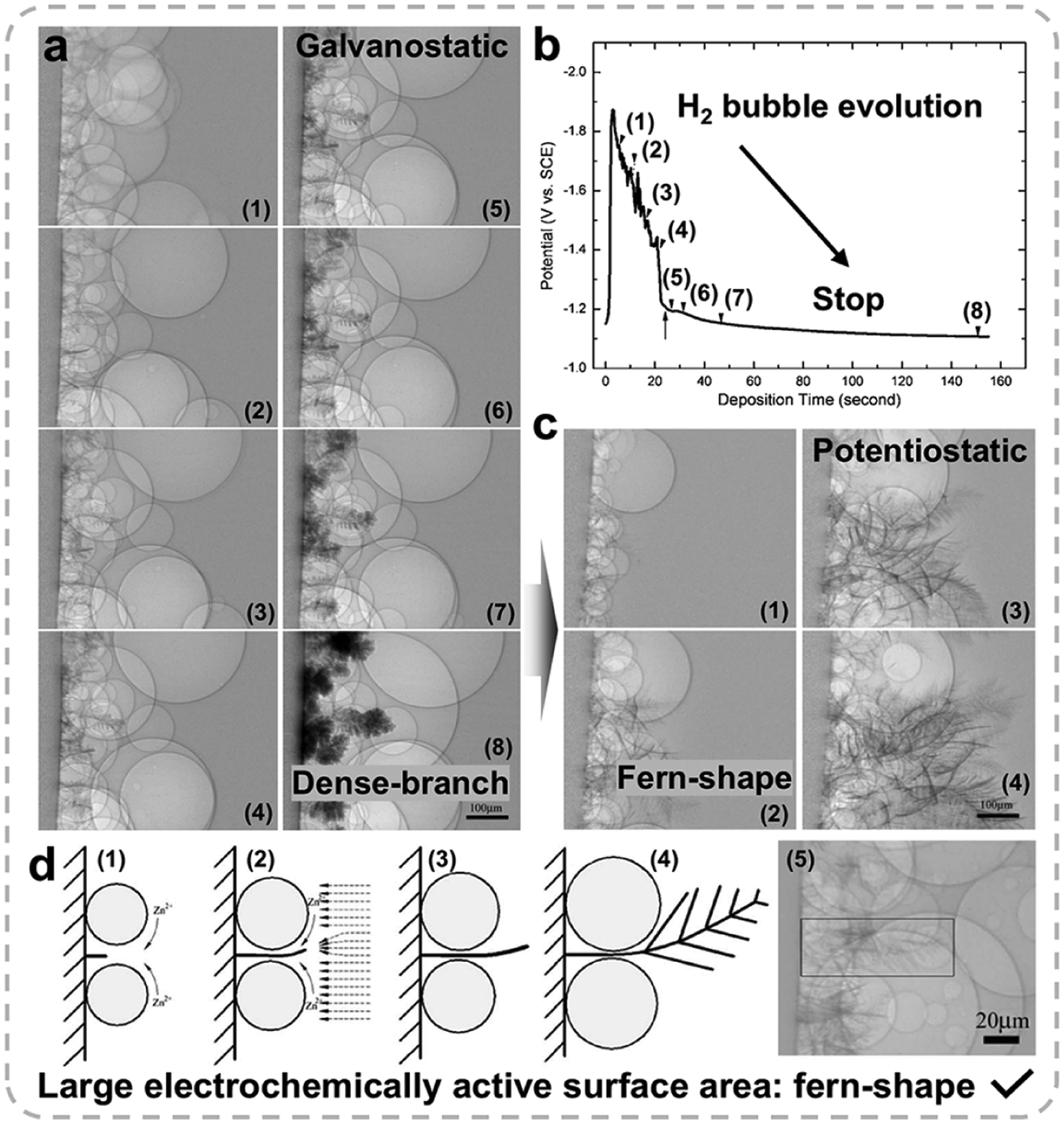 | ||
| Fig. 10 (a) Microradiographs of Zn deposition on a copper substrate (on the left) with galvanostatic plating at a current density of 200 mA cm−2. The images correspond to the times of (1) 5.4, (2) 10.6, (3) 15.8, (4) 21, (5) 26.2, (6) 31.4, (7) 47, and (8) 151 s. (b) Potential transient curve at a current density of 200 mA cm−2. The arrow labeled 1–8 corresponds to the microradiographs in (a). (c) Microradiographs of fern-shaped dendrite growth at −1.8 V at times of (1) 5.4, (2) 10.6, (3) 15.8, and (4) 21 s. (d) Schematic of fern-shaped dendrite formation with hydrogen bubbles and the electric field. Reproduced from ref. 48 with permission from IOP Science, copyright 2008. | ||
Fig. 10c illustrates Zn deposition at −1.8 V, where the effects of hydrogen bubble evolution predominate, leading to the formation of fern-shaped dendrites. In contrast to the galvanostatic mode, where dendrites transition to dense-branching structures (Fig. 10a), the potentiostatic mode preserves the fern-like morphology, a result of differences in bubble formation rates. These dendrites, with their extensive electrochemically active surface area, are well suited for Zn-air batteries.49Fig. 10d elucidates the mechanism behind fern-shaped dendrite formation. Hydrogen bubbles create two distinct regions: a Zn ion-depleted zone between the bubbles and a higher Zn ion concentration zone outside. This concentration gradient drives local convection (Fig. 10d, image 1), facilitating ion supply to the dendrite tip. While hydrogen bubbles inhibit lateral growth, the concentrated electric fields at the tip promote rapid vertical growth (images 2 and 3). As the main stem extends beyond the bubbles, side branches form, completing the fern-like structure (images 4 and 5). This study highlights how hydrogen bubbles and charging modes influence dendrite morphology, suggesting that controlled bubble-induced mass transfer could be utilized to engineer porous Zn electrodes tailored for specific applications.
Moreover, hydrogen bubbles that evolved during the process can serve as templates for fabricating porous Zn electrodes. Driven by buoyancy, these bubbles detach from the Zn surface once they reach a certain size, thus influencing the electrode structure. Han et al. introduced a dynamic bubble-template-assisted electrodeposition method to produce Zn with a foam-like architecture.50 This technique exploits the interaction between Zn deposition and hydrogen evolution, resulting in the formation of Zn foam around the bubbles. Scanning electron microscopy (SEM) images (Fig. 11a–h) demonstrate that varying Zn-ion concentrations (0.2, 0.1, 0.05, and 0.01 M) lead to porous Zn with progressively smaller pore sizes: approximately 300, 130, 40, and 12 μm, respectively. This observation underscores the influence of Zn-ion concentration on pore characteristics. When applied in alkaline Zn-air batteries, the Zn foam exhibits significant performance enhancements, as shown in Fig. 11i. In the initial cycle, the discharge voltage for the Zn foam reaches 1.33 V, compared to 1.26 V for pure Zn, while the charge voltage is 1.96 V for the foam versus 2.28 V for pure Zn. The narrower charge–discharge gap of the Zn foam (0.63 V) compared to Zn foil (1.02 V) emphasizes its superior efficiency. The interconnected porous structure facilitates efficient mass transport and accelerates reaction kinetics, leading to a substantial improvement in the electrochemical performance.
 | ||
| Fig. 11 Electrodeposited 3D porous Zn structures at various Zn ion concentrations: (a and b) 0.2 M, (c and d) 0.1 M, (e and f) 0.05 M, and (g and h) 0.01 M. NaBr and C2H3O2NH4 concentrations were 3 M and 1 M, respectively. (i) Zn–air battery cycling performance tests with a Zn electrode deposited with 0.01 M Zn ions and pure Zn foil: discharge–charge tests at a current density of 5 mA cm−2. Reproduced from ref. 50 with permission from Frontiers, copyright 2019. | ||
Despite the demonstrated benefits, further investigation is essential to achieve a deeper understanding of this complex subject, which integrates electrochemistry, electrocatalysis, two-phase fluid dynamics, and mass transport. In addition to employing the in situ optical and microscopic observation platforms described above, a range of advanced in situ characterization techniques at the atomic scale has been developed in recent years, including in situ Raman characterization, in situ photoluminescence, in situ liquid-phase transmission electron microscopy, and in situ electrochemical scanning tunneling microscopy, which can also be applied in subsequent research.51,52 Using in situ characterization techniques to trace the evolution of intermediates during the hydrogen evolution reaction is key to understanding mass transfer at the atomic and molecular levels. This allows for the study of various atomic interactions, revealing the impact of different sites and thus unveiling the underlying mechanisms of the HER. Regarding mitigating strategies, approaches should focus on electrode design (e.g., additives such as carbon-based materials, epitaxial deposition, crystal orientation design, and alloying techniques), interface engineering (e.g., artificial coatings and in situ SEI), and electrolyte optimization (e.g., zinc salts, electrolyte additives, hydrogels, organic electrolytes, ionic electrolytes, and solid-state electrolyte design) to minimize the detrimental effects of hydrogen evolution on zinc deposition and improve the overall performance of the system.53
6. Summary and perspectives
The evolution of hydrogen bubbles on Zn electrodes has proven to be a double-edged sword in the development of high-performance Zn-based batteries. On the one hand, the hydrogen evolution reaction (HER) contributes to the deterioration of mass transfer, leading to inhomogeneous Zn deposition, local passivation, and dendrite formation, ultimately compromising the efficiency and safety of the system. The generation of hydrogen bubbles exacerbates surface heterogeneity, accelerates electrode polarization, and promotes the growth of porous, unstable Zn dendrites, which are key factors in battery failure. Therefore, controlling the HER and mitigating its adverse effects are critical for the long-term stability and efficiency of Zn-based energy storage devices. On the other hand, hydrogen bubble evolution offers unique advantages that can be harnessed for electrode design. The buoyancy of hydrogen bubbles can facilitate the removal of passivation films on the Zn surface, effectively reactivating the electrode and maintaining its high electrochemical activity. Moreover, hydrogen bubbles have been shown to play a constructive role in shaping porous Zn structures, through gas-template-assisted electrodeposition. Recent advancements have highlighted the importance of understanding the interplay between hydrogen evolution and Zn deposition processes, as well as their influence on electrode morphology. By controlling bubble-induced convection, deposition modes, and electrolyte conditions, it is possible to engineer desired Zn electrodes tailored for specific applications.Future research should prioritize the development of innovative strategies to mitigate the detrimental effects of hydrogen evolution, while simultaneously exploiting its potential benefits. Key efforts should be directed towards refining methods to suppress the unwanted HER and to control hydrogen bubble formation and release with greater precision. These advances could enhance the efficiency, safety, and long-term stability of Zn-based batteries. Approaches such as electrolyte optimization, electrode surface engineering, and alloying techniques should be thoroughly explored to minimize the adverse impact of the HER on Zn deposition and enhance the overall performance of the system. At the same time, the beneficial effects of hydrogen bubbles, such as their role in enhancing local mass transfer and serving as templates for structured electrode formation, should be harnessed. Leveraging bubble-induced convection to facilitate controlled and rapid ion transfer could hold the key to optimizing the kinetics of some specific sluggish reactions. Furthermore, future research could benefit from integrating advanced characterization techniques, such as high-resolution real-time microscopy, to gain deeper insights into hydrogen bubble nucleation sites and their influence on electrode morphology. Such studies will provide crucial guidance for future regulation of bubble dynamics, enabling more effective control of the electrochemical environment. In parallel, exploring the interplay between hydrogen evolution and other electrochemical processes could open new pathways for the development of next-generation Zn-based energy storage systems that are not only more efficient but also safer and more durable.
Data availability
No primary research results, software or code have been included and no new data were generated or analysed as part of this work.Conflicts of interest
There are no conflicts to declare.Acknowledgements
W. Shang thanks the funding support from the Anhui Provincial Natural Science Foundation (2408085QE177) and P. Tan acknowledges the financial support from the National Innovative Talents Program (GG2090007001).References
- M. Zhang, J. Xiao, W. Tang, Y. He, P. Tan, M. Haranczyk and D. Y. Wang, Adv. Energy Mater., 2024, 14, 2401241 CrossRef CAS.
- Q. Ma, Y. Zheng, D. Luo, T. Or, Y. Liu, L. Yang, H. Dou, J. Liang, Y. Nie, X. Wang, A. Yu and Z. Chen, Adv. Mater., 2022, 34, 2108079 CrossRef CAS PubMed.
- M. Zhang, M. B. Gomes, A. Yusuf, G.-Z. Yin, C.-C. Sun and D.-Y. Wang, Eur. Polym. J., 2024, 215, 113246 CrossRef CAS.
- M. Zhang, A. Yusuf and D.-Y. Wang, J. Power Sources, 2024, 591, 233812 CrossRef CAS.
- Y. He, Z. Zhao, Y. Cui, W. Shang, Y. Chen and P. Tan, Energy Storage Mater., 2023, 57, 360–370 CrossRef.
- Q. Ma, R. Gao, Y. Liu, H. Dou, Y. Zheng, T. Or, L. Yang, Q. Li, Q. Cu, R. Feng, Z. Zhang, Y. Nie, B. Ren, D. Luo, X. Wang, A. Yu and Z. Chen, Adv. Mater., 2022, 34, 2207344 CrossRef CAS PubMed.
- Y. He, Y. Cui, W. Shang, Z. Zhao and P. Tan, Chem. Eng. J., 2022, 448, 137782 CrossRef CAS.
- Y. He, W. Shang, M. Ni, Y. Huang, H. Zhao and P. Tan, Chem. Eng. J., 2022, 427, 130862 CrossRef CAS.
- W. Shang, W. Yu, Y. Liu, R. Li, Y. Dai, C. Cheng, P. Tan and M. Ni, Energy Storage Mater., 2020, 31, 44–57 CrossRef.
- Y. Chen, X. Li, J. Lian, K. Fu, Z. Zhao, Y. He and P. Tan, ACS Appl. Mater. Interfaces, 2024, 16, 42321–42331 CrossRef CAS PubMed.
- Y. Cui, Y. He, W. Yu, Y. Ma, Z. Zhao, J. Yu and P. Tan, J. Power Sources, 2024, 601, 234294 CrossRef CAS.
- Y. Cui, Y. He, W. Yu, W. Shang, J. Yu and P. Tan, ACS Appl. Mater. Interfaces, 2023, 15, 3028–3036 CrossRef CAS PubMed.
- Y. He, Y. Cui, Y. Chen and P. Tan, Innovation Energy, 2024, 1, 100028 CrossRef.
- T. P. Zhou, N. Zhang, C. Z. Wu and Y. Xie, Energy Environ. Sci., 2020, 13, 1132–1153 RSC.
- J. W. Zhou, J. L. Cheng, B. Wang, H. S. Peng and J. Lu, Energy Environ. Sci., 2020, 13, 1933–1970 RSC.
- Y. He, W. Shang and P. Tan, Carbon Neutralization, 2024, 3, 773–780 CrossRef.
- W. Shang, H. Wang, W. Yu, Y. He, Y. Ma, R. Li, Z. Wu and P. Tan, Cell Rep. Phys. Sci., 2022, 3, 100904 CrossRef CAS.
- Z. Zhao, W. Yu, W. Shang, Y. He, Y. Ma, Z. Zhang and P. Tan, Int. J. Energy Res., 2022, 46, 7694–7703 CrossRef CAS.
- Z. Zhao, W. Yu, W. Shang, Y. He, Y. Ma, Z. Zhang and P. Tan, J. Power Sources, 2022, 543, 231844 CrossRef CAS.
- J. Yi, P. C. Liang, X. Y. Liu, K. Wu, Y. Y. Liu, Y. G. Wang, Y. Y. Xia and J. J. Zhang, Energy Environ. Sci., 2018, 11, 3075–3095 RSC.
- W. Yu, W. Shang, P. Tan, B. Chen, Z. Wu, H. Xu, Z. Shao, M. Liu and M. Ni, J. Mater. Chem. A, 2019, 7, 26744–26768 RSC.
- Y. He and P. Tan, Chem. – Eur. J., 2024, 30, e202303477 CrossRef CAS PubMed.
- Z. Zhao, Y. He, W. Yu, W. Shang, Y. Ma and P. Tan, Proc. Natl. Acad. Sci. U. S. A., 2023, 44, e2307847120 CrossRef PubMed.
- J. Chen, W. Zhao, J. Jiang, X. Zhao, S. Zheng, Z. Pan and X. Yang, Energy Storage Mater., 2023, 59, 102767 CrossRef.
- D. Qiu, B. Li, C. Zhao, J. Dang, G. Chen, H. Qiu and H. Miao, Energy Storage Mater., 2023, 61, 102903 CrossRef.
- W. Xie, K. Zhu, H. Yang and W. Yang, Adv. Mater., 2024, 36, e2306154 CrossRef PubMed.
- Y. He, Y. Cui, Z. Zhao, Y. Chen, W. Shang and P. Tan, Energy Rev., 2023, 2, 100015 CrossRef.
- G. M. Whitney and C. W. Tobias, AIChE J., 1988, 34, 1981–1995 CrossRef CAS.
- J. Yu, W. Yu, Z. Zhang and P. Tan, Chem. Eng. J., 2024, 481, 148556 CrossRef CAS.
- J. Yu, Z. Zhao, Z. Zhang, K. Sun and P. Tan, Energy Storage Mater., 2024, 73, 103823 CrossRef.
- O. Dubrovski and O. Manor, Phys. Rev. Mater., 2021, 5, 123402 CrossRef CAS.
- G. Li, Adv. Energy Mater., 2021, 11, 2002891 CrossRef CAS.
- P. Tan, W. Kong, Z. Shao, M. Liu and M. Ni, Prog. Energy Combust. Sci., 2017, 62, 155–189 CrossRef.
- Y. Cui, Y. He, W. Yu, W. Shang, Y. Ma and P. Tan, Electrochim. Acta, 2022, 418, 140344 CrossRef CAS.
- Y. He, Y. Cui, W. Shang, Z. Zhao and P. Tan, Chem. Eng. J., 2022, 438, 135541 CrossRef CAS.
- W. Yu, W. Shang, Y. He, Z. Zhao, Y. Ma and P. Tan, Chem. Eng. J., 2022, 431, 134032 CrossRef CAS.
- C. Yang, X. Liu, K. Yang, Y. Lai, K. Zhang and Z. Tian, J. Solid State Electrochem., 2020, 25, 611–616 CrossRef.
- K. W. Choi, D. Hamby, D. N. Bennion and J. Newman, J. Electrochem. Soc., 1976, 123, 1628 CrossRef CAS.
- K. W. Choi, D. N. Bennion and J. Newman, J. Electrochem. Soc., 1976, 123, 1616 CrossRef CAS.
- J. St-Pierre and D. L. Piron, J. Electrochem. Soc., 1992, 139, 105 CrossRef CAS.
- A. Shah and J. Jorne, J. Electrochem. Soc., 1989, 136, 153 CrossRef CAS.
- J. Dundálek, I. Šnajdr, O. Libánský, J. Vrána, J. Pocedič, P. Mazúr and J. Kosek, J. Power Sources, 2017, 372, 221–226 CrossRef.
- K. Roy, A. Rana, J. N. Heil, B. M. Tackett and J. E. Dick, Angew. Chem., Int. Ed., 2024, 63, e202319010 CrossRef CAS PubMed.
- B. Liu, Z. Xu, C. Wei, Z. Zhu, Y. Fang, X. Lei, Y. Zhou, C. Tang, S. Ni, H. Pan and G. Wang, eScience, 2024, 100330 CrossRef.
- Z. Cai, Y. Ou, J. Wang, R. Xiao, L. Fu, Z. Yuan, R. Zhan and Y. Sun, Energy Storage Mater., 2020, 27, 205–211 CrossRef.
- Z. Cai, Y. Ou, B. Zhang, J. Wang, L. Fu, M. Wan, G. Li, W. Wang, L. Wang, J. Jiang, Z. W. Seh, E. Hu, X.-Q. Yang, Y. Cui and Y. Sun, J. Am. Chem. Soc., 2021, 143, 3143–3152 CrossRef CAS PubMed.
- R. W. Powers, J. Electrochem. Soc., 1971, 118, 685 CrossRef CAS.
- P.-C. Hsu, S.-K. Seol, T.-N. Lo, C.-J. Liu, C.-L. Wang, C.-S. Lin, Y. Hwu, C. H. Chen, L.-W. Chang, J. H. Je and G. Margaritondo, J. Electrochem. Soc., 2008, 155, D400 CrossRef CAS.
- C. M. López and K.-S. Choi, Langmuir, 2006, 22, 10625–10629 CrossRef PubMed.
- P. Liu, X. Ling, C. Zhong, Y. Deng, X. Han and W. Hu, Front. Chem., 2019, 7, 656 CrossRef CAS PubMed.
- Y.-H. Wang, X. Jin, M. Xue, M.-F. Cao, F. Xu, G.-X. Lin, J.-B. Le, W.-M. Yang, Z.-L. Yang, Y. Cao, Y. Zhou, W. Cai, Z. Zhang, J. Cheng, W. Guo and J.-F. Li, Joule, 2023, 7, 1652–1662 CrossRef CAS.
- Y.-H. Wang, S. Zheng, W.-M. Yang, R.-Y. Zhou, Q.-F. He, P. Radjenovic, J.-C. Dong, S. Li, J. Zheng, Z.-L. Yang, G. Attard, F. Pan, Z.-Q. Tian and J.-F. Li, Nature, 2021, 600, 81–85 CrossRef CAS PubMed.
- A. Bayaguud, Y. Fu and C. Zhu, J. Energy Chem., 2022, 64, 246–262 CrossRef CAS.
| This journal is © The Royal Society of Chemistry 2025 |