
 Open Access Article
 This Open Access Article is licensed under a Creative Commons Attribution-Non Commercial 3.0 Unported Licence
Design and development of a low-cost imidazole-based hole transporting material for perovskite solar cells†
Fatemeh
Sadeghi
a,
Babak
Pashaei
b,
Babak Nemati
Bideh
 c,
Negin
Sabahi
a,
Hashem
Shahroosvand
*a and
Mohammad Khaja
Nazeeruddin
*d
c,
Negin
Sabahi
a,
Hashem
Shahroosvand
*a and
Mohammad Khaja
Nazeeruddin
*d
aGroup for Molecular Engineering of Advanced Functional Materials, Department of Chemistry, University of Zanjan, Zanjan, Iran. E-mail: shahroos@znu.ac.ir
bDepartment of Inorganic Chemistry, Faculty of Chemistry, University of Mazandaran, Babolsar, Iran
cInorganic Chemistry Department, Faculty of Chemistry, Bu-Ali Sina University, Hamedan, Iran
dGroup for Molecular Engineering of Functional Materials, Institute of Chemical Sciences and Engineering, Ecole polytechnique fédérale de Lausanne, Sion CH-1951, Switzerland. E-mail: mdkhaja.nazeeruddin@epfl.ch
First published on 5th September 2023
Abstract
Low-cost and facile synthesis routes of hole-transporting materials (HTMs) are promising approaches to minimize the total cost of perovskite solar cells (PSCs) on both laboratory and commercial scales. Herein, we report 2-(3-nitrophenyl)-4,5-diphenyl-1H-imidazole (1) as a cost-effective HTM for PSCs. HTM 1 was synthesized without using any catalyst and purification process from largely available commercial precursors. HTM 1 is soluble in many organic solvents and it can be formed as a fine thin layer on top of a perovskite using a spin-coating process. In particular, density functional theory (DFT) studies showed that the energy levels of its frontier molecular orbitals are well aligned with the energy levels of the perovskite layer. Using HTM 1 in PSCs, a power conversion efficiency (PCE) of 15.20% was achieved, which was comparable to 2,2′,7,7′-tetrakis-(N, N-di-p-methoxyphenylamine)-9,9′-spirobifluorene (spiro-OMeTAD, HTM 2)'s PCE of 18.21%. In this study, we revealed that HTM 1 based on simple imidazole can be explored as an alternative to spiro-OMeTAD, HTM 2, providing a way for synthesizing simple and efficient HTMs for low-cost PSCs.
1. Introduction
Organic–inorganic perovskite solar cells (PSCs) have attracted much attention owing to their high power conversion efficiencies (PCEs) reaching over 25% due to their excellent optoelectronic properties.1,2 Although PCE of PSCs has skyrocketed, several device issues still need to be resolved, especially long-term stability. A PSC comprises a hole-transporting layer (HTL), an organic–inorganic lead halide perovskite, and an electron-transporting layer (ETL), sandwiched between two electrodes. Generally, a higher PSC performance can be achieved using a light harvester or a perovskite active layer, because of its properties such as intense light absorption,3 considerable charge carrier diffusion length4 with the capability to transport charge effectively,5 and low charge recombination rates.3A HTM is one of the quintessential components required for achieving efficient and stable PSC devices,6 which can be attributed to the following reasons:7 (i) HTM extracts holes from perovskite and transports to the contact, and suppresses charge recombination at the interface,8 (ii) prevents the contact of the light absorber with the cathode (Au and Ag), and (iii) blocks the penetration of moisture and water.9 An efficient HTL in PSCs must have high thermal and chemical stability, high mobility, and good consistency with the energy levels of perovskites.10 To date, HTMs have been divided into organic11,12 and inorganic13 p-type semiconductors. Small molecule HTMs are great candidates for PSCs, due to their well-known structures, good reproducibility, and adjustable electron energy levels.14 Among the available small organic HTMs, triarylamine-containing compounds spiro-OMeTAD (HTM 2) and polytriarylamine (PTAA) are the best and the most effective small molecule-based HTMs used in PSCs.15 In PSCs, HTM 2 is the most well-known used organic HTM, which facilitates achieving a high PCE of PSCs. However, small HTMs suffer from their complicated and expensive synthesis approaches which need multi-step preparation and purification procedures.16,17 For instance, the commercial price of HTM 2 reaches 170–425 $ g−1.18 Therefore, one of the hottest research topics in the field of PSCs is the exploration of an efficient and low-cost HTM.
In recent years, small molecule-based HTMs with donor–acceptor (D–A) structures have been extensively studied owing to high dipole moment and intramolecular charge-transfer (ICT) features.19,20 An electron-withdrawing moiety stabilizes the highest occupied molecular orbital (HOMO) energy level, resulting in improved open-circuit voltage (VOC) and reduced charge recombination.21 Imidazole derivatives act effectively as electron donor moieties, formation the hydrogen bonding and so on22,23 due to the high twisting nature of the diphenyl-imidazole unit. These materials are extensively used in the preparation of a large number of optoelectronic devices, light emitting electrochemical cells (LECs) and organic light-emitting diodes (OLEDs).24–26 In this study, a HTM based on imidazole (1) was synthesized and characterized, by incorporating imidazole core and phenyl units, as well as its application potential in PSCs was investigated. Using HTM 1 in PSCs we obtained a VOC of 1.05 V, a short-circuit current density (JSC) of 19.05 mA cm−2 and a fill factor (FF) of 0.76. The obtained results are comparable with those of HTM 2 under the same conditions.
2. Experimental
2.1. Materials
All starting materials for synthesizing HTM 1 were purchased from commercial sources (Sigma–Aldrich and Merck Co.) and used without additional purification. HTM 1 was synthesized by using the previously reported methods.27 Spiro-OMeTAD, which was named HTM 2 was obtained from Sigma Aldrich.2.2. Synthesis of 2-(3-nitrophenyl)-4,5-diphenyl-1H-imidazole (1)
For the synthesis of HTM 1, benzyl (0.21 g, 0.1 mmol), 3-nitrobenzaldehyde (0.151 g, 0.1 mmol), and ammonium acetate (1 g) in the presence of glacial acetic acid (10 ml) were refluxed under a nitrogen atmosphere for 15 h at 127 °C. After reaching ambient temperature, cold water was poured into the reaction mixture and neutralized with ammonium hydroxide solution to obtain a precipitate. Then water and acetic acid were used to wash the precipitate. For further purification, crystallization was performed using ethanol as the solvent (yellow precipitate, 60%). 1H NMR (250 MHz, CDCl3, δ ppm): 7.29–7.34 (m, 6H), 7.49–7.52 (d, 4H), 7.70 (t, 1H), 8.16 (d, 1H), 8.45 (d, 1H), 8.91 (s, 1H). 13C NMR (250 MHz, CDCl3, δ ppm): 120.5, 123.5, 126.8, 127.25, 128.10, 128.49, 128.65, 128.80, 129.1, 131.3, 131.40, 132.75, 132.82, 135.45, 137.90, 142.57, 146.7. FT-IR (KBr, cm−1): 3292 (w) (N–H), 3069 (m), 2967 (m) (C–H), 1705 (m), 1652 (m), 1616 (w), 1540 (s) (C![[double bond, length as m-dash]](https://www.rsc.org/images/entities/char_e001.gif) C), 1522 (s), 1480 (m), 1349 (s), 1203 (w), 1089 (m), 1071 (m), 970 (w), 907 (m), 767 (s), 669 (s), 510 (m). CHN for C21H15N3O2 (%); anal. calcd: C, 73.89; H, 4.43; N, 12.31; O, 9.37. Found: C, 73.82; H, 4.46; N, 12.27. ESI-MS: m/z calcd. for C21H15N3O2 341.12; found 340.21.
C), 1522 (s), 1480 (m), 1349 (s), 1203 (w), 1089 (m), 1071 (m), 970 (w), 907 (m), 767 (s), 669 (s), 510 (m). CHN for C21H15N3O2 (%); anal. calcd: C, 73.89; H, 4.43; N, 12.31; O, 9.37. Found: C, 73.82; H, 4.46; N, 12.27. ESI-MS: m/z calcd. for C21H15N3O2 341.12; found 340.21.
2.3. Solar cell fabrication
To prepare the devices, fluorine-doped tin oxide (FTO)-coated glass substrates were used. After etching portion of FTO-coated glass substrates with HCl solution in ethanol and Zn powder, they were washed with a detergent, distilled water, acetone, ethanol, and iso-propanol, respectively. Then, a compact TiO2 blocking layer was deposited by spin-coating at 2000 rpm for 30 s and heated at 500 °C for 30 min. The solution of this layer was prepared from Ti-iso-propoxide and HCl in dry ethanol. The mesoporous TiO2 layer (diluted TiO2 in ethanol) was deposited using the same technique at 2000 rpm for 10 s and was reheated at 500 °C for 30 min. The mixed perovskite precursor solution was prepared by dissolving PbI2 (1.15 M), formamidinium iodide (FAI) (1.10 M), PbBr2 (0.2 M), and methylammonium bromide (MABr) (0.2 M) in an anhydrous solvent dimethylformamide (DMF):dimethyl sulfoxide (DMSO) with a volume ratio of 4![[thin space (1/6-em)]](https://www.rsc.org/images/entities/char_2009.gif) :1 and then films were annealed at 100 °C for 90 min. The perovskite solution was spin-coated in a two-step procedure at 1000 and 6000 rpm for 10 and 30 s, respectively. Next, HTM (HTM 1:20.1 mg mL−1 or HTM 2:72.3 mg mL−1) dissolved in chlorobenzene was spin-coated at 4000 rpm for 20 s, with the addition of lithium bis(trifluoro methane sulfonyl) imide (LiTFSI) (520 mg mL−1 in acetonitrile) and tert-butyl pyridine (28.8 μL). The HTMs dissolved in chlorobenzene were spin-coated at 4000 rpm for 20 s, with the addition of lithium bis(trifluoro methane sulfonyl)imide (LiTFSI) and tert-butyl pyridine. Finally, the gold cathode was deposited under a high vacuum by thermal evaporation.
:1 and then films were annealed at 100 °C for 90 min. The perovskite solution was spin-coated in a two-step procedure at 1000 and 6000 rpm for 10 and 30 s, respectively. Next, HTM (HTM 1:20.1 mg mL−1 or HTM 2:72.3 mg mL−1) dissolved in chlorobenzene was spin-coated at 4000 rpm for 20 s, with the addition of lithium bis(trifluoro methane sulfonyl) imide (LiTFSI) (520 mg mL−1 in acetonitrile) and tert-butyl pyridine (28.8 μL). The HTMs dissolved in chlorobenzene were spin-coated at 4000 rpm for 20 s, with the addition of lithium bis(trifluoro methane sulfonyl)imide (LiTFSI) and tert-butyl pyridine. Finally, the gold cathode was deposited under a high vacuum by thermal evaporation.
2.4. Characterization
A solar simulator (Newport, Oriel Class A, 91195A) with Keithley2400 Digital Source Meter was used to measure current density–voltage (J–V) characteristics. The spectra of 1H NMR and 13C NMR were recorded on a Bruker 250 MHz spectrometer with CDCl3 and tetramethyl silane (TMS) was used as an internal standard. Elemental analyses were performed by using a Vario EL CHN analyzer. A PerkinElmer 597 spectrometer was used for obtaining FT-IR spectra. Ultraviolet-visible (UV-Vis) and photoluminescence (PL) spectra were obtained using an Ultrospec 3100 pro and an AvaSpec-125 spectrophotometer, respectively, in chloroform solvent. A SAMA500 potentiostat electrochemical analyzer with a conventional three-electrode cell was used for electrochemical studies in CHCl3 solvent and 0.10 M tetrabutylammonium perchlorate as the supporting electrolyte. A Pt wire, Ag/AgCl, and a Pt disk were used as a counter electrode, reference electrode, and working electrode, respectively.The HOMO/LUMO energy levels were calculated using CV data by the following equation: EHOMO = –(Eox(vs. Fc/FC+)+ 4.8 eV) (Eox and Ered are oxidation and reduction potentials, which are directly obtained from first half-waves). The reduction potential of ferrocene was found to be 0.43, ELUMO = EHOMO + E0–0 eV, and E0–0 was calculated from the intersection of absorption and emission spectra in acetonitrile solution. Egap = –EHOMO – ELUMO was obtained from the UV-Vis and PL spectra.25,28–30
The scanning electron microscopy (SEM) images were obtained using a MIRA III model (TESCAN Co.). The space-charge limited current (SCLC) method was applied to investigate the hole mobilities of the HTMs.31 The molecular and electronic structures were studied using density functional theory (DFT) calculations on a Gaussian 09 package at the B3LYP/6-31G* level. The Gauss View 5.0.8 was used to visualize molecular orbitals.
3. Results and discussion
The synthesis method and molecular structure of 1 are shown in Fig. 1 and explained in the experimental section in detail. To characterize HTM 1, various techniques such as electrochemical, thermoanalytical, and spectroscopic were used and compared with the results of 2 as the HTM benchmark. For example, the absence of a singlet peak in the 1HNMR spectrum of 1 (please see Fig. S1 in ESI†) is related to N–H of imidazole and methyl groups, confirming the successful synthesis of 1. The 1HNMR spectrum of compound 1 consists of two parts of the precursor along with the hydrogen of the imidazole ring moiety. Two regions of 8–9 and 7.5–8 ppm can be attributed to the phenyl ring of the imidazole part and the phenyl ring of the benzyl moieties. | ||
| Fig. 1 Synthesis route and molecular structures of HTM 1, D = donor, (A) = acceptor, and spiro-OMeTAD, named HTM 2. | ||
In particular, the hydrogen of the imidazole part confirms the formation of the skeleton of the 1 HTM, because when treated with D2O, the peak corresponding to the hydrogen at 5.5 ppm disappears due to the exchange to the deuterium.
In the FT-IR spectrum, disappearance of a strong signal of the benzyl group at 1682 cm−1 and appearance of the peak of N–H at 3292 cm−1 indicate the successful formation of an imidazole ring.
Fig. 2a displays UV-Vis absorption and PL emission spectra of the synthesized HTM 1 and 2 in CHCl3 solutions. The UV-Vis spectrum of 1 demonstrated main bands in regions of 281 and 316, due to n → π* and π → π* transitions. For comparison, we also investigated the absorption and PL spectra of 2 as a benchmark HTM. As seen in Fig. 2a, the absorption spectrum of 1 is blue-shifted in comparison with 2. Moreover, 1 has an emission band in the blue region at 486.6 nm at room temperature. The PL emission spectrum of 1 red-shifted around 65 nm relative to that of 2. Additionally, from the intersection point between the UV-Vis absorption and the PL spectra, the optical band gaps (Eo–o) of the HTMs were estimated and Eo–o was 2.80 eV for 1, smaller than that of 2 (2.95 eV). The electrochemical behaviors of the HTMs were investigated using cyclic voltammetry (CV) to determine their frontier molecular orbital energy levels. For compound 1 we observed two oxidation peaks, whereas three oxidation peaks were apparent in the CV curve of 2, in agreement with previous studies (Fig. 2b).32 The first half-wave oxidation potentials appeared at 0.42 and 0.6 V corresponding to 1 and 2, respectively. The oxidation potential of 1 is lower than that of 2 (Table 1). Using photoelectron yield spectroscopy, the energy levels of the HOMO (EHOMO) of 1 and 2 were found to be –4.82 and –5.0 eV, respectively. The lowest unoccupied molecular orbital (LUMO) energy levels (ELUMO) are –2.32 and –2.05 eV, for 1 and 2, respectively, obtained using equation ELUMO = EHOMO + Eo–o. These results indicate that the HOMO energy level of HTM 1 has good matching with the HOMO energy level of the perovskite layer (–5.43 eV), resulting in efficient hole transfer in the perovskite layer. Moreover, to determine the effect of additives such as LiTFSI and t-butyl pyridine, the ionization potentials of doped HTM (Ip*) are calculated and the data are given in Table 1 and Fig. 5a. It is useful to note that Ip* removes the electrons from the HOMO to generate holes, stabilizes the HOMO at about 0.3 eV, and subsequently enhances the efficiency via increasing Voc.
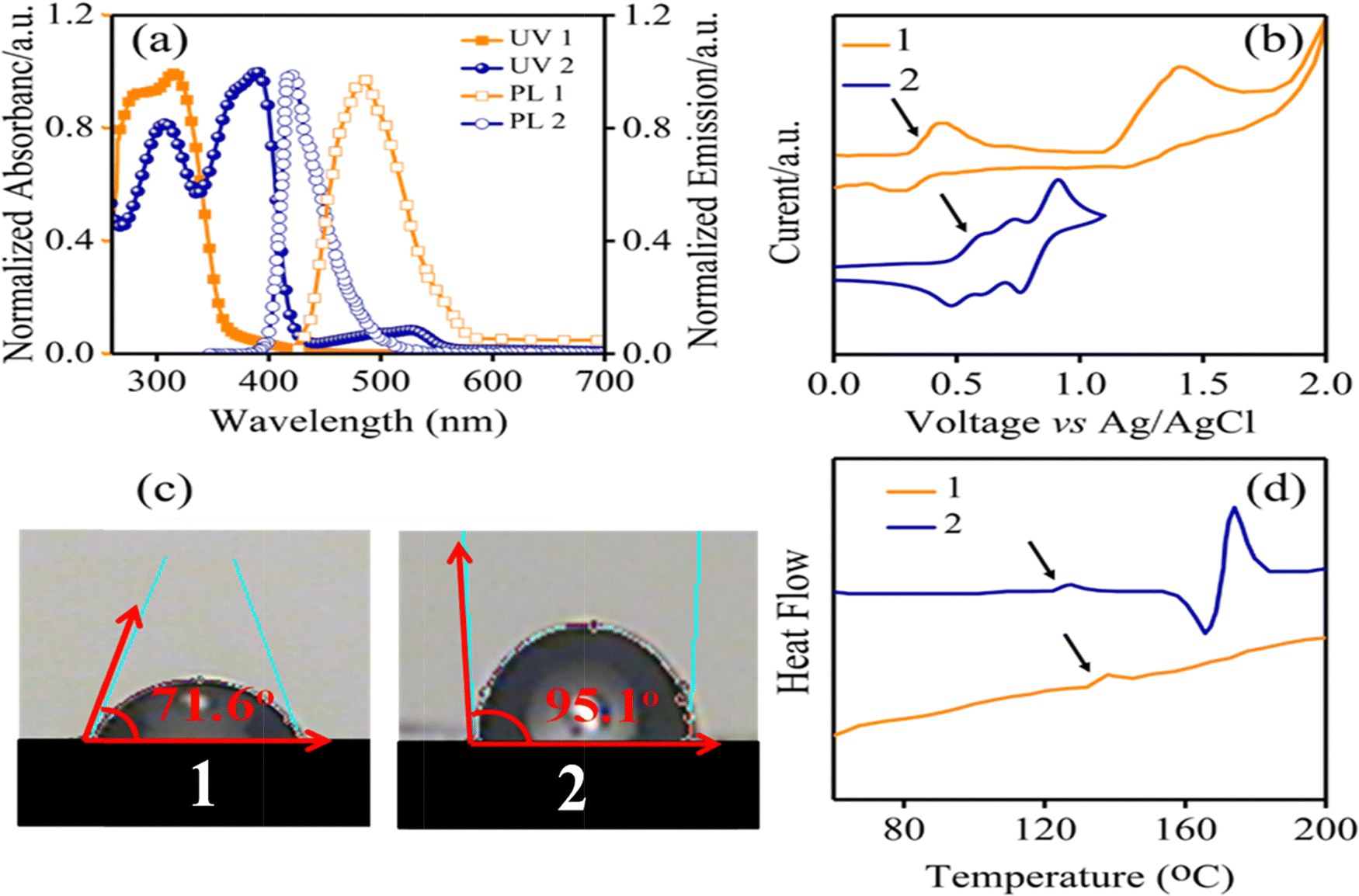 | ||
| Fig. 2 (a) UV-Vis and PL spectra, (b) CV curves, (c) contact angles and (d) DSC curves of HTMs 1 and 2. | ||
| HTM | λ abs [nm] | λ em [nm] | E o–o [eV] | E OX [V] | E HOMO [eV] | E LUMO [eV] | T g [°C] | η quench | Hole mobilityi [cm2 V−1 s−1] |
|---|---|---|---|---|---|---|---|---|---|
| a UV-Vis and photoluminescence spectra were measured in CHCl3 solution. b UV-Vis and photoluminescence spectra were measured in CHCl3 solution. c E o–o was estimated by the energy corresponding to the intersection of the UV-Vis absorption and PL spectra. d From CV measurements, E1/2 = 1/2(Epa + Epc); 0.1 M chloroform/tetrabutylammonium perchlorate (TBAP) versus Ag/AgCl at a scan rate of 80 mV s−1. e Measured by photoelectron yield spectroscopy with doping. f E LUMO = EHOMO + Eo–o. g Glass transition. h η quench = (PLbare − PLquench)/PLbare, where PLbare and PLquench are the integrated PL intensities of perovskite on sapphire substrates without and with the HTM layer, respectively. i Estimated using the SCLC method. | |||||||||
| 1 | 281, 316 | 486 | 2.80 | 0.42 | −4.82 | −2.32 | 139 | 0.94 | 1.50 × 10⁻⁵ |
| 2 | 304, 378 | 421 | 2.95 | 0.6 | −5.00 | −2.05 | 125 | 0.88 | 5.23 × 10⁻⁵ |
Furthermore, the hydrophobicity of HTMs is one of the important parameters to increase PSC stability through the blocking of diffusion of moisture and water penetration, which are paramount factors that decompose CH3NH3PbI3 to PbI2.33,34 Accordingly, the water contact angle measurements were carried out for HTM 1, and was estimated to be 71.6° (Fig. 2c). The obtained results show the good hydrophobicity behavior of HTM 1, which efficiently avoids the water penetration into the perovskite active layer, consequently restraining degradation effects.35 Fig. S2 in the ESI,† and Fig. 2d illustrate the thermogravimetric analysis (TGA) and differential scanning calorimetry (DSC) analysis results of 1 and 2 to explore their thermal stability. According to TGA experiments, a relatively high decomposition temperature (Td) can be observed for HTM 1. Surprisingly, a glass transition temperature (Tg) of about 139 °C was observed for HTM 1, which is higher than that of HTM 2 (125 °C),36 indicating a relatively high thermal stability behaviour of HTM 1. This result is critical because the essential limitation of small molecules, which frequently show low Tg points, consequently restricting their applications in PSCs, was addressed with the new HTM. Charge carrier transport properties of a HTM play a key role in indicating its ability to transport charge from the absorbent layer to the electrode.37 The SCLC method is applied to investigate the hole mobilities of the HTM (please see Fig. S3 in the ESI†) and the results are summarized in Table 1. The hole mobility of pristine HTM 1 is 1.50 × 10⁻⁵ cm2 V−1 s−1, which is close to that of HTM 2 (5.23 × 10⁻⁵ cm2 V−1 s−1).
The electronic properties of HTMs 1 and 2 were investigated using DFT calculations. Fig. 3 shows the energy levels of the calculated HOMO and LUMO of HTMs 1 and 2. The electron density of the HOMO is localized on the benzyl and imidazole cores, while the LUMO is delocalized over nitrobenzene. The HOMO energy levels of 1 and 2 are −4.95 eV and −4.33 eV, respectively, indicating the better matching of the HOMO energy levels of the perovskite layer and HTM 1. The energy difference between HOMO energy levels of perovskite and 1 HTM is −0.48 eV, which is lower than that of 2 with an energy gap of about −0.84 eV. This indicates more facile hole transport from the perovskite layer to 1 HTM.
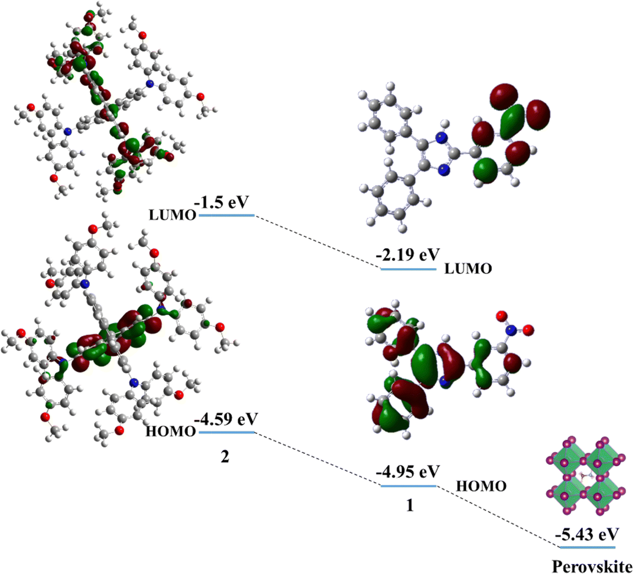 | ||
| Fig. 3 The molecular and electronic structures and the energy levels of the HOMO and LUMO of HTMs 1 and 2. | ||
In the following, the steady-state PL spectroscopy measurement was employed to study the ability of HTMs to extract the holes from the active layer. The process of the hole extraction hinders the recombination of radiative charge in the perovskite active layer,38 which consequently shows a PL quenching.39 The new HTM quenches the PL of the perovskite more effectively than HTM 2, as shown in Fig. 4.40 The PL quenching factor (ηquench) of HTM 1 is 0.94 and ∼6% higher than the one of HTM 2 (according to the equation: ηquench = (PLbare – PLquench)/PLbare, where PLbare is the integrated PL intensity in structure glass/perovskite, while PLquench is the integrated PL intensity in structure glass/perovskite/HTM, Table 1). The aforementioned discussion indicates that HTM 1 has all necessary parameters of a promising HTM for achieving an efficient PSC.
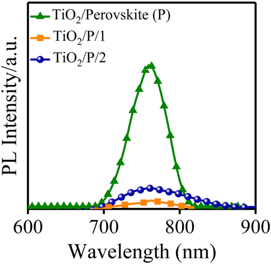 | ||
| Fig. 4 Steady-state PL spectra of the perovskite without and with HTMs 1 and 2. | ||
Fig. 5a shows the diagram of energy levels of 1 and 2, which confirm that the HOMO energy levels of 1 and perovskite have been optimally matched, indicating that 1 efficiently decreased the energy barrier to the hole extraction from the active layer.
 | ||
| Fig. 5 (a) Diagram of energy levels of TiO2/perovskite, HTM 1 and 2 (doped/white box, un-doped/blue box), (b) device structure corresponding to the compounds applied in the investigated PSCs and (c) SEM picture of the cross-section of a demonstrative PSC based on structure FTO/TiO2/perovskite/1/Au. | ||
Based on the outstanding spectrochemical and electrochemical results, the new HTM was used in PSCs as the HTM by adopting the following architecture:41 FTO/TiO2 (blocking layer)/TiO2 (mesoporous layer)/perovskite/HTM/Au (Fig. 5a and b). The cross-sectional SEM confirmed the configuration of the PSC fabricated with HTM 1 (Fig. 5c), including the TiO2 layer with a thickness of 350 nm and perovskite as a light-harvesting layer, and the HTM layer thicknesses were 450 and 450 nm. Moreover, cross-sectional elemental mapping images of a solar cell obtained through energy-dispersive X-ray (EDX) analysis are shown in Fig. S4 (please see the ESI†), indicating well-defined layers and good penetration of Pb and I inside the TiO2 layer.
Fig. 6a displays J–V curves obtained from 1- and 2-based PSCs and the results are also given in Table 2. Under standard conditions, the devices fabricated with HTMs 1 and 2 exhibited PCEs of 15.20% and 18.21%, respectively. The VOC based on HTM 1 is 1.05 V lower than that of HTM 2 (1.12 V). This is due to the HOMO energy difference of 1.42 Additionally, the 1-based device indicated a lower JSC in comparison to HTM 2 (Table 2). To explain the lowering of JSC of HTM 1 compared to a reference, it is useful to note that some factors play a key role in increasing JSC, such as π-extension of the molecular structure, the HOMO–LUMO consistency with other components, hole mobility and conductivity of the HTM and so on. However, as mentioned above about hole mobility and conductivity values, the HTM 1-based device exhibited a lower JSC in comparison to HTM 2 (Table 2), most likely attributed to the lower lying LUMO level leading to poor electron blocking and greater charge recombination occurring at the perovskite–HTM interfaces.43,44 The fill factor (FF) of PSCs based on 2 is considerably higher than that of the PSC fabricated with 1, which is attributed to the high conductivity of 2, thus reducing the overall resistance of the device.45 According to the J–V curves of the device, there is a small hysteresis between forward and reverse scans. The lower PCE of HTM 1 in the reverse scan is mostly owing to the low JSC.
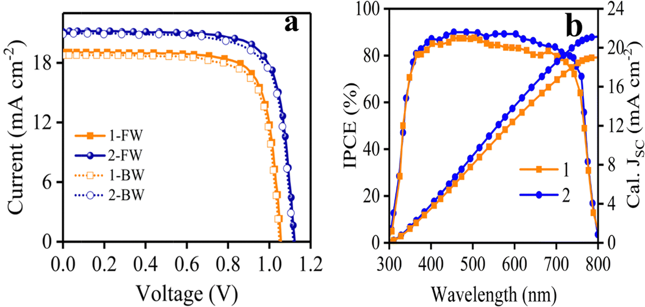 | ||
| Fig. 6 The curves of (a) J–V and (b) IPCE of the devices based on HTMs 1 and 2. | ||
| HTM | J SC (mA cm−2) | V OC (V) | FF (%) | PCE (%) |
|---|---|---|---|---|
| 1-FW | 19.05 | 1.05 | 0.76 | 15.20 |
| 1-BW | 18.76 | 1.04 | 0.75 | 14.63 |
| 2-FW | 21.12 | 1.12 | 0.77 | 18.21 |
| 2-BW | 20.88 | 1.11 | 0.76 | 17.61 |
The spectra of incident photon-to-current-conversion efficiency (IPCE) of 1- and 2-based devices are shown in Fig. 6b, which illustrate the same pattern. In particular, the integrated JSC of HTM 1 from the IPCE spectrum is 18.98 mA cm−2, which is consistent with the value achieved with the J–V curve of Fig. 6a (19.05 mA cm−2). Moreover, an important parameter to determine the commercialization feature of PSCs is their stability. The stability of photovoltaic performance of PSCs based on 1 and 2 was measured under the same conditions, in which 1 showed a similar performance in comparison with 2 as a reference, as shown in Fig. S5 in the ESI.† As shown in Fig. S5 (ESI†), the PCE curves obtained over time for HTMs 1 and 2 showed a mild slope to close down together by 750 h, following the PCE loss of about 33.4% and 20% from the initial values for HTMs 1 and 2, respectively, resulting in about 13.4% difference between the new HTM and the reference over 1000 h. Furthermore, the distribution of the photovoltaic parameters measured for 15 samples of PSCs fabricated with 1 and 2 are shown in Fig. 7, which shows the average PCEs of 13.58 and 16.44% for 1 and 2, respectively.
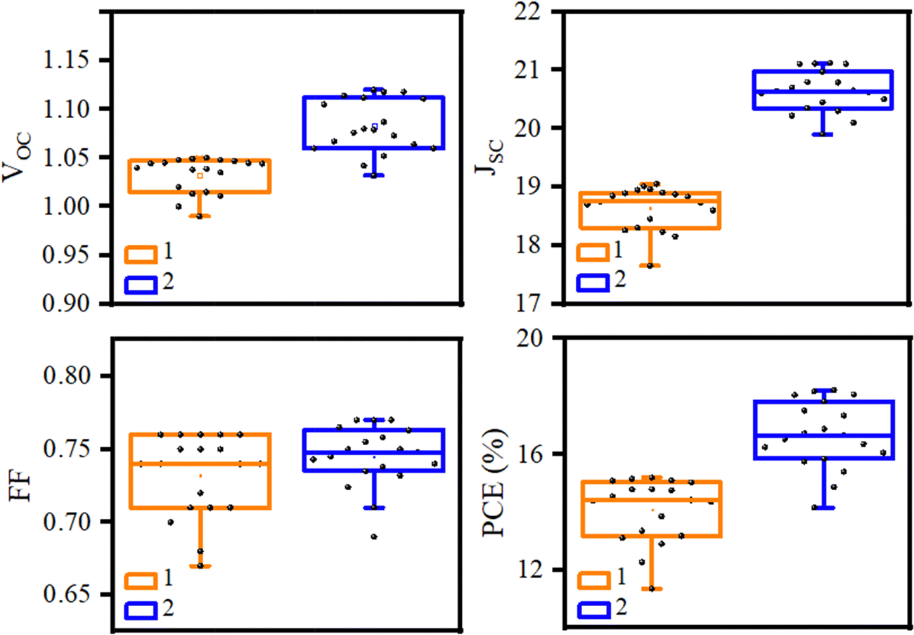 | ||
| Fig. 7 Tolerance of Voc, Jsc, FF, and PCE for 15 samples of PSCs fabricated with HTMs 1 and 2. | ||
Finally, the main advantage of 1 over 2 is the minimized cost, and the cost of synthesis of 1 gram of each of them is estimated at 1.66 and 273.62 $ g−1, respectively (Table 3). Moreover, the cost of 1 is among the lowestreported for HTMs used in PSCs, so far. As shown in Table 3, the price of HTM 1 is much lower than that of 2,11,46 which is a very suitable alternative to HTM 2 for the fabrication of cost-effective PSCs. In addition, the chemical waste produced during the synthesis of HTM 1 is negligible. Decreasing the cost of HTMs preparation depends on the number of synthesis steps and the used catalysts. In fact, for the synthesis of HTM 1, only one step was required, while 6 steps were employed to prepare HTM 2. Besides, the catalysts used to synthesize 2 ((Pd/2,2′-bis(diphenylphosphino)-1,1′-binaphthyl (BINAP)) are much more expensive and toxic, while preparing 2 does not require any catalyst.
| HTM | Steps | Material cost ($ g−1) | Cost per m2 ($ m−2) | Chemical waste (kg g−1) | Commercial price ($ g−1) |
|---|---|---|---|---|---|
| 1 | 1 | 1.66 | 0.2 | 0.04 (0.0) | — |
| 2 | 6 | 92 | 39.46 | 3.6 (1.0) | 170–425 |
The differences between synthesis cost and efficiency for different HTMs (ESI,† Table S2) are shown in Fig. 8, indicating the use of the new HTM in PSCs as a low-cost and economical HTM.
 | ||
| Fig. 8 Comparison chart of different reported HTMs (1–20) and new HTM (this work) based on cost and efficiency. The numbers and structures of HTMs are given in Table S3, ESI.† | ||
4. Conclusions
We synthesized a simple molecular HTM, 1, containing an imidazole unit using a simple chemical route for application in PSCs. The energy levels of the frontier orbitals of the targeted HTM are suitable for perovskite energy levels. In addition, its solubility in various organic solvents indicates it as an alternative for achieving efficient PSCs. Significantly, it revealed high thermal stability, impressive hydrophobic properties, and uniform morphology. Additionally, the synthesis of HTM 1 requires an extremely low cost (1.66 $ g−1) compared to 2 because its synthesis requires no catalysts and is one-step synthesis. The device fabricated with 1 displayed a high PCE of 15.20%, slightly less than that of 2 under similar conditions. These results show that 1 can be a low-cost alternative for the conventional expensive 2.Conflicts of interest
There are no conflicts to declare.Acknowledgements
The authors thank University of Zanjan for their support of this work.References
- H. Min, M. Kim, S.-U. Lee, H. Kim, G. Kim, K. Choi, J. H. Lee and S. I. Seok, Science, 2019, 366, 749–753 CrossRef CAS PubMed.
- F. Ye, W. Tang, F. Xie, M. Yin, J. He, Y. Wang, H. Chen, Y. Qiang, X. Yang and L. Han, Adv. Mater., 2017, 29, 1701440 CrossRef PubMed.
- M. A. Green, A. Ho-Baillie and H. J. Snaith, Nat. Photonics, 2014, 8, 506–514 CrossRef CAS.
- Z. Gevorkian, V. Gasparian and Y. Lozovik, Appl. Phys. Lett., 2016, 108, 051109 CrossRef.
- Y. Li, W. Yan, Y. Li, S. Wang, W. Wang, Z. Bian, L. Xiao and Q. Gong, Sci. Rep., 2015, 5, 14485 CrossRef CAS PubMed.
- S. Lv, Y. Song, J. Xiao, L. Zhu, J. Shi, H. Wei, Y. Xu, J. Dong, X. Xu and S. Wang, Electrochim. Acta, 2015, 182, 733–741 CrossRef CAS.
- Z. Yu and L. Sun, Adv. Energy Mater., 2015, 5, 1500213 CrossRef.
- Y. K. Wang, Z. C. Yuan, G. Z. Shi, Y. X. Li, Q. Li, F. Hui, B. Q. Sun, Z. Q. Jiang and L. S. Liao, Adv. Funct. Mater., 2016, 26, 1375–1381 CrossRef CAS.
- N. H. Tiep, Z. Ku and H. J. Fan, Adv. Energy Mater., 2016, 6, 1501420 CrossRef.
- Z. Yu and L. Sun, Small Methods, 2018, 2, 1700280 CrossRef.
- B. Pashaei, S. Bellani, H. Shahroosvand and F. Bonaccorso, Chem. Sci., 2020, 11, 2429–2439 RSC.
- H. D. Pham, T. C. J. Yang, S. M. Jain, G. J. Wilson and P. Sonar, Adv. Energy Mater., 2020, 10, 1903326 CrossRef CAS.
- Z. Shariatinia, Renewable Sustainable Energy Rev., 2020, 119, 109608 CrossRef CAS.
- L. Calió, S. Kazim, M. Grätzel and S. Ahmad, Angew. Chem., Int. Ed., 2016, 55, 14522–14545 CrossRef PubMed.
- S. Ryu, J. H. Noh, N. J. Jeon, Y. C. Kim, W. S. Yang, J. Seo and S. I. Seok, Energy Environ. Sci., 2014, 7, 2614–2618 RSC.
- A. Mei, X. Li, L. Liu, Z. Ku, T. Liu, Y. Rong, M. Xu, M. Hu, J. Chen and Y. Yang, Science, 2014, 345, 295–298 CrossRef CAS PubMed.
- L. Hajikhanmirzaei, H. Shahroosvand, B. Pashaei, G. D. Monache, M. K. Nazeeruddin and M. Pilkington, J. Mater. Chem. C, 2020, 8, 6221–6227 RSC.
- A. J. Huckaba, P. Sanghyun, G. Grancini, E. Bastola, C. K. Taek, L. Younghui, K. P. Bhandari, C. Ballif, R. J. Ellingson and M. K. Nazeeruddin, ChemistrySelect, 2016, 1, 5316–5319 CrossRef CAS.
- D. H. Sin, H. Hwang, S. Song and K. Cho, Org. Electron., 2020, 87, 105943 CrossRef CAS.
- L. Wang, Q. Zhuang, G. You, X. Lin, K. Li, Z. Lin, H. Zhen and Q. Ling, ACS Appl. Energy Mater., 2020, 3, 12475–12483 CrossRef CAS.
- Y. C. Chen, S. K. Huang, S. S. Li, Y. Y. Tsai, C. P. Chen, C. W. Chen and Y. J. Chang, ChemSusChem, 2018, 11, 3225–3233 CrossRef CAS PubMed.
- V. Thanikachalam, E. Sarojpurani and J. Jayabharathi, J. Photochem. Photobiol., A, 2017, 342, 59–77 CrossRef CAS.
- T. F. Markle, I. J. Rhile, A. G. DiPasquale and J. M. Mayer, Proc. Natl. Acad. Sci. U. S. A., 2008, 105, 8185–8190 CrossRef CAS PubMed.
- J. Tagare, D. K. Dubey, J.-H. Jou and S. Vaidyanathan, Dyes Pigm., 2019, 160, 944–956 CrossRef CAS.
- B. N. Bideh, C. Roldan-Carmona, H. Shahroosvand and M. K. Nazeeruddin, Dalton Trans., 2016, 45, 7195–7199 RSC.
- B. Nemati Bideh and H. Shahroosvand, New J. Chem., 2020, 44, 1881–1887 RSC.
- A. O. Eseola, O. Adepitan, H. Görls and W. Plass, New J. Chem., 2012, 36, 891–902 RSC.
- Q.-Y. Yu, J.-F. Huang, Y. Shen, L.-M. Xiao, J.-M. Liu, D.-B. Kuang and C.-Y. Su, RSC Adv., 2013, 3, 19311–19318 RSC.
- B. N. Bideh and H. Shahroosvand, Dalton Trans., 2022, 51, 3652–3660 RSC.
- B. Nemati Bideh, H. Shahroosvand and M. K. Nazeeruddin, Inorg. Chem., 2021, 60, 11915–11922 CrossRef CAS PubMed.
- T. Leijtens, I.-K. Ding, T. Giovenzana, J. T. Bloking, M. D. McGehee and A. Sellinger, ACS Nano, 2012, 6, 1455–1462 CrossRef CAS PubMed.
- K. Rakstys, A. Abate, M. I. Dar, P. Gao, V. Jankauskas, G. N. Jacopin, E. Kamarauskas, S. Kazim, S. Ahmad and M. Grätzel, J. Am. Chem. Soc., 2015, 137, 16172–16178 CrossRef CAS PubMed.
- M.-C. Jung and Y. Qi, Org. Electron., 2016, 31, 71–76 CrossRef CAS.
- A. M. Leguy, Y. Hu, M. Campoy-Quiles, M. I. Alonso, O. J. Weber, P. Azarhoosh, M. Van Schilfgaarde, M. T. Weller, T. Bein and J. Nelson, Chem. Mater., 2015, 27, 3397–3407 CrossRef CAS.
- L. Zheng, Y.-H. Chung, Y. Ma, L. Zhang, L. Xiao, Z. Chen, S. Wang, B. Qu and Q. Gong, Chem. Commun., 2014, 50, 11196–11199 RSC.
- B. Hailegnaw, S. Kirmayer, E. Edri, G. Hodes and D. Cahen, J. Phys. Chem. Lett., 2015, 6, 1543–1547 CrossRef CAS PubMed.
- J. Zhang, B. Xu, L. Yang, C. Ruan, L. Wang, P. Liu, W. Zhang, N. Vlachopoulos, L. Kloo and G. Boschloo, Adv. Energy Mater., 2018, 8, 1701209 CrossRef.
- M.-H. Li, C.-W. Hsu, P.-S. Shen, H.-M. Cheng, Y. Chi, P. Chen and T.-F. Guo, Chem. Commun., 2015, 51, 15518–15521 RSC.
- F. J. Ramos, K. Rakstys, S. Kazim, M. Grätzel, M. K. Nazeeruddin and S. Ahmad, RSC Adv., 2015, 5, 53426–53432 RSC.
- Z. Zhu, Y. Bai, H. K. H. Lee, C. Mu, T. Zhang, L. Zhang, J. Wang, H. Yan, S. K. So and S. Yang, Adv. Funct. Mater., 2014, 24, 7357–7365 CrossRef CAS.
- M. Saliba, S. Orlandi, T. Matsui, S. Aghazada, M. Cavazzini, J.-P. Correa-Baena, P. Gao, R. Scopelliti, E. Mosconi and K.-H. Dahmen, Nat. Energy, 2016, 1, 15017 CrossRef CAS.
- B. Xu, H. Tian, L. Lin, D. Qian, H. Chen, J. Zhang, N. Vlachopoulos, G. Boschloo, Y. Luo and F. Zhang, Adv. Energy Mater., 2015, 5, 1401185 CrossRef.
- K. Rakstys, S. Paek, P. Gao, P. Gratia, T. Marszalek, G. Grancini, K. T. Cho, K. Genevicius, V. Jankauskas and W. Pisula, J. Mater. Chem. A, 2017, 5, 7811–7815 RSC.
- C. H. Teh, R. Daik, E. L. Lim, C. C. Yap, M. A. Ibrahim, N. A. Ludin, K. Sopian and M. A. M. Teridi, J. Mater. Chem. A, 2016, 4, 15788–15822 RSC.
- B. Xu, E. Sheibani, P. Liu, J. Zhang, H. Tian, N. Vlachopoulos, G. Boschloo, L. Kloo, A. Hagfeldt and L. Sun, Adv. Mater., 2014, 26, 6629–6634 CrossRef CAS PubMed.
- B. Pashaei, H. Shahroosvand, M. Ameri, E. Mohajerani and M. K. Nazeeruddin, J. Mater. Chem. A, 2019, 7, 21867–21873 RSC.
Footnote |
| † Electronic supplementary information (ESI) available. See DOI: https://doi.org/10.1039/d3ya00111c |
| This journal is © The Royal Society of Chemistry 2023 |