
In vivo and In vitro properties evaluation of curcumin loaded MgO doped 3D printed TCP scaffolds†
Arjak
Bhattacharjee
 ,
Yongdeok
Jo
and
Susmita
Bose
*
,
Yongdeok
Jo
and
Susmita
Bose
*
W. M. Keck Biomedical Materials Research Laboratory School of Mechanical and Materials Engineering Washington State University, Pullman, Washington 99164, USA. E-mail: sbose@wsu.edu
First published on 19th April 2023
Abstract
The lack of site-specific chemotherapeutic agents to treat bone malignancy throws a significant challenge in the design of a delivery vehicle. The major scientific question posed in this study is, can we utilize curcumin-loaded magnesium oxide (MgO) doped 3D printed tricalcium phosphate (TCP) bone grafts as a localized delivery system that improves early stage in vivo osseointegration and in vitro chemoprevention, antibacterial properties? We have utilized curcumin as an alternative natural chemopreventive agent for bone cancer-specific delivery after direct incorporation on the 3D printed tricalcium phosphate (TCP) bone grafts. The addition of MgO as a dopant to TCP leads to ∼1.3 times enhancement in compressive strength. The designed drug delivery system shows up to ∼22% curcumin release in a physiological pH of 7.4 after 30 days. The presence of curcumin leads to up to ∼8.5 times reduction in osteosarcoma viability. In vitro results indicate that these scaffolds significantly enhance bone-forming osteoblast cells while reducing the bone-resorbing osteoclast cells. The in vivo rat distal femur model surgery followed by histological assessment with H&E, vWF, and Movat pentachrome staining results show that the designed scaffolds lead to new bone formation (up to ∼2.5 times higher than the control) after successful implantation. The presence of MgO and curcumin results in up to ∼71% antibacterial efficacy against osteomyelitis causing S. aureus. These 3D printed osteogenic and chemopreventive scaffolds can be utilized in patient-specific low load-bearing defect sites.
1. Introduction
Increasing demand for musculoskeletal reconstruction among younger adults globally fuels the need to develop an alternate strategy for designing artificial bone grafts with longer service life.1,2 The major causes of skeletal reconstruction are bone disorders, trauma, birth defects, and bone cancers.3 Osteosarcoma is the most common type of bone malignancy for pediatric patients and younger adults.4 The current treatment approaches for osteosarcoma consist of chemotherapy and surgical removal of the affected bone segment.5 However, the large defects after surgical removal of osteosarcoma are beyond the bone's self-healing capacity and need to be reconstructed utilizing an artificial bone graft.6,7 There is a need to develop a multifunctional bone graft that can have the dual properties of chemoprevention and new bone formation after osteosarcoma surgery.8Naturopathy is currently gaining importance in the medical community across the globe owing to its abundance and safety compared to commercial alternatives.9 The ancient Indian medical literature Ayurveda reports the use of curcumin from turmeric (Curcuma longa) as an important herbal medicine for immunity boosting, wound healing, infection control, diabetes management, and treating bone fractures.10 Few recent works report that curcumin has chemopreventive potential.11 However, a significant knowledge gap in the existing literature demonstrates the dual effects of curcumin-loaded 3D printed bone grafts for early-stage in vivo osseointegration and in vitro chemoprevention. Our work aims to bridge this gap by directly incorporating curcumin into 3D printed ceramic bone grafts.
3D printing is currently the only advanced fabrication technology that can produce patient-specific and defect-specific bone grafts with complex designs and porosity.12,13 The presence of pores allows nutrient supply to the newly formed bone after implantation.14,15 Tricalcium phosphate (TCP) is the widely used ceramic for 3D printed bone grafts due to its compositional and chemical similarities with human hard tissues.16,17 However, the poor mechanical strength of the grafts often hinders new bone formation in vivo. Doping TCP with magnesium oxide (MgO) leads to the higher compressive strength of the scaffolds due to grain boundary strengthening effects.18,19 It further helps in vivo osteogenesis.20 The success of a bone graft is dependent on its new bone-forming ability after implantation.21 Additionally, drug delivery to a specific surgical site is challenging.22 Hence, localized drug delivery from 3D printed grafts is gaining momentum in the bone research community due to its advantages of site-specific actions.23
We have designed a localized delivery system with 3D printed MgO-TCP-curcumin that promotes new bone formation after implantation in a rat distal femur model. The designed grafts can serve the dual function of new bone formation and chemoprevention. The osteogenic ability of a bone graft is assessed by either its role in enhancing the bone-forming osteoblast cells or inhibiting the bone-eating osteoclast cells. Our strategy is to assess the potential of the designed system in new bone formation by investigating its effects on both osteoblast viability and osteoclast inhibition.24,25 Early-stage osseointegration after in vivo implantation is the most crucial factor that determines the long-term success of a bone graft.26 Due to limited works performed to assess the early-stage osseointegration of localized drug delivery systems, containing natural medicinal compounds, it is important to investigate the bone formation ability of these grafts in vivo. We have studied the in vivo bone formation potential of this designed delivery system using rat distal femur models.27
The bacterial attachment on the graft surface is one of the important causes of graft failure after implantation.28,29 Bacterial adhesion on the implant surface often results in the formation of biofilm, which is difficult to treat with conventional treatments.30 Implant failure due to bacterial infection caused by S. aureus may need to be rectified by costlier and more complex revision surgeries. Antibiotic delivery to the specific surgical site is challenging.31,32 Additionally, an emerging challenge in infection control is multi-drug resistance bacteria.33–35 Natural medicinal compounds and transition metals pose an advantage in this regard. 3D printed bone grafts with inherent antibacterial properties reduce the chances of post-surgical bacterial infection.
The objective of our study is to investigate the in vivo osteogenesis, in vitro chemopreventive potential, and antibacterial properties of the 3D printed MgO-TCP grafts containing curcumin. We hypothesize that the presence of MgO and curcumin will enhance in vitro osteoblast viability, inhibit osteoclast proliferation and osteosarcoma viability, and incorporate antibacterial properties. The utilization of this composite system is expected to enhance in vivo bone regeneration in rat distal femur models. The novelty of this work lies in the direct incorporation of curcumin into the 3D printed MgO-TCP grafts that show enhanced multifunctional biological properties. The potential of the fabricated grafts is characterized by in vitro osteoblast, osteoclast, and osteosarcoma culture, resorption pit formation study, and antibacterial efficacy assessment against S. aureus and P. aeruginosa. The novel 3D printed scaffold-based drug delivery system design leads to enhanced in vivo bone regeneration and blood vessel formation, as evident in rat distal model femur model surgery and histological assessment with H&E staining, and vWF staining. These bone grafts are expected to find application in low load-bearing defect repair sites.
2. Materials and methods
2.1 Substrate preparation
To prepare the 3D printed structures, the β-TCP powder was made using a previously reported method by our group.36 Dicalcium phosphate (calcium phosphate dibasic, CaHPO4, ≥98.0%, Millipore Sigma, St. Louis, USA) and calcium carbonate (CaCO3, ≥99.0%, Millipore Sigma, St. Louis, USA) were mixed at a 2![[thin space (1/6-em)]](https://www.rsc.org/images/entities/char_2009.gif) :1 molar ratio followed by 2 h of ball milling at speed 70, in presence of zirconia milling media. The ball:powder ratio was used as 2:1 w/w. Calcination of the ball-milled powder was done for 24 h at 1050 °C. The calcined powder was then wet milled for 2 h using 1.5× w/v of ethanol with a milling media-to-powder ratio of 2× w/w. In the next step, ethanol was evaporated, followed by washing the dried powder with deionized water to remove impurities, followed by drying. To dope MgO in the obtained TCP powder, 1 wt% of MgO (≥99.99%, Millipore Sigma, St. Louis, USA) was mixed with the powder followed by 2 h ball milling at speed 70 (powder:ball ratio of 2:1). The dopant amount was selected based on our previous optimization results on the mechanical and biological properties of MgO-doped TCP.18,19 The obtained pure β-TCP and MgO doped β-TCP powders were further heat treated at 250 °C for the removal of chemisorbed moisture. These dried and moisture-removed powder was utilized to fabricate 3D printed scaffolds without any designed porosity, using a binder jet 3D printing machine (ExOne LLC, Irwin, PA, USA). SolidWorks was utilized to design the CAD files of these structures and converted them to a.stl file, followed by feeding them into the 3D printer. Circular scaffolds with 5 mm diameter and 3 mm height were utilized for in vitro studies. Cylindrical scaffolds with a dimension of 11 mm in height and 7 mm in diameter were used for compressive strength assessment. For in vivo assessment, cylindrical scaffolds with 2.5 mm diameter and 4 mm height were fabricated as per the surgery protocol. Crack-free parts were printed by ensuring careful parametric optimizations. The recoat speed was utilized as 10 m s−1 with 7 s curing time, a layer thickness of 60 μm, and a binder saturation of 92. Curing of the 3D printed green scaffolds was done at 175 °C for 1.5 h. In the next step, the loosely adherent powders were removed by compressed air, followed by sintering at 1250 °C for 2 h.1,37 The control samples are named TCP, MgO-doped ones are represented as Mg-TCP, and the curcumin-loaded scaffolds are denoted as Mg-TCP-Cur throughout the manuscript.
:1 molar ratio followed by 2 h of ball milling at speed 70, in presence of zirconia milling media. The ball:powder ratio was used as 2:1 w/w. Calcination of the ball-milled powder was done for 24 h at 1050 °C. The calcined powder was then wet milled for 2 h using 1.5× w/v of ethanol with a milling media-to-powder ratio of 2× w/w. In the next step, ethanol was evaporated, followed by washing the dried powder with deionized water to remove impurities, followed by drying. To dope MgO in the obtained TCP powder, 1 wt% of MgO (≥99.99%, Millipore Sigma, St. Louis, USA) was mixed with the powder followed by 2 h ball milling at speed 70 (powder:ball ratio of 2:1). The dopant amount was selected based on our previous optimization results on the mechanical and biological properties of MgO-doped TCP.18,19 The obtained pure β-TCP and MgO doped β-TCP powders were further heat treated at 250 °C for the removal of chemisorbed moisture. These dried and moisture-removed powder was utilized to fabricate 3D printed scaffolds without any designed porosity, using a binder jet 3D printing machine (ExOne LLC, Irwin, PA, USA). SolidWorks was utilized to design the CAD files of these structures and converted them to a.stl file, followed by feeding them into the 3D printer. Circular scaffolds with 5 mm diameter and 3 mm height were utilized for in vitro studies. Cylindrical scaffolds with a dimension of 11 mm in height and 7 mm in diameter were used for compressive strength assessment. For in vivo assessment, cylindrical scaffolds with 2.5 mm diameter and 4 mm height were fabricated as per the surgery protocol. Crack-free parts were printed by ensuring careful parametric optimizations. The recoat speed was utilized as 10 m s−1 with 7 s curing time, a layer thickness of 60 μm, and a binder saturation of 92. Curing of the 3D printed green scaffolds was done at 175 °C for 1.5 h. In the next step, the loosely adherent powders were removed by compressed air, followed by sintering at 1250 °C for 2 h.1,37 The control samples are named TCP, MgO-doped ones are represented as Mg-TCP, and the curcumin-loaded scaffolds are denoted as Mg-TCP-Cur throughout the manuscript.
2.3 X-ray diffraction (XRD) study
The doped and undoped TCP were characterized by X-Ray diffraction (Rigaku Miniflex 600) in the range of 20° to 50° (step size of 0.05°) with a Cu Kα radiation source (40 kV, and 30 mA).2.4 Drug loading and release
In vitro release of curcumin was quantified in phosphate buffer solution (PBS) at pH 7.4 and acetate buffer solution at pH 5.0 for 30 days. The pH 7.4 was selected to mimic the physiological pH, whereas the pH 5.0 was selected to mimic the pH of postsurgical microenvironments.38 The curcumin (≥98.0% Millipore Sigma, St. Louis, USA) was dissolved in pure ethanol and this solution was pipetted on top of the scaffolds for curcumin loading. Samples containing 500 μg of curcumin were kept in glass vials with 4 mL of the buffer, followed by shaking (150 rpm) at 37 °C inside a shaker. After collecting data at each time point, the buffer was taken out and fresh buffer solution was put in the vials. To quantify the curcumin release, the optical density of 100 μL of the collected buffer was measured at 427 nm utilizing Biotek (VT, USA) Synergy 2 SLFPTAD microplate reader. To calculate the cumulative release of curcumin (%), one standard calibration curve was made with the obtained data from curcumin release with different concentrations. The release kinetics was modeled with the Weibull model (using MATLAB 2021b), as mentioned in the following equation| Y(t) = 100 × {1 − exp [−(t/b)a]} | (1) |
In this equation, the drug release rate (%) is represented as “Y(t)”, while “t” is the time in days. The time constant is denoted by “b” and the shape parameter is denoted by “a”.39
2.5. In vitro cell–material interaction
In vitro, cell–material interactions were assessed by osteoblast, osteoclast, and osteosarcoma cell cultures. The composition for detailed in vitro cell culture studies was selected based on the initial optimization results with day-5 osteoblast and osteosarcoma cell viability studies. Different amounts of curcumin (100 μg, 200 μg, 400 μg, 1000 μg, and 1500 μg) were loaded on the TCP scaffolds for the initial studies. These samples are noted as Cur 1, Cur 2, Cur 3, Cur 4, and Cur 5 respectively. The cell culture experimental methods are provided below.000 cells per sample. The growth media consists of Roswell Park Memorial Institute (RPMI)-1640, 0.05 mM 2-mercaptoethanol, and 10% FBS. The growth media was altered to differentiation media for the rest of the culture period. The differentiation media contains 40 ng mL−1 phorbol 12-myristate 13-acetate (Millipore Sigma, St. Louis, USA) and 10 ng mL−1 receptor activator of the nuclear factor κ-B ligand (RANKL) including RPMI-1640 and FBS. After the addition of the media, the well plate incubation was done at 37 °C in a 5% CO2 atmosphere. The media change was done each 3 days. Tartrate-resistant acid phosphatase (Acid Phosphatase Assay Kit, abcam, USA) was carried out to analyze the cellular behavior after each time point. To analyze the resorption pits after 11 days and 21 days of culture, the sample ultrasonication was done in 1 mL of 1 M NaCl solution and 0.2% Triton X-100 mixture. In the next step, the samples were washed with ethanol followed by ethanolic dehydration series. The pit formations were investigated by imaging the samples in a scanning electron microscope (FESEM) after gold sputter coating. The live-dead staining was performed by pouring 800 μL of 1:1 mixture of calcein M (Biolegend, CA, USA) and propidium iodide (Invitrogen, MA, USA) solution (in PBS) on every sample. Confocal microscopy (TCS SP5 confocal laser microscope) was done on the stained samples to detect the live and dead cells using the lasers at 485–535 nm and 630–720 nm respectively.41 FESEM imaging of the attached cells was carried out to check the cellular morphology.
:1 mixture. The supplemental media consists of 2.5 mM sterilized L-glutamine (without phenol red) solution, fetal bovine serum (10% FBS, ATCC, Manassas, USA), 0.3 mg mL−1 G418 (Millipore Sigma, St. Louis, USA), and 0.1% penicillin–streptomycin (Millipore Sigma, St. Louis, USA). The sterilized samples were put on a 24-well plate followed by the addition of 40 × 103 cells per sample. After this, 1 mL of cell culture media was poured into each well. In the next step, the well plates were incubated at 34 °C under a 5% CO2 atmosphere. The MTT assay [3-(4,5-dimethylthiazol-2-yl)-2,5-diphenyltetrazolium bromide, Millipore Sigma, USA] was performed after 3, 5, 7, and 11 days of culture. To carry out the assay, 100 μL of MTT solution was poured on top of each sample, then 900 μL of media was put and the samples were incubated at 34 °C for 2 h. After the incubation period, this solution was removed and 600 μL of solubilizer (10% Triton X-100, 0.1 N HCl, and isopropanol) was poured into each well for dissolving the formazan crystals. 100 μL of this solution was transferred to a 96-well plate and the reading was taken at 570 nm using a UV-VIS microplate reader.
The cellular morphology was investigated using FESEM (FEI Inc., Hillsboro, OR USA). Before the imaging, the samples after cell culture were fixed with 2% paraformaldehyde and 2% glutaraldehyde in 0.1 M phosphate buffer and kept inside the refrigerator overnight at 4 °C. After this, sample rinsing was done 3 times with 0.1 M phosphate buffer solution and the samples were post-fixed using 2% osmium tetroxide (OsO4). The sample dehydration was carried out in an ethanolic series ranging from 30% to 90% once and three times with 100% ethanol. In the next step, hexamethyldisilane (HMDS) was poured into each sample followed by overnight drying. The samples were gold coated before taking the FESEM images.
000–40000 cells per sample. The MTT assay and assessment of cellular morphology by FESEM were done with a similar method that was done for the osteoblasts.
2.6. Assessment of antibacterial efficacy
The antibacterial potential of the prepared compositions was assessed against S. aureus and P. aeruginosa based on the modified ISO 22196:2011 Standard.12,42 Freeze-dried bacteria (Carolina Biological, USA) were activated as per the manufacturer's recommendations. The optical density of the activated bacterial solution was computed at 625 nm with a UV-Vis microplate reader (BioTek) and compared with the McFarland standard. After sterilization, the scaffolds were placed in a 24-well plate and 106 CFU of activated bacteria was put on top of each scaffold followed by 1 mL of broth media addition. In the following step, the well plates were transferred inside an incubator at 37 °C and 90% humidity for 36 h and 72 h. After the sample–bacteria interaction, the tested scaffolds were placed into a glass vial with 1 mL PBS. In the next step, 10 μL of the diluted vortexed bacterial suspension was put on each agar plate and incubation was done for 24 h at 37 °C. The bacterial colonies were quantified from the agar plate photographs. Tryptic soy agar plates (G204, Hardy Diagnostics, USA) were utilized to plate S. aureus, whereas pseudosel agar (cetrimide agar) plates (BD 297882, VWR, USA) were used to plate P. aeruginosa. The bacterial cell viability was quantified with the following equation. The bacterial efficacy of the treatments was computed as 100 – bacterial cell viability (%).| Bacterial cell viability (%) = Ntreatment/Ncontrol × 100% | (2) |
In the above equation, Ntreatment and Ncontrol are the bacterial colonies formed on the agar plates of treatments and control respectively after each time point. The bacterial attachment on top of each sample was analyzed with FESEM using a similar protocol that was carried out for the osteoblasts.
2.7 In vivo properties assessment of the fabricated scaffolds
These samples were stained with Hematoxylin [Millipore Sigma (H3136), St. Louis, USA] & Eosin [Surgipath, Leica, Buffalo Grove, USA] (H&E) staining and von Willebrand factor (vWF) staining with blood vessel staining kit (ECM 590, Millipore Sigma, USA) to quantify the new bone formation and blood vessel formation respectively.47–49 As per the manufacturer's recommendation, the primary antibody in the vWF was utilized as a rabbit anti-vWF polyclonal antibody, and the antigen retrieval was performed with a steamer at 60 °C utilizing PBS. Selected samples were further characterized with Movat pentachrome staining (Abcam, USA).50–52 The slides after staining were imaged with high-magnification optical images. To quantify the new bone surrounding the implant–bone interface, RGB analysis, and area measurement methods were utilized using ImageJ software.
3. Results
The XRD results of undoped and MgO doped TCP after sintering are shown in Fig. S1 (ESI†). Predominantly β – TCP (JCPDS # 09-0169) phases are present in the sintered TCP with some α – TCP (JCPDS # 09-0348) peaks. MgO doping further increases the formation of β – TCP and only corresponding β – TCP peaks are noticed. Similar observations are reported in our previous work.18 The schematic of the binder jet 3D printing machine utilized to fabricate the scaffolds and different types of scaffolds such as circular, and cylindrical scaffolds with and without any designed porosity are shown in Fig. 1(a). Fig. 1(b) shows that at pH 7.4, ∼22% curcumin is released in the buffer from the TCP scaffolds, whereas ∼17% of release is observed from the Mg-TCP scaffold surface after 30 days. Fig. 1(c) shows the Weibull model fitting of the first 24 h drug release data at pH 7.4. The results indicate a good fitting with an R2 value > 0.9. Fig. 1(d) shows curcumin release at pH 5. A total of 30% release is observed from the TCP surface, whereas the MgO-doped 3D printed scaffolds show a total release of ∼23% release respectively after 30 days. Fig. 1(e) shows the Weibull model fitting of the first 24 h drug release data at pH 5.0. The obtained fitting results indicate a good fitting with an R2 value > 0.9. The fitting data after 30 days of drug release is shown in Fig. S2 (ESI†). Table S1 (ESI†) shows the values of the time constant and shape parameters as obtained from the fitting data. For the release study at pH 7.4, the TCP-Cur fitting shows the parametric values as “a” 3.5, “b” 1.2, the Mg-TCP-Cur shows values as “a” 3.4, “b” 1.6; the parametric values after fitting the pH 5.0 release data of TCP-Cur shows the parametric values as “a” 6.9, “b” 3.8 and the fitting results of Mg-TCP-Cur release at pH 5.0 shows the values as “a” 6.7, “b” 5.0. The FESEM images before and after drug release are shown in Fig. 1(f)–(k). The surfaces after drug release at pH 5.0 (Fig. 1(j) and (k)) show generation of porosity and higher degradation as compared to the surfaces at pH 7.4 (Fig. 1(h) and (i)). The degradation areas in the FESEM images are identified with an arrow in the figures. The scaffold surfaces before the drug release study are shown in Fig. 1(f) and (g). Initial cell viability results with different amounts of curcumin after interaction with osteoblast and osteosarcoma cells for 5 days are shown in Fig. S3 and S4 (ESI†) respectively. Curcumin amount of 400 μg leads to a significant increase in osteoblast cellular viability, whereas a curcumin amount of 1000 μg and 1500 μg results in cytotoxicity (Fig. S3, ESI†). Fig. S4 (ESI†) shows that increasing the amount of curcumin leads to a significant reduction in osteosarcoma viability. The highest osteosarcoma reduction is noticed for the composition of 1500 μg curcumin. Based on these results, a curcumin amount of 500 μg is selected for a detailed in vitro study. The interactions of osteoblast with the 3D printed scaffolds are shown in Fig. 2(a) and (b). The cytocompatibility of the utilized compositions is validated on day 3, as per the ISO 10993 standard.53 The MTT assay results (Fig. 2(a)) show that on day 3, the cellular viability of Mg-TCP and Mg-TCP-Cur enhance slightly than the control. The cell viability of treatment samples significantly enhances on day 7 and day 11. The Mg-TCP shows ∼1.2 times higher viability and the Mg-TCP-Cur shows ∼1.4 times higher osteoblast viability. The FESEM images (Fig. 2(c)) show good cellular attachment and extended filopodial attachment. The interactions of osteoclasts with the 3D printed scaffolds are shown in Fig. 3(a)–(c). The TRAP assay results (Fig. 3(a)) indicate that both treatments lead to a significantly lesser cellular viability than the control. The Mg-TCP leads to ∼1.3 times lower cell viability than the control on day 11, whereas the Mg-TCP-Cur results in ∼2.9 times reduced cellular viability. The Mg-TCP-Cur shows ∼2.5 times reduced cell viability on day 21 than that of the control. The resorption pit analysis (Fig. 3(b)) shows a significantly higher pit formation in the control TCP than in both Mg-TCP and Mg-TCP-Cur. All the tested compositions are covered with a dense apatite layer at each time point. This trend is further confirmed with the FESEM and confocal images (Fig. 3(c)) on day 21. The cells are noticed as embedded within the apatite layer, formed on top of each sample surface. The treatment samples show a significantly lesser presence of cells within the apatite layer. The confocal microscopic images show a significant number of live osteoclast cells (green dots). In contrast, the treatment samples show mostly dead cells (red dots) and only a few live cells. The osteosarcoma cell viability assessment results are presented in Fig. 4(a)–(c). The Mg-TCP-Cur composition shows ∼1.3 times reduced cell viability than the control sample on day 3. On day 7, this composition shows a cell viability reduction of ∼4 times, which further enhances to ∼8.5 times on day 11. The FESEM images are shown in Fig. 4(b). The control samples show healthy osteosarcoma cell attachment with filopodial extension. In contrast, damaged filopodia are noticed in the Mg-TCP-Cur sample. Fig. 4(c) shows the schematic of the osteoblast viability, osteoclast inhibition, and osteosarcoma inhibition on the 3D printed Mg-TCP-Cur scaffold surface. The antibacterial properties assessment results after 36 h and 72 h sample-bacterial interactions are shown in Fig. 5. The agar plate images (Fig. 5(a)) indicate that Mg-TCP and Mg-TCP-Cur lead to a significant S. aureus bacterial colony reduction than that of the control sample. The bacterial cell viability quantification (Fig. 5(b)) indicates that the Mg-TCP composition shows the highest ∼33% antibacterial efficacy and the Mg-TCP-Cur composition shows the highest ∼71% antibacterial efficacy in comparison to the control. The corresponding FESEM images in Fig. 5(c) show a lesser bacterial density in the treatment sample than that of the control. Inset FESEM image of the Mg-TCP-Cur composition shows bacterial cell debris, which arises due to the puncture of bacterial cells in presence of Mg2+ and curcumin. Agar plate results (Fig. 5(d)) after 72 h of interaction between fabricated scaffolds and P. aeruginosa show a significant reduction in bacterial colonies in the Mg-TCP-Cur composition, compared to the control TCP. The corresponding FESEM images (Fig. 5(e)) show that control TCP has dense bacterial colonies, which significantly reduces in presence of curcumin and MgO. Dilated bacterial cell walls are noticed in the treatment sample. The high magnification inset image of Mg-TCP-Cur shows debris, resulting due to bacterial killing. The agar plate quantification results are shown in Fig. 5(f). Mg-TCP-Cur leads to ∼79% antibacterial efficacy against P. aeruginosa after 72 h. The antibacterial mechanism of Mg-TCP-Cur composition is schematically shown in Fig. 5(g).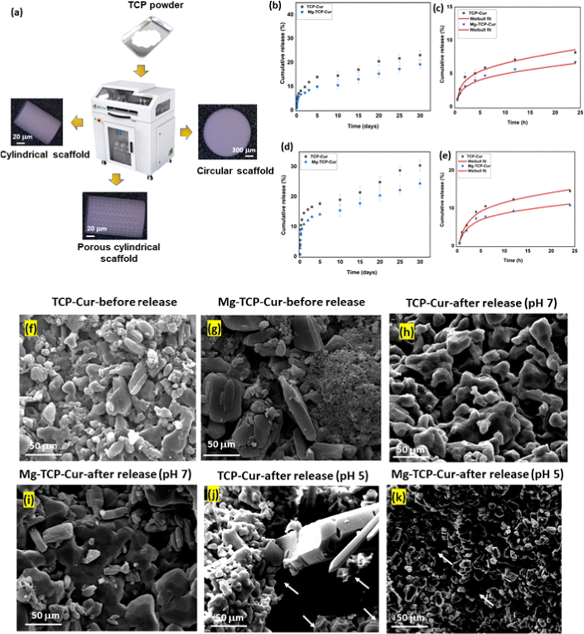 | ||
| Fig. 1 (a) Schematic of the binder jet 3D printing machine used to construct the scaffolds and various designs of scaffolds such as circular, cylindrical scaffolds without any designed porosity, and porous cylindrical scaffolds. (b) Cumulative release of curcumin from 3D printed TCP scaffolds and MgO-doped 3D printed TCP scaffolds at pH 7.4 shows 22% and 17% release respectively after 30 days. (c) Weibull model fitting of the first 24 h drug release data at pH 7.4. (d) Cumulative release of curcumin from 3D printed TCP scaffolds and MgO-doped 3D printed TCP scaffolds at pH 5 shows 30% and 23% release respectively after 30 days. (e) Weibull model fitting of the first 24 h drug release data at pH 5. (f and g) FESEM images of the TCP-Cur and Mg-TCP-Cur substrates before drug release study. (h and i) FESEM images of the TCP-Cur and Mg-TCP-Cur substrates after drug release study at pH 7.4. (j and k) FESEM images of the TCP-Cur and Mg-TCP-Cur substrates after drug release study at pH 5.0. The degraded regions in scaffolds after drug release at pH 5.0 is marked with arrows in Fig. 1(j) and (k). | ||
 | ||
| Fig. 2 Interactions of osteoblast with 3D printed scaffolds (a) MTT assay results show that the tested compositions are cytocompatible. On day 3, Mg-TCP and Mg-TCP-Cur show slightly higher cellular viability than the control. On day 7 and day 11, the treatment samples indicate significantly enhanced cell viability than the control. The Mg-TCP sample shows ∼1.2 times enhancement, the Mg-TCP-Cur shows ∼1.4 times enhancement than the control. In the image, * indicates a p value of <0.05 and the ** denotes a p value of <0.0001. (b) Good cellular attachment on each sample surface is seen in the FESEM images. The treatment samples show the presence of extended filopodial attachment. The observed cells and extended filopodia are marked with the dotted circle in the images. | ||
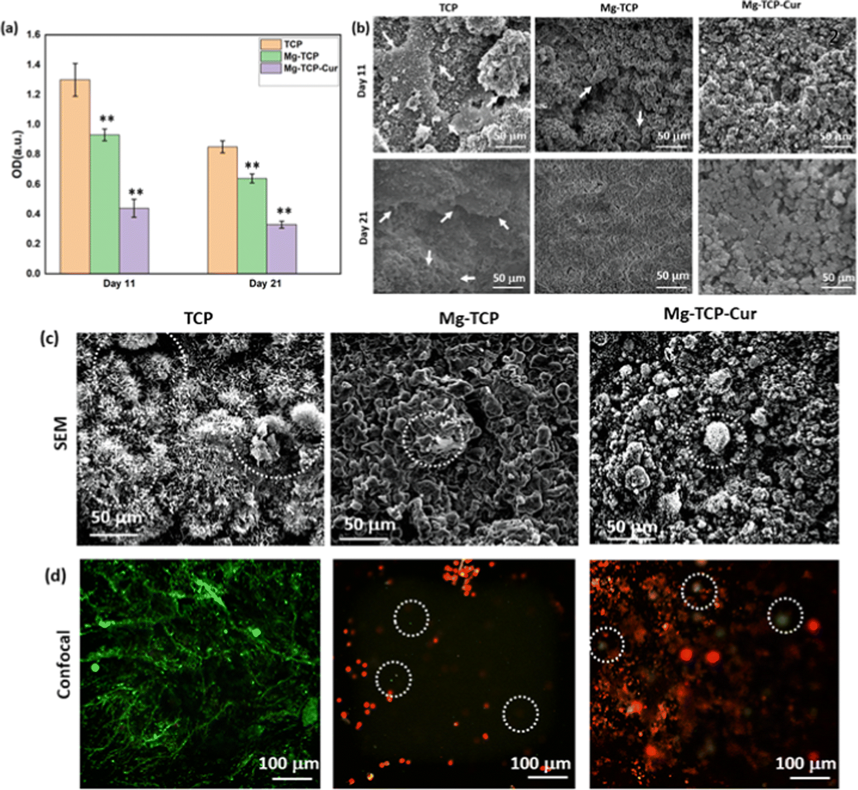 | ||
| Fig. 3 Interactions of osteoclasts with the 3D printed scaffolds (a) TRAP assay results indicate that the treatment samples show a significant reduction in osteoclast viability than the control. On day 11, the Mg-TCP shows ∼1.3 times reduction in cell viability, and the Mg-TCP-Cur shows ∼2.9 times reduction in cell viability. On day 21, the Mg-TCP-Cur shows ∼2.5 times reduction in cell viability than that of the control. (b) The resorption pit analysis shows significant pit formation in the control sample, but the treatment samples show a lesser amount of pit formation. The generated pit regions are marked with the arrows in the FESEM images. The samples are covered with the apatite layer at both time points. (c) The FESEM and confocal microscopic images of osteoclasts on day 21. The FESEM images show that the samples are covered with the apatite layer. The embedded cells within the layers are identified with a dotted circle. In contrast, the treatment samples show a lesser density of cells embedded within the apatite layer. The confocal microscopic images indicate that the control sample has mostly live osteoclast cells (green dots), whereas the treatment samples show mostly the presence of dead cells (red dots). Some live cells are visible in the treatment samples and pointed with a dotted circle in the images. | ||
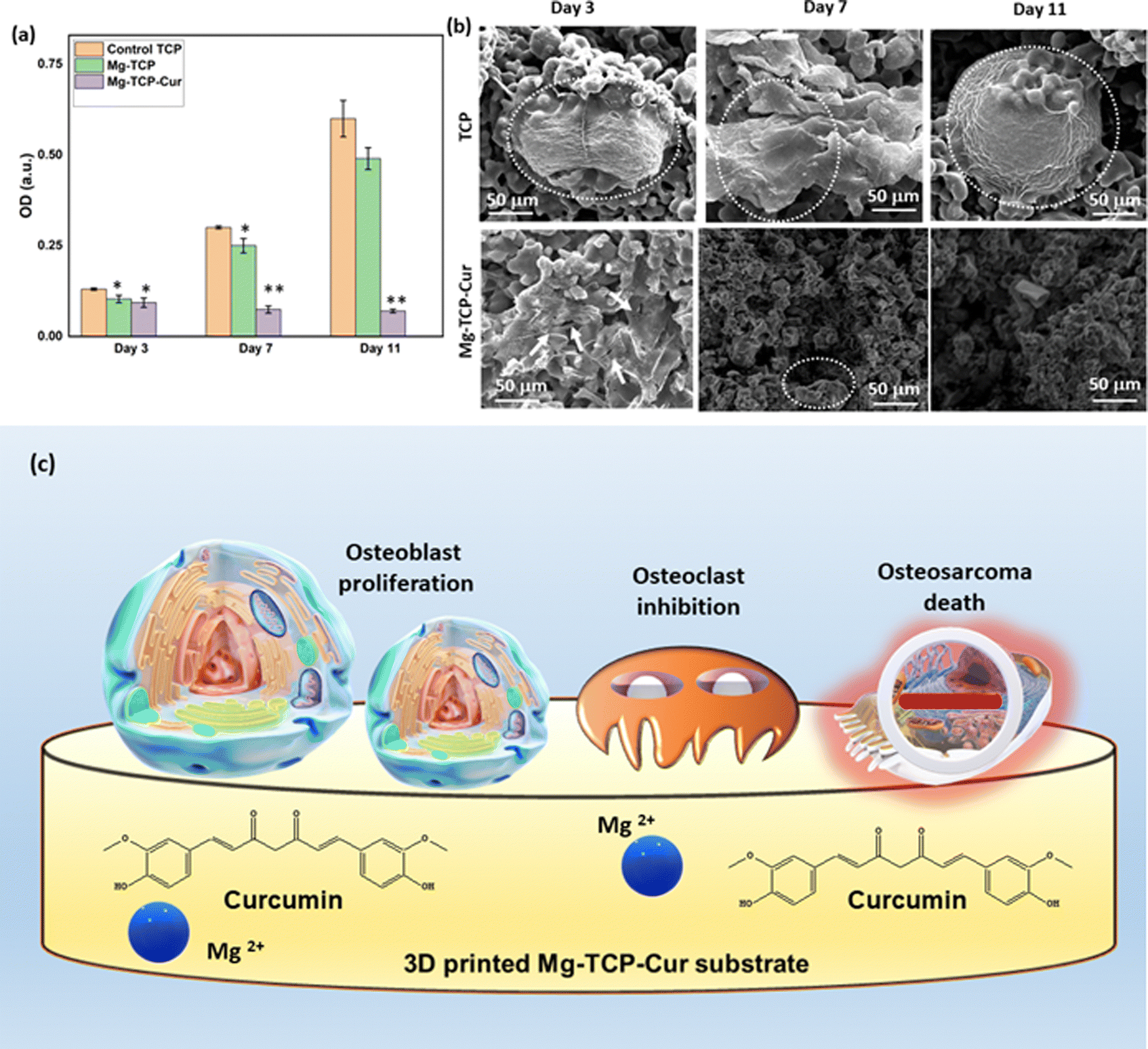 | ||
| Fig. 4 (a) MTT assay results after osteosarcoma cell-3D printed scaffolds interaction show that cell viability significantly reduces in presence of curcumin. The Mg-TCP-Cur composition shows ∼1.3 times reduced cell viability than the control on day 3. On day 7, this composition shows a cell viability reduction of ∼4 times, which further enhances to ∼8.5 times on day 11. The ** denotes a p value of <0.0001. (b) Healthy osteosarcoma cell attachment with filopodial extension is noticed in the FESEM image of control samples. In contrast, the curcumin-loaded composition show damaged filopodia (marked with arrows), or no significant cellular attachment to that of the control. The observed cells are identified with dotted arrows. (c) Schematic representing the osteoblast viability, osteoclast inhibition, and osteosarcoma inhibition on the 3D printed Mg-TCP-Cur scaffold surface. | ||
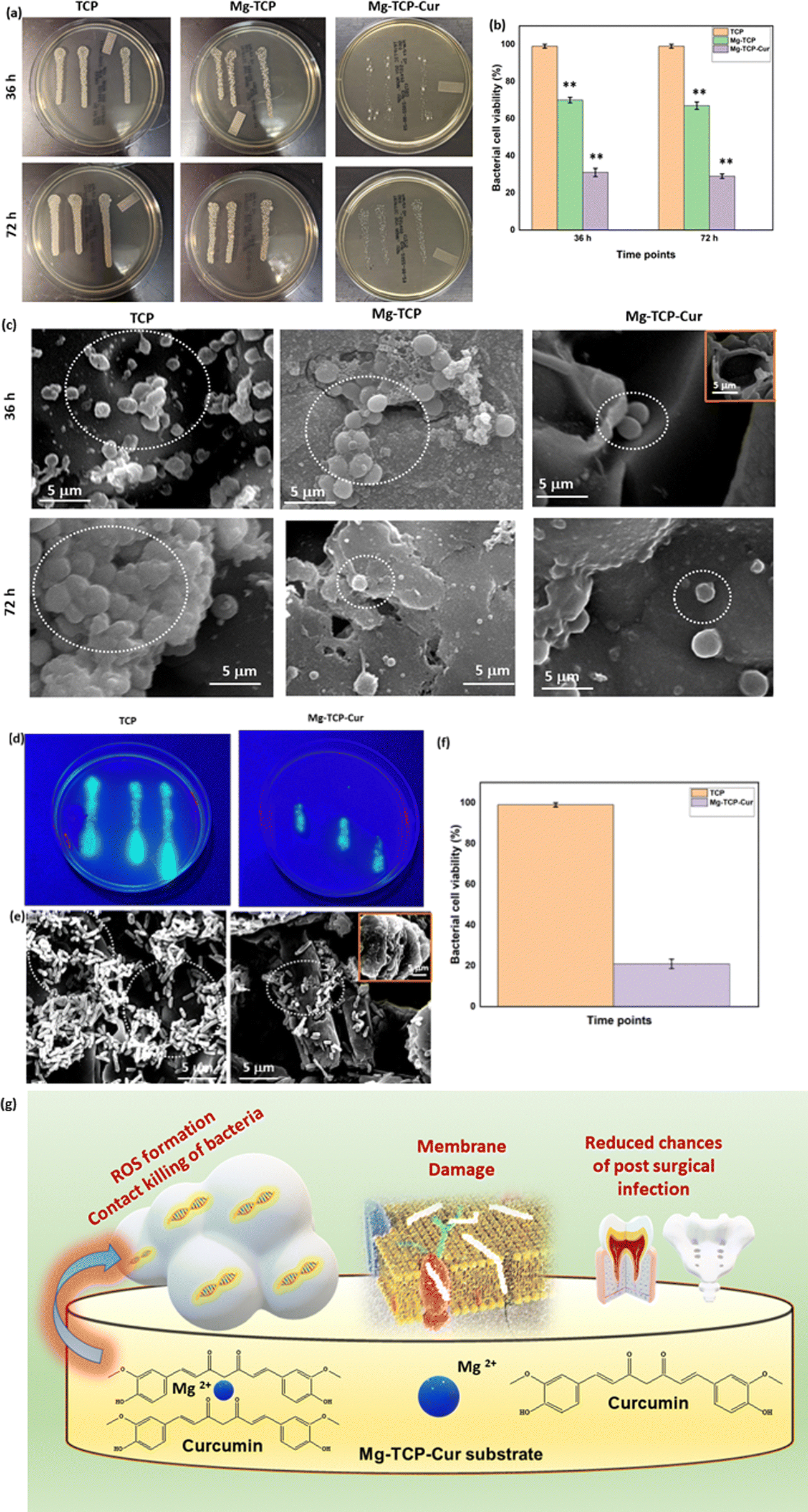 | ||
| Fig. 5 The antibacterial test results for 36 h and 72 h against S.aureus based on the modified ISO 22196:2011 Standard of agar plate counting method (a) The agar plate images indicate that Mg-TCP and Mg-TCP-Cur result in a significantly less number of bacterial colony formation than that of the control. (b) The bacterial cell viability quantification results indicate that Mg-TCP composition shows the highest ∼33% antibacterial efficiency and the Mg-TCP-Cur composition shows the highest ∼71% antibacterial efficiency than the control. The ** denotes a p value of <0.0001. (c) The FESEM results show a lesser number of bacterial densities in the treatment sample than that in the control. Inset FESEM image of the Mg-TCP-Cur composition shows bacterial cell debris, resulting due to puncture of bacterial cells in presence of Mg2+ and curcumin. (d) The antibacterial efficacy assessment against P. aeruginosa after 72 h of bacteria–scaffold interaction shows that Mg-TCP-Cur leads to a significant reduction in bacterial colonies. (e) The FESEM images show dense bacterial colonies in the control, whereas the Mg-TCP-Cur shows a smaller number of bacterial colonies with a clear dilation of bacterial cell walls. The inset image shows resultant debris due to the killing of bacteria. (f) The bacterial cell viability quantification results indicate that ∼79% antibacterial efficacy is shown by the Mg-TCP-Cur composition. (g) Schematic representing the antibacterial mechanism of Mg-TCP-Cur composition due to ROS generation and bacterial cell wall dilation in presence of polyphenolic curcumin and Mg2+. The interaction between curcumin and Mg2+ is shown in this figure. | ||
The schematic of In vivo rat distal femur model, H&E staining, and quantification of new bone formation is shown in Fig. 6. Design of the 3D printed scaffolds with 2.5 mm diameter and 4 mm height, a schematic of the implant location in a rat distal femur model, surgery, and implantation, schematic of sample harvesting and cross-section cuts, utilized for different staining and quantifications of new bone, blood vessel regeneration is shown in Fig. 6(a). The optical microscopic images of the H&E-stained cross sections are shown in Fig. 6(b). In these images, “I” denotes the area surrounding the scaffold, “NB” indicates new bone formation, “NU” denotes the nucleus, and “F” denotes fibrous tissue. The quantification results (Fig. 6(c)) indicate that the Mg-TCP sample leads to ∼1.5 times enhancement in new bone formation than that of the control, which further increases to ∼2.5 times for the Mg-TCP-Cur sample. Fig. 6(d) shows a representative image, obtained during the RGB analysis of the H&E optical images. The optical microscopic images of the vWF-stained cross sections are shown in Fig. 7(a)–(f). The Fig. 7(a) and (b) show low magnification and high magnification images of TCP, and the low magnification and high magnification images of Mg-TCP are shown in Fig. 7(c) and (d) respectively, whereas Fig. 7(e) and (f) show the low mag and high mag images of Mg-TCP-Cur respectively. The blood vessels are identified with a white free-flowing area in the low mag images (Fig. 7(a), (c) and (e)). Selected blood vessel areas are shown in the inset images. The blood vessels are marked with an arrow in the corresponding high mag images (Fig. 7(b), (d), and (f)). Fig. 7(g)–(l) shows optical microscopic images of the SRBS-stained cross sections. The low mag images of TCP, Mg-TCP, and Mg-TCP-Cur are shown in Fig. 7(g)–(i) and the corresponding high mag images are shown in Fig. 7(j), (k), and (l) respectively. In the high mag images, “NB” stands for new bone, and “OB” stands for osteoblast respectively. The quantification of blood vessel formation results is shown in Fig. 8(a). The Mg-TCP leads to ∼1.6 times higher blood vessel formation than the control TCP, and no significant increase in blood vessel formation is observed in presence of curcumin. The new bone formation quantification using SRBS staining is shown in Fig. 8(b). The Mg-TCP shows ∼1.4 times higher bone formation than the control, which further increases to ∼2.3 times for the Mg-TCP-Cur composition. The optical images of the obtained cross sections after Movat pentachrome staining of TCP and Mg-TCP are shown in Fig. 8(c) and (d) respectively. In these images, “NB” denotes the new bone formation, and the area surrounding the scaffolds is marked with “I”. The obtained images show that the presence of MgO leads to a significant enhancement in new bone formation than that of the control. Fig. 8(e) shows the schematic representation of new blood vessel generation and bone regeneration after the implantation of the 3D printed scaffolds with MgO and curcumin. The X-ray radiograph (Fig. 8(f)) after 6 weeks of implantation shows that the scaffolds remain intact within the distal femur and no presence of aseptic loosening or fracture is noticed because of surgery.
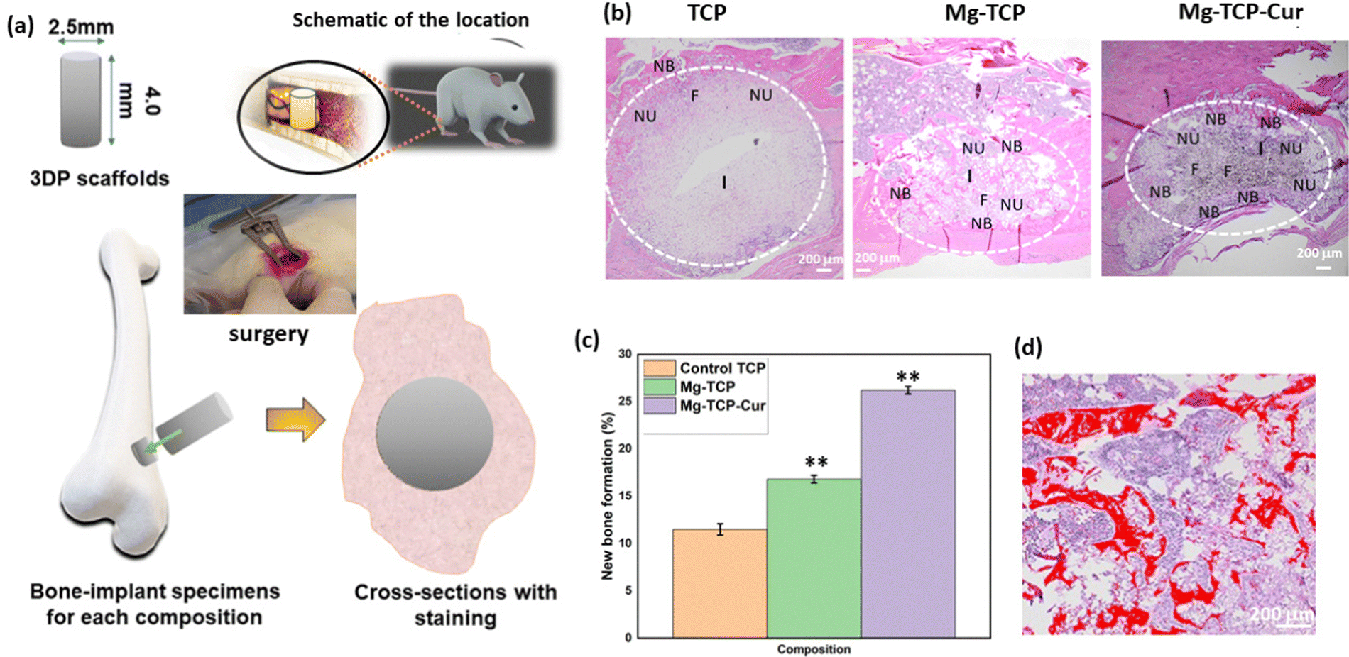 | ||
| Fig. 6 Schematic of In vivo rat distal femur model, H&E staining and quantification of new bone formation. (a) Design of the 3D printed scaffolds with 2.5 mm diameter and 4 mm height, a schematic of the implant location in a rat distal femur model, surgery and implantation; schematic of sample harvesting and cross-section cuts, utilized for different staining and quantifications of new bone, blood vessel formation. (b) Optical microscopic images of the H&E-stained cross sections. The implant area in each scaffold is marked with “I”, “NB” indicates new bone formation, “NU” denotes the nucleus, “F” indicates fibrous tissue. (c) Quantification of the new bone formation surrounding the scaffolds with RGB analysis show that the Mg-TCP sample leads to ∼1.5 times enhancement in new bone formation than that of the control, which further increases to ∼2.5 times for the Mg-TCP-Cur sample. (d) Representative image obtained during the quantification by RGB analysis. | ||
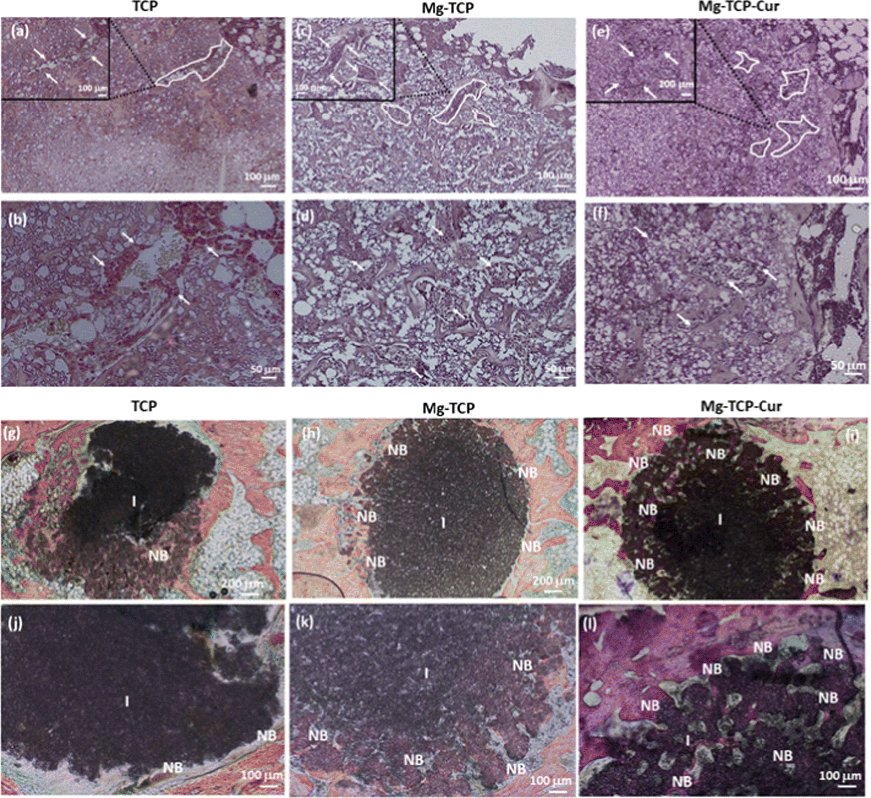 | ||
| Fig. 7 Optical microscopic images of the vWF-stained cross sections, (a) and (b) TCP sample in a low magnification and high magnification respectively, (c) and (d) Low mag and high mag images of Mg-TCP respectively. (e) and (f) Low mag and high mag images of Mg-TCP-Cur respectively. In the low mag images (a), (c), and (e), the blood vessels are identified with a free-flowing area, marked in white. Few specific blood vessels are shown in the corresponding inset images. In the high mag images (b), (d), and (f) the blood vessels are marked with an arrow. Optical microscopic images of the SRBS-stained cross sections are shown in Fig. (g)–(l). The low mag images of TCP, Mg-TCP, and Mg-TCP-Cur are shown in Fig. (g), (h), and (i) respectively. The corresponding high mag images are shown in (j), (k), and (l) respectively. In the high mag images, “NB” stands for new bone, and “OB” stands for osteoblast respectively. | ||
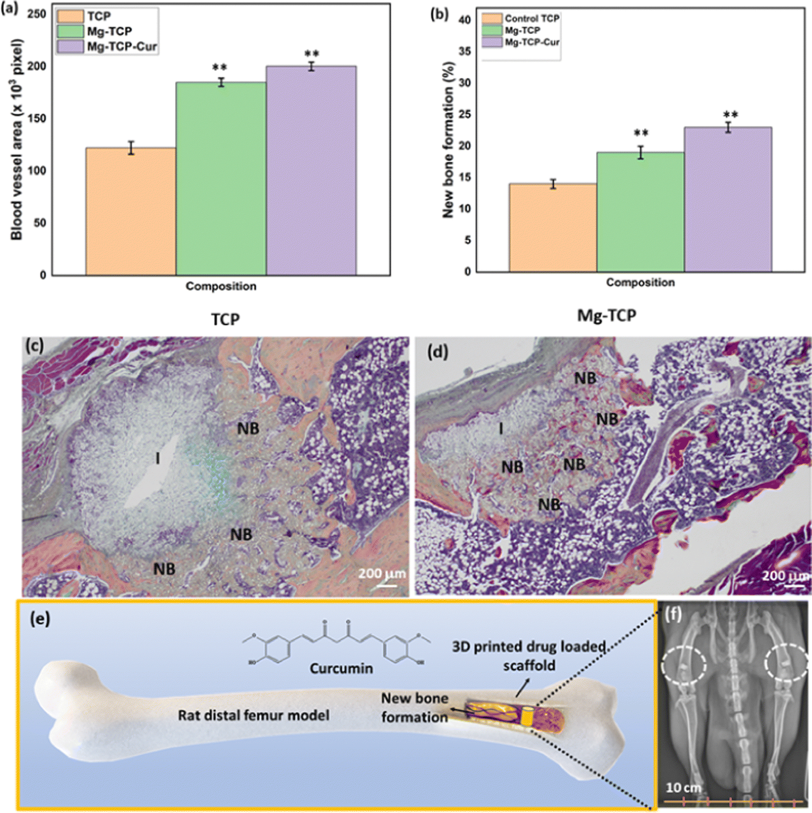 | ||
| Fig. 8 (a) Quantification of blood vessel formation results shows that the Mg-TCP leads to ∼1.6 times higher blood vessel formation than the control TCP. No significant decrease in blood vessel formation is observed in presence of curcumin. (b) The SRBS quantification results indicate that Mg-TCP shows ∼1.4 times higher bone formation than the control, which further increases to ∼2.3 times for the Mg-TCP-Cur composition. (c) and (d) Optical images of the obtained cross sections after Movat pentachrome staining of TCP and Mg-TCP respectively. The new bone formation is marked with “NB” and “I” denotes the area surrounding the 3Dprinted scaffold. The presence of Mg significantly enhances new bone formation than that of the control TCP. (e) Schematic showing the new blood vessel generation and bone formation after the implantation of the 3D printed scaffolds with curcumin. (f) The X-ray radiograph after 6 weeks of implantation shows that the scaffolds remain intact within the distal femur and no presence of aseptic loosening or fracture is noticed because of surgery. | ||
4. Discussions
Curcumin as an alternate chemopreventive natural molecule for bone tissue engineering
The early-stage osseointegration potential of curcumin makes it a suitable natural drug for various bone tissue engineering applications.43,54 Additionally, curcumin can be utilized as a safer alternative for chemoprevention due to its nontoxicity to healthy tissues and efficiency in preventing osteosarcoma.10 Curcumin, the active compound of turmeric is utilized as a spice in the Asian peninsula for centuries. Recent works suggest that curcumin influences several cell signaling pathways, associated with tumor and restrict the propagation of tumor cells by inhibiting the nuclear factor-κβ (NF-κβ) pathways.11 The NF-κβ is present in the cytoplasm of resting cells as a conjugate with Iκβ. This conjugate remains an inactive component. The activation of NF-κβ happens by the phosphorylation of Iκβ. In the next step, the activated NF-κβ transports to the nucleus and binds to the DNA, which triggers cancer cell proliferation. Curcumin hinders phosphorylation and restricts activation of the NF-κβ pathway.55,56 This mechanism further restricts the propagation of tumor cells. In our work, the cell viability assessment results (Fig. 4) indicate the potential of the fabricated drug delivery vehicle against osteosarcoma. Tumor site-specific drug delivery is challenging, and the effectiveness of the designed vehicle needs to be assessed to ensure the maximum benefit of a site-specific drug delivery system.23,57 Our approach is to design a site-specific drug delivery vehicle with curcumin loaded MgO-doped TCP that can serve a dual purpose of early-stage osseointegration and chemoprevention. Curcumin release from the MgO-doped TCP scaffolds depends on the following factors (a) surface degradation (b) diffusion (c) electrostatic interactions (d) complex formation ability between free Mg2+ and curcumin (e) hydrophobic and hydrophilic interactions between the drug and surrounding environment.36,58 The obtained results after 24 h drug release (Fig. 1(c) and (e)) show a good fit (R2 > 0.9) with Weibull distribution.10 The obtained parametric values (Table S1, ESI†) determine the nature of the fitting curve as per eqn (1). The FESEM images after drug release (Fig. 1(j)–(k)) indicate higher degradation of scaffolds at pH 5.0 as compared to pH 7.4 (Fig. (h) and (i)). This is one of the contributing factors toward the higher release of curcumin at pH 5.0 from the scaffold surfaces.Multifunctional scaffold design strategies by 3D printing
Our innovative strategy of direct curcumin incorporation in the 3D printed MgO doped TCP scaffolds has unique advantages in terms of multifunctionality for bone tissue engineering applications, such as (a) antibacterial properties (b) ability to enhance bone-forming osteoblasts (c) inhibition of bone-eating osteoclasts (d) early stage osseointegration after in vivo implantation (e) in vitro chemopreventive potential. 3D printed scaffolds have unique advantages such as patient specificity and defect specificity.59 However, often poor mechanical strength of ceramic-based 3D printed scaffolds restricts their application in vivo.60,61 Inferior mechanical properties lead to postsurgical implant failure because the scaffolds can’t withstand the pressure from the newly formed bone.60 Hence, it is important to develop a strategy that can ensure sufficient strength of the scaffolds. Our design strategy and utilization of MgO as a dopant result in enhanced compressive strength of the scaffolds as 11 MPa than the control TCP as 8 MPa. MgO has the grain boundary-strengthening ability during sintering.18,19 This mechanism results in improved compressive strength for the MgO-doped TCP scaffolds. The obtained compressive strength is similar to human cancellous bone (2–10 MPa).12Multi-drug resistance of Gram-negative and Gram-positive bacteria is a serious clinical problem.33–35 Osteomyelitis-causing Gram-positive S. aureus bacteria and Gram-negative P. aeruginosa bacteria are two major microorganisms that cause severe infection after implantation and may lead to scaffold failure.62,63 Our results (Fig. 5) show that MgO-doped TCP with curcumin has antibacterial potential against both bacteria. The polyphenolic groups present in curcumin have the potential of generating reactive oxygen species (ROS) in contact with the bacterial cell wall and lead to its death.10 The bacterial colony-forming ability of P. aeruginosa is monitored by the quorum sensing (QS) signaling mechanism. Curcumin downregulates the genes associated with the QS mechanism and inhibits P. aeruginosa.64 The exact mechanism by which MgO restricts bacterial growth is yet to be explored. However, the existing literature reports suggest that it shows antibacterial potential due to the contact of Mg2+ with the bacterial cell wall as well as the formation of reactive oxygen species (ROS).65,66 In summary, the dual effects of curcumin and Mg2+ trigger bacterial cell death (Fig. 5). Antibiotic-resistant bacteria are a serious concern for the medical community. In that regard, curcumin and MgO may be utilized as effective alternatives.
Our approach is to inhibit tumor cells without affecting the healthy bone-forming osteoblast cells. This is a crucial challenge for localized drug delivery.21,67 We have mitigated this challenge by the direct incorporation of curcumin on the Mg-TCP scaffolds. Curcumin or similar natural phytochemicals do not induce toxicity to healthy cells up to a certain dose and the permeable limit of curcumin consumption is between 2–12 g per day per human.10 The initial cytocompatibility results indicate that a higher amount of curcumin (1000 μg and 1500 μg) leads death of healthy osteoblast cells. In contrast, a very low amount of curcumin such as 100 μg does not cause any significant increase in osteoblast viability. Among the tested compositions, 400 μg of curcumin shows a significant increase in osteoblast viability. The osteosarcoma viability reduction is directly proportional to the increasing amount of curcumin. Both, 400 μg and 1000 μg of curcumin lead to a significant reduction in osteosarcoma viability. The combination of osteoblast and osteosarcoma viability results indicates that a composition of curcumin between 400 μg and 1000 μg is expected to give optimal results. Based on this initial study, 500 μg of curcumin is selected for further analysis. Detailed osteoblast study results show that a combination of curcumin and MgO enhances osteoblast viability up to ∼1.4 times (Fig. 2(a)). Previous works suggest that curcumin promotes the differentiation of mesenchymal stem cells and helps in bone growth.43 Curcumin enhances the Runx2 and osteocalcin mRNA expressions and promotes osteoblast viability.68 It also upregulates Heme Oxygenase 1 (HO-1) pathway and enhances osteoblast differentiation.69 Recent works suggest that divalent Mg2+ ions promote integrin-mediated mechanisms that help in osteoblast attachment and proliferation over the Mg2+-containing implant surface. Our MTT and FESEM results (Fig. 2) corroborate well with this hypothesis, suggesting enhanced osteoblast proliferation and growth over the Mg-TCP and Mg-TCP-Cur scaffold surfaces.
The potential of this drug delivery system for osteoclast reduction is shown in Fig. 3. TRAP enzyme is secreted by the osteoclast cells during bone resorption, and it is a marker to quantify osteoclastic activity.70 Our results show a significant decrease in TRAP expression in presence of Mg2+ and curcumin. This behavior is possible because of two reasons (a) there are fewer viable cells on the treatment samples (b) the cells are not attached well to the scaffold surface, and they are unable to resorb the TCP, followed by releasing TRAP. The live dead assay (Fig. 3(c)) supports the first hypothesis. In presence of MgO and curcumin, a significant number of dead cells (red dots) are seen as opposed to living cells (green dots) in control. The resorption pit analysis (Fig. 3(b)) supports the second hypothesis. The control sample shows a significantly higher pit formation due to the resorption of TCP by osteoclasts. In contrast, the treatment samples show significantly lesser pit area. This can be attributed to lesser osteoclastic activity and cellular attachment on the scaffold surface. Hence, the TRAP assay, live–dead staining, and resorption pit analysis together suggest the effectiveness of Mg2+ and curcumin in reducing osteoclastic bone resorption.
Enhanced in vivo performance of the designed drug delivery system
Assessment of the successful in vivo performance of Mg-based implants is a significant challenge.20,27,71 Previous studies show that Mg-based implants may trigger tissue emphysema and cause animal death after surgery.27,72 This can be attributed to (a) rapid degradation of the implant and (b) hydrogen release after degradation from the implant in vivo. In our work, we have mitigated these challenges by using MgO as a dopant with TCP. Survival of all the animals after surgery and no evidence of fracture or infection unequivocally establish the successful implantation of MgO-doped 3D printed TCP scaffolds. The X-ray radiograph in Fig. 8(f) supports this observation. Previous works report the Mg2+ ions are monitored by kidneys, and it rarely induces any severe side effects if present at a higher level.73 We have measured the amount of Ca2+ and Mg2+ in rat urine in one previous work with MgO–SrO dual-doped TCP.18 The reported results indicate that due to a lower amount of MgO doping, the released Mg2+ in rat urine is negligible. Whereas Ca2+ has shown a higher release, probably due to faster degradation of the scaffolds without MgO. In summary, the obtained results have shown that long-term (84 days) release of Ca2+ and Mg2+ from the scaffolds do not cause any adverse effect on animal health or scaffold quality.New bone formation in presence of MgO is visible in the H&E quantification images (Fig. 6(b)–(d)). The SRBS staining results (Fig. 7(g)–(l) and 8(b)) corroborate well with the H&E quantification results. New bone formation in presence of curcumin and MgO is further confirmed by the quantification after SRBS staining.44,45 The presence of MgO leads to ∼1.4 times higher bone formation, which further increases to ∼2.3 times in presence of curcumin with MgO (Fig. 8(b)). Enhanced early-stage new trabecular bone formation in presence of MgO and curcumin indicates the osteogenic potential of these drug delivery systems. This enhancement is due to the dual effects of osteoblast increase and osteoclast decrease by both MgO and curcumin. Previous studies report that the presence of curcumin on the implant surface reduces fibrous encapsulation and improves bone-implant contact.74 The presence of MgO dopant results in new blood vessel formation after implantation. The growth of new blood vessels results in nutrient supply to the newly grown bone segment.70 Our quantification results (Fig. 8) reveal that the presence of MgO helps to significantly enhance blood vessel formation as compared to the control. This result further strengthens the potential of utilizing MgO-doped TCP as a bone scaffold. However, the presence of curcumin with MgO-doped TCP does not show any significant improvement in blood vessel generation as compared to the MgO-doped TCP. Our work corroborates well with the available reports that curcumin does not cause a significant increase in blood vessel formation or angiogenesis.75 It can be concluded that the fabricated scaffolds have angiogenic potential due to the presence of MgO. The role of MgO in new bone formation is further analyzed with Movat Penta chrome staining (Fig. 8(c) and (d)).50–52 The obtained results show that the presence of MgO as a dopant leads to significantly enhanced bone formation as compared to the control TCP.
5. Conclusions
In summary, our work indicates that curcumin-loaded MgO-doped 3D printed TCP shows improved in vitro and in vivo performance. The presence of MgO and curcumin leads to increased osteoblast viability (up to 1.4 times), inhibition in osteoclast activity, and enhanced in vivo bone formation ability (up to 2.5 times) after 6 weeks of implantation in rat distal femur model. The presence of MgO significantly enhances blood vessel formation. These scaffolds show up to ∼71% antibacterial efficacy against S. aureus and ∼79% efficacy against P. aeruginosa. In vitro chemopreventive potential assessment results reveal that the presence of curcumin leads to a significant reduction (up to ∼8.5 times) of osteosarcoma viability compared to the control. These multifunctional curcumin-loaded 3D printed scaffolds can be utilized as a bone graft for patient-specific and defect-specific low load-bearing sites.Data availability
Data presented in this manuscript will be made available upon reasonable request to the corresponding author.Conflicts of interest
The authors do not have any possible conflict of interest. The content is solely the responsibility of the authors and does not necessarily represent the official views of the National Institute of Health.Acknowledgements
The authors would like to acknowledge financial support from the National Institute of Dental and Craniofacial Research (NIDCR) of the NIH grant number R01 DE029204-01 (PI: Bose). The authors would like to thank the Franceschi Microscopy & Imaging Center at WSU.References
- D. Ke and S. Bose, Addit. Manuf., 2018, 22, 111–117 CAS
.
- W. Wang and K. W. K. Yeung, Bioact. Mater., 2017, 2, 224–247 CrossRef PubMed
- S. Bose and S. Tarafder, Acta Biomater., 2012, 8, 1401–1421 CrossRef CAS PubMed
- F. Fagioli and E. Tirtei, Lancet Oncol., 2020, 21, 331–332 CrossRef PubMed
- S. Bose, N. Sarkar and D. Banerjee, Acta Biomater., 2021, 126, 63–91 CrossRef CAS PubMed
- C. Koski, N. Sarkar and S. Bose, J. Mater. Chem. B, 2020, 8, 2048–2062 RSC
- E. C. González Díaz, A. G. Lee, L. C. Sayles, C. Feria, E. A. Sweet-Cordero and F. Yang, Adv. Healthcare Mater., 2022, 11, 2200768 CrossRef PubMed
- Y. Zhang, D. Zhai, M. Xu, Q. Yao, J. Chang and C. Wu, J. Mater. Chem. B, 2016, 4, 2874–2886 RSC
- J. E. Noe, Integr. Cancer Ther., 2009, 8, 409–415 CrossRef CAS PubMed
- A. Bhattacharjee and S. Bose, J. Mater. Res., 2022, 37(12), 2009–2020 CrossRef CAS
- S. Banerjee, C. Ji, J. E. Mayfield, A. Goel, J. Xiao, J. E. Dixon and X. Guo, Proc. Natl. Acad. Sci. U. S. A., 2018, 115, 8155–8160 CrossRef CAS PubMed
- A. Bhattacharjee and S. Bose, Mater. Des., 2022, 221, 110903 CrossRef CAS
- E. Steijvers, A. Ghei and Z. Xia, Biomater. Transl., 2022, 3, 65 Search PubMed
- B. Feng, M. Zhang, C. Qin, D. Zhai, Y. Wang, Y. Zhou, J. Chang, Y. Zhu and C. Wu, Bioact. Mater., 2023, 22, 127–140 CrossRef CAS PubMed
- D. Jenkins, K. Salhadar, G. Ashby, A. Mishra, J. Cheshire, F. Beltran, M. Grunlan, S. Andrieux, C. Stubenrauch and E. Cosgriff-Hernandez, Bioact. Mater., 2022, 13, 1–8 CrossRef CAS PubMed
- S. Bose, S. Vahabzadeh and A. Bandyopadhyay, Mater. Today, 2013, 16, 496–504 CrossRef CAS
- F. Baino and M. Ferraris, Int. J. Appl. Ceram. Technol., 2017, 14, 507–520 CrossRef CAS
- S. Tarafder, N. M. Davies, A. Bandyopadhyay and S. Bose, Biomater. Sci., 2013, 1, 1250–1259 RSC
- W. Xue, K. Dahlquist, A. Banerjee, A. Bandyopadhyay and S. Bose, J. Mater. Sci.: Mater. Med., 2008, 19, 2669–2677 CrossRef CAS PubMed
- L. Xu, F. Pan, G. Yu, L. Yang, E. Zhang and K. Yang, Biomaterials, 2009, 30, 1512–1523 CrossRef CAS PubMed
- S. He, J. Fang, C. Zhong, M. Wang and F. Ren, Adv. Healthcare Mater., 2022, 2201096 CrossRef CAS PubMed
- Y. Zou, B. Huang, L. Cao, Y. Deng and J. Su, Adv. Mater., 2021, 33, 2005215 CrossRef CAS PubMed
- C. Garot, G. Bettega and C. Picart, Adv. Funct. Mater., 2021, 31, 2006967 CrossRef CAS PubMed
- M. Roy and S. Bose, J. Biomed. Mater. Res., Part A, 2012, 100, 2450–2461 Search PubMed
- M. Kansara, M. W. Teng, M. J. Smyth and D. M. Thomas, Nat. Rev. Cancer, 2014, 14, 722–735 CrossRef CAS PubMed
- R. Agarwal and A. J. García, Adv. Drug Delivery Rev., 2015, 94, 53–62 CrossRef CAS PubMed
- J. Xue, S. Singh, Y. Zhou, A. Perdomo-Pantoja, Y. Tian, N. Gupta, T. F. Witham, W. L. Grayson and T. P. Weihs, Biofabrication, 2022, 14, 34107 CrossRef PubMed
- H. J. Busscher, H. C. van der Mei, G. Subbiahdoss, P. C. Jutte, J. J. A. M. van den Dungen, S. A. J. Zaat, M. J. Schultz and D. W. Grainger, Sci. Transl. Med., 2012, 4, 153rv10 Search PubMed
- X. Cui, T. Murakami, Y. Tamura, K. Aoki, Y. Hoshino and Y. Miura, ACS Appl. Mater. Interfaces, 2018, 10, 23674–23681 CrossRef CAS PubMed
- D. Hu, H. Li, B. Wang, Z. Ye, W. Lei, F. Jia, Q. Jin, K.-F. Ren and J. Ji, ACS Nano, 2017, 11, 9330–9339 CrossRef CAS PubMed
- C. T. Johnson, J. A. Wroe, R. Agarwal, K. E. Martin, R. E. Guldberg, R. M. Donlan, L. F. Westblade and A. J. García, Proc. Natl. Acad. Sci. U. S. A., 2018, 115, E4960–E4969 CAS
- C. E. Vantucci, H. Ahn, T. Fulton, M. L. Schenker, P. Pradhan, L. B. Wood, R. E. Guldberg, K. Roy and N. J. Willett, Biomaterials, 2021, 264, 120405 CrossRef CAS PubMed
- K. D. Roberts, Y. Zhu, M. A. K. Azad, M.-L. Han, J. Wang, L. Wang, H. H. Yu, A. S. Horne, J.-A. Pinson, D. Rudd, N. H. Voelcker, N. A. Patil, J. Zhao, X. Jiang, J. Lu, K. Chen, O. Lomovskaya, S. J. Hecker, P. E. Thompson, R. L. Nation, M. N. Dudley, D. C. Griffith, T. Velkov and J. Li, Nat. Commun., 2022, 13, 1625 CrossRef CAS PubMed
- W. Fan, H. Han, Z. Lu, Y. Huang, Y. Zhang, Y. Chen, X. Zhang, J. Ji and K. Yao, Bioeng. Transl. Med., 2023, 8, e10380 CAS
- L. Zou, X. Li, Y. Huang, C. Wang, Y. Fang, J. Zhao, Q. Jin and J. Ji, Nano Today, 2023, 50, 101828 CrossRef CAS
- S. Tarafder and S. Bose, ACS Appl. Mater. Interfaces, 2014, 6, 9955–9965 CrossRef CAS PubMed
- S. Tarafder, V. K. Balla, N. M. Davies, A. Bandyopadhyay and S. Bose, J. Tissue Eng. Regener. Med., 2013, 7, 631–641 CrossRef CAS PubMed
- A. Bigi, E. Boanini, S. Panzavolta and N. Roveri, Biomacromolecules, 2000, 1, 752–756 CrossRef CAS PubMed
- S. Dash, P. N. Murthy, L. Nath and P. Chowdhury, Acta Pol. Pharm., 2010, 67, 217–223 CAS
- E. Boanini, P. Torricelli, M. Gazzano, R. Giardino and A. Bigi, Biomaterials, 2008, 29, 790–796 CrossRef CAS PubMed
- L. Wang, Y. Meng, Y. Feng, H. Wang, L. Mao, S. Yu and Z. Wang, Adv. Healthcare Mater., 2022, 2201248 CrossRef CAS PubMed
- L. Wang, M. Wang, M. Li, Z. Shen, Y. Wang, Y. Shao and Y. Zhu, CrystEngComm, 2018, 20, 5744–5753 RSC
- N. Sarkar and S. Bose, ACS Appl. Mater. Interfaces, 2020, 12, 13644–13656 CrossRef CAS PubMed
- S. K. Lan Levengood, S. J. Polak, M. B. Wheeler, A. J. Maki, S. G. Clark, R. D. Jamison and A. J. Wagoner Johnson, Biomaterials, 2010, 31, 3552–3563 CrossRef CAS PubMed
- A. M. Wojtowicz, A. Shekaran, M. E. Oest, K. M. Dupont, K. L. Templeman, D. W. Hutmacher, R. E. Guldberg and A. J. García, Biomaterials, 2010, 31, 2574–2582 CrossRef CAS PubMed
- X. Liu, L. Li, B. Gaihre, S. Park, Y. Li, A. Terzic, B. D. Elder and L. Lu, ACS Nano, 2022, 16, 2741–2755 CrossRef CAS PubMed
- M. F.-U. Rahman, Y. Yang, B. T. Le, A. Dutta, J. Posyniak, P. Faughnan, M. A. Sayem, N. S. Aguilera and G. Mohi, Nat. Commun., 2022, 13, 1–16 Search PubMed
- A. T. Bauer, E. A. Strozyk, C. Gorzelanny, C. Westerhausen, A. Desch, M. F. Schneider and S. W. Schneider, Biomaterials, 2011, 32, 8385–8393 CrossRef CAS PubMed
- L. Wang, S. Li, L. Zhong, Q. Li, S. Liu, W. Zheng and X. Jiang, J. Mater. Chem. B, 2021, 9, 3025–3031 RSC
- V. Alt, U. Thormann, S. Ray, D. Zahner, L. Dürselen, K. Lips, T. El Khassawna, C. Heiss, A. Riedrich, G. Schlewitz, A. Ignatius, M. Kampschulte, H. von Dewitz, S. Heinemann, R. Schnettler and A. Langheinrich, Acta Biomater., 2013, 9, 7035–7042 CrossRef CAS PubMed
- U. Thormann, S. Ray, U. Sommer, T. ElKhassawna, T. Rehling, M. Hundgeburth, A. Henß, M. Rohnke, J. Janek and K. S. Lips, Biomaterials, 2013, 34, 8589–8598 CrossRef CAS PubMed
- S. Fuchs, X. Jiang, H. Schmidt, E. Dohle, S. Ghanaati, C. Orth, A. Hofmann, A. Motta, C. Migliaresi and C. J. Kirkpatrick, Biomaterials, 2009, 30, 1329–1338 CrossRef CAS PubMed
- M. N. P. Vidal and J. M. Granjeiro, J. Biomed. Sci. Eng., 2017, 10, 431 CrossRef CAS
- B. Li, R. Huang, J. Ye, L. Liu, L. Qin, J. Zhou, Y. Zheng, S. Wu and Y. Han, Chem. Eng. J., 2021, 403, 126323 CrossRef CAS
- C. Mohanty and S. K. Sahoo, Biomaterials, 2010, 31, 6597–6611 CrossRef CAS PubMed
- M. H. Park and J. T. Hong, Cells, 2016, 5, 15 CrossRef PubMed
- X. Liu, N. Huang, H. Wang, H. Li, Q. Jin and J. Ji, Biomaterials, 2013, 34, 8370–8381 CrossRef CAS PubMed
- S. Prasad, D. DuBourdieu, A. Srivastava, P. Kumar and R. Lall, Int. J. Mol. Sci., 2021, 22, 7094 CrossRef CAS PubMed
- S. Bose, Y. Jo, U. Majumdar and A. Bandyopadhyay, Addit. Manuf. Biomed. Appl., 2022, 23A, 0 Search PubMed
- C. Bergmann, M. Lindner, W. Zhang, K. Koczur, A. Kirsten, R. Telle and H. Fischer, J. Eur. Ceram. Soc., 2010, 30, 2563–2567 CrossRef CAS
- W. Liu, Z. Huan, C. Wu, Z. Zhou and J. Chang, Composites, Part B, 2022, 247, 110324 CrossRef CAS
- S. An, J. Murtagh, K. B. Twomey, M. K. Gupta, T. P. O’Sullivan, R. Ingram, M. A. Valvano and J. Tang, Nat. Commun., 2019, 10, 1–11 CrossRef CAS PubMed
- A. R. Zelmer, R. Nelson, K. Richter and G. J. Atkins, Bone Res., 2022, 10, 53 CrossRef CAS PubMed
- T. Rudrappa and H. P. Bais, J. Agric. Food Chem., 2008, 56, 1955–1962 CrossRef CAS PubMed
- N.-Y. T. Nguyen, N. Grelling, C. L. Wetteland, R. Rosario and H. Liu, Sci. Rep., 2018, 8, 1–23 Search PubMed
- K. Demishtein, R. Reifen and M. Shemesh, Nutrients, 2019, 11, 2363 CrossRef CAS PubMed
- S. G. Antimisiaris, A. Marazioti, M. Kannavou, E. Natsaridis, F. Gkartziou, G. Kogkos and S. Mourtas, Adv. Drug Delivery Rev., 2021, 174, 53–86 CrossRef CAS PubMed
- Q. Gu, Y. Cai, C. Huang, Q. Shi and H. Yang, Pharmacogn. Mag., 2012, 8, 202 CrossRef CAS PubMed
- X. Yang, H. Jiang and Y. Shi, Cell Biosci., 2017, 7, 1–8 CrossRef PubMed
- S. Bose, D. Banerjee and A. A. Vu, ACS Appl. Mater. Interfaces, 2022, 14, 12964–12975 CrossRef CAS PubMed
- Z. Gu, S. Wang, W. Weng, X. Chen, L. Cao, J. Wei, J.-W. Shin and J. Su, Mater. Sci. Eng., C, 2017, 75, 620–628 CrossRef CAS PubMed
- D. Noviana, D. Paramitha, M. F. Ulum and H. Hermawan, J. Orthop. Transl., 2016, 5, 9–15 Search PubMed
- H. M. Wong, Y. Zhao, V. Tam, S. Wu, P. K. Chu, Y. Zheng, M. K. T. To, F. K. L. Leung, K. D. K. Luk and K. M. C. Cheung, Biomaterials, 2013, 34, 9863–9876 CrossRef CAS PubMed
- R. He, X. Hu, H. C. Tan, J. Feng, C. Steffi, K. Wang and W. Wang, J. Mater. Chem. B, 2015, 3, 2137–2146 RSC
- R. Daya, C. Xu, N.-Y. T. Nguyen and H. H. Liu, ACS Appl. Mater. Interfaces, 2022, 14, 11051–11067 CrossRef CAS PubMed
Footnote |
| † Electronic supplementary information (ESI) available: Fig. S1: XRD results of TCP indicate predominantly β – TCP (JCPDS # 09-0169) phases after sintering with some α – TCP (JCPDS # 09-0348) phases. The Mg-TCP sample shows only β – TCP phase; Fig. S2: Weibull fitting of obtained drug release data after 30 days of release (a) at pH 7.4 (b) at pH 5.0; Fig. S3: MTT assay results after interaction with different amounts of curcumin-loaded scaffolds and osteoblast on day 5 show that the Cur 3 sample shows a significant increase in cellular viability, which decreases for the compositions Cur 4 and Cur 5; Fig. S4: MTT assay results after interaction of osteosarcoma with different amounts of curcumin-loaded scaffolds show that the presence of curcumin leads to a significant reduction in osteosarcoma cell viability on day 5. See DOI: https://doi.org/10.1039/d2tb02547g |
| This journal is © The Royal Society of Chemistry 2023 |