
High-performance aqueous sodium-ion/sulfur battery using elemental sulfur†
Mukesh
Kumar
a,
Neha
Thakur
a,
Ankur
Bordoloi
 b,
Ashok
Kumar Yadav
c,
Shambhunath
N. Jha
c,
Dibyendu
Bhattacharyya
c,
Debaprasad
Mandal
a and
Tharamani C.
Nagaiah
*a
b,
Ashok
Kumar Yadav
c,
Shambhunath
N. Jha
c,
Dibyendu
Bhattacharyya
c,
Debaprasad
Mandal
a and
Tharamani C.
Nagaiah
*a
aDepartment of Chemistry, Indian Institute of Technology Ropar, Rupnagar, Punjab-140001, India. E-mail: tharamani@iitrpr.ac.in
bCouncil of Scientific and Industrial Research–Indian Institute of Petroleum (CSIR–IIP), Dehradun, India
cAtomic & Molecular Physics Division, Bhabha Atomic Research Centre, Mumbai – 400 094, India
First published on 26th April 2022
Abstract
Despite a promising outlook, the large-scale application of aqueous rechargeable sodium-ion batteries (ARSIBs) was impeded due to low-capacity electrode materials. Herein, we report a high capacity elemental sulfur-anode (S@NiVP/Pi-NCS) for aqueous rechargeable sodium ion/sulfur batteries using 70% of elemental sulfur, which delivers an outstanding capacity of 826 mA h g−1 at 0.5C with an excellent cycling stability even at 10C and a negligible capacity decay with 0.03% sulfur loss per cycle even after 400 cycles. The NiVP/Pi-NCS host combines the merits of fast anchoring and high conductivity of the composite to achieve smooth anchoring-diffusion and conversion of sodium polysulfide. The superior anchoring and accelerated polysulfides redox kinetics were confirmed by various electrochemical studies and in situ spectro-electrochemical analysis. Chemical interaction with vanadium provides faster redox kinetics of polysulfide conversion and efficient anchoring as revealed by XPS and was further supported by XANES and EXAFS studies wherein the distortion at the V site and overlapping electronic states in the NiVP/Pi catalyst were observed. Further, a full cell battery assembled using S@NiVP/Pi-NCS anode and Na0.44MnO2 cathode demonstrates an excellent initial capacity of 756 mA h g−1 based on S loading and 98.3 mA h g−1 based upon total electrode weight with 95% of capacity retention even after 600 cycles and a remarkable energy density of 84 W h kg−1 at 0.5C. Two full cells connected in series able to power LED demonstrate its practical application.
Introduction
The development of safe, cost-effective, and high energy density batteries is a grand challenge of the 21st century for large storage applications such as electric vehicles and other grid storage applications.1–4 Even though lithium-ion batteries (LiBs) are well established, they stumble upon several challenges, prominently moderate energy density (<400 W h kg−1), highly flammable non-aqueous electrolyte, and ubiquitous safety concerns associated with the dendritic growth of Li in highly inflammable ether-based electrolytes.5–7 Besides, lithium scarcity and non-uniform geographical distribution render it challenging to meet the immensely growing demand for energy in the near future.8 In recent years, environmentally generous aqueous rechargeable sodium-ion batteries (ARSIB) are able to draw significant research curiosity due to their low cost and high safety compared to organic counterparts and deemed them as promising and economical energy storage technology for the future.9 More importantly, aqueous electrolyte alluring toward lower viscosity and high conductivity allows ARSIB batteries to operate at high current density compared to the organic electrolyte.10,11 Besides safety, manufacturing costs can be reduced significantly due to the elimination of firm inert conditions and drying assembly lines.12 Despite the many benefits of the aqueous system, unfortunately, grid application of aqueous batteries is limited by unsatisfactory energy density arising due to a limited operating potential window of 1.23 V because of oxygen and hydrogen gas evolution (OER and HER) occurring due to water electrolysis.13,14Despite potential limitations, a significant amount of stable cathode materials, including a metal oxide,15–17 polyanion,18,19 and Prussian blue analogues,9,20–23 have been reported. However, the development of an anode material is challenged by its poor stability, competitive HER, and low capacity, leading to decreased energy density and poor cycling performance.24,25 Hence, the development of high capacity anode materials is of utmost importance. Sulfur is considered to be a promising electrode material with high theoretical capacity (1675 mA h g−1), high energy density (2600 W h kg−1), low cost, earth abundance, and environmentally benign features.26 The inclusion of both earth-abundant materials such as sulfur and sodium ions along with environmentally benign aqueous electrolyte would be a game-changing strategy. Thus, it leads to safe, cost-effective, and high-rate performance cell chemistry without Li-metal and flammable electrolyte, and makes the aqueous rechargeable Na-ion/sulfur battery a prudent choice for next-generation energy storage. However, the most critical challenge in the aqueous sulfur battery is polysulfide dissolution during the discharge process, similar to the organic system.27 However, in aqueous electrolyte, the polysulfides react with water to form HS− and H2S gas, leading to a loss of active sulfur and capacity decay upon battery cycling.28
Although non-aqueous sulfur batteries are progressively getting significant attention since the last one decade, only three reports on elemental sulfur anode materials such as S@PPy,29 MWCNTs@S@PPy, and sulfur-Ketjen black have been reported in the recent past with aqueous electrolytes.28,30 More importantly, for the aqueous Na-ion/S battery, there are only two reports available where dissolved polysulfide was used as an anode in ARSIBs.31,32 The key catalyst requirement for sulfur batteries is that the catalyst should anchor the polysulfide and enable accelerated polysulfide redox kinetics. Transition metal phosphide/phosphate have been extensively used in various electrocatalytic applications due to their high conductivity compared to other polar transition metal oxides and sulfides, and are expected to accelerate polysulfide kinetics by strong chemical interaction. Herein, we have explored the combination of nickel vanadium phosphide/phosphate (NiVP/Pi) and nitrogen-containing carbon spheres (NCS) with 70% elemental sulfur (S@NiVP/Pi-NCS) as the anode for ARSIBs. The main prospect of the present study was to develop a highly conductive anode that confines the polysulfide within the electrode to inhibit H2S formation and accelerate the polysulfide redox kinetics (Scheme 1). The proposed S@NiVP/Pi-NCS was reported to be the first entrant as an anode for ARSIBs, demonstrating an unprecedented capacity of 826 mA h g−1 at 0.5C with an excellent cycling performance over 400 cycles at a very high C-rate of 10C, which discloses very low capacity fading of 0.03% per cycle. A full cell battery with the Na0.44MnO2 cathode demonstrates an initial capacity of 756 mA h g−1 with respect to (w.r.t) sulfur loading and 98.3 mA h g−1, depending on the total electrode weight at 0.5C with a very high capacity retention of 95% even after 600 cycles. Practical application was further shown by lightening a LED powered by two charged full cells connected in series.
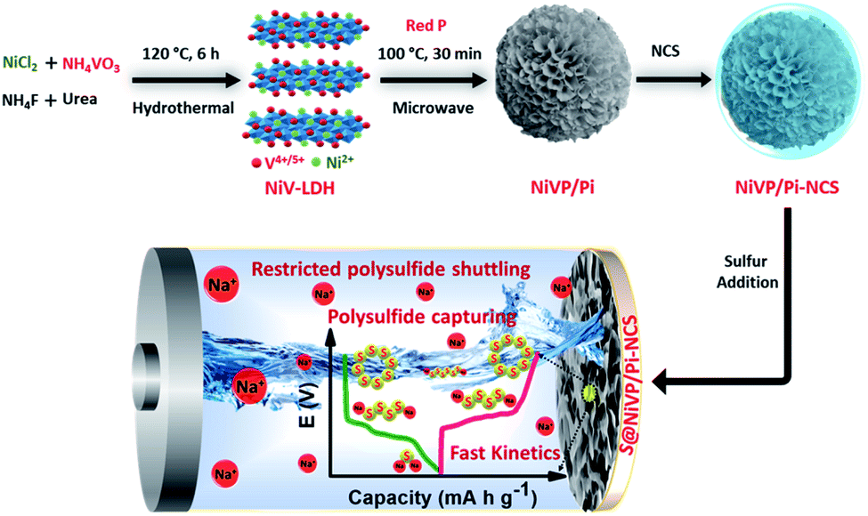 | ||
| Scheme 1 Schematic representation of the synthetic protocol of NiVP/Pi-NCS and redox conversion of polysulfide at S@NiVP/Pi-NCS anode in aqueous Na-ion/S battery. | ||
Experimental section
Synthesis of nitrogen-doped carbon sphere (NCS)
The NCS was synthesized using a soft templating approach following our already reported procedure.33 In a typical synthetic process, initially, 0.8 g of the template, i.e., Triton X-100, was dissolved in 50 mL of H2SO4 (8 wt%). After complete dissolution, distilled pyrrole was added to this solution under constant stirring. The resultant solution was kept in an ice bath for 20 min. Afterward, 2 mL of H2O2 (30%) was added dropwise under vigorous stirring in an ice bath and further stirred for 20 min before aging for 24 h at room temperature. The obtained product was filtered, thoroughly washed, and dried in an oven at 60 °C overnight, followed by heat treatment under an inert atmosphere at 800 °C to obtain a nitrogen-doped carbon sphere (NCS).Synthesis of NiVP/Pi
Desired catalyst synthesis involves two steps. In the first step, the precursor was prepared for NiVP/Pi synthesis by dissolving 20 mM NiCl2.6H2O (166.2 mg, 0.70 mmol) and 10 mM NH4VO3 (41 mg, 0.35 mmol) in 35 mL of deionized water under constant magnetic stirring. After 30 minutes of stirring, 0.18 M urea (378 mg, 6.30 mmol) and 0.18 M ammonium fluoride (233 mg, 6.30 mmol) were quickly added, and the reaction mixture was further stirred for another 30 minutes. Afterward, the resultant solution was transferred into a 50 mL of Teflon-lined autoclave and heated at 120 °C for 6 h. The resulting brown colored precursor sample of NiV(OH)2 was washed multiple times with water and ethanol, and kept for drying overnight at 60 °C. The second step involves microwave-assisted low-temperature phosphidation reactions of nickel vanadium layer double hydroxides (300 mg) with 100 mg of red phosphorous, which were carried out in a Multiwire Pro instrument from Anton Paar. The resultant mixture was dissolved in 10 mL water and transferred into Teflon-lined microwave vials. Before irradiation, the reaction mixture was deaerated with inert N2 to remove dissolved oxygen. The sample was irradiated with a microwave oven by controlled temperature programming by heating to 100 °C with a 15 min ramp and holding it for 30 min at 100 °C under a limiting pressure of 18 bar at 600 watts. The obtained precipitate was filtered and washed 2–3 times with DI water, then dried at 60 °C in an oven and designated as NiVP/Pi.Synthesis of NiVP/Pi-NCS
In a typical synthetic procedure, 50![[thin space (1/6-em)]](https://www.rsc.org/images/entities/char_2009.gif) :50 wt% of the as-synthesized NiVP/Pi and NCS were hand-ground for one hour to obtained the NiVP/Pi-NCS composite.
:50 wt% of the as-synthesized NiVP/Pi and NCS were hand-ground for one hour to obtained the NiVP/Pi-NCS composite.
Synthesis of Na0.44MnO2
Na0.44MnO2 synthesis involves a high-temperature solid-state reaction, following the previously reported literature.34 In a typical synthetic procedure, 1:0.484 molar ratio of pure Mn2O3 and Na2CO3 were hand-grinded by a mortar and pestle for an hour and calcinated at 500 °C for 5 h in the presence of air. After cooling, the obtained mixture was again grinded and further calcined at 900 °C for another 12 h in air and cooled at room temperature.
Preparation of S@NCS and S@NiVP/Pi-NCS
To obtain S@NCS and S@NiVP/Pi-NCS anode, 70 wt% sulfur was incorporated into the NCS and NiVP/Pi-NCS catalyst by physically grinding the desired catalyst for one hour, followed by the melt diffusion method by heating the obtained mixture at 155 °C for 12 h in a dry air oven and the obtained anode material was designated as S@NCS and S@NiVP/Pi-NCS, respectively.Electrochemical measurements
To investigate the electrochemical activity of the synthesized catalyst, the electrochemical measurements were initially performed in a three-electrode assembly sealed in a single compartment cell, where graphite electrode (Ø 5 mm) hosting a drop-coated anode acts as the working electrode, stainless steel was used as the counter electrode, and Ag/AgCl/3 M KCl acts as the reference electrode. Before each electrochemical study, the graphite electrode surface was cleaned with different grits of emery paper and washed thoroughly under a running tap, followed by deionized water. Further, any physically absorbed impure particles on the electrode surface were removed by sonication for 5 minutes in 1:1 (IPA:water) mixture. The electrodes (anode) was prepared by mixing 25:70:5 wt% of catalyst (NCS, NiVP/Pi-NCS), elemental sulfur, and PVDF, respectively. The catalyst slurry was prepared by homogeneously grinding the obtained mixture using a mortar and pestle and dispersing in an appropriate amount of N-methyl-2-pyrrolidone (NMP). The obtained slurry was drop-coated on a graphite electrode with an average loading of 2.038 mg cm−2 (1.426 mg cm−2 with respect to sulfur) and dried at 80 °C in a dry air oven.
All the electrochemical measurements were performed using a Biologic (VSP 300) potentiostat/galvanostat with FRA7M module, which was controlled by an EC-Lab V11.12 software. The electrochemical performance of all the respective anodes were evaluated in aqueous 2 M Na2SO4 electrolyte in the potential range between 0.4 V and −1.0 V vs. Ag/AgCl/3 M KCl by various electrochemical techniques, viz., cyclic voltammetry (CV) and galvanostatic charge–discharge measurements at various C rates. The electrochemical impedance spectroscopy (EIS) measurement was performed in a frequency range of 5 MHz to 10 μHz at −0.6 V vs. Ag/AgCl/3 M KCl. For full cell studies, a battery was assembled in the Swagelok T-cell system using the Na0.44MnO2 cathode, S@NiVP/Pi-NCS, or S@NCS anode in 2 M Na2SO4 as the electrolyte using N-117 membrane as the separator, with the average loading of the cathode to the anode fixed at 4.14:1. All the battery experiments were performed using a battery cycler (BCS-810, Biologic) in the potential range from 0.0 to 1.5 V. From the application point of view, a practical demonstration was carried to lighten the LED by connecting two fully charged batteries in series assembled using the Na0.44MnO2 cathode and the S@NiVP/Pi-NCS anode in 2 M Na2SO4 electrolyte.
Results and discussion
The NiVP/Pi microsphere synthesis involves a facile two-step approach, with initially the hydrothermal treatment of nickel chloride and ammonium metavanadate salts with urea to form nickel vanadium layered double hydroxide (NiV-LDH), followed by low-temperature (100 °C) microwave-assisted phosphidation with red phosphorous. The nitrogen-containing carbon spheres (NCS) were synthesized by employing a soft templating approach using Triton X-100, following the reported procedure.33 The proposed anode S@NiVP/Pi-NCS was prepared by physically grinding 1:1 ratio of NiVP/Pi and NCS, followed by sulfur incorporation by melt diffusion at 155 °C for 12 h and was further mixed with PVDF binder to give 25:70:5 wt% of NiVP/Pi-NCS, sulfur, and PVDF, respectively. Similarly, the S@NCS anode was synthesized with the same sulfur content for control experiments.
The estimation by thermogravimetric analysis (TGA) confirms 68% of sulfur in the developed anode S@NiVP/Pi-NCS, indicating the successful incorporation of sulfur (Fig. S1, ESI†). The synthesized NiVP/Pi by scanning electron microscopy (SEM, Fig. 1a) reveals the microsphere morphology resulting from several ultrathin nanosheets organized almost vertical to the surface that are crosslinked together, resulting in a multilayer 3D network structure of spheres. These finding were further supported by transmission electron microscopy (TEM) and high-resolution TEM (HR-TEM) techniques (Fig. 1b and c). Further, the scanning TEM (STEM) image and corresponding element dot mapping discloses the homogeneous distribution and coexistence of Ni, V, O, and P within the spheres (Fig. 1d–h). The selected area electron diffraction (SAED) pattern in Fig. S2 (ESI†) shows lower crystallinity due to the nanosheet structure. The powder X-ray diffraction (PXRD) pattern (Fig. S3, ESI†) resembled with reported NiV-LDH. More importantly, after phosphidation, an additional peaks due to NiPO4 and NiP appeared along with NiV-LDH, signifying the successful formation of nickel vanadium phosphide/phosphate designated as NiVP/Pi.35,36 The XRD pattern of NCS illustrates an amorphous nature with two broad peaks, one at 26° corresponding to the (002) plane and the other at 43° for the (100) plane, signifying the presence of the sp2 carbon network.33 On the other hand, after mixing with NCS (NiVP/Pi-NCS), the disappearance of the peaks corresponds to NiVP/Pi and a slight shift in the graphitic carbon (24.8°) was observed, signifying the casting of NCS over NiVP/Pi, which was further supported by the SEM images (Fig. S4, ESI†). More importantly, after the incorporation of sulfur, sharp, intense, multiple peaks indexed to orthorhombic sulfur was observed with lower intensity in S@NiVP/Pi-NCS compared to pristine sulfur, signifying the successful incorporation of sulfur (Fig. S5, ESI†).37
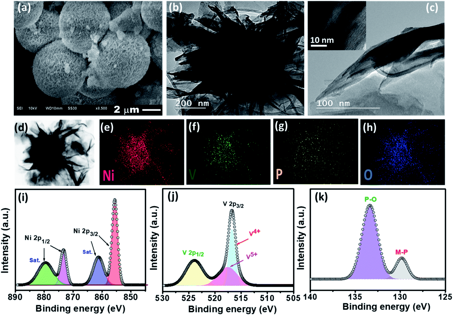 | ||
| Fig. 1 (a) SEM, (b) TEM, and (c) HR-TEM images of NiVP/Pi, (d) STEM image of NiVP/Pi and the corresponding EDS elemental dot mapping images of (e) nickel, (f) vanadium, (g) phosphorous, and (h) oxygen; deconvoluted XPS spectra of (i) Ni 2p, (j) V 2p, and (k) P 2p of NiVP/Pi. | ||
The oxidation state of NiVP/Pi was analyzed by X-ray photoelectron spectroscopy (XPS). The XPS survey spectrum confirms the presence of Ni, V, P, and O elements, and no impurities were present (Fig. S6, ESI†). As shown in Fig. 1i, the deconvoluted Ni 2p XPS spectrum of the as-prepared NiVP/Pi exhibits two peaks corresponding to Ni 2p1/2 and Ni 2p3/2 at a binding energy (BE) of 873.3 eV and 855.5 eV, respectively, which are separated by 17.6 eV along with satellite peaks at 879.4 eV and 861.1 eV, which is attributed to Ni2+. Similarly, the deconvoluted V 2p XPS spectrum (Fig. 1j) reveals V 2p1/2 and V 2p3/2 due to spin–orbit coupling and the peak of V 2p3/2 can be fitted into two constituent peaks corresponding to V4+ (516.7 eV) and V5+ (517.5 eV).35 The P 2p XPS spectrum shows two peaks; the one at higher binding energy (133.4 eV) corresponds to phosphate species, while the low intense peak at 129.8 eV is attributed to the metal phosphide (Fig. 1k). The O 1s XPS spectrum shows two peaks located at 530.7 eV and 531.7 eV, which can be assigned to O2− and OH−, respectively (Fig. S6b, ESI†). For S@NiVP/Pi-NCS, both Ni 2p and V 2p XP spectra show an increase in the binding energy, demonstrating the possible interaction of sulfur and NiVP/Pi-NCS host (Fig. S7 and S8, ESI†). Therefore, these strong interactions are anticipated to achieve a strong interfacial interaction to anchor the sodium polysulfide and increase the cycling stability. The XPS studies of S@NCS show the interaction of carbon with sulfur (Fig. S9, ESI†).
Besides, the electronic structure and electronic environment of the NiVP/Pi catalyst were studied using X-ray absorption near edge structure (XANES) and extended X-ray absorption fine structure (EXAFS) techniques. The normalized XANES spectrum of NiVP/Pi at the Ni K-edge is shown in Fig. 2a along with the standards Ni foil and NiO. The absorption edge position in the XANES spectrum corresponds to the oxidation state of the absorbing atom and it shifts toward higher energy with increasing oxidation state. The absorption edge position of NiVP/Pi clearly coincides with NiO, indicating the +2 oxidation state of Ni-ions; however, the EXAFS oscillations (Fig. 2b) clearly indicate different structures compared to NiO. The pre-edge peak can also be seen in NiVP/Pi with relatively less amplitude compared to NiO, which originates from the transition of 1s electron into higher level empty d states in transition metals due to hybridization. The normalized XANES spectrum of NiVP/Pi at the V K-edge is shown in Fig. 2c along with the V foil standard and V2O5, VOPO4, and VO2 references. As observed from Fig. 2c, the absorption edge of NiVP/Pi is located between VOPO4, V2O5, and VO2, indicating a mixed oxidation state of +5 and +4, which are consistent with the XPS results (Fig. 1j). More importantly, a relatively high intense pre-edge peak (5469 eV) in the V K-edge XANES is obtained from 1s to 3d transition, suggesting a strong hybridization and a higher degree of distortion at the V sites due to Ni incorporation in NiVP/Pi.
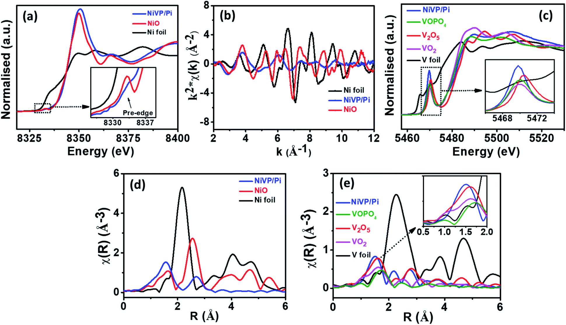 | ||
| Fig. 2 (a) Normalized XANES spectra of NiVP/Pi along with standard samples at the Ni K-edge, (b) EXAFS oscillation of NiVP/Pi along with standard samples in k-space at the Ni K-edge, (c) XANES spectra of NiVP/Pi and Fourier transform EXAFS spectrum at (d) Ni K-edge and (e) V K-edge of NiVP/Pi along with the standards. | ||
The Fourier-transform (FT) EXAFS spectrum at the Ni K-edge and V K-edge were also recorded to investigate the structure of NiVP/Pi at the atomic level. The spectrum in Fig. 2d exhibited two projecting coordination peaks at 1.56 Å and 2.7 Å that are ascribed to the Ni–O peak and Ni–Ni/V peak, respectively.38,39 The FT-EXAFS spectrum of NiVP/Pi at the V K-edge in Fig. 2e shows the first peak at 1.52 Å of the V–O bond, which is a slightly lower bond distance compared to the standard samples V2O5, VOPO4, and VO2. Two peaks between 2.0 and 3.5 Å is the contribution of V–Ni and V–V coordination at 2.56 Å and 3.36 Å, respectively.
The electrochemical performance of the proposed S@NiVP/Pi-NCS anode was initially evaluated by cyclic voltammetry (CV) measurements in Ar-saturated 2 M aqueous Na2SO4 electrolyte over the potential range from 0.4 V to −1.0 V at a scan rate of 2 mV s−1 in a three-electrode assembly using stainless steel (SS 316) and Ag/AgCl/3M KCl as the counter and reference electrode, respectively. The obtained CV (Fig. 3a) shows a well-defined redox behavior, exhibiting two clear cathodic and anodic peaks corresponding to the sulfur reduction–oxidation reaction. The initial reduction peak ca. −0.64 V is attributed to the sodiation of S8 to higher-order polysulfide, followed by a second reduction peak ca. −0.76 V ascribed to the subsequent reduction of a higher polysulfide to the final discharge product Na2S2/Na2S or HS−1. On the other hand, the oxidation peaks ca. −0.3 V and a feeble peak at ca. −0.1 V was observed, which can be attributed to the conversion of HS−1/Na2S to Na2S4 and Na2S4 to S8, signifying the reversibility of the process.40 Interestingly, S@NiVP/Pi-NCS shows high reversibility without any significant changes either in the peak potential or the peak current even after 50 cycles, validating faster redox kinetics and efficient polysulfide anchoring (Fig. 3b and S10, ESI†). In order to understand the anchoring ability and the polysulfide conversion of the proposed anode, control experiments were performed using S@NCS, which exhibits a broad reduction peak ca. −0.79 V and a broad oxidation peak ca. −0.23 V. The comparative CV of S@NiVP/Pi-NCS and S@NCS reveals that both the oxidation and reduction peak current are approximately two times higher for S@NiVP/Pi-NCS signifies the role of NiVP/Pi toward an enhanced redox kinetics of the polysulfide conversion (Fig. 3c and S11a, ESI†). The lower potential gap between the oxidation and reduction of sulfur for S@NiVP/Pi-NCS than S@NCS, signifying that the electrochemical reaction occurs faster with lower polarization. These results signify the enhanced catalytic activity of NiVP/Pi to lower the activation barrier (detailed in later section).
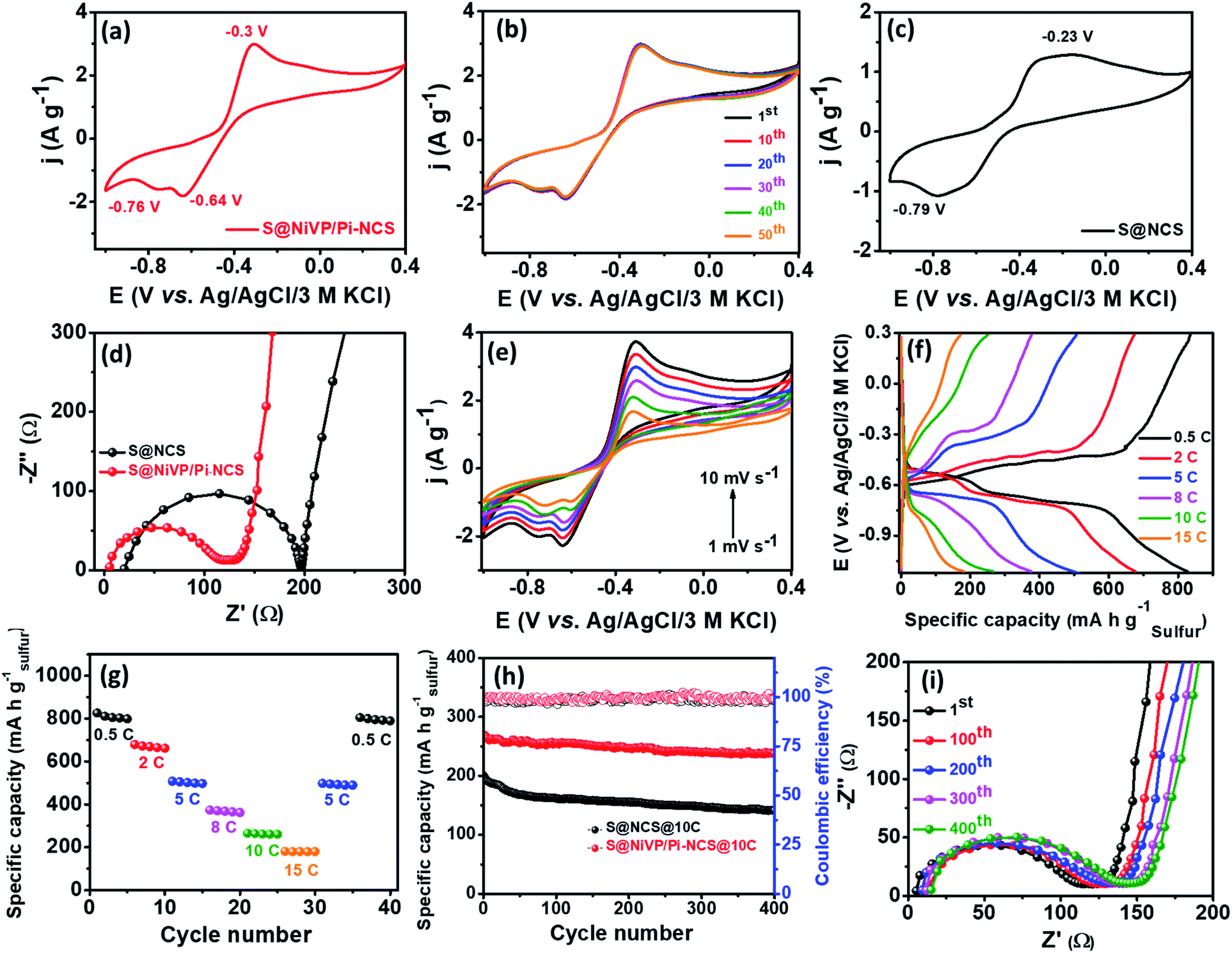 | ||
| Fig. 3 (a) CV and (b) cyclic stability of S@NiVP/Pi-NCS for 50 cycles at 2 mV s−1; (c) CV of S@NCS anode at 2 mV s−1; (d) EIS spectra of the respective anodes; (e) CVs at various scan rates; (f) voltage profile of S@NiVP/Pi-NCS; (g) rate performance of S@NiVP/Pi-NCS anode at different C-rates; (h) long term cycling performance of various anodes at 10C over 400 cycles in 2 M aq. Na2SO4 and (i) the corresponding EIS during cycling performance. | ||
The accelerated redox kinetics by S@NiVP/Pi-NCS was further elucidated by electrochemical impedance spectroscopic (EIS) measurements. The EIS spectra depicted in Fig. 3d reveals lower solution (Rs) and charge transfer resistance (Rct) for S@NiVP/Pi-NCS than S@NCS, which reinforces the fact that S@NiVP/Pi-NCS exhibit faster kinetics at the electrode–electrolyte interface. Moreover, the higher angle of the Warburg region for S@NiVP/Pi-NCS signifies that the process is not completely under diffusion control but has some capacitive nature due to the larger surface area and conductive nature of NCS.28 Further, to ascertain the kinetics of electron transfer at the electrode–electrolyte interface, the exchange current density and rate constant were calculated from EIS spectra using the following equations.41,42
| Rct = RT/nFi0 | (1) |
| Rct = RT/n2F2Ack0 | (2) |
Further, the CVs at different scan rates for S@NiVP/Pi-NCS (Fig. 3e) show negligible changes in the peak potential with increase in the scan rate, demonstrating the faster kinetics and high reversibility. The shapes of CVs are well maintained even at higher scan rates, demonstrating the superior activity of the NiVP/Pi-NCS catalyst to catalyze the polysulfide redox kinetics even at an elevated scan rates. The plot of anodic and cathodic peak current density vs. square root of different scan rates reveals the linear response, suggesting that the process is under diffusion control. Further, the ratio of anodic to cathodic current density against the scan rate remains close to unity, demonstrating the reaction is highly reversible even at higher scan rates (Fig. S17, ESI†). In contrast, for S@NCS without NiVP/Pi, the Ipa/Ipc ratio was found to be 1.18, which signifies that the sluggish cathodic conversion of polysulfide is the rate-determining step.
To comprehend the proposed anode for battery applications, galvanostatic charge–discharge experiments were performed using a similar three-electrode system. The charge–discharge profile at 0.5C in Fig. 3f displays two clear discharge plateaus at ca. −0.62 V and −0.75 V, respectively. The voltage plateau at ca. −0.62 V is ascribed to the reduction of elemental sulfur (S8) to higher-order polysulfide (Na2Sx, 4 < x < 8). Further, for the sweeping potential to the more cathodic region, the second plateau at ca. −0.75 V was appeared due to the reduction of higher-order polysulfide to lower-order polysulfide (Na2Sx, 4 > n) and finally to Na2S/HS−1. As depicted in Fig. 3f and g, S@NiVP/Pi-NCS shows an excellent performance with a very high specific capacity of 826 mA h g−1 at 0.5C [based on S loading, which is 77% of the theoretical S capacity (1072 mA h g−1) detailed in the ESI†] with an average loading of 1.426 mg cm−2 based on the sulfur weight. On the other hand, S@NCS shows 626 mA h g−1 of capacity at 0.5C under similar conditions (Fig. S18 and S19A, ESI†). The obtained capacity is very high compared to the previously reported literature for ARSIBs (Table S6, ESI†).
Notably, NiVP/Pi and NiVP/Pi-NCS contributed only 30 mA h g−1 and 45 mA h g−1 due to pseudocapacitive Na+ storage, which demonstrates that sulfur contributes toward the maximum capacity (Fig. S20 and S21, ESI†).
To understand the synergy between the anchoring strength toward polysulfide and its catalytic conversion by S@NiVP/Pi-NCS, charge–discharge experiments were performed at various C rates from 0.5C to 15C. As observed from Fig. 3g, S@NiVP/Pi-NCS displays superior specific capacity at all C rates and both charge–discharge capacities remain stable at various C rates. When the C rate was increased to 2C, the specific capacity was 679 mA h g−1, followed by 373 mA h g−1 at 8C. It is noteworthy to mention that S@NiVP/Pi-NCS maintains 265 mA h g−1 and 181 mA h g−1 of capacity even at a very high C rates of 10C and 15C, which further retains its original capacity of 805 mA h g−1 when switched back to 0.5C, demonstrating an outstanding rate performance by S@NiVP/Pi-NCS, which are superior compared to S@NCS (Fig. S18a and S19A(b), ESI†). More importantly, 89% of capacity retention was observed for S@NiVP/Pi-NCS even after 400 cycles (Fig. 3h) at a very high C-rate of 10C, while S@NCS exhibits 70.5% retention with a capacity decay of 0.074% per cycle (Fig. S19A(c), ESI†). These results demonstrate that S@NiVP/Pi-NCS is a promising anode with almost 99.3% coulombic efficiency (Fig. S19B, ESI†) with a negligible capacity decay of 0.03% per cycle (Fig. 3h), which corresponds to the high utilization of sulfur, which is an achievement against the prime obstacles in aqueous rechargeable sulfur batteries. Further, the battery cell was monitored by EIS studies during the cycling process to keep track of the resistance at the electrode–electrolyte interface. As observed in Fig. 3i, both Rs and Rct increase by a small magnitude for S@NiVP/Pi-NCS compared to S@NCS (Fig. S18c, ESI†), demonstrating the superior rate performance of S@NiVP-NCS. Further, the S@NiVP/Pi-NCS anode is able to retain 73.1% of the capacity at 0.5C after 100 cycles (Fig. S22A, ESI†).
Control experiments with the S@NiP/Pi anode shows only one redox peak in CV and the charge–discharge profile displays an initial capacity of 609.2 mA h g−1 (based upon sulfur loading) at 0.5C, which is reduced to 74.16 mA h g−1 at 15C (Fig. S22B, ESI†). The stability studies at 10C demonstrates only 53% capacity retention with a capacity loss of 0.12% per cycle. These results demonstrate the importance of vanadium in the NiVP/Pi catalyst for the entrapment and conversion of sodium polysulfides. As suggested from XANES, high oxidation state of V (+4 and +5; most likely in the form of VOPO4) and higher degree of distortion due to orbital overlap in NiVP/Pi activated the vanadium center, making it highly susceptible for the nucleophilic attack of polysulfide and enhances the kinetics of the polysulfide conversion. These observations are well supported by the shift in the binding energy of V 2p after discharge (detailed later in XPS). Due to strong chemical interaction and polysulfide adsorption, the cycling stability was improved significantly in NiVP/Pi than in NiP/Pi.
The polysulfide anchoring ability by various catalysts was further analyzed by visualization and UV-vis studies, wherein 10 mg of various catalysts were added to 3 mL of deaerated 3 mM Na2S solution in sealed vials and sonicated for 10 minutes. As observed from Fig. 4a (Fig. S23, ESI†), the as-prepared Na2S solution shows yellow color, which disappeared after the addition of NiVP/Pi-NCS (after 30 min), and a similar observation was noted in the case of NiVP/Pi catalyst as well. On the other hand, NCS-alone showed a slight yellowish solution and was further supported by UV-vis studies (Fig. 4b). The XPS studies of the retrieved sample revealed a negative shift in the BE of V 2p due to a strong chemical interaction of Na2S and vanadium of NiVP/Pi, which results in electron transfer from sulfide to vanadium, indicating the strong chemical interaction of Na2S with the NiVP/Pi-NCS host, which will be crucial for anchoring the polar Na2S on the electrode surface (Fig. S24, ESI†).
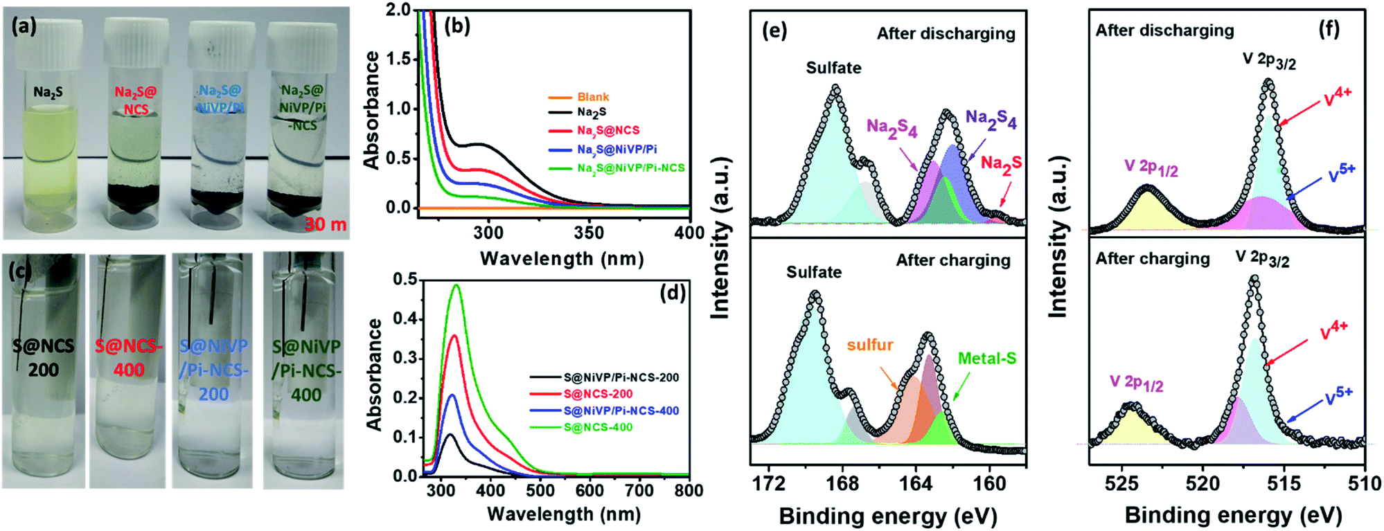 | ||
| Fig. 4 (a) Photographic images of the Na2S solution with various catalysts after 30 minutes, (b) corresponding UV-vis spectra of Na2S solution of Fig. 4a after 30 minutes, (c) photographic images of 2 M aq. Na2SO4 electrolyte with S@NiVP/Pi-NCS and S@NCS anodes after 200 and 400 cycles, and (d) corresponding UV-vis spectra of dissolved polysulfide in 2 M aq. Na2SO4 at various cycling performances, deconvoluted XPS spectra of (e) S 2p and (f) V 2p of S@NiVP/Pi-NCS anode after the charge and discharge cycles. | ||
In addition, to get more insights into the nature of the product during the cycling process, the electrolyte was monitored by in situ UV-Vis spectroelectrochemical studies (Fig. 4c, d and S25, ESI†). The UV-spectra in Fig. 4d, S26 and S27 (ESI†) shows a feeble broad peaks at about 300 nm, 370 nm, and 420 nm corresponding to short-chain polysulfide (S22−–S42−).43,44 Interestingly, the relative increase in the peak intensity was observed after 400 cycles, although no noticeable color change of the electrolyte was observed (Fig. 4c). In comparison, S@NCS shows relatively high absorbance and comparatively a slight yellowish electrolyte compared to S@NiVP/Pi-NCS. The quantitative estimation of sulfur lost by UV-Vis studies (detailed in Fig. S27 and Table S4, ESI†) was found to be 8.65% and 27.2% for S@NiVP/Pi-NCS and S@NCS, respectively, after 400 cycles, which is well complemented by potentiometric titration analysis (Fig. S28 and Table S5, ESI†). From these observations, it is evident that a negligible amount of sulfur is lost even after prolonged 400 cycling, thus signifying that NiVP/Pi-NCS together plays a substantial role in the facile adsorption and conversion of polysulfides to sulfur and vice versa.
To illustrate the chemical interaction between NiVP/Pi and polysulfide after the charge–discharge process, in-depth post analysis by XPS was carried out by retrieving the sample after 400 charge–discharge cycles, followed by thorough washing with deionized water. The XPS survey spectra of S@NiVP/Pi-NCS reveals the presence of all the elements such as Ni, V, P, O, C, and N after both the charge and discharge processes (Fig. S29 and S30, ESI†). After the discharge process, the deconvoluted XPS spectra of S 2p (Fig. 4e) display peaks at 161.9 eV and 163.0 eV corresponding to the formation of lower order polysulfides Na2S2 and Na2S4 along with a peak at 159.8 eV corresponding to Na2S.45,46 On the other hand, on charging, the peak due to polysulfide disappeared and a new peak at 164.3 eV was observed corresponding to elemental sulfur.30 More importantly, another peak observed at 162.5 eV for both the charging and discharging processes is attributed to the formation of the metal sulfides, confirming the interaction of polysulfide with NiVP/Pi. In addition, a high intensity peak at 168–170 eV during charge and discharge shows the presence of sulfate from the electrolyte.
Control experiments with S@NCS demonstrate that the intensity of the S 2p XPS spectra after both the charge and discharge were significantly lower than pristine S@NCS and cycled S@NiVP/Pi-NCS, indicating significant sulfur loss during the stability studies for S@NCS. Further, after discharge, the S 2p XPS spectra mainly show only Na2S4 peaks, and no clear peak due to Na2S was observed. Besides, a distinguishable peak due to elemental sulfur can be seen, possibly due to the incomplete conversion of elemental sulfur into polysulfide. On the other hand, during charging, a peak due to Na2S4 and elemental sulfur was also observed. The intensity of elemental sulfur peak is relatively lower than that of S@NiVP/Pi-NCS, and again, the appearance of Na2S4 shows the incomplete conversion of polysulfide to sulfur (Fig. S31, ESI†). Therefore, the formation of sulfur during charging and polysulfide during the discharge for S@NiVP/Pi-NCS demonstrates an excellent catalytic activity of the NiVP/Pi-NCS host. Further, the BE of S 2p is shifted toward a higher BE in both charging and discharging for S@NiVP/Pi-NCS than S@NCS, signifying a strong interfacial interaction by the NiVP/Pi-NCS host to accelerate the polysulfide redox kinetics and anchor the sodium polysulfide (Fig. S31, ESI†). Further, the deconvoluted Ni 2p XPS spectra shows a minimal change in the BE before and after charging. Similarly, when polysulfides were formed during discharging, the BE of the V 2p XPS spectra shifted to a lower value compared to pristine NiVP/Pi because high-valent vanadium has sufficient vacant sites for interacting with the sulfide of sodium polysulfide (Fig. 4f). As a result, the electron density was transferred from polysulfide to vanadium; hence, the BE decreased and simultaneously, the S 2p BE increases. On the other hand, in charging, when polysulfide is converted back to the sulfur, the electron density reverts back to elemental sulfur; again, the BE of V 2p is shifted to its original position and simultaneously, the BE of the S 2p XPS spectra decrease. These results clearly indicate the crucial role of NiVP/Pi in anchoring and accelerating the polysulfide redox kinetics.
Further, the formation of intermediate polysulfides were analyzed by the S 2p XPS spectra at various discharge potentials; the early appearance of Na2S during discharge demonstrates the faster polysulfide redox kinetics in aqueous electrolyte (detailed in Fig. S32 ESI†). In contrast for non-aqueous Na–S battery (1 M NaClO4 was dissolved in an EC:PC in the volume ratio of 1:1 as the electrolyte), the Na2S species formed at the very end of the discharge along with other dominating polysulfide species confirms the sluggish kinetics of sulfur redox reaction in non-aqueous electrolytes than in aqueous electrolyte (Fig. S33, ESI†). These observations are well supported by EIS and the lower Tafel slope for S@NiVP/Pi-NCS in aqueous electrolyte. The SEM images acquired after the stability studies shows no distinguishable change in the morphology of the catalyst (Fig. S34, ESI†). Further, the existence of polysulfide on the electrode surface was supported by elemental dot mapping (Fig. S35, ESI†) acquired after 400 cycles of the discharge and charge process. As illustrated in Fig. S35 (ESI†), the agglomerated bright spots after discharging signifies the electrostatic charge accumulation on the surface, validating polysulfide formation. Subsequently, on charging, these agglomerated polysulfides were uniformly distributed on the electrode surface due to elemental S formation.
Prior to full cell battery assembly, polysulfide leakage experiments were conducted for both Nafion membrane and Celgard 2400 PP separator (detailed in the ESI†). Experiments were conducted by dissolving various concentrations of polysulfides (Na2S2viz. 2 M, 1 M, 0.5 M) in 2 M Na2SO4 and placed in a glass vial covered with a Nafion membrane (detailed in ESI†) and were inverted and placed in an airtight closed glass containing 2 M Na2SO4 aqueous electrolyte. As observed from Fig. 5a–c, no significant color change was observed in the outer electrolyte even after resting for 20 days using a Nafion membrane. Further, to clarify more on the role of the Nafion membrane in inhibiting the polysulfide dissolution, we have performed additional polysulfide leakage experiments with a Celgard 2400 PP separator by dissolving 0.5 M polysulfide in 2 M Na2SO4 aqueous electrolyte in a small vial, which is then inverted in aqueous 2 M Na2SO4 solution. As shown in Fig. S36,† the yellow color is visible in the outer vial with a Celgard 2400 PP separator, while the solution remains colorless with the Nafion membrane. These results shows that due to repulsion between the negatively charged membranes (SO3 groups) and negatively charged polysulfide, the polysulfide dissolution is inhibited, which should result in high cycling stability (detailed in ESI, Fig. S36, ESI†).
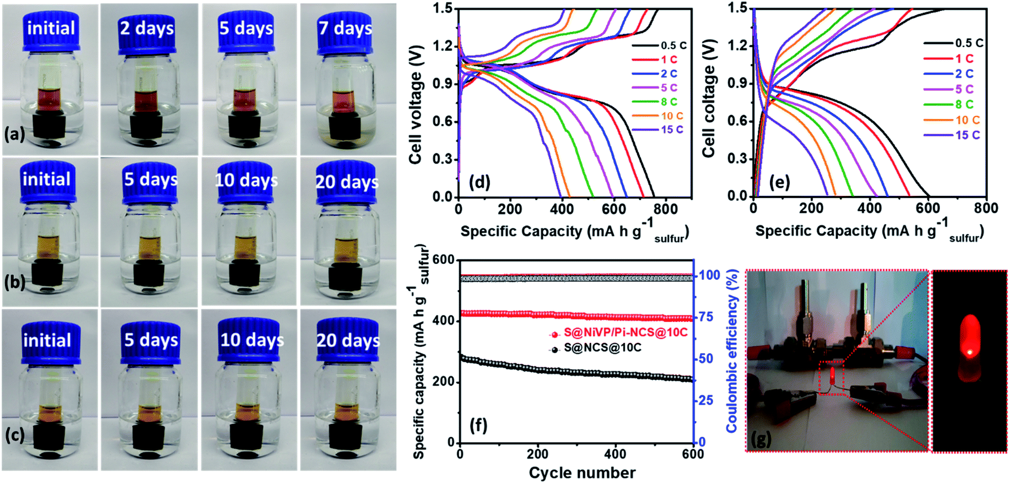 | ||
| Fig. 5 Nafion membrane polysulfide leakage test with different salt concentrations after variable resting times: (a) 2 M polysulfide dissolved in a 2 M Na2SO4 aqueous electrolyte in a small vial and then inverted into 2 M Na2SO4 in water, (b) 1 M polysulfide dissolved in a 2 M Na2SO4 aqueous electrolyte and then placed in 2 M Na2SO4 in water, (c) 0.5 M polysulfide dissolved in a 2 M Na2SO4 aqueous electrolyte and then placed in a 2 M Na2SO4 in water, galvanostatic charge–discharge curves of full cell battery assembled using Nafion membrane with (d) S@NiVP/Pi-NCS anode + Na0.44MnO2 cathode and (e) S@NCS anode + Na0.44MnO2 cathode at various C-rates, (f) corresponding battery cycling performances and coulombic efficiency at 10C respectively over 600 cycles in 2 M aq. Na2SO4, (g) demonstration of two aqueous Na-ion/S battery consisting of S@NiVP/Pi-NCS anode and Na0.44MnO2 cathode powering LED. | ||
Hence, full cell battery performance was analyzed further by assembling a battery using the Swagelok cell with a two-electrode setup with the proposed S@NiVP/Pi-NCS anode and a Na0.44MnO2 cathode in 2 M Na2SO4 electrolyte using Nafion membrane as the separator. The loading of cathode to anode was fixed at 4.14:1, and full cell analysis was performed in the potential range from 0 V to 1.5 V. The galvanostatic charge–discharge analysis at 0.5C (Fig. 5d, S38 and S39, ESI†) displays a very high initial specific capacity of 756 mA h g−1 based on the weight of sulfur and 98.3 mA h g−1 capacity depends on the total electrodes weight. In addition, the battery demonstrates a high energy density of 84 W h kg−1 based on the total electrode weight which is superior even when compared to the reported ARSIBS full cell (Table S7, ESI†). On the other hand, the S@NCS anode and the Na0.44MnO2 cathode battery cell delivers an initial capacity of 605 mA h g−1 depending on the weight of sulfur and 82.3 mA h g−1 with respect to total electrode weight (Fig. 5e) with an energy density of 62 W h kg−1. Further, the rate performance of the full cell was analyzed by subjecting it to various C rates.
Interestingly, both the full cell (S@NiVP/Pi-NCS and S@NCS anodes with the Na0.44MnO2 cathode) successfully operated at high C rate (15C) and achieved a capacity of 395 mA h g−1 and 253 mA h g−1, respectively, demonstrating the ability of the catalyst to operate under high C rates (Fig. 5d, e, S38 and S39A, ESI†). Further, the proposed S@NiVP/Pi-NCS is a promising anode, exhibiting an exceptionally high-rate performance witnessed from 99.72% coulombic efficiency (Fig. 5f and S39B, ESI†) and 95% of capacity retention even after 600 prolonged cycles at a very high C-rate of 10C compared to S@NCS (68%). Further, the full cell assembled with the S@NiVP/Pi-NCS anode and the Na0.44MnO2 cathode retains 78.3% capacity after 100 cycles at 0.5C. However, the obtained results are inferior to the stability response at 10C. Considering the prime challenge of using the sulfur-based electrode in the aqueous electrolyte, the S@NiVP/Pi-NCS anode and the full cell show good performance even at a lower C rate (Fig. S40A, ESI†).
Further, to understand the role of the Nafion membrane to inhibit the polysulfide dissolution, we have performed additional experiments by assembling a full cell with Celgard 2400 separator. As shown in Fig. S40B (ESI†), the full cell assembled with the Celgard 2400 separator retains only 93% capacity after 400 cycles at 10C. The cell assembled with the Nafion membrane retains 96.8% of capacity after similar number of cycles and at similar C rate. These results prove that the Nafion membrane inhibits polysulfide dissolution and plays a crucial role in maintaining durable cycling stability. Besides, from developing a cost-effective and safer energy storage system toward practical application, we demonstrated a device based on two aqueous Na-ion/S full cells. After a full charge when these batteries connected in series powering a glowing red LED shown in Fig. 5g. Further, the assembled device can power an LED for a longer duration, demonstrating the practical applicability of such types of devices.
Conclusions
In summary, we demonstrated novel high-capacity aqueous Na-ion/S batteries with the S@NiVP/Pi-NCS anode using 70% of elemental sulfur. The synthesized catalyst combines the merits of high conductivity and entrapment ability of NCS with high anchoring and polysulfide redox kinetic ability of polar NiVP/Pi to accomplish smooth diffusion-immobilization and accelerated conversion of polysulfide. The high intrinsic catalytic activity of NiVP/Pi-NCS is mainly due to high conductivity, facile electron transfer, high polysulfide conversion kinetics, and good anchoring of polysulfides even in aqueous media. Various electrochemical, spectroscopic, and visualization studies confirmed that the anode could inhibit polysulfide dissolution in the aqueous electrolyte due to its favorable anchoring sites. Moreover, the accelerated redox kinetics toward polysulfide conversion at the S@NiVP/Pi-NCS anode enables the catalyst to operate at a very high current density of 10C. The S@NiVP/Pi-NCS anode delivers an outstanding capacity of 826 mA h g−1 at 0.5C with an excellent cycling performance over 400 cycles at a very high current density of 10C. Further, the full cell was assembled using the S@NiVP/Pi-NCS anode, and the Na0.44MnO2 cathode demonstrates an excellent initial capacity of 756 mA h g−1 and a remarkable energy density of 84 W h kg−1 at 0.5C with 95% of capacity retention over 600 cycles at 10C. More importantly two fully charged cells connected in series are able to power a LED, thus demonstrating its practical application. We believe that the present work paves the way for designing a low cost and highly stable anode for aqueous sodium ion battery technology for large storage applications.Author contributions
Mukesh Kumar: conceptualization, methodology, software, data curation, writing – original draft, visualization, investigation, formal analysis. Neha Thakur: methodology. Debaprasad Mandal: conceptualization. Tharamani C. Nagaiah: conceptualization, methodology, supervision, funding acquisition. Ankur Bordoloi: TEM measurements. Ashok Yadav, Shambhunath Jha, Dibyendu Bhattacharyya: XANES, EXAFS measurement.Conflicts of interest
There are no conflicts to declare.Acknowledgements
T. C. Nagaiah thanks Science and Engineering Research Board (SERB, CRG/2018/004478). D. Mandal thanks Council of Scientific & Industrial Research (CSIR) India (02(1115)/20/EMR-II).References
- Y.-S. Su, Y. Fu, T. Cochell and A. Manthiram, Nat. Commun., 2013, 4, 1–8 Search PubMed
.
- Y. Ansari, S. Zhang, B. Wen, F. Fan and Y. M. Chiang, Adv. Energy Mater., 2019, 9, 1802213 CrossRef
- G. Li, T. Ouyang, T. Xiong, Z. Jiang, D. Adekoya, Y. Wu, Y. Huang and M.-S. J. T. Balogun, Carbon, 2021, 174, 1–9 CrossRef CAS
- S. Zhou, P. Huang, T. Xiong, F. Yang, H. Yang, Y. Huang, D. Li, J. Deng and M. S. Balogun, Small, 2021, 2100778 CrossRef CAS PubMed
- N. Deng, Y. Liu, Q. Li, J. Yan, W. Lei, G. Wang, L. Wang, Y. Liang, W. Kang and B. Cheng, Energy Storage Mater., 2019, 23, 314–349 CrossRef
- M. Liu, N. Deng, J. Ju, L. Fan, L. Wang, Z. Li, H. Zhao, G. Yang, W. Kang and J. Yan, Adv. Funct. Mater., 2019, 29, 1905467 CrossRef CAS
- Y. Huang, H. Yang, T. Xiong, D. Adekoya, W. Qiu, Z. Wang, S. Zhang and M.-S. Balogun, Energy Storage Mater., 2020, 25, 41–51 CrossRef
- T. Perveen, M. Siddiq, N. Shahzad, R. Ihsan, A. Ahmad and M. I. Shahzad, Renewable Sustainable Energy Rev., 2020, 119, 109549 CrossRef CAS
- T. Shao, C. Li, C. Liu, W. Deng, W. Wang, M. Xue and R. Li, J. Mater. Chem. A, 2019, 7, 1749–1755 RSC
- A. Tron, Y. N. Jo, S. H. Oh, Y. D. Park and J. Mun, ACS appl. Mater. Interfaces, 2017, 9, 12391–12399 CrossRef CAS PubMed
- Z. Li, D. Young, K. Xiang, W. C. Carter and Y. M. Chiang, Adv. Energy Mater., 2013, 3, 290–294 CrossRef CAS
- D. Chao, W. Zhou, F. Xie, C. Ye, H. Li, M. Jaroniec and S.-Z. Qiao, Sci. adv., 2020, 6, eaba4098 CrossRef CAS PubMed
- L. Suo, O. Borodin, T. Gao, M. Olguin, J. Ho, X. Fan, C. Luo, C. Wang and K. Xu, Science, 2015, 350, 938–943 CrossRef CAS PubMed
- L. Jiang, L. Liu, J. Yue, Q. Zhang, A. Zhou, O. Borodin, L. Suo, H. Li, L. Chen and K. Xu, Adv. Mater., 2020, 32, 1904427 CrossRef CAS PubMed
- K. Nakamoto, Y. Kano, A. Kitajou and S. Okada, J. Power Sources, 2016, 327, 327–332 CrossRef CAS
- P. Lei, K. Liu, X. Wan, D. Luo and X. Xiang, Chem. Commun., 2019, 55, 509–512 RSC
- F. Zhang, W. Li, X. Xiang and M. Sun, J. Electroanal. Chem., 2017, 802, 22–26 CrossRef CAS
- X. Zhang, Z. Hou, X. Li, J. Liang, Y. Zhu and Y. Qian, J. Mater. Chem. A, 2016, 4, 856–860 RSC
- J. E. Fonsaca, S. H. Domingues, E. S. Orth and A. J. Zarbin, Chem. Commun., 2020, 56, 802–805 RSC
- J. Wang, C. Mi, P. Nie, S. Dong, S. Tang and X. Zhang, J. Electroanal. Chem., 2018, 818, 10–18 CrossRef CAS
- P. Jiang, Z. Lei, L. Chen, X. Shao, X. Liang, J. Zhang, Y. Wang, J. Zhang, Z. Liu and J. Feng, ACS Appl. Mater. Interfaces, 2019, 11, 28762–28768 CrossRef CAS PubMed
- Y. Yuan, D. Bin, X. Dong, Y.-G. Wang, C. Wang and Y. Xia, ACS Sustain. Chem. Eng., 2020, 8, 3655–3663 CrossRef CAS
- D. Baster, E. Oveisi, P. Mettraux, S. Agrawal and H. H. Girault, Chem. Commun., 2019, 55, 14633–14636 RSC
- L. Ke, J. Dong, B. Lin, T. Yu, H. Wang, S. Zhang and C. Deng, Nanoscale, 2017, 9, 4183–4190 RSC
- S. Qiu, X. Wu, M. Wang, M. Lucero, Y. Wang, J. Wang, Z. Yang, W. Xu, Q. Wang and M. Gu, Nano Energy, 2019, 64, 103941 CrossRef CAS
- F. Wu, T. P. Pollard, E. Zhao, Y. Xiao, M. Olguin, O. Borodin and G. Yushin, Energy Environ. Sci., 2018, 11, 807–817 RSC
- T. Zhou, W. Lv, J. Li, G. Zhou, Y. Zhao, S. Fan, B. Liu, B. Li, F. Kang and Q.-H. Yang, Energy Environ. Sci., 2017, 10, 1694–1703 RSC
- X. Wu, X. Yuan, J. Yu, J. Liu, F. Wang, L. Fu, W. Zhou, Y. Zhu, Q. Zhou and Y. Wu, Nanoscale, 2017, 9, 11004–11011 RSC
- J. Shao, X. Li, L. Zhang, Q. Qu and H. Zheng, Nanoscale, 2013, 5, 1460–1464 RSC
- C. Yang, L. Suo, O. Borodin, F. Wang, W. Sun, T. Gao, X. Fan, S. Hou, Z. Ma and K. Amine, Proc. Natl. Acad. Sci. U. S. A., 2017, 114, 6197–6202 CrossRef CAS PubMed
- B. Tekin, S. Sevinc, M. Morcrette and R. Demir-Cakan, Energy Technol., 2017, 5, 2182–2188 CrossRef CAS
- S. Sevinc, B. Tekin, A. Ata, M. Morcrette, H. Perrot, O. Sel and R. Demir-Cakan, J. Power Sources, 2019, 412, 55–62 CrossRef CAS
- A. Tiwari, V. Singh, D. Mandal and T. C. Nagaiah, J. Mater. Chem. A, 2017, 5, 20014–20023 RSC
- Z. Li, D. Young, K. Xiang, W. C. Carter and Y. M. Chiang, Adv. Energy Mater., 2013, 3, 290–294 CrossRef CAS
- K. Fan, H. Chen, Y. Ji, H. Huang, P. M. Claesson, Q. Daniel, B. Philippe, H. Rensmo, F. Li and Y. Luo, Nat. Commun., 2016, 7, 1–9 Search PubMed
- H. W. Park, J. S. Chae, S.-M. Park, K.-B. Kim and K. C. Roh, Met. Mater. Int, 2013, 19, 887–894 CrossRef CAS
- Y. Song, W. Zhao, L. Kong, L. Zhang, X. Zhu, Y. Shao, F. Ding, Q. Zhang, J. Sun and Z. Liu, Energy Environ. Sci., 2018, 11, 2620–2630 RSC
- D. Wang, Q. Li, C. Han, Q. Lu, Z. Xing and X. Yang, Nat. Commun., 2019, 10, 1–12 CrossRef PubMed
- P. F. Liu, X. Li, S. Yang, M. Y. Zu, P. Liu, B. Zhang, L. R. Zheng, H. Zhao and H. G. Yang, ACS Energy Lett., 2017, 2, 2257–2263 CrossRef CAS
- N. Wang, Y. Wang, Z. Bai, Z. Fang, X. Zhang, X. Xu, Y. Du, S. X. Dou and G. Yu, Energy Environ. Sci., 2020, 13, 562–570 RSC
- T. Swamy and Y.-M. Chiang, J. Electrochem. Soc., 2015, 162, A7129–A7134 CrossRef CAS
- E. P. Randviir, Electrochim. Acta, 2018, 286, 179–186 CrossRef CAS
- M. Zhang, J. Guan, Y. Tu, S. Chen, Y. Wang, S. Wang, L. Yu, C. Ma, D. Deng and X. Bao, Energy Environ. Sci., 2020, 13, 119–126 RSC
- M. Kumar and T. C. Nagaiah, J. Mater. Chem. A, 2022, 10, 7048–7057 RSC
- M. Fantauzzi, B. Elsener, D. Atzei, A. Rigoldi and A. Rossi, RSC Adv., 2015, 5, 75953–75963 RSC
- S. Wei, S. Xu, A. Agrawral, S. Choudhury, Y. Lu, Z. Tu, L. Ma and L. A. Archer, Nat. Commun., 2016, 7, 11722 CrossRef CAS PubMed
Footnote |
| † Electronic supplementary information (ESI) available. See https://doi.org/10.1039/d2ta02296f |
| This journal is © The Royal Society of Chemistry 2022 |