
Electrocatalytic valorization of 5-hydroxymethylfurfural coupled with hydrogen production using tetraruthenium-containing polyoxometalate-based composites†
Hui
Zhou
a,
Yuanyuan
Dong
 *a,
Xing
Xin
a,
Manzhou
Chi
a,
Tinglu
Song
b and
Hongjin
Lv
*a
*a,
Xing
Xin
a,
Manzhou
Chi
a,
Tinglu
Song
b and
Hongjin
Lv
*a
aMOE Key Laboratory of Cluster Science, Beijing Key Laboratory of Photoelectroic/Electrophotonic Conversion, School of Chemistry and Chemical Engineering, Beijing Institute of Technology, Beijing 102488, P. R. China. E-mail: dyy1111@bit.edu.cn; hlv@bit.edu.cn
bExperimental Center of Advanced Materials, School of Materials Science & Engineering, Beijing Institute of Technology, China
First published on 20th June 2022
Abstract
Electrocatalytic biomass valorization represents a promising route to produce sustainable and carbon-neutral products, especially when coupled with hydrogen production. Here we report a Ru4/PEI-rGO electrocatalyst, prepared by electrostatic integration of a tetraruthenium-containing polyoxometalate, Rb8K2[Ru4(μ-O)4(μ-OH)2(H2O)4(γ-SiW10O36)2]·25H2O (Ru4), with polyethyleneimine (PEI) modified rGO, which can efficiently electrocatalyze biomass-derived 5-hydroxymethylfurfural (HMF) to value-added furanic products simultaneously coupled with H2 production in near neutral media. Under minimally optimized conditions, the conversion of HMF and the yield of H2 reached 50.8% and 55.4 μmol after 6 hour electrocatalysis at 0.94 V vs. Ag/AgCl, respectively. 2,5-Diformylfuran (DFF) was detected as the dominant oxidation product with a selectivity of 66.2%. The faradaic efficiencies (FEs) of the anode and cathode reached 97.0 ± 3% and 100.2 ± 2%, respectively. In the presence of the 2,2,6,6-tetramethylpiperidinyloxyl (TEMPO) additive, the conversion of HMF reached 99.7%, and the distribution of the oxidation product has been greatly altered, wherein furanic carboxyl products are dominant. Various electrochemical characterization studies and spectrogram analyses, especially Fourier Transformed Alternating Current (FTAC) voltammetry, were employed to disclose that RuV centers were catalytically active species, and the three-electron oxidized Ru4 species are responsible for the excellent electrocatalytic activity. Long-term electrocatalysis demonstrated that the present Ru4/PEI-rGO composite possessed good stability for catalysis.
 Yuanyuan Dong | Yuanyuan Dong received her PhD degree from Tianjin University under the supervision of Prof. Xinbin Ma. After finishing the postdoctoral training with Prof. Shijun Liao at South China University of Technology and Prof. Qi Chen at Beijing Institute of Technology (BIT), she joined the School of Chemistry and Chemical Engineering at BIT as an Assistant Professor. Her current research is focused on the material design of polyoxometalate-semiconductor composites, electro-/photocatalysis for renewable energy conversion, and value-added transformation of organic chemicals. |
Introduction
With the increasing global demand for environmental protection and energy requirements, the development of renewable energy, such as the electrocatalytic conversion of biomass, has inspired great research interest.1–5 HMF, as a top-rated biomass-derived building block chemical, can be used as a versatile precursor for the production of fine chemicals, plastics, pharmaceuticals, and liquid fuels.6 HMF can be oxidized to a wide range of chemicals including DFF, 5-hydroxymethyl-2-furan-carboxylic acid (HMFCA), 5-formyl-2-furancarboxylic acid (FFCA) and 2,5-furandicarboxylic acid (FDCA).7 During the past few years, a large number of electrocatalytic/photo electrocatalytic systems have been reported, including noble metal catalysts (Pt,8 Au/Pd,9 and Ru pincer10), non-noble metal catalysts (NiO/Ni(OH)2,11 Ni NPs,12 Ni2P,6 NixB,13 NiCo2O4,14 CuNi(OH)2/C,15 and BiVO4,16 and metal-free catalysts (B/N–C17). These catalysts were reported to effectively catalyze the oxidation of HMF to FDCA in strong alkali electrolyte via path II (Scheme 1). Interestingly, DFF is also a high value-added platform chemical and can be used either as a monomer, or as starting material in the synthesis of furan-urea resins, foams, binders, and pharmaceuticals.18 However, only a few reports about the oxidation of HMF via path I exist (Scheme 1).19 Additionally, it is also an interesting topic to regulate the product distribution (furanic aldehyde and furanic carboxyl) during the valorization of HMF, whereas there are rarely related reports so far according to our knowledge. Therefore, it is highly desirable to develop efficient electrocatalysts for the electrooxidation of HMF with adjustable value-added products.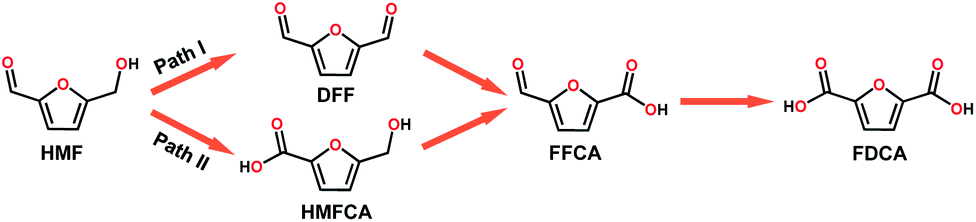 | ||
| Scheme 1 Two possible pathways of HMF oxidation to their corresponding aldehydes and acids. | ||
Polyoxometalates (POMs), a large class of early transition-metal (e.g. VV, NbV, TaV, MoVI, and WVI) oxygen-anion clusters with usually d0 electronic configuration,20 have been considered as one of the promising multi-electron transfer catalysts due to their rich redox chemistry, compositional tunability, and excellent electron reservoir capacity. POMs have been widely applied in photo/electrocatalysis fields including the HER,21–24 OER,25–27 and CO2RR.28–30 Additionally, POMs ((KCl4)Na7[(β-CD)3(SiW12O40)]·9H2O,31 (THA)3[SbW9O33(RSiO)3Ti(OiPr)],32 (Gd4(H2O)26[WZn{Cu(H2O)}2(ZnW9O34)2]·24H2O,33 [Co(BBPTZ)3][HPMo12O40]·24![[thin space (1/6-em)]](https://www.rsc.org/images/entities/char_2009.gif) H2O,34 [TMGHA]2.4H0.6PW12O40,35 and HxPMo12O40⊂H4Mo72Fe30(CH3COO)15O25436 were also reported to effectively oxidize alcohols, alkenes, and thiophene with H2O2 or O2 as an oxidant at appropriate temperatures. However, there are few reports on the electrocatalytic oxidation of biomass derivatives using POMs as electrocatalysts, especially while integrating with hydrogen production to construct a more valuable electrochemical coupling system.37 Moreover, POMs, with a specific elemental composition and distinct geometric structure, could be easily used as a model catalyst to investigate catalytically active sites and the reaction mechanism. Therefore, it is an interesting topic to develop POM-based composite electrocatalysts to convert biomass into high value-added products and simultaneously produce hydrogen.
H2O,34 [TMGHA]2.4H0.6PW12O40,35 and HxPMo12O40⊂H4Mo72Fe30(CH3COO)15O25436 were also reported to effectively oxidize alcohols, alkenes, and thiophene with H2O2 or O2 as an oxidant at appropriate temperatures. However, there are few reports on the electrocatalytic oxidation of biomass derivatives using POMs as electrocatalysts, especially while integrating with hydrogen production to construct a more valuable electrochemical coupling system.37 Moreover, POMs, with a specific elemental composition and distinct geometric structure, could be easily used as a model catalyst to investigate catalytically active sites and the reaction mechanism. Therefore, it is an interesting topic to develop POM-based composite electrocatalysts to convert biomass into high value-added products and simultaneously produce hydrogen.
Herein, we report the preparation of a Ru4/PEI-rGO composite via the electrostatic interaction of Ru4 POM and PEI modified rGO (Scheme 2a), which could efficiently electrocatalyze oxidation of HMF to value-added furanic products simultaneously coupled with hydrogen generation (Scheme 2b). The reaction parameters during the preparation of catalysts and the electrocatalytic process were further optimized, including the amount of PEI, the content of Ru4 POM, the loading quantity of the composite electrocatalyst onto carbon cloth, and the reaction atmosphere. The positive influences on electrocatalytic activities of the additive TEMPO were also investigated. Various electrochemical characterization studies and spectrogram analyses, especially FTAC voltammetry, were employed to disclose the catalytically active species and further get insight into the electrocatalytic oxidation mechanism of HMF.
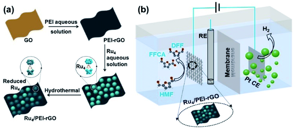 | ||
| Scheme 2 The schematic diagrams of (a) the preparation route of Ru4/PEI-rGO and (b) the electrocatalytic conversion of HMF coupled with hydrogen production system. | ||
Results and discussion
The preparation of Ru4/PEI-rGO is described in detail in the Experimental section. The hydrothermal temperature was determined based on the results of thermogravimetric (TG) and differential thermal analysis (DTA) (Fig. 1a). A weight loss of 5.87% is associated with the loss of 22 water molecules terminally bound to the RuIV centers as well as the accompanied endothermic process. The Ru4-containing residue after TG analysis could be re-dissolved in water as a homogeneous and transparent solution (Fig. S1†), indicating that the molecular structure of Ru4 POM could be kept intact below 400 °C. Scheme 2a depicts the schematic synthetic diagram of Ru4/PEI-rGO via electrostatic self-assembly, as revealed by the changes in zeta potential (ζ) (Fig. 1b).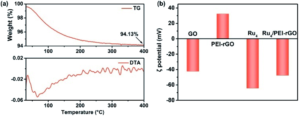 | ||
| Fig. 1 (a) TG analysis (top) and DTA data (bottom) of the Ru4/PEI-rGO sample. (b) Zeta potentials of GO, PEI-rGO, Ru4, and Ru4/PEI-rGO samples. | ||
Fig. 2 shows the Fourier transform infrared (FT-IR) spectra of GO, PEI-rGO, Ru4/PEI-rGO, and Ru4 samples. The characteristic bands at 1052, 1225 cm−1, 1401 and 1720 cm−1 marked with light yellow block were attributed to the vibration bands of C–O–C, O–H and C![[double bond, length as m-dash]](https://www.rsc.org/images/entities/char_e001.gif) O for GO, respectively.38,39 After grafting with PEI molecules, the bands at 1052 and 1720 cm−1 completely disappear, along with obvious weakening of two peaks at 1401 (νO–H) and 1225 (νC–O) cm−1. The strong band at 1618 cm−1 in GO is replaced by a band at 1640 cm−1 (light blue block) in PEI-rGO, which is attributed to the formation of amide bonds because of the reduction of GO by PEI molecules. In addition, a new band at 1460 cm−1 (light blue block) appears in PEI-rGO which is assigned to the C–N stretching vibration.40 These observations fully indicate the successful grafting of PEI molecules onto the GO surface, confirmed by the changes in ζ from −42.28 mV of GO to 32.35 mV of PEI-rGO (Fig. 1b). Additionally, the characterization bands marked with grey block identify the typical features of γ-disubstituted polytungstates (940 cm−1 WOd stretching; 850 cm−1 W–Ob–W stretching of corner-sharing octahedron; 805–730 cm−1 W–Oc–W stretching of corner-sharing octahedron)41 and a characteristic Ru–O–Ru mode (487 cm−1),42 showing the successful immobilization of Ru4 onto the PEI-rGO surface, which is consistent with the changes in ζ from the 32.35 mV of PEI-rGO to −47.54 mV of Ru4/PEI-rGO (Fig. 1b).
O for GO, respectively.38,39 After grafting with PEI molecules, the bands at 1052 and 1720 cm−1 completely disappear, along with obvious weakening of two peaks at 1401 (νO–H) and 1225 (νC–O) cm−1. The strong band at 1618 cm−1 in GO is replaced by a band at 1640 cm−1 (light blue block) in PEI-rGO, which is attributed to the formation of amide bonds because of the reduction of GO by PEI molecules. In addition, a new band at 1460 cm−1 (light blue block) appears in PEI-rGO which is assigned to the C–N stretching vibration.40 These observations fully indicate the successful grafting of PEI molecules onto the GO surface, confirmed by the changes in ζ from −42.28 mV of GO to 32.35 mV of PEI-rGO (Fig. 1b). Additionally, the characterization bands marked with grey block identify the typical features of γ-disubstituted polytungstates (940 cm−1 WOd stretching; 850 cm−1 W–Ob–W stretching of corner-sharing octahedron; 805–730 cm−1 W–Oc–W stretching of corner-sharing octahedron)41 and a characteristic Ru–O–Ru mode (487 cm−1),42 showing the successful immobilization of Ru4 onto the PEI-rGO surface, which is consistent with the changes in ζ from the 32.35 mV of PEI-rGO to −47.54 mV of Ru4/PEI-rGO (Fig. 1b).
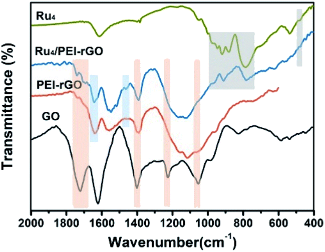 | ||
| Fig. 2 FT-IR spectra of GO, PEI-rGO, Ru4, and Ru4/PEI-rGO samples. | ||
Ru4/PEI-rGO displayed a transparent nanosheet morphology as illustrated by the transmission electron microscopy (TEM) images (Fig. 3 and S2†). Energy-dispersive X-ray (EDX) elemental analysis confirmed the presence of Ru, W, Si, and Rb elements (Fig. S3†). Moreover, the fine Ru4 POM clusters were uniformly distributed on the PEI-rGO surface as evidenced by high-resolution TEM (left bottom image in Fig. 3) and high-angle annular dark-field scanning transmission electron microscopy (HAADF-STEM) and element mapping analysis (Fig. 3).
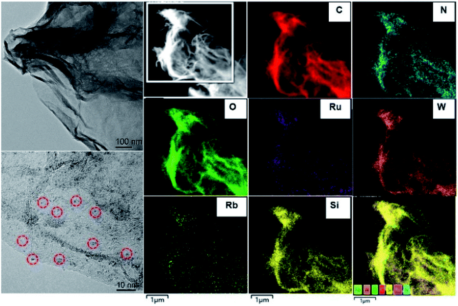 | ||
| Fig. 3 TEM and HAADF-STEM images and element mapping for the Ru4/PEI-rGO electrocatalyst. | ||
To further confirm the elemental composition and chemical oxidation state, XPS measurements were conducted on Ru4 POM and the Ru4/PEI-rGO composite. The W 4f, Ru 3p, Si 2p, and O 1s signals were clearly detected in the XPS survey spectra (Fig. S4†). The peaks at binding energies of 462.5 eV (Ru 3p3/2) and 484.5 eV (Ru 3p1/2) were attributed to the RuIV species (Fig. 4a). The peaks at 35.0 eV (W 4f7/2) and 37.1 eV (W 4f5/2) were assigned to the WVI species (Fig. 4b), which is consistent with the literature report.41 After immobilization, both the Ru 3p and W 4f XPS signals shifted negatively to lower binding energies, indicating the partially reduction of Ru4 POM caused by the electron density shift from PEI-rGO to Ru4 POM.
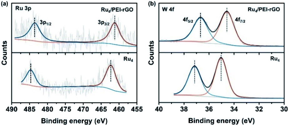 | ||
| Fig. 4 The high-resolution (a) Ru 3p and (b) W 4f XPS spectra of Ru4 and Ru4/PEI-rGO. | ||
The electrocatalytic activity of the Ru4/PEI-rGO composite was first evaluated by cyclic voltammetry (CV) and linear sweep voltammetry (LSV) analyses (Fig. 5a and b) in pH 6 HAc/NaAc buffer solution (0.5 M). Compared with rGO and PEI-rGO, the Ru4/PEI-rGO composite exhibited obvious oxidation current at a relatively more negative onset potential. Additionally, the open-circuit potential also shifted to a more negative value (0.26 V vs. Ag/AgCl, Fig. 5a), indicating that Ru4 POM has been reduced spontaneously by the HMF substrate. These observations imply that the Ru4/PEI-rGO composite shows efficient electrocatalytic activity towards HMF oxidation. Upon electrocatalysis for 6 hour at 0.94 V vs. Ag/AgCl (Fig. 5c), the anode oxidation products were detected and quantified by high performance liquid chromatography (HPLC) (Fig. S5†), achieving 50.8% conversion of the HMF substrate with a total selectivity of anodic furanic products of 95.5%. Additionally, DFF dominated the anodic oxidation products with a selectivity of 66.2% (Fig. 5d). For rGO and PEI-rGO as control electrocatalysts, the yield of DFF is very low in spite of their high HMF conversion, which could be ascribed to the deep mineralization of HMF as illustrated by the extremely lower carbon balance (Xc) and the GC spectra of the gaseous products at the anode chambers (Fig. S6†). In terms of the cathodic product, a H2 yield of 55.4 μmol was obtained in the Ru4/PEI-rGO-electrocatalytic system. Additionally, faradaic efficiencies of the anode and cathode were basically consistent, indicating that the oxidation of HMF over Ru4/PEI-rGO has effectively proceeded via the electrocatalytic process (Fig. 5e). Additionally, electrochemical impedance spectroscopy (EIS) measurements were performed at 0.94 V vs. Ag/AgCl for further investigating the electrochemical kinetics of HMF oxidation. As shown in Fig. 5f, the similar resistance indicated that the modification of PEI did not influence the electron transfer between HMF and rGO during the electrocatalysis. Moreover, the smaller resistance implied a fast electron transfer between Ru4 and HMF, and therefore Ru4/PEI-rGO exhibited efficient electrocatalytic activity towards HMF oxidation.
 | ||
| Fig. 5 (a) CV and (b) LSV curves of rGO, PEI-rGO and Ru4/PEI-rGO electrocatalysts. (c) The i–t response curve of Ru4/PEI-rGO at 0.94 V vs. Ag/AgCl for 6 h. The conversion of HMF, the selectivity of liquid products and the yield of H2 (d) and FE (e) of products for rGO, PEI-rGO and Ru4/PEI-rGO electrocatalysts upon bulk electrolysis at 0.94 V vs. Ag/AgCl for 6 h at room temperature. (f) Nyquist plots for rGO, PEI-rGO and Ru4/PEI-rGO in 5 mM HMF (0.5 M pH = 6 HAc/NaAc) at 0.94 V vs. Ag/AgCl and the equivalent circuit diagram. | ||
We further optimized the reaction parameters during the preparation of catalysts and the electrocatalytic process, including the amount of PEI, the content of Ru4 POM, the loading quantity of the composite electrocatalyst onto carbon cloth, the reaction atmosphere (Tables S1 and S2† and Fig. 6 and S7†), etc. Despite the higher conversion of HMF in an O2 atmosphere, the faradaic efficiencies and the selectivity of oxidation products are inferior to those in an air atmosphere (Fig. 6a and b). Therefore, the subsequent electrocatalysis tests were all conducted in an air atmosphere using the above-mentioned optimized parameters. Additionally, the amount of Ru was determined to be 2.4 wt% for the optimized Ru4/PEI-rGO electrocatalyst by inductively coupled plasma (ICP), which is highly cost-effective compared to the noble metal alloy-based electrocatalysts reported in the literature with similar electrocatalytic activities.19 Compared with the reported noble metal-based electrocatalysts, Ru4/PEI-rGO used in this work exhibited significant advantages in the electrooxidation of HMF to DFF at near-neutral electrolyte (Table S3†).
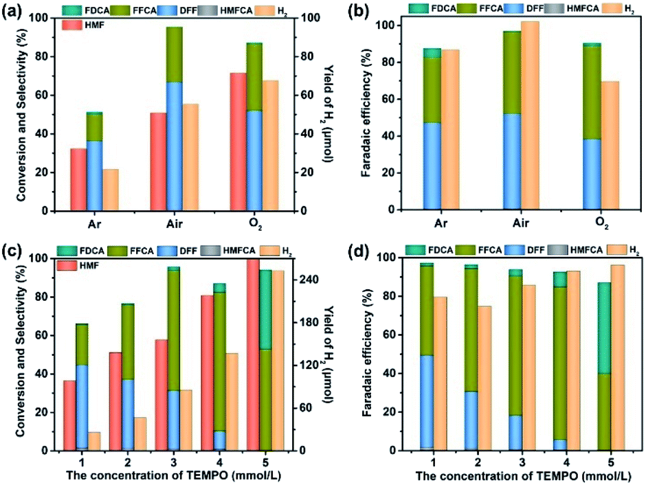 | ||
| Fig. 6 The effects of the reaction atmosphere (a and b) and concentration of TEMPO (c and d) on the electrocatalytic activities of Ru4/PEI-rGO. | ||
Careful inspection of the CV and LSV curves of the Ru4/PEI-rGO-based electrode reveals an obvious oxidation peak at 0.7 V, identifying the indirect oxidation of HMF. It can be proposed that Ru4 is first electrooxidized to its active oxidizing state that could further oxidize HMF during the electrocatalytic process. The redox chemistry and multi-electron transfer capacity of POMs largely depend on the pH, applied voltage, and the electrolyte solution;43 we thus investigated the influences of these parameters on the electrocatalytic activity. As shown in Table 1 (entries 1–3), the conversion of HMF gradually increased with increasing pH value, and DFF is still the dominant anodic oxidation product, whereas the selectivity of FFCA was gradually enhanced which could be attributed to the favorable formation of carboxyl products under alkaline conditions.44 Given the higher furanic yield and faradaic efficiencies, the HAc/NaAc buffer solution (0.5 M) at pH 6 was selected as the optimized electrolyte. Then, the electrolysis has further been conducted at different applied voltages (Table 1, entries 2, 4, and 5). As shown by the experimental results, the yields of furanic products and H2 gradually increased with the increment of applied voltages, which is more obvious in the lower voltage range. To avoid the oxygen evolution competing reaction, an applied voltage of 0.94 V was used for HMF electrooxidation.
| Entry | Conditions | HMF | HMFCA | DFF | FFCA | FDCA | Furanic | FE of anode (%) | H2 | |||||
|---|---|---|---|---|---|---|---|---|---|---|---|---|---|---|
| Con. (%) | Sel. (%) | FE (%) | Sel. (%) | FE (%) | Sel. (%) | FE (%) | Sel. (%) | FE (%) | Sel. (%) | Yield (μmol) | FE (%) | |||
| a Conditions: 0.5 M HAc/NaAc buffer solution, HMF (5 mM), Ru4/PEI-rGO catalysts (0.5 mg), bulk electrocatalysis for 6 h at applied voltage vs. Ag/AgCl. | ||||||||||||||
| 1 | pH 4, 0.94 V | 33.5 | 0 | 0 | 41.0 | 67.5 | 6.7 | 21.9 | 0 | 0 | 47.6 | 89.4 | 11.3 | 86.4 |
| 2 | pH 6, 0.94 V | 50.8 | 0.7 | 0.6 | 66.2 | 51.7 | 28.3 | 44.2 | 0.3 | 0.6 | 95.5 | 97.1 | 55.4 | 100.2 |
| 3 | pH 8, 0.94 V | 56.9 | 1.0 | 0.8 | 52.5 | 43.4 | 30.5 | 50.5 | 0.3 | 0.7 | 84.3 | 95.4 | 46.0 | 92.4 |
| 4 | pH 6, 0.8 V | 47.1 | 0.6 | 0.6 | 39.0 | 45.6 | 22.9 | 52.3 | 0.8 | 3.6 | 63.3 | 100.2 | 33.5 | 85.2 |
| 5 | pH 6, 0.6 V | 30.7 | 0 | 0 | 24.2 | 77.9 | 4.6 | 29.7 | 0 | 0 | 28.8 | 100.6 | 6.5 | 100.3 |
| 6 | +1 eq. TEMPO | 99.7 | 0.17 | 0.07 | 0 | 0 | 52.6 | 40 | 41.4 | 47 | 94.2 | 87.1 | 253.0 | 96.2 |
Moreover, a commonly-used additive, TEMPO that was reported to effectively facilitate the selective transformation of primary alcohols into aldehydes by a 2e-transfer mechanism,45 was further utilized to promote the electrocatalysis. As shown by entry 6 of Table 1, the conversion of HMF reached almost 100%, and the yield of H2 was enhanced by 4.6 times with the addition of 1 eq. (5 mM) TEMPO, respectively. The furanic carboxyl products (FFCA and FDCA) dominated the oxidation products. The influence of the amount of TEMPO on the electrocatalytic activity was further investigated (Fig. 6c and d). Both the conversion of HMF and the yield of furanic products are proportionally increased with the increment of TEMPO. Moreover, the distribution of oxidation products changed significantly, and the carboxyl products won by a landslide. According to the enhanced electrocatalytic performance and the varied product distribution, it could be suspected that TEMPO can effectively promote the conversion of HMF to DFF, which is further oxidized to carboxyl products by Ru4/PEI-rGO.
The above experimental observations further encouraged us to understand the redox behavior of the Ru4/PEI-rGO composite in order to better illustrate the catalytically active species and the electrooxidation mechanism of HMF. Considering that direct current cyclic voltammetry cannot unambiguously distinguish the redox peaks of the potential active species from that of resting RuIV centers (Fig. 5a), FTAC voltammetry is therefore employed to better identify the redox behavior of RuIV centers by taking advantage of the fact that the higher harmonic components are sensitive to the fast-heterogeneous electron transfer process, but insensitive to the catalytic process.46Fig. 7a depicts the 1st–5th harmonic components of a FTAC voltammogram of Ru4/PEI-rGO supported with a 1 cm2 carbon cloth in pH 6 buffer solution containing 5 mM HMF. The shape of the 1st harmonic current is obviously different from that of the LSV curve, where the oxidation current of RuIV quickly reaches the limited value and further decreased (theoretically s-shaped curve).47 Since the RuIV center is first oxidized to the oxidation state at lower voltage, the concomitant oxidation current reaches a maximum value as the voltage increases; meanwhile, the HMF oxidation process occurs, leading to a decline in the oxidation current of the RuIV center at increasing voltage. The reversible potentials of the RuIV/V center were determined according to the criterion reported in the literature.47 The potential was taken as the average of the valley potentials from forward and reverse scans of potential in the case of even harmonic components, while the average of the peak potentials from both forward and reverse scans in the case of odd harmonic components was taken. Four well-defined one-electron transfer processes are shown in Fig. 7a assigned to the process 1(0)/1(1), 1(1)/1(2), 1(2)/1(3), and 1(3)/1(4) at reversible potentials of 0.58 V, 0.75 V, 0.94 V and 1.12 V, where 1 represents the RuIV core, and 1(0) and 1(x) stand for its initial form with the oxidation state RuIV and the x-electron oxidized form, respectively. The observed redox behavior is consistent with the results of Ru4 POM in the homogeneous solution (Fig. S8†). The harmonic components of the FTAC voltammograms in pH 4 and pH 8 electrolyte solutions are shown in Fig. 7b and c, respectively. In the case of pH 4, the RuIV/V redox processes are composed of two 1e-transfer processes (1(0)/1(1) and 1(1)/1(2)) and one 2e-transfer process (1(2)/1(4)). In the case of pH 8, the RuIV/V redox processes are composed of 1(0)/1(1), 1(1)/1(3), and 1(3)/1(4) components. These observations were in good agreement with the results obtained in the homogeneous solution (Fig. S9 and S10†). Such pH-dependent redox behavior of RuIV/V was also observed in the literature.47
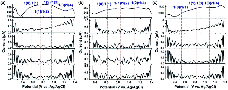 | ||
| Fig. 7 1st to 5th (top to bottom) harmonic components of a FTAC voltammogram (f = 10 Hz, ΔE = 20 mV, and scan rate = 92 mV s−1) of Ru4/PEI-rGO supported with a 1 cm2 carbon cloth in (a) pH 6, (b) pH 4 and (c) pH 8 buffer solutions containing 5 mM HMF. | ||
At an applied voltage of 0.94 V during the electrolysis process, Ru4 stayed at the oxidation state of 1(3) in pH 6 and pH 8 electrolyte solutions but at an oxidation state of 1(2) in pH 4 electrolyte solution (Fig. 7).The yield of furanic products at pH 6 reaches 48.5%, which is 3 times higher than that of the catalytic system (15.9%) at pH 4 (entries 1–3, Table 1). Therefore, it could be concluded that the discrepancy in oxidation states of Ru4 resulted in the different electrocatalytic oxidation performances under three electrolyte conditions, wherein Ru4/PEI-rGO in the oxidation state 1(3) performed the best. Similar results have also been obtained by the electrolysis experiments of Ru4/PEI-rGO at 0.6 V, 0.8 V, and 0.94 V, corresponding to the 1(1), 1(2), and 1(3) oxidation states, respectively. Specifically, a furanic yield of 48.5% achieved at an applied potential of 0.94 V (entry 2, Table 1) was 5.5 times higher than that of the experiment at 0.6 V (8.8%, entry 5, Table 1), substantiating that the electrocatalytic activity largely depends on the proportion of the RuV species in the Ru4/PEI-rGO composite.
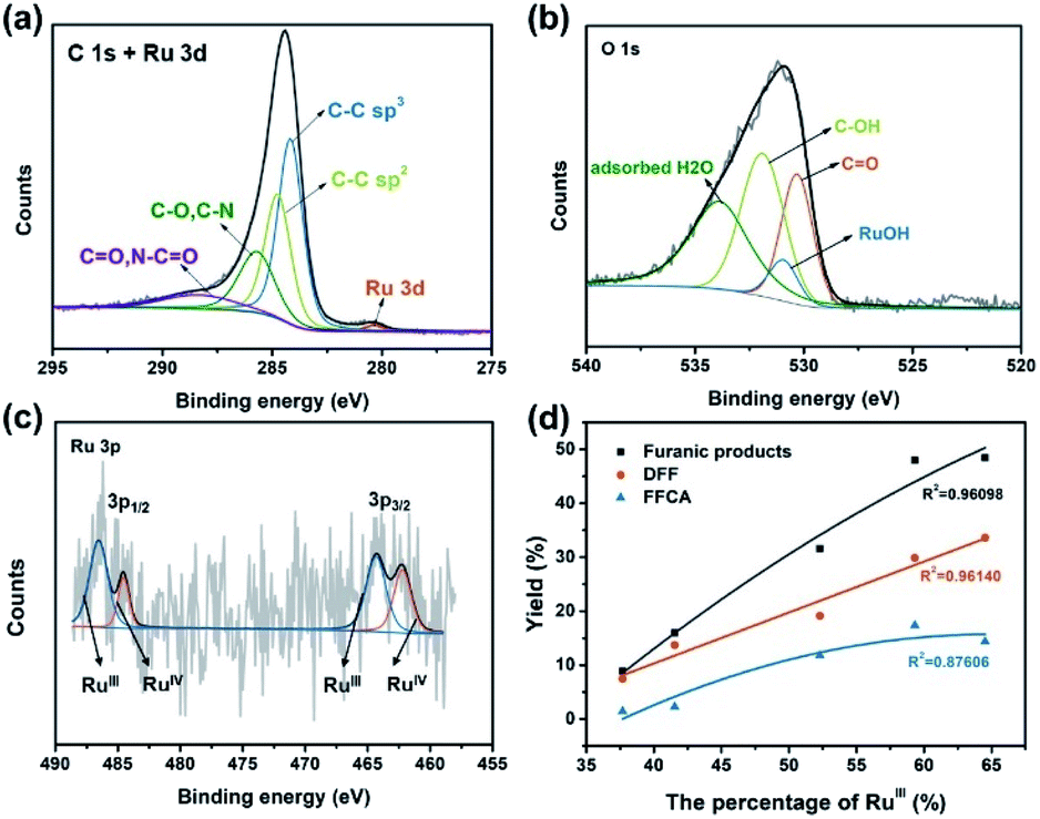
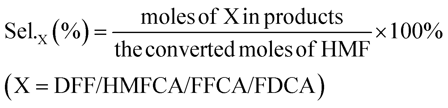
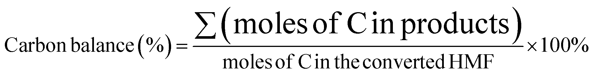
To further understand the chemical environment and electronic properties of Ru4/PEI-rGO, XPS measurements were carried out on Ru4/PEI-rGO after 6 hour electrolysis at 0.94 V in pH 6 electrolyte solution. Compared with that of the fresh catalyst (Fig. S11a†), no obvious changes were observed for the C 1s + Ru 3d XPS spectra (Fig. 8a), indicating good stability of the carbon substrate. The deconvoluted signal of Ru–OH (Fig. S11b†), assigned to the water molecules bounded to RuIV centers,48 significantly decreased after electrolysis (Fig. 8b), proving the active participation of RuIV centers during electrocatalysis. As illustrated by CV and FTAC voltammogram analyses, the initial RuIV centers were first electrooxidized to RuV centers, which further oxidize the HMF substrate during electrocatalysis. The presence of the RuIII species48,49 in the XPS spectra should be attributed to the two-electron reduction of RuV centers by the HMF substrate (Fig. 8c).50 Therefore, the percentage of the RuIII species can indirectly reflect the proportion of the RuV active species in situ electrogenerated during electrocatalysis. The electronic properties of the Ru species after electrocatalysis differ considerably at the different applied voltages and pH values (Fig. S12†). It is shown that the peak area of the RuIII species gradually increases with the increasing applied anodic potential (Fig. 8c, S12a and b†), strongly illustrating the enhanced oxidation of RuIV to the RuV species, which is also consistent with the results of FTAC voltammetry (Fig. 7a). While maintaining a constant applied anodic potential, the higher pH value of the electrolyte solution also results in a larger peak area of the RuIII species (Fig. S12c and d†), also in good agreement with the FTAC voltammetry results (Fig. 7b and c).
 | ||
| Fig. 8 The high resolution (a) C 1s + Ru 3d, (b) O 1s and (c) Ru 3p XPS spectra of Ru4/PEI-rGO upon electrolysis for 6 h at 0.94 V at pH = 6. (d) The plots of the yields of furanic products versus the percentage of the RuIII species. | ||
To intuitively explore the influences of the RuV species on the eletrocatalytic activities, the proportion of the RuIII species determined by the XPS results is thus plotted against the yield of furanic products (entries 1–5, Table 1). As Fig. 8d shows, the yields of furanic products are positively related to the percentage of the RuIII species, indirectly implying that the electrocatalytic activities also show positive correlation to the proportion of the RuV species. Moreover, the yield of DFF is linear to the proportion of the RuIII species, which provides solid proof that RuV centers can effectively oxidize HMF to DFF via a two-electron transfer process with itself being reduced to RuIII, whereas the four-electron transfer process (HMF to FFCA) was limited. When TEMPO was added in the electrocatalytic system, the FFCA yield of 52.4% (entry 6, Table 1) is improved 3.6 times that of the system without TEMPO (entry 2, Table 1); such increased FFCA yield should be attributed to the efficient two-electron oxidation of DFF to FFCA by RuV centers given the fact that TEMPO can promote the oxidation of HMF to DFF (Fig. S13†).
Therefore, based on all above analyses and experimental results (CV, FTAC, and XPS data), it can be concluded that RuV active species in situ generated in the Ru4/PEI-rGO electrocatalyst are responsible for the efficient electrocatalytic oxidation of HMF, and the three-electron oxidized Ru41(3) species performed the best during the electrolysis process. Therefore, the electrocatalytic oxidation mechanism of HMF is proposed as follows; upon electrolysis, in the anodic chamber, the RuIV centers in the Ru4/PEI-rGO composite was first oxidized to the three-electron oxidation state 1(3) that can catalyze the conversion of HMF to furanic products with itself being transformed into the RuIII species. In the meantime, the released protons during these processes are further subjected to reduction to hydrogen in the cathodic chamber, accomplishing a complete valorization cycle of HMF to furanic products and hydrogen.
To investigate the stability, long-term bulk electrolysis of Ru4/PEI-rGO was conducted (Fig. 9a and S14†). With prolonging electrolysis, the conversion of HMF gradually increased and reached 71.4% after 12 hours. No obvious changes were observed in the SEM and TEM images (Fig. S15†) of Ru4/PEI-rGO after the long-term reaction compared to that of the fresh Ru4/PEI-rGO composite (Fig. S2†). The FT-IR spectra were further used to determine the possible changes of the composite after long-term electrolysis. As shown in Fig. 9b, the characteristic bands of WO, W–O–W, and Ru–O–Ru of Ru4 POM still remain after 12 hour long-term electrolysis, revealing the intact skeleton structure of Ru4. It is worth mentioning that the slight red shift of characteristic bands could be attributed to the enhanced electronic interaction between Ru4 and the PEI-rGO support. In addition, to test the heterogeneity of the Ru4/PEI-rGO electrocatalyst, the amount of Ru in the post-reaction solution after 12 hour electrolysis was quantified to be 0.04 ppm by the ICP test, indicating the stable electrostatic immobilization of Ru4 POM onto the PEI-rGO surface. These results strongly confirmed that Ru4 POM possessed good stability during the electrolysis process in the near-neutral electrolyte.
 | ||
| Fig. 9 (a) The long-term bulk electrolysis of Ru4/PEI-rGO at an applied voltage of 0.94 V in pH 6 electrolyte solution. (b) FT-IR spectra of Ru4 and Ru4/PEI-rGO before and after long-term electrolysis. | ||
Conclusions
In conclusion, we have reported the preparation of a Ru4/PEI-rGO electrocatalyst through electrostatic integration of negatively-charged Ru4 POM and positively-charged PEI modified rGO. The resulting Ru4/PEI-rGO electrocatalyst can effectively catalyze the oxidation of HMF into value-added furanic products simultaneously coupled with hydrogen production. We have further optimized the reaction parameters during the preparation of catalysts and the electrocatalytic process, including the amount of PEI, the content of Ru4 POM, the loading quantity of the composite electrocatalyst onto carbon cloth, the reaction atmosphere, etc. Moreover, the influences of a commonly-used additive, TEMPO, on the electrocatalytic activity were also investigated, which not only significantly promoted the electrooxidation of HMF but also regulated the product distribution. Electrochemical techniques (CV, LSV and FTAC) and XPS analyses were employed to disclose the catalytically active species and further get insight into the electrocatalytic oxidation mechanism of HMF as follows; upon electrolysis, in the anodic chamber, the RuIV centers in the Ru4/PEI-rGO composite was first oxidized to the three-electron oxidation state 1(3) that can catalyze the conversion of HMF to furanic products with itself being transformed into the RuIII species. In the meantime, the released protons during these processes are further subjected to reduction to hydrogen in the cathodic chamber, accomplishing a complete valorization cycle of HMF to furanic products and hydrogen.Experimental
Materials and methods
All starting chemicals and solvents for synthesis, characterization, and electrochemical tests were purchased from commercial sources without further purification unless otherwise noted. Rb8K2[Ru4(μ-O)4(μ-OH)2(H2O)4(γ-SiW10O36)2]·25H2O (Ru4) was synthesized according to a method reported in the literature. TG analysis was performed by using a Mettler Toledo TGA/DSC 1100 thermal analyzer with a rate of 10 °C min−1 in an air atmosphere. FT-IR was performed on a Bruker Tensor II with KBr pellets. Scanning electron microscopy (SEM) images and EDX element analysis images were collected on a ZEISS Supra55. HRTEM, HAADF-STEM analysis and element mapping analysis images were collected with an FEI Talos F200X. The zeta potential was obtained by using a NICOMP Z3000 NANO ZLS. The XPS data were collected by using a PHI QUANTERA-II SXM (ULVAC-PHI, Japan) with Al Kα. Inductively coupled plasma optical emission spectrometry (ICP-OES) data were obtained with an Agilent ICPOES730.Synthetic procedures
Electrochemical measurements
Electrochemical measurements were carried out with a CHI 660E potentiostat at room temperature, using an airtight H-type electrochemical cell with the carbon cloth as the working electrode, the Pt sheet as the counter electrode, and a Ag/AgCl electrode as the reference electrode. The working electrode was prepared as the following procedure; catalyst ink was first prepared by sonicating a mixture of 5 mg Ru4/PEI-rGO catalyst and 1 mL Nafion ethanol solution (0.25 wt%) for 30 min. Next, the clean and pre-treated carbon cloth (1 × 1 cm2) was evenly coated with 100 μL catalyst ink, followed by drying under an infrared lamp. LSV and CV measurements were conducted in sequence for the electrocatalysts. 0.5 M HAc/NaAc buffer solution containing 5 mM HMF was used as the electrolyte solution. EIS measurements were performed in 5 mM HMF at 0.94 V vs. Ag/AgCl. Before testing, the cathodic chamber was purged with CH4/Ar (20%, volume ratio) gas until no air is detected on a gas chromatography (GC) system, where CH4 was used as an internal standard. Under the applied voltage, HMF was gradually oxidized at the anode chamber, where the liquid products were analysed on a HPLC system equipped with a Shim-pack GIST C18 column (5 μM, 4.6 × 250 mm) and a UV detector. Methanol and ammonium acetate aqueous solution (5 mM) with a volume ratio of 30:70 were used as the mobile phase with a flow rate of 0.3 mL min−1. The detection wavelength is 270 nm. The hydrogen evolution in the cathode chamber was determined on a GC system equipped with a 5A molecular sieve packed column (60/80 mesh, 2 m × 3 mm) and a TCD detector.
FTAC voltammetric measurements were performed with a home-built apparatus, using an applied sine wave perturbation (amplitude 20 mV and frequency 10 Hz) superimposed onto the dc ramp.
HMF conversion, DFF/HMFCA/FFCA/FDCA selectivity, carbon balance and Faraday efficiency (FE) were calculated according to eqn (1)–(4).
 | (1) |
 | (2) |
 | (3) |
 | (4) |
485 C mol−1).
Author contributions
Hui Zhou: methodology, data curation, formal analysis, investigation, and writing – original draft preparation. Xing Xin and Manzhou Chi: discussions. Tinglu Song: XPS measurement. Yuanyuan Dong and Hongjin Lv: funding acquisition, project administration, conceptualization, supervision, validation, and writing – reviewing and editing.Conflicts of interest
There are no conflicts to declare.Acknowledgements
We gratefully acknowledge the financial support from the National Natural Science Foundation of China (21706080, 21871025, 21831001 and 12074017), the Recruitment Program of Global Experts (Young Talents) and BIT Excellent Young Scholars Research Fund and the start-up funding of BIT; the instrumental support from the Analysis and Testing Center of Beijing Institute of Technology is also highly appreciated.References
- M. Zhang, Y. Liu, B. Liu, Z. Chen, H. Xu and K. Yan, ACS Catal., 2020, 10, 5179–5189 CrossRef CAS.
- W. Liu, W. You, Y. Gong and Y. Deng, Energy Environ. Sci., 2020, 13, 917–927 RSC.
- W. Liu, Y. Cui, X. Du, Z. Zhang, Z. Chao and Y. Deng, Energy Environ. Sci., 2016, 9, 467–472 RSC.
- H. Zhao, D. Lu, J. Wang, W. Tu, D. Wu, S. W. Koh, P. Gao, Z. J. Xu, S. Deng, Y. Zhou, B. You and H. Li, Nat. Commun., 2021, 12, 2008 CrossRef CAS PubMed.
- J. Iglesias, I. Martínez-Salazar, P. Maireles-Torres, D. Martin Alonso, R. Mariscal and M. López Granados, Chem. Soc. Rev., 2020, 49, 5704–5771 RSC.
- B. You, N. Jiang, X. Liu and Y. Sun, Angew. Chem., Int. Ed., 2016, 55, 9913–9917 CrossRef CAS PubMed.
- X. Deng, G.-Y. Xu, Y.-J. Zhang, L. Wang, J. Zhang, J.-F. Li, X.-Z. Fu and J.-L. Luo, Angew. Chem., Int. Ed., 2021, 60, 20535–20542 CrossRef CAS PubMed.
- R. Latsuzbaia, R. Bisselink, A. Anastasopol, H. van der Meer, R. van Heck, M. S. Yagüe, M. Zijlstra, M. Roelands, M. Crockatt, E. Goetheer and E. Giling, J. Appl. Electrochem., 2018, 48, 611–626 CrossRef CAS.
- M. Park, M. Gu and B.-S. Kim, ACS Nano, 2020, 14, 6812–6822 CrossRef CAS PubMed.
- S. Kar, Q.-Q. Zhou, Y. Ben-David and D. Milstein, J. Am. Chem. Soc., 2022, 144, 1288–1295 CrossRef CAS PubMed.
- G. Grabowski, J. Lewkowski and R. Skowroński, Electrochim. Acta, 1991, 36, 1995 CrossRef CAS.
- A. R. Poerwoprajitno, L. Gloag, J. Watt, S. Cychy, S. Cheong, P. V. Kumar, T. M. Benedetti, C. Deng, K.-H. Wu, C. E. Marjo, D. L. Huber, M. Muhler, J. J. Gooding, W. Schuhmann, D.-W. Wang and R. D. Tilley, Angew. Chem., Int. Ed., 2020, 59, 15487–15491 CrossRef CAS PubMed.
- S. Barwe, J. Weidner, S. Cychy, D. M. Morales, S. Dieckhöfer, D. Hiltrop, J. Masa, M. Muhler and W. Schuhmann, Angew. Chem., Int. Ed., 2018, 57, 11460–11464 CrossRef CAS PubMed.
- L. Gao, Y. Bao, S. Gan, Z. Sun, Z. Song, D. Han, F. Li and L. Niu, ChemSusChem, 2018, 11, 2547–2553 CrossRef CAS PubMed.
- H. Chen, J. Wang, Y. Yao, Z. Zhang, Z. Yang, J. Li, K. Chen, X. Lu, P. Ouyang and J. Fu, ChemElectroChem, 2019, 6, 5797–5801 CrossRef CAS.
- H. G. Cha and K.-S. Choi, Nat. Chem., 2015, 7, 328–333 CrossRef CAS PubMed.
- Q. Qin, T. Heil, J. Schmidt, M. Schmallegger, G. Gescheidt, M. Antonietti and M. Oschatz, ACS Appl. Energy Mater., 2019, 2, 8359–8365 CrossRef CAS.
- A. Corma, S. Iborra and A. Velty, Chem. Rev., 2007, 107, 2411–2502 CrossRef CAS PubMed.
- T. Cao, M. Wu, V. V. Ordomsky, X. Xin, H. Wang, P. Métivier and M. Pera-Titus, ChemSusChem, 2017, 10, 4851–4854 CrossRef CAS PubMed.
- N. Li, J. Liu, B.-X. Dong and Y.-Q. Lan, Angew. Chem., Int. Ed., 2020, 59, 20779–20793 CrossRef CAS PubMed.
- D. Shi, R. Zheng, C.-S. Liu, D.-M. Chen, J. Zhao and M. Du, Inorg. Chem., 2019, 58, 7229–7235 CrossRef CAS PubMed.
- S.-B. Yu, Q. Qi, B. Yang, H. Wang, D.-W. Zhang, Y. Liu and Z.-T. Li, Small, 2018, 14, 1801037 CrossRef PubMed.
- H. Lv, W. Guo, K. Wu, Z. Chen, J. Bacsa, D. G. Musaev, Y. V. Geletii, S. M. Lauinger, T. Lian and C. L. Hill, J. Am. Chem. Soc., 2014, 136, 14015–14018 CrossRef CAS PubMed.
- J. Zhang, M. Zhang, Y. Dong, C. Bai, Y. Feng, L. Jiao and H. Lv, Nano Res., 2022, 15, 1347–1354 CrossRef CAS.
- Q. Yin, J. M. Tan, C. Besson, Y. V. Geletii, D. G. Musaev, A. E. Kuznetsov, Z. Luo, K. I. Hardcastle and C. L. Hill, Science, 2010, 328, 342–345 CrossRef CAS PubMed.
- B. Chakraborty, G. Gan-Or, Y. Duan, M. Raula and I. A. Weinstock, Angew. Chem., Int. Ed., 2019, 58, 6584–6589 CrossRef CAS PubMed.
- Y. Choi, D. Jeon, Y. Choi, J. Ryu and B.-S. Kim, ACS Appl. Mater. Interfaces, 2018, 10, 13434–13441 CrossRef CAS PubMed.
- S.-L. Xie, J. Liu, L.-Z. Dong, S.-L. Li, Y.-Q. Lan and Z.-M. Su, Chem. Sci., 2019, 10, 185–190 RSC.
- E. Haviv, L. J. W. Shimon and R. Neumann, Chem.–Eur. J., 2017, 23, 92–95 CrossRef CAS PubMed.
- S.-X. Guo, F. Li, L. Chen, D. R. MacFarlane and J. Zhang, ACS Appl. Mater. Interfaces, 2018, 10, 12690–12697 CrossRef CAS PubMed.
- L. Ni, H. Li, H. Xu, C. Shen, R. Liu, J. Xie, F. Zhang, C. Chen, H. Zhao, T. Zuo and G. Diao, ACS Appl. Mater. Interfaces, 2019, 11, 38708–38718 CrossRef CAS PubMed.
- T. Zhang, A. Solé-Daura, H. Fouilloux, J. M. Poblet, A. Proust, J. J. Carbó and G. Guillemot, ChemCatChem, 2021, 13, 1220–1229 CrossRef CAS.
- M. Zhao, X.-W. Zhang and C.-D. Wu, ACS Catal., 2017, 7, 6573–6580 CrossRef CAS.
- X.-L. Hao, Y.-Y. Ma, H.-Y. Zang, Y.-H. Wang, Y.-G. Li and E.-B. Wang, Chem.–Eur. J., 2015, 21, 3778–3784 CrossRef CAS PubMed.
- G. Chen, Y. Zhou, Z. Long, X. Wang, J. Li and J. Wang, ACS Appl. Mater. Interfaces, 2014, 6, 4438–4446 CrossRef CAS PubMed.
- E. Nikbakht, B. Yadollahi and M. R. Farsani, Inorg. Chem. Commun., 2015, 55, 135–138 CrossRef CAS.
- Z. Li, J. Zhang, X. Jing, J. Dong, H. Liu, H. Lv, Y. Chi and C. Hu, J. Mater. Chem. A, 2021, 9, 6152–6159 RSC.
- J. Lu, Y. Li, S. Li and S. P. Jiang, Sci. Rep., 2016, 6, 21530 CrossRef CAS PubMed.
- W. Tong, Y. Zhang, Q. Zhang, X. Luan, Y. Duan, S. Pan, F. Lv and Q. An, Carbon, 2015, 94, 590–598 CrossRef CAS.
- R. Wang, L. Wu, D. Zhuo, Z. Wang and T. Y. Tsai, Nanoscale Res. Lett., 2018, 13, 351 CrossRef PubMed.
- P. Gobbo, L. Tian, B. V. V. S. Pavan Kumar, S. Turvey, M. Cattelan, A. J. Patil, M. Carraro, M. Bonchio and S. Mann, Nat. Commun., 2020, 11, 41 CrossRef CAS PubMed.
- A. Sartorel, M. Carraro, G. Scorrano, R. D. Zorzi, S. Geremia, N. D. McDaniel, S. Bernhard and M. Bonchio, J. Am. Chem. Soc., 2008, 130, 5006–5007 CrossRef CAS PubMed.
- Y. Liu, S.-F. Zhao, S.-X. Guo, A. M. Bond, J. Zhang, G. Zhu, C. L. Hill and Y. V. Geletii, J. Am. Chem. Soc., 2016, 138, 2617–2628 CrossRef CAS PubMed.
- H. Lv, Z. Li, M. Zhang and X. Xin, ChemCatChem, 2021, 13, 1389–1395 CrossRef.
- M. Zhang, C. Chen, W. Ma and J. Zhao, Angew. Chem., Int. Ed., 2008, 47, 9730–9733 CrossRef CAS PubMed.
- C.-Y. Lee, S.-X. Guo, A. F. Murphy, T. McCormac, J. Zhang, A. M. Bond, G. Zhu, C. L. Hill and Y. V. Geletii, Inorg. Chem., 2012, 51, 11521–11532 CrossRef CAS PubMed.
- Y. Liu, S.-X. Guo, A. M. Bond, J. Zhang, Y. V. Geletii and C. L. Hill, Inorg. Chem., 2013, 52, 11986–11996 CrossRef CAS PubMed.
- D. J. Morgan, Surf. Interface Anal., 2015, 47, 1072–1079 CrossRef CAS.
- W. Wang, S. Guo, I. Lee, K. Ahmed, J. Zhong, Z. Favors, F. Zaera, M. Ozkan and C. S. Ozkan, Sci. Rep., 2014, 4, 4452 CrossRef PubMed.
- R. Ge, Y. Wang, Z. Li, M. Xu, S.-M. Xu, H. Zhou, K. Ji, F. Chen, J. Zhou and H. Duan, Angew. Chem., Int. Ed., 2022, 61, e202200211 CAS.
- Y. V. Geletii, B. Botar, P. Kögerler, D. A. Hillesheim, D. G. Musaev and C. L. Hill, Angew. Chem., Int. Ed., 2008, 47, 3896–3899 CrossRef CAS PubMed.
- Y. Dong, Y. Deng, J. Zeng, H. Song and S. Liao, J. Mater. Chem. A, 2017, 5, 5829–5837 RSC.
Footnote |
| † Electronic supplementary information (ESI) available. See https://doi.org/10.1039/d2ta02148j |
| This journal is © The Royal Society of Chemistry 2022 |