
Multivalent cationic and anionic mixed redox of an Sb2S3 cathode toward high-capacity aluminum ion batteries†
Tongge
Li‡
 a,
Tonghui
Cai‡
*b,
Haoyu
Hu
b,
Xuejin
Li
b,
Dandan
Wang
b,
Yu
Zhang
a,
Yongpeng
Cui
b,
Lianming
Zhao
b,
Wei
Xing
b and
Zifeng
Yan
*a
a,
Tonghui
Cai‡
*b,
Haoyu
Hu
b,
Xuejin
Li
b,
Dandan
Wang
b,
Yu
Zhang
a,
Yongpeng
Cui
b,
Lianming
Zhao
b,
Wei
Xing
b and
Zifeng
Yan
*a
aState Key Laboratory of Heavy Oil Processing, College of Chemistry and Chemical Engineering, China University of Petroleum, Qingdao 266580, China. E-mail: zfyancat@upc.edu.cn
bSchool of Materials Science and Engineering, China University of Petroleum, Qingdao 266580, China. E-mail: caitonghui@upc.edu.cn
First published on 21st April 2022
Abstract
The conventional cationic redox centers of transition-metal-based cathodes are reaching their theoretical capacity limit, which cannot match the ultra-high specific capacity contributed by the three-electron transfer reaction of an Al anode (2980 mA h g−1, 8056 mA h cm−3), severely restraining the development of high-energy rechargeable Al-ion batteries (RAIBs). In this work, we propose the multivalent cationic and anionic mixed redox chemistry of Sb2S3 as a promising way out of this problem. The energy storage is induced by the cumulative Sb-related cationic (Sb(+3) ⇔ Sb(+5)) and S-related anionic (S(−2) ⇔ S(0)) mixed 10-electron transfer reversible redox reaction during the charge/discharge process, which has been elucidated here by extensive electrochemical measurements and characterizations. Furthermore, excellent electrochemical performances are realized due to the carbon-based interlayer effectively blocking the charging products of the Sb-based cationic cluster (SbCl4+), by a dual defense mechanism that integrates the physical barrier of the porous structure and the powerful chemical adsorption ability of the oxygen groups. The Sb2S3 cathode could deliver a discharge specific capacity of 756 mA h g−1 at 100 mA g−1. The finding is that the joint multivalent cationic and anionic redox chemistry proposed in this work opens up new opportunities for designing high-performance electrodes for advanced rechargeable batteries.
Introduction
The high reserves of the metal Al, and its high safety, low cost, and non-toxicity have made the aluminum-ion battery (AIB) a competitive metal-ion battery system. Significantly, the reversible three-electron transfer reaction of the Al anode can deliver an ultra-high specific capacity of 2980 mA h g−1 and 8056 mA h cm−3,1 promoting AIBs as a primary candidate for the next-generation energy storage system. Nonetheless, the energy density and sustainability of AIBs until now are still not comparable to Li-ion batteries, with the lack of suitable multi-electron-based cathodes, to match the highly reversible three-electron transfer reaction of the Al anode, being a major obstacle. Therefore, an intense research effort has been spurred into action for the discovery of novel cathode materials for AIBs with a multi-electron transfer reaction, large capacity, and long cycle life.Among the cathode candidates for AIBs considered at present, transition-metal-sulfide (TMS) cathodes are the most attractive, owing to their multi-electron transfer reactions.2 But, since the advent of AIBs, the multi-electron transfer reaction of these TMS has been considered/proved exclusively based on cationic redox electrochemistry. Unfortunately, without the contribution of S-based anionic redox, the average number of electrons transferred per element based solely on the cationic redox of these cathodes is relatively small,3–5 thus leading to insufficient theoretical capacity for real-world implementation. Therefore, introducing a multivalent cationic and S-based anionic mixed redox is an effective approach to boost the specific capacity and energy density via accessing the charge transfer from all the elements of TMS, but it also faces huge challenges.
Here, we report a novel one-dimensional nanorod-like Sb2S3 material as a cathode for high-capacity RAIBs for the first time. Unlike previously reported TMS cathodes, where energy storage is induced by the redox reaction of the cations, the mechanism from which the high capacity is achieved lies in the reversible redox of the S-related anions in addition to the metal Sb-related cations of Sb2S3. Based on the cumulative Sb-related cationic (Sb(+3) ⇔ Sb(+5)) and S-related anionic (S(−2) ⇔ S(0)) mixed reversible redox processes, the Sb2S3 cathode can deliver a mixed 10-electron transfer reaction, holding a surprising theoretical capacity of 789 mA h g−1. Furthermore, a graphene aerogel interlayer as a preventive measure for tackling the possible shuttle effect of the soluble ion-based products was proved to be a sensible option. Density functional theory (DFT) calculations showed that reduced graphene oxide with oxygen-containing functional groups could powerfully chemically adsorb the cationic clusters of SbCl4+. As a result, this novel Sb2S3 cathode delivers an initial discharge specific capacity of 756 mA h g−1 at 100 mA g−1, nearing its theoretical limit. Even at a high current density of 1000 mA g−1, the discharge specific capacity is as high as ca. 500 mA h g−1, remaining at 363 mA h g−1 after 220 cycles. Considering both the discharge capacity and rate performance, the cathode prepared herein surpasses all the transition-metal-based cathode materials reported to date.
Results and discussion
Preparation and morphology of Sb2S3 nanorods
The synthesis process of Sb2S3 nanorods is shown in Fig. 1a, and detailed experiments can be seen in the ESI.† Antimony trichloride was hydrolyzed to produce antimony oxychloride, which was vulcanized by a solvothermal reaction to produce rod-shaped Sb2S3. Fig. 1b shows the XRD pattern of the synthesized Sb2S3. All the characteristic peaks match the orthorhombic Sb2S3 phase (JCPDS card no. 00-006-0474). The morphology of Sb2S3 was characterized by SEM and TEM (Fig. 1c–e). Fig. 1c shows that the synthesized Sb2S3 nanorods are aggregated from multiple thinner nanorods with a diameter of ca. 100 nm. The TEM image clearly shows that the structure of Sb2S3 is very uniform. It can be seen from the electron diffraction pattern of the selected area (Fig. 1e) that the synthesized Sb2S3 is in a single crystal state, and the lattice spacing of the (110) crystal plane is 0.8 nm.6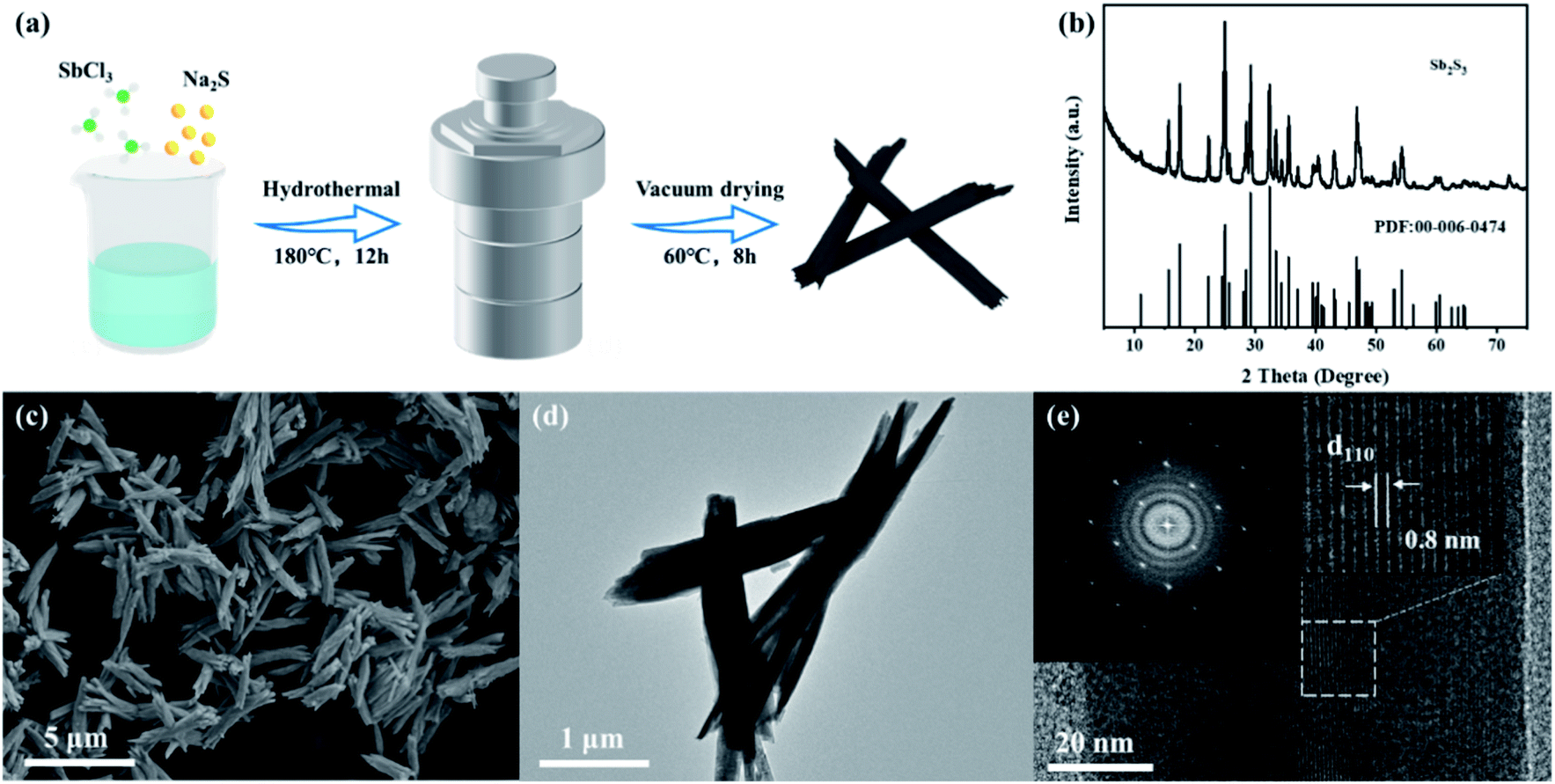 | ||
| Fig. 1 (a) Schematic diagram of the preparation process of Sb2S3 nanorods. (b) XRD pattern; (c) SEM; (d) TEM image; (e) HR-TEM image and the selected-area electron diffraction pattern of Sb2S3. | ||
Electrochemical performance of the Sb2S3 cathode
Sb2S3 with a graphene aerogel interlayer was assembled in a Swagelok-type battery (Fig. S1†) to evaluate the electrochemical performance of Sb2S3 as an RAIB battery cathode material. As shown in Fig. 2a, the CV curve of the Sb2S3 cathode has two obvious oxidation peaks in the voltage range of 0.8 to 1.9 V and the corresponding reduction peaks appear in the voltage range of 0.9 to 0.3 V. In order to further understand the kinetics of the Sb2S3 cathode, the relation between the peak current and scan rate can be expressed as i = avb, where i is the response current (mA) and v is the scan rate (mV s−1); a and b are adjustable values. A b value of 0.5 generally indicates a diffusion-controlled process, while a value of 1.0 suggests that the reaction is a surface charge transfer process.7,8 By fitting the redox peaks at different scan rates it was found that the slopes of the fitting curves for different redox peaks were 0.96, 0.92, 0.90, and 0.95, respectively, indicating an interplay between surface- and diffusion-controlled reactions, but predominantly a surface-driven pseudo-capacitive action (Fig. 2c). The calculated contribution of pseudo-capacitance and ion diffusion to battery capacity was calculated according to the formula i(V) = k1v + k2v1/2, where i(V) is the total current response at a given potential V, and k1 and k2 are the capacitive and diffusion contribution, respectively. As shown in Fig. 2b, the pseudo-capacitance contribution to the total charge storage area curves at a scan rate of 1.0 mV s−1 was 94.9%, indicating that the Sb2S3 cathode exhibits almost complete pseudo-capacitive properties.9,10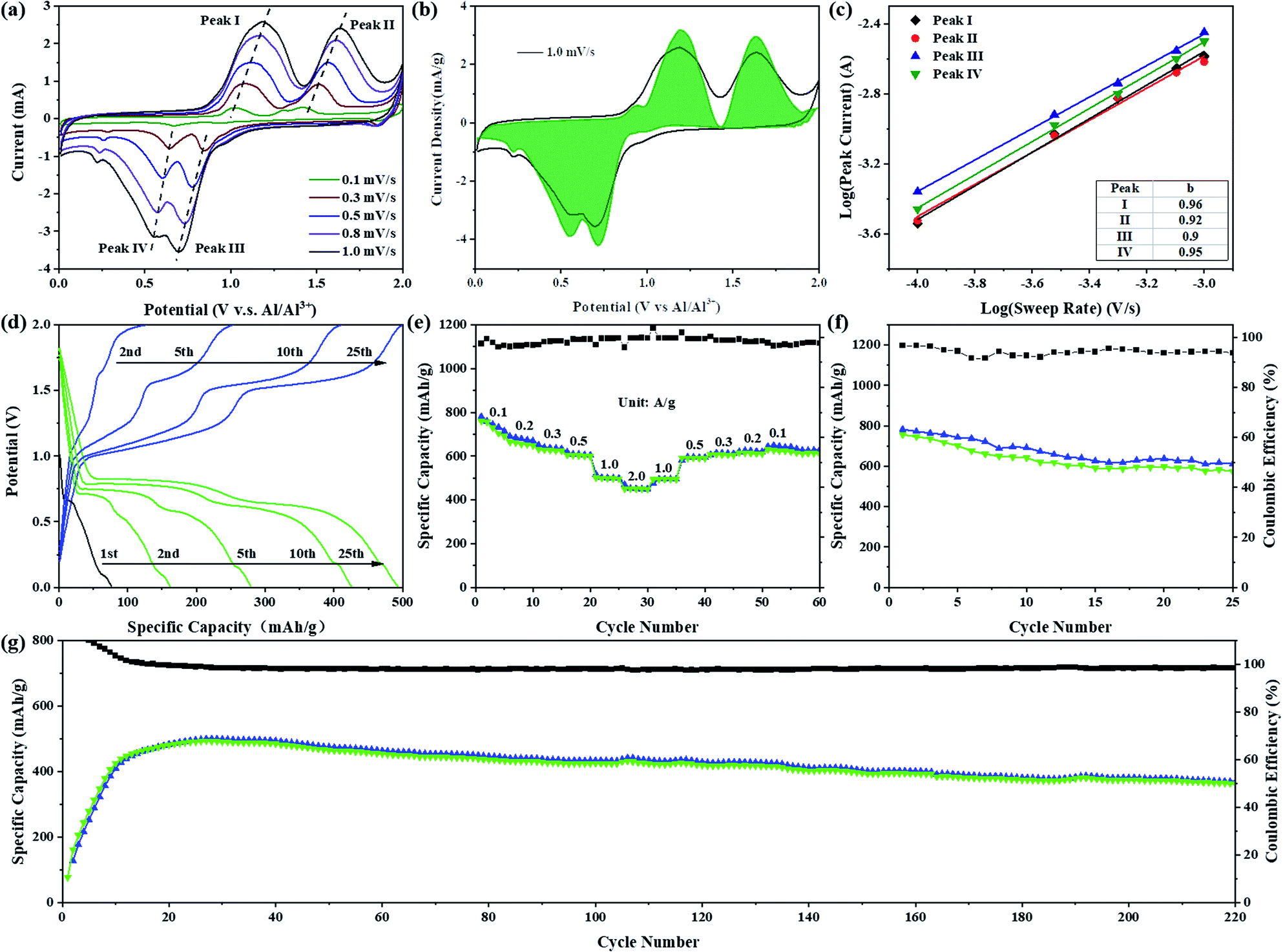 | ||
| Fig. 2 Electrochemical performance of Sb2S3: (a) CV curves at different scan rates. (b) Comparison graph of pseudo-capacitance contribution and CV curve at a scan rate of 1.0 mV s−1. (c) The log(i)–log(v) plots of peaks and their linear fitting results. (d) The galvanostatic charge/discharge curve at 1000 mA g−1. (e) The rate performance at different current densities. Cycle performance curves at (f) 100 mA g−1 and (g) 1000 mA g−1. Notes: in (e) and (f) share the same y-axis of coulombic efficiency. | ||
Fig. 2d shows the galvanostatic charge/discharge curve at a high current density of 1000 mA g−1. The assembled battery was discharged first, and the initial discharge capacity was 75 mA h g−1. After nearly 20 cycles of activation, the charge–discharge specific capacity reached a stable level of 489 mA h g−1. Two charging plateaus at ca. 1.15 and 1.60 V, and the corresponding discharge plateaus at ca. 0.65 and 0.80 V were observed, in full agreement with the CV curve. While, at a small current density of 100 mA g−1, we compared two charging protocols: charge-first, and discharge-first (Fig. S2†). The initial discharge capacity of discharge-first was small, only 140 mA h g−1, which is mainly contributed by the formation of an SEI film, GA interlayer and conductive carbon black, but the following charging curve of the two charging protocols showed almost no difference in capacity or voltage plateau. After one cycle of activation, the capacity and voltage plateau of the charge–discharge curve tended to be stable, and the discharge specific capacity could reach 756 mA h g−1 with a cell-level energy density of 80 W h kg−1 (Fig. S3a†).11,12 Furthermore, on the charging curve at this current density, a third-stage charging plateau appeared in the voltage range 1.8–2.0 V, which can be judged to be the oxidation of S (S0 → Sx+).11 However, no corresponding high-potential discharge plateau was observed on the discharge curve, which resulted in a low coulombic efficiency (∼95%). To find a more suitable voltage window, cycling performance tests were carried out in different voltage ranges at 1000 mA g−1 (Fig. S4 and S5†). In the voltage range 0.2–1.8 V, the capacity stabilized at about 225 mA h g−1 after 50 cycles. After increasing the cut-off voltage of charging to 2.0 V, the capacity rapidly increased to about 500 mA h g−1, which is due to the increasing cut-off voltage being able to make the reaction more sufficient. The discharge potentials were adjusted to 0.1 V and 0.01 V, respectively, and the capacities were comparable, but the cycle decay rate of the battery was lower in the working region of 0.01–2.0 V. The capacity was 318 mA h g−1 after 120 cycles in the working range 0.2–2.0 V. Fig. 2e shows the rate performance curves at different current densities. The discharge specific capacities were 660, 630, 604, and 450 mA h g−1 at current densities of 200, 300, 500, and 2000 mA g−1, respectively. After gradually reducing the current density to 100 mA g−1, the specific discharge capacity could be maintained at 615 mA h g−1. At a large current density of 1000 mA g−1, the capacity of the battery required several cycles of activation to be fully developed, and was maintained at 363 mA h g−1 after 220 cycles with coulombic efficiencies much closer to 100% (Fig. 2g). Fig. S3c† demonstrates the cycling performance of the Sb2S3 electrode with higher loadings. The capacities remained at 311, 260 and 175 mA h g−1 after 200 cycles at high loadings of 2.6, 4.5 and 7.5 mg, respectively. Compared to reported transition-metal-based cathodes (Table S1†), the discharge capacity and the rate performance of Sb2S3 are among those of the best cathode materials reported for AIBs. It is remarkable, however, that the reversible charge specific capacity of the Sb2S3 cathode (756 mA h g−1) is much higher than the theoretical specific capacity (473 mA h g−1) of the only Sb-based cationic redox reaction from Sb(+3) to Sb(0). In view of the above analysis of electrochemical properties, a bold hypothesis emerges naturally that the S-based anionic oxidation reaction also contributes reversible charge specific capacity to the Sb2S3 cathode during the charging process. Furthermore, similar cathodic peaks in the range of 1.4 to 1.9 V (Fig. S6†) were observed by comparing the CV curves of Sb2S3 and elemental sulfur (oxidized from S(−2) to S(0)),13,14 which further echoed our hypothesis of the S-based anionic reaction in the Sb2S3 cathode. This navigated us to pursue the possible energy storage mechanism of the cationic and anionic mixed redox reaction in the Sb2S3 cathode, which seemed promising.
Characterization of energy storage mechanism
To explore the possible cationic and anionic mixed redox based energy storage mechanism of the Sb2S3 cathode in RAIBs, TEM, in situ XRD, ex situ XPS, and ex situ Raman measurements were conducted herein to identify the electrode components and structures in different charge/discharge stages. Comparing the TEM image and the corresponding element mapping images of the Sb2S3 cathode in the initial state and the fully charged/discharged states (Fig. S7 and S8†), it can be shown that the Sb2S3 cathode underwent a phase change reaction during the charging process. To prove that, in situ XRD (Fig. S9†) was conducted to monitor the structural changes of the Sb2S3 cathode during the charging and discharging process. Compared with the XRD pattern of pure Sb2S3 powder shown in Fig. 1b, the relative strength of the characteristic peak for the Sb2S3 cathode, collected by an X-ray penetrating Be current collector, has changed to a certain extent, but there is no change in the peak position. Fig. S10† shows that the peaks of the Be current collector exist at the angles of 45.81, 50.93, 52.79, and 70.89°, and the peak intensity is much higher than that of the electrode material.15 In order to improve the sensitivity of in situ XRD detection, the range of signal acquisition was set at 5–50°. Fig. 3a shows the structural changes of the Sb2S3 during the first discharge and the second complete charge/discharge cycle. The main characteristic peaks of Sb2S3 exist at 22.30, 25.04, 28.50, 29.26, and 35.52°. During the initial discharge process, the intensity of the monitored Sb2S3 peak did not change, and no new peaks appeared, which indicated that Sb2S3 was not reduced into crystal Sb during the first discharge process.16 Then, during the charging process, the intensity of the characteristic peak of Sb2S3 gradually weakened, which indicates that the Sb2S3 cathode was consumed by a phase change reaction. In addition, no deviation of the characteristic peaks of the cathode was observed, and no new peaks appeared, so it can be speculated that the energy storage mechanism is different from the conventional intercalation conversion mechanism.3,17–19 During the discharge process, the intensity of these characteristic peaks for Sb2S3 gradually returned to the initial state completely, and no new peaks were detected, indicating that the charging product could be reduced sufficiently thus leading to the regeneration of crystal Sb2S3. This fully demonstrates the reversibility of the battery reaction.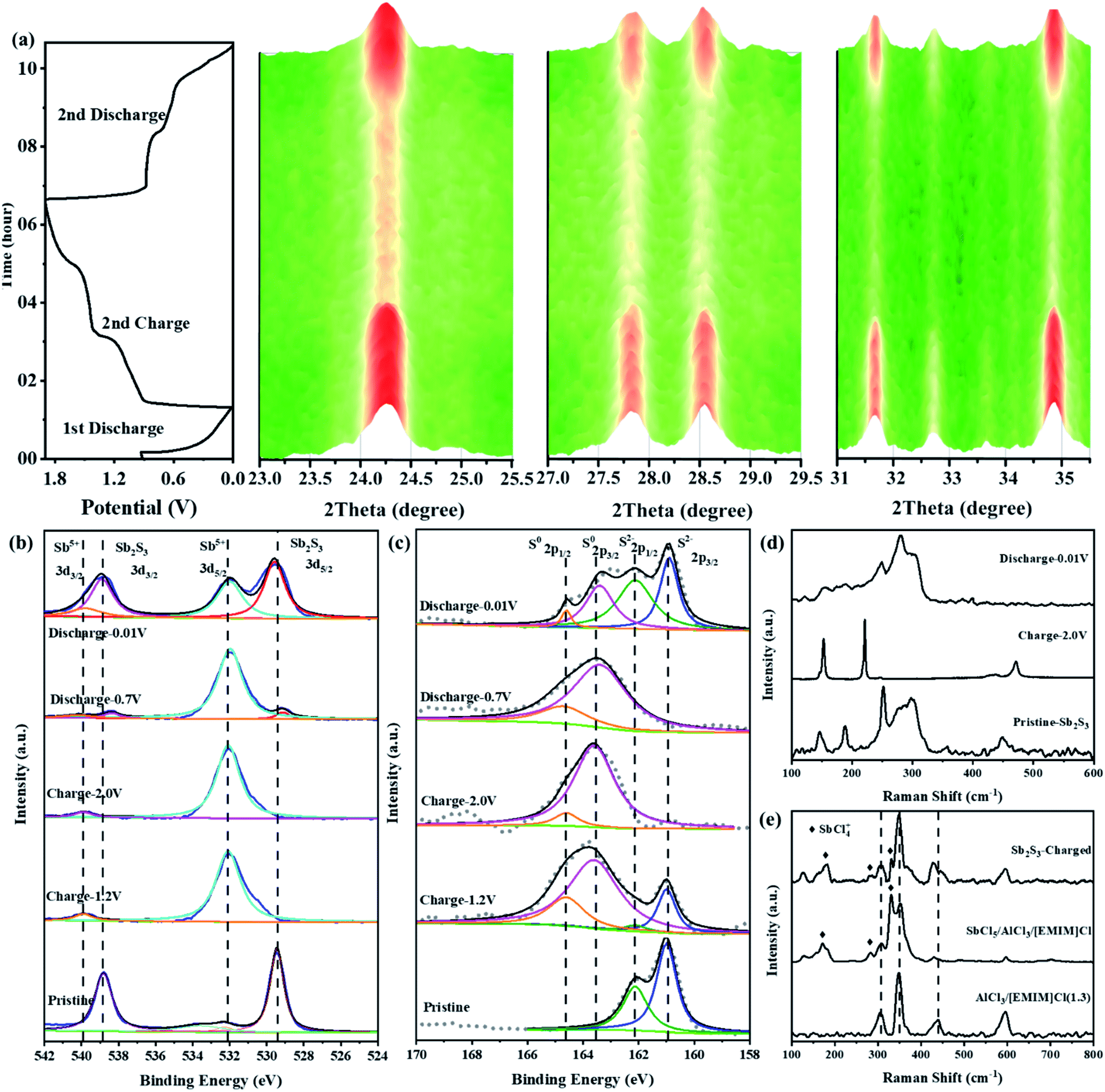 | ||
| Fig. 3 (a) In situ XRD patterns of Sb2S3 electrodes in different charge/discharge states. (b and c) Ex situ XPS spectra of Sb 3d and S 2p of Sb2S3 electrodes in different charge/discharge states. (d) Ex situ Raman spectra of Sb2S3 electrodes in different charge/discharge states. (e) Raman spectra of the electrolyte after fully charged sate, pure electrolyte, and electrolyte with SbCl5. | ||
Fig. 3b and c show the ex situ XPS spectra of Sb 3d and S 2p of the Sb2S3 electrodes in different charge/discharge states. As shown in Fig. 3b, the Sb spectrum of pristine Sb2S3 has two characteristic peaks at 529.48 and 538.78 eV, which correspond to the binding energy of Sb(+3) 3d3/2 and 3d5/2.20 For the S spectrum of pristine Sb2S3 (Fig. 3c), a pair of peaks located at 160.78 eV (2p3/2) and 161.88 eV (2p1/2) confirmed the existence of S(−2).21,22 By charging to 1.2 V, the Sb 3d3/2 and 3d5/2 spectra totally shifted to higher binding energies of 531.98 and 539.98 eV, respectively, corresponding to Sb(+5) (Fig. S11a†).20,23,24 This indicated that the Sb(+3) was completely oxidized to a higher valence of Sb(+5). However, a new pair of peaks located at 163.58 eV (2p3/2) and 164.58 eV (2p1/2) was observed in the S spectrum at the charging voltage of 1.2 V that confirmed the existence of elemental S. When fully charged to 2.0 V, the same characteristic peaks of Sb(+5) were still observed in the Sb spectrum, indicating that Sb(+5)-based charging products could exist stably under this voltage in RAIBs. While for the S spectrum in the same fully charged state, the S 2p peak totally shifted to a higher binding energy of 163.58 eV (2p3/2) and 164.58 eV (2p1/2), indicating that S(−2) was well oxidized to S(0) (Fig. S11b†).25,26 Based on the research into Li–S27 and Al–S batteries,28 S is difficult to detect in the form of the crystalline state after cycling owing to the regenerated S existing in the form of amorphous S,29,30 consistent with the results from in situ XRD where no crystal S was observed. In terms of the above analysis, the reaction mechanism during the charging process of the Sb2S3 cathode could be divided into two stages: namely, the Sb-based oxidation process, then the S-based oxidation process. During the discharge progress, in addition to the peaks of Sb(+5) 3d3/2 and 3d5/2, the peaks of Sb(+3) 3d3/2 and 3d5/2 reappeared at the discharge voltage of 0.7 V, indicating the reduction reaction from Sb(+5) to Sb(+3). No change was observed in the S spectrum, the S(0) 2p1/2 and 2p3/2 peaks totally remained at the discharging voltage of 0.7 V. Subsequently, by discharging to 0.01 V, the intensity of Sb(+3) peaks at 529.48 and 538.78 eV increased significantly, indicating that Sb(+5) was reversibly reduced to Sb(+3). While for the S spectrum in the same fully discharged state, the S(−2) 2p peaks reappeared at 160.78 and 161.88 eV, which were derived from Sb2S3, indicating that S(0) was also reduced to S(−2). In order to reduce the influence of residual electrolyte on the XPS test results, we performed argon ion etching (depth of 5 nm) on electrodes in different charge and discharge states to expose the electrode materials adhered to by the electrolyte (Fig. S12†), obtaining results completely consistent with Fig. 3b and c, so the removal of the surface electrolyte allows the electrode in the intermediate states to present more abundant information. Based on the ex situ XPS results, the energy storage mechanism of Sb2S3 could be preliminarily identified as the cumulative Sb-related cationic (Sb(+3) ⇔ Sb(+5)) and S-related anionic (S(−2) ⇔ S(0)) mixed reversible redox processes, and it can be determined that peaks I and III in Fig. S13† are redox peak pairs (1.19 V/0.69 V) of Sb, while peak II and peak IV are S-related redox peaks (1.63 V/0.56 V).
To further identify the Sb(+5)-based and S(0)-based charging products, ex situ Raman spectroscopies were conducted herein. As shown in Fig. 3d, pristine Sb2S3 had obvious characteristic peaks at 146.1, 188.3, 251.5, 297.5, and 449.2 cm−1.31,32 When charged to 2.0 V, these peaks of Sb2S3 disappeared, and three new peaks at 152.7, 220.8, and 471.3 cm−1, which were completely derived from the peaks of elemental S,33 were observed, consistent with the results from ex situ XPS. During the discharge process, the characteristic peak of S almost completely disappeared, and the peak representing Sb2S3 in the range 250–330 cm−1 reappeared. The aforementioned results are further good proof of the S-related anionic (S(−2) ⇔ S(0)) reversible redox reaction. As we revealed in our previous research work on Al–Se batteries,34 a high-valent charging product such as Se(+4) is easily combined with Cl−, forming chloro-complexed cations such as SeCl3+, in Lewis-acid chloroaluminate melts ionic liquid electrolytes. So, the pentavalent Sb(+5) are most likely to form Sb(+5)-based chloro-complexed cations of SbCl4+ in the Lewis-acid chloroaluminate melts ionic liquid electrolytes.35,36 To verify this hypothesis, pure antimony pentachloride (SbCl5) (Fig. S14†) and SbCl5/AlCl3/[EMIM]Cl melts ionic liquid were synthesized. Then, Raman spectroscopy was conducted herein to identify the coordination structure for the Sb(+5)-based charge products. For the pure SbCl5, as shown in Fig. S15a,† characteristic peaks at 178.6, 304.3, 354.8, and 395.3 cm−1 were observed in its Raman spectrum.37 According to previous studies, SbCl5 can interact with chloroaluminate, such as Al2Cl7− to generate chloro-complexed cations of SbCl4+ when SbCl5 is dissolved in chloroaluminate melts,38 showing characteristic peaks at 127.3, 178.6, 281.0, 330.1 and 491.0 cm−1 in the Raman spectrum (Fig. S15b†). In addition, electrolyte trapped within a GA interlayer near the cathode side from a fully charged battery was subjected to a Raman test to observe the change in electrolyte composition. As shown in Fig. 3e, in addition to the peaks of AlCl4− (348.2 cm−1), Al2Cl7− (435 cm−1) and EMIM+ (596.8 cm−1),39 new peaks at 178.6, 281.0, and 330.1 cm−1 appeared in the Raman spectrum, consistent with the characteristic peaks of SbCl4+, indicating that the Sb(+3) in Sb2S3 was oxidized to SbCl4+ during the charging process. Combining the reported literature (Table S2†) and the above measurements, the energy storage mechanism for the Sb-related cationic and S-related anionic mixed reversible redox reaction of the Sb2S3 cathode in RAIBs can be summarized as follows:
Cathode reaction:
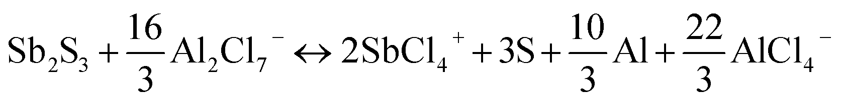
| Sb2S3 + 16AlCl4− ↔ 2SbCl4+ + 3S + 8Al2Cl7− + 10e− |
Anode reaction:
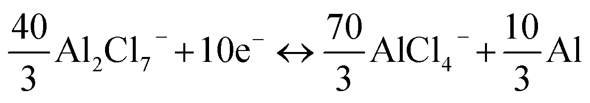
Total reaction:
Accordingly, a mixed 10-electron transfer reaction (Fig. 4a and S16†) is realized by the joint cationic and anionic reversible redox of Sb2S3, holding a surprising theoretical capacity of 789 mA h g−1. The formation and conversion of elemental S contributed to the higher theoretical capacity of the battery and explained the large polarization on the charge–discharge curves in Fig. 2d, since sulfur is an electronic insulator and has slower reaction kinetics, which also leads to lower energy efficiency (52%).40,41 It is noteworthy that the soluble charging products of SbCl4+ could shuttle into the ionic liquid electrolyte, resulting in the capacity decay of the battery. Inspired by the Li–S battery, a carbon-based interlayer was used here to mitigate the shuttle effect of the soluble products. As expected, improved electrochemical performances were achieved here by using a GA interlayer.
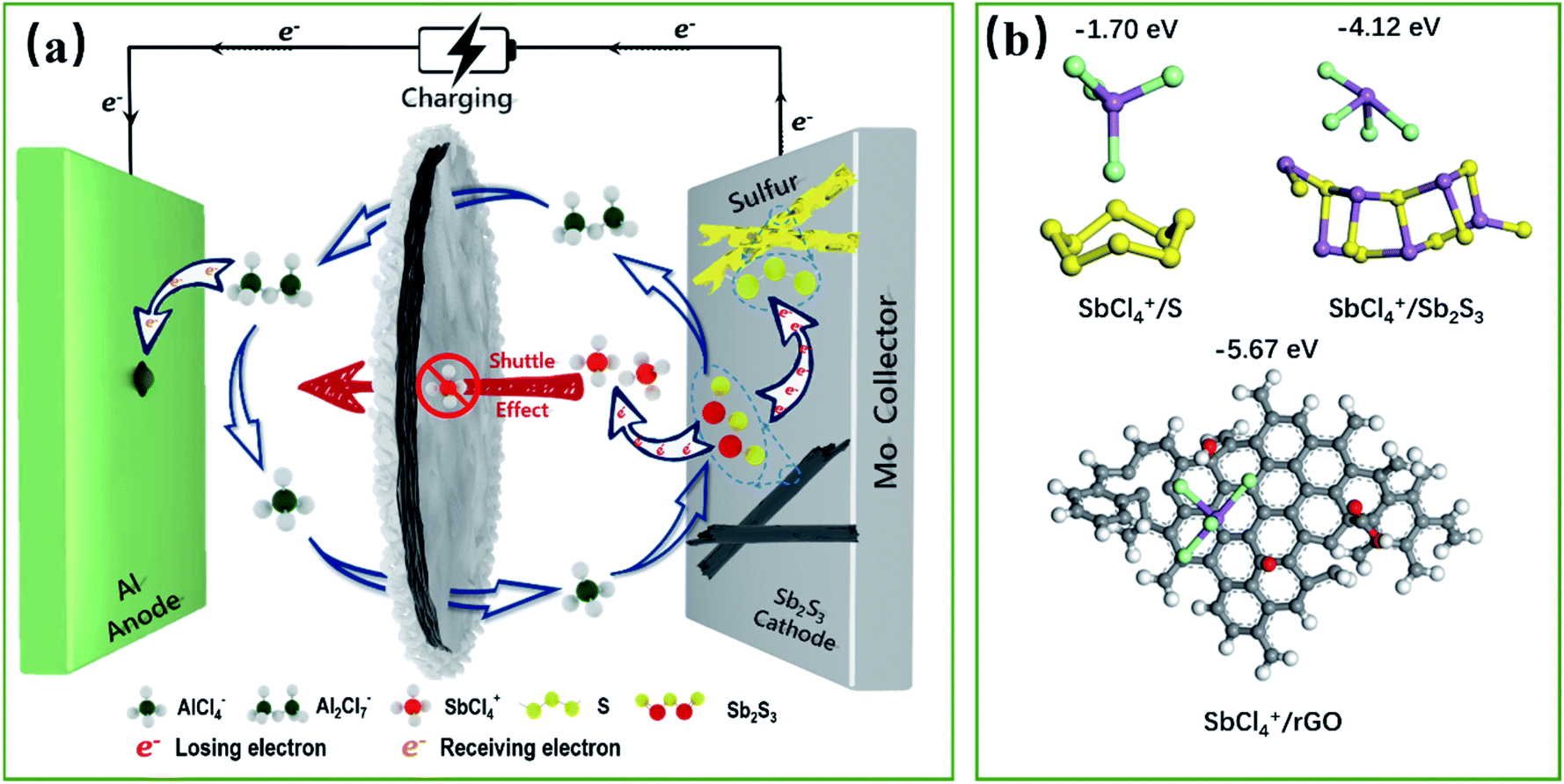 | ||
| Fig. 4 Schematic diagram of the energy storage mechanism of the Sb2S3 cathode materials during the charging process (a). Theoretical calculations of adsorption energies and structures of SbCl4+ adsorbed on S, Sb2S3 and rGO (b). | ||
Contribution of the GA interlayer to battery performance
The capacity contributions of the GA interlayer were investigated, as presented in Fig. S17.† The discharge specific capacity of pure GA presents only 25 mA h g−1 at a current density of 100 mA g−1. Fig. S18† shows the galvanostatic charge/discharge curves and cycle performance curves of the Sb2S3 cathode without a GA interlayer. It is found that the battery without a GA interlayer has similar charging and discharging platforms to the battery using a GA interlayer, but the initial discharge specific capacity presents only 191 mA h g−1, which is far less than its theoretical specific capacity. Even worse, the discharge specific capacity reduced dramatically to 37 mA h g−1 after 50 cycles. As revealed, the poor cycling performance was caused by the shuttle effect of SbCl4+ during the repeated charge/discharge processes, which could be effectively improved by using a GA interlayer.42 Fig. S19† shows the SEM morphology of the GA interlayer with a three-dimensional porous structure. The batteries after long cycles were disassembled to observe the changes in the morphology and structure of the Sb2S3 electrode and GA interlayer. Sb2S3 nanorods can be clearly seen on the initial electrode, and the elemental contents of S and Sb are close to the theoretical molar ratio of 1.5 (Fig. S20†). After 50 cycles, the rod-shaped Sb2S3 showed some defects and had decreased, while after 200 cycles, almost no Sb2S3 could be seen on the electrode surface, all of which had been converted into smaller nanoparticles, and the content of S and Sb was also significantly reduced. In contrast, a large amount of uniformly distributed Sb and S was observed on the GA interlayer after long cycling, which indicated that the original rod-like Sb2S3 had transformed and recombined, and the GA interlayer had effectively adsorbed and blocked the shuttling of charging products (Fig. S21†). As shown in Fig. S22,† the FTIR and XPS spectra illustrate the abundant oxygen-containing functional groups of –OH, –CO and –COOH in the GA interlayer. To further understand the mechanism whereby the GA interlayer inhibits the shuttle effect of SbCl4+, density functional theory (DFT) calculations were utilized to explore the possible enhanced chemisorption ability of a carbon-based interlayer toward soluble SbCl4+ (Fig. 4b). According to the DFT calculations, the binding energies for S and SbCl4+, Sb2S3 and SbCl4+, reduced graphene oxide (rGO) and SbCl4+ were estimated to be −1.70, −4.12 and −5.67 eV, respectively. Owing to the low chemisorption between the accumulated S and the soluble SbCl4+ during the cycling process, accordingly, severe shuttle effects lead to capacity decay. Fortunately, the DFT results indicate that reduced graphene oxide with oxygen-containing functional groups, such as –OH, –CO and –COOH, exhibited satisfactory chemical adsorption ability for SbCl4+. So, a GA interlayer, synthesized from graphene oxide with a gradient content of oxygen-containing functional groups (Fig. S21b†), was introduced into the battery and effectively suppressed the shuttle effect of SbCl4+ by a dual defense mechanism that integrated the physical barrier of a porous structure and the powerful chemical adsorption ability of the oxygen groups. As a result, the battery exhibits a superior discharge capacity close to its theoretical capacity and a stable cycle performance. Furthermore, Fig. S23† demonstrates the self-discharge performance of the Al–Sb2S3 battery using a GA interlayer. When the resting time is 1 or 2 h, the discharge capacities show almost no attenuation, about 575 mA h g−1, and the coulombic efficiencies are close to 100%. When the resting time increases to 6 h, the discharge capacity decays weakly and remains at 554 mA h g−1. However, when the standing time continued to increase to 12, 24, and 48 h, the capacity decays are more obvious, which are maintained at 504, 420, and 350 mA h g−1, respectively. This indicates that the GA interlayer has indeed achieved superior results in suppressing the shuttle effect of charging products in a short time, but more efforts are needed to fundamentally solve the problem, thereby further improving the battery's stability.Conclusions
In summary, unlike previously reported TMS cathode materials where energy storage is induced by the redox reaction of the cations in it alone, multivalent cationic and anionic mixed redox reactions which are imperative to further improve the battery performance were introduced into RAIBs by using a novel Sb2S3 cathode. The energy storage properties of the Sb2S3 cathode were understood to follow a joint Sb-related cationic (Sb(+3) ⇔ Sb(+5)) and S-related anionic (S(−2) ⇔ S(0)) mixed reversible redox mechanism. DFT calculations confirm that the strong chemisorption between the carbon-based interlayer with oxygen-containing functional groups and SbCl4+, effectively suppressed the shuttle effects. Furthermore, the Sb2S3 cathode exhibited outstanding cycling performance of 363 mA h g−1 at 1000 mA g−1 after 220 cycles with a record-setting cyclic performance achieved in the documented AIBs among all the metal sulfide cathode materials reported to date. The discovery of multivalent cationic and anionic mixed redox activity in metal sulfides might be a feasible solution to the pursuit of cathode materials for the further development of RAIBs.Author contributions
T. Li, T. Cai: conceptualization, methodology, validation, writing – original draft, writing – review & editing, visualization; D. Wang, H. Hu: visualization; Y. Zhang, Y. Cui, X. Li, W. Xing: validation, investigation; L. Zhao: software, formal analysis; Z. Yan: writing – review & editing, supervision, funding acquisition, project administration. All authors have given approval to the final version of the manuscript.Conflicts of interest
There are no conflicts to declare.Acknowledgements
This work was financially supported by the Taishan Scholar Foundation (tspd20210308), the Key Projects of China National Key R&D Plan (2018YFE0118200) and the Key Projects of Shandong Key R&D plan (2019JZZY010506), the 111 Progam of National College Disciplinary Innovation (B03031), the National Natural Science Foundation of China (51877216, 21905300, 22109180), the Natural Science Foundation of Shandong Province (ZR2020MB078, ZR202103040491), the Fundamental Research Funds for the Central Universities (21CX06011A), the Major Program of Shandong Province Natural Science Foundation (ZR201801280009), the PetroChina Innovation Foundation (2018D-5007-0504), the Fundamental Research Funds for the Central Universities (20CX060103A), the Postdoctoral Applied Research Program of Qingdao (qdyy20200077), and the Innovation Project for Postgraduates of China University of Petroleum (East China) (YCX2021070).References
- H. Yang, H. Li, J. Li, Z. Sun, K. He, H. M. Cheng and F. Li, Angew. Chem., Int. Ed. Engl., 2019, 58, 11978–11996 CrossRef CAS PubMed.
- J. Tu, W. L. Song., H. Lei, Z. Yu, L. L. Chen, M. Wang and S. Jiao, Chem. Rev., 2021, 121, 4903–4961 CrossRef CAS PubMed.
- R. Zhuang, Z. Huang, S. Wang, J. Qiao, J.-C. Wu and J. Yang, Chem. Eng. J., 2021, 409, 128235 CrossRef CAS.
- L. Xing, K. A. Owusu, X. Liu, J. Meng, K. Wang, Q. An and L. Mai, Nano Energy, 2021, 79, 105384 CrossRef CAS.
- Y. Hu, H. Huang, D. Yu, X. Wang, L. Li, H. Hu, X. Zhu, S. Peng and L. Wang, Nanomicro Lett., 2021, 13, 159 CAS.
- J. Varghese, S. Barth, L. Keeney, R. W. Whatmore and J. D. Holmes, Nano Lett., 2012, 12, 868–872 CrossRef CAS PubMed.
- J. Liu, J. Wang, C. Xu, H. Jiang, C. Li, L. Zhang, J. Lin and Z. X. Shen, Adv. Sci., 2018, 5, 1700322 CrossRef PubMed.
- S. Fleischmann, J. B. Mitchell, R. Wang, C. Zhan, D. E. Jiang, V. Presser and V. Augustyn, Chem. Rev., 2020, 120, 6738–6782 CrossRef CAS PubMed.
- S. Yao, J. Cui, Y. Deng, W. G. Chong, J. Wu, M. Ihsan-Ul-Haq, Y.-W. Mai and J.-K. Kim, Energy Storage Mater., 2019, 20, 36–45 CrossRef.
- W. Zhan, M. Zhu, J. Lan, H. Wang, H. Yuan, X. Yang and G. Sui, Chem. Eng. J., 2021, 408, 128007 CrossRef CAS.
- H. Li, R. Meng, Y. Guo, B. Chen, Y. Jiao, C. Ye, Y. Long, A. Tadich, Q. H. Yang, M. Jaroniec and S. Z. Qiao, Nat. Commun., 2021, 12, 5714 CrossRef CAS PubMed.
- T. Zhang, T. Cai, W. Xing, T. Li, B. Liang, H. Hu, L. Zhao, X. Li and Z. Yan, Energy Storage Mater., 2021, 41, 667–676 CrossRef.
- D. Zhang, X. Zhang, B. Wang, S. He, S. Liu, M. Tang and H. Yu, J. Mater. Chem. A, 2021, 9, 8966–8974 RSC.
- T. Gao, X. Li, X. Wang, J. Hu, F. Han, X. Fan, L. Suo, A. J. Pearse, S. B. Lee, G. W. Rubloff, K. J. Gaskell, M. Noked and C. Wang, Angew. Chem., Int. Ed. Engl., 2016, 55, 9898–9901 CrossRef CAS PubMed.
- L. D. Ellis, B. N. Wilkes, T. D. Hatchard and M. N. Obrovac, J. Electrochem. Soc., 2014, 161, A416–A421 CrossRef CAS.
- W. Guan, L. Wang, J. Tu and S. Jiao, J. Electrochem. Soc., 2020, 167, 080541 CrossRef CAS.
- Y. Tong, A. Gao, Q. Zhang, T. Gao, J. Yue, F. Meng, Y. Gong, S. Xi, Z. Lin, M. Mao, S. Peng, X. Wang, D. Xiao, D. Su, Y. Luo, H. Li, L. Chen, L. Suo and L. Gu, Energy Storage Mater., 2021, 37, 87–93 CrossRef.
- Z. Zhao, Z. Hu, Q. Li, H. Li, X. Zhang, Y. Zhuang, F. Wang and G. Yu, Nano Today, 2020, 32, 100870 CrossRef CAS.
- K. Liang, L. Ju, S. Koul, A. Kushima and Y. Yang, Adv. Energy Mater., 2019, 9, 1802543 CrossRef.
- T. Birchall, J. A. Connor and I. H. Hillier, J. Chem. Soc. Dalton Trans, 1975, 2003–2006 RSC.
- V. P. Zakaznova-Herzog, S. L. Harmer, H. W. Nesbitt, G. M. Bancroft, R. Flemming and A. R. Pratt, Surf. Sci., 2006, 600, 348–356 CrossRef CAS.
- J. Grigas, E. Talik and V. Lazauskas, Phase Transitions, 2002, 75, 323–337 CrossRef CAS.
- J. Wang, D. Feng, W. Wu, M. Zeng and Y. Li, Polym. Degrad. Stab., 1991, 31, 129–140 CrossRef CAS.
- R. Delobel, H. Baussart, J. Leroy, J. Grimblot and L. Gengembre, J. Chem. Soc., Faraday Trans., 1983, 79, 879–891 RSC.
- N. Wang, Y. Wang, Z. Bai, Z. Fang, X. Zhang, Z. Xu, Y. Ding, X. Xu, Y. Du, S. Dou and G. Yu, Energy Environ. Sci., 2020, 13, 562–570 RSC.
- K. Zhang, T. H. Lee, J. H. Cha, R. S. Varma, J. W. Choi, H. W. Jang and M. Shokouhimehr, Sci. Rep., 2019, 9, 13573 CrossRef PubMed.
- C. Barchasz, F. Molton, C. Duboc, J. C. Lepretre, S. Patoux and F. Alloin, Anal. Chem., 2012, 84, 3973–3980 CrossRef CAS PubMed.
- X. Zheng, R. Tang, Y. Zhang, L. Ma, X. Wang, Y. Dong, G. Kong and L. Wei, Sustainable Energy Fuels, 2020, 4, 1630–1641 RSC.
- X. Yu and A. Manthiram, Adv. Energy Mater., 2017, 7, 1700561 CrossRef.
- Y. Guo, H. Jin, Z. Qi, Z. Hu, H. Ji and L.-J. Wan, Adv. Funct. Mater., 2019, 29, 1807676 CrossRef.
- Y. A. Sorb, V. Rajaji, P. S. Malavi, U. Subbarao, P. Halappa, S. C. Peter, S. Karmakar and C. Narayana, J. Phys.: Condens. Matter, 2016, 28, 015602 CrossRef CAS PubMed.
- P. Makreski, G. Petruševski, S. Ugarković and G. Jovanovski, Vib. Spectrosc., 2013, 68, 177–182 CrossRef CAS.
- A. T. Ward, J. Phys. Chem., 1968, 72, 4133–4139 CrossRef CAS.
- T. Zhang, T. Cai, W. Xing, T. Li, B. Liang, H. Hu, L. Zhao, X. Li and Z. Yan, Energy Storage Mater., 2021, 41, 667–676 CrossRef.
- Z. Li, J. Liu, X. Huo, J. Li and F. Kang, ACS Appl. Mater. Interfaces, 2019, 11, 45709–45716 CrossRef CAS PubMed.
- H. Jiao, D. Tian, S. Li, C. Fu and S. Jiao, ACS Appl. Energy Mater., 2018, 1, 4924–4930 CrossRef CAS.
- H. A. Szymanski, R. Yelin and L. Marabella, J. Chem. Phys., 1967, 47, 1877–1879 CrossRef CAS.
- J. W. J. Casteel, P. Kolb, N. LeBlond, P. Hélène, A. Mercier and G. J. Schrobilgen, Inorg. Chem., 1996, 35, 929–942 CrossRef PubMed.
- H. Sun, G. Zhu, X. Xu, M. Liao, Y. Y. Li, M. Angell, M. Gu, Y. Zhu, W. H. Hung, J. Li, Y. Kuang, Y. Meng, M. C. Lin, H. Peng and H. Dai, Nat. Commun., 2019, 10, 3302 CrossRef PubMed.
- D. Zhang, X. Zhang, B. Wang, S. He, S. Liu, M. Tang and H. Yu, J. Mater. Chem. A, 2021, 9, 8966–8974 RSC.
- Y. Guo, Z. Hu, J. Wang, Z. Peng, J. Zhu, H. Ji and L. J. Wan, Angew. Chem., Int. Ed. Engl., 2020, 59, 22963–22967 CrossRef CAS PubMed.
- X. Zhang, S. Jiao, J. Tu, W.-L. Song, X. Xiao, S. Li, M. Wang, H. Lei, D. Tian, H. Chen and D. Fang, Energy Environ. Sci., 2019, 12, 1918–1927 RSC.
Footnotes |
| † Electronic supplementary information (ESI) available. See https://doi.org/10.1039/d2ta02049a |
| ‡ These authors contributed equally to this work. |
| This journal is © The Royal Society of Chemistry 2022 |