
Ultralight, highly compressible, thermally stable MXene/aramid nanofiber anisotropic aerogels for electromagnetic interference shielding†
Yiqian
Du
,
Jian
Xu
,
Jiangyu
Fang
,
Yantai
Zhang
,
Xiaoyun
Liu
 *,
Peiyuan
Zuo
and
Qixin
Zhuang
*
*,
Peiyuan
Zuo
and
Qixin
Zhuang
*
Key Laboratory of Advanced Polymer Materials of Shanghai, School of Material Science and Engineering, East China University of Science and Technology, Shanghai 200237, P. R. China. E-mail: qxzhuang@ecust.edu.cn
First published on 11th February 2022
Abstract
Recently, improving the applicability of transition-metal carbon/nitride (MXene) shielding devices through integration with nanomaterials and polymers has gradually attracted the attention of researchers. Although the addition of an insulation enhancement phase improves the mechanical properties of MXene shielding devices, it is still a challenge to avoid extensive damage to the conductive network and the reduction of the shielding efficiency (SE). Herein, an effective approach is demonstrated to construct an ultralight, conductive Ti3C2Tx MXene/aramid nanofiber (ANF) anisotropic aerogel. Thanks to the strong interfacial interaction between the MXene nanosheets and ANFs, abundant rigid skeleton and “cell wall” structures were constructed in the anisotropic aerogel. The aerogel was not only endowed with excellent compressibility and superelasticity, but also built a macroscopic conductive network, thus increasing the impedance mismatch interface, and ensuring the electromagnetic interference (EMI) shielding performance of the device. At an ultra-low Ti3C2Tx content (0.58 vol%), the conductivity of the composite aerogel reached a maximum of 854.9 S m−1 and the EMI SE reached 65.5 dB, which is the best efficiency value of an aerogel based on ANFs so far. In addition, the anisotropic Ti3C2Tx/ANF aerogel had consistent thermal stability and flame retardant properties. The nanosheet edge protection based on ANFs delayed the oxidation of MXene, and the EMI SE still reached 59.1 dB after 2 h of exposure in air at 250 °C. Therefore, the ultralight, superelastic, and thermally stable Ti3C2Tx/ANF anisotropic aerogel prepared in this work showed excellent application prospects in various extreme conditions.
Introduction
With the rapid development of information technology and portable wearable devices, small volume and lightweight electromagnetic interference (EMI) shielding materials are urgently needed to cope with the complex electromagnetic wave (EMWs) environment, to ensure the stable operation of equipment and protect human health.1–4 Different from the fatal weakness of traditional metal materials with a high density and ease of corrosion, transition-metal carbon/nitride (MXene), as an emerging two-dimensional sheet material, exhibits great potential in the field of electromagnetic shielding due to its excellent electrical conductivity and abundant interface groups.5–10 It is urgent to overcome the weak interaction between MXene nanosheets, for the better usage of their unique 3D structural advantages, thus improving their mechanical properties and oxidation resistance.11 In recent years, freeze-drying,12 hard-template,13 chemical reduction,14 and chemical-crosslinking15 methods have been widely used to construct MXene-based 3D structures. Gao et al.16 prepared a 3D MXene sponge network using sponge as a substrate material. Due to the strong van der Waals forces between the MXene and the matrix, the MXene can be well anchored on the sponge. The load of MXene in the porous structure can be easily adjusted by altering the concentration of the impregnation solution. For different application scenarios, different porous substrates, such as polymers and metal foams, can be selected to meet different needs. Liu et al.17 constructed a superelastic MXene/polyimide (PI) aerogel by utilizing the strong polar interface interaction between the active groups of MXene and the polar PI chains. In general, using polymers or nanomaterials as reinforcement phases is a widely adopted strategy by researchers that can improve the mechanical properties of MXene-based composite 3D structures through chemical bonds, hydrogen bonds, and van der Waals forces.Conductivity is a key index to measure electromagnetic shielding devices.18,19 However, the insulating polymer and nano-filler will inevitably damage the integrity of the conductive network, thus reducing the conductivity and then leading to the loss of the shielding efficiency (SE).6,20 Therefore, until now, there has been an irreconcilable contradiction between the pursuit of excellent electromagnetic shielding performance and mechanical properties that meet the actual commercial needs. After adding insulation reinforcement to ensure suitable mechanical properties, it is still a challenge to preserve the conductive network's integrity.
Herein, we successfully prepared a Ti3C2Tx MXene/aramid nanofiber (ANF) anisotropic aerogel by directional freezing and freeze-drying. Compared with the incomplete conductive network in a conventional isotropic aerogel, the anisotropic aerogel was endowed with a macroscopic ordered conductive network through the design of an anisotropic structure. In addition, the “cell wall” structure connecting the ordered structures not only optimized the integrity of the aerogel conductive network, but also increased the impedance mismatch interface and improved the multiple reflection efficiency of EMWs. The addition of ANFs can increase the bonding strength, thus improving the mechanical properties of the MXene aerogel interface and protecting the edge of the nanosheets in contact with oxygen, which can further inhibit the slow oxidation of MXene. Aerogels based on porous structures benefit from the addition of ANFs, which can introduce more interfaces, therefore effectively attenuating the EMWs through the interface polarization effect. Benefiting from the above synergistic effects, the anisotropic aerogel with 0.58 vol% of Ti3C2Tx achieved a high EMI SE of 65.5 dB and excellent absolute shielding effectiveness (SSE/t) reaching 11![[thin space (1/6-em)]](https://www.rsc.org/images/entities/char_2009.gif) 391 dB cm2 g−1, which is the best result reported for a composite aerogel based on ANFs so far. In addition, due to its unique anisotropic structure and the enhanced effect of the ANFs on MXene, the Ti3C2Tx/ANFs anisotropic aerogel not only achieved outstanding compressive strength (93.59 kPa) and resilience, but also remained undeformed under flame combustion. Specifically, the composite aerogel maintained a consistent EMI SE (59.1 dB) after exposure to 250 °C air for 2 hours. Accordingly, the ultralight, superelastic, and thermally stable Ti3C2Tx/ANF anisotropic aerogel showed excellent application prospects in various extreme conditions.
391 dB cm2 g−1, which is the best result reported for a composite aerogel based on ANFs so far. In addition, due to its unique anisotropic structure and the enhanced effect of the ANFs on MXene, the Ti3C2Tx/ANFs anisotropic aerogel not only achieved outstanding compressive strength (93.59 kPa) and resilience, but also remained undeformed under flame combustion. Specifically, the composite aerogel maintained a consistent EMI SE (59.1 dB) after exposure to 250 °C air for 2 hours. Accordingly, the ultralight, superelastic, and thermally stable Ti3C2Tx/ANF anisotropic aerogel showed excellent application prospects in various extreme conditions.
Experimental
Materials and reagents
Titanium aluminum carbide (Ti3AlC2, 400 mesh) was supplied by Jilin 11 Technology Co, Ltd in China. Hydrofluoric acid (HCl) was supplied by Sinopharm Group Chemical Reagent Co, Ltd. Dimethyl sulfoxide (DMSO) was provided by Hwrk Chemical Co, Ltd. Potassium hydroxide (KOH) and lithium fluoride (LiF) were provided by Shanghai Macklin Biochemical Co, Ltd. Surgipath Paraplast was supplied by Leica Biosystems Inc. Kevlar 29 fibers were purchased from Dupont, USA.Preparation of the ANF suspension
The ANF dispersions were derived by deprotonation and dissociation of macroscopic aramid thread.21 Briefly, 1.0 g of Kevlar 29 fibers and 1.5 g of KOH were added into 500 mL of DMSO. The Kevlar/KOH/DMSO suspension was magnetically stirred at room temperature for 1 week to obtain an ANF/DMSO suspension with a concentration of 2 mg mL−1. The obtained ANF colloids irradiated by a laser showed the Tyndall effect, as shown in Fig. S1c.†Synthesis of Ti3C2Tx MXene
The delaminated Ti3C2Tx MXene was synthesized according to the etching and delamination method with HCl/LiF as previously reported.6 Specifically, 1.0 g of LiF was mixed with 20 mL of HCl with a concentration of 9 mol L−1 and stirred in an ice water bath for 1 h. Then, 1.0 g of Ti3AlC2 (MAX) powder was slowly added into the transparent mixture within 10 minutes, followed by moderate stirring at 35 °C for 24 h. The obtained clay-like Ti3C2Tx was washed with deionized water via centrifugation at 6500 rpm until the supernatant pH reached approximately 6.0. After sonication under the protection of argon for 1 h, followed by centrifugation at 3500 rpm for 1 h, a uniform supernatant with Ti3C2Tx MXene was prepared.Synthesis of the anisotropic Ti3C2Tx/ANF aerogel
200 mL of deionised water was poured into a 100 mL suspension of ANFs and stirred rapidly by magnetic force for 2 hours. Then, MXene (Ti3C2Tx) suspensions with different contents (20 wt%, 40 wt%, 60 wt%, 80 wt%) were added to form the wet ANF gel by vacuum filtration. After that, the obtained gel was stirred vigorously by a high-speed dispersion mixer at 2000 rpm for 30 min. Subsequently, the Ti3C2Tx/ANF mixture gel was directionally frozen in a Teflon mould under liquid nitrogen and dried at −56 °C under a vacuum of ∼6 Pa by freeze-drying for 48 h. Meanwhile, depending on the mass ratio of Ti3C2Tx in the anisotropic Ti3C2Tx/ANF aerogel (10, 20, 40, 60 and 80 wt%), the obtained aerogels were denoted as aTA-1, aTA-2, aTA-3, aTA-4, and aTA-5, respectively. The Ti3C2Tx/ANF mixture gel loaded into the mold was also put into a refrigerator for freezing to obtain an isotropic aerogel as the reference sample, designated as iTA-1, iTA-2, iTA-3, iTA-4, and iTA-5. The concentrations of Ti3C2Tx in the iTA samples were consistent with those of the aTA samples described above.Characterization
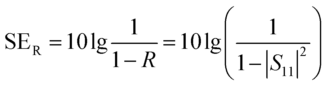
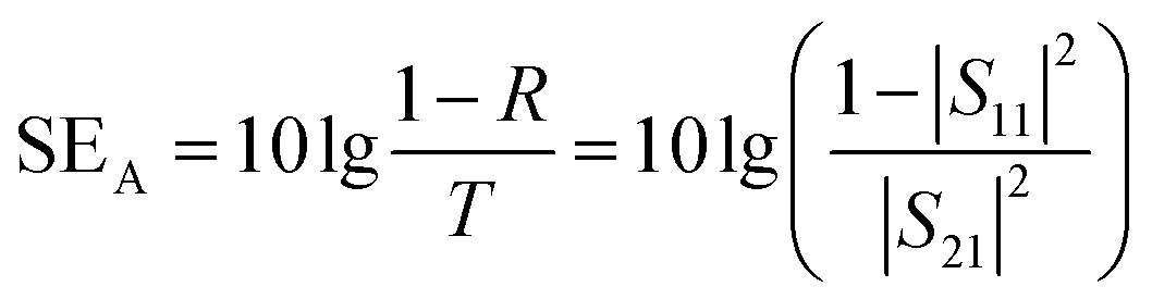
The anisotropic morphology was characterized by field emission scanning electron microscopy (FESEM, Hitachi S-4800, Japan) equipped with an energy dispersive spectrometer (EDS) system at an acceleration voltage of 15.0 kV. The sample was pasted on the test table with conductive tape, and gold spraying was carried out for 60 s before the test. Transmission electron microscope (TEM, JEOL JEM-2100, Japan) images were obtained with an acceleration voltage of 200 kV. X-ray diffraction spectroscopy (XRD, Ultima IV, Japan) was used to characterize the crystallinity of the samples with Cu Kα (0.01541 nm) radiation, scanning from 5° to 60°. The Fourier Transform infrared spectroscopy (FTIR, Bruker Vertex 70, Germany) spectra were acquired under the spectral range from 400 to 4000 cm−1, to measure the chemical functional group changes of the ANFs, Ti3C2Tx, and TA aerogel. Raman (Horiba HR Evolution, French) spectra of the samples were recorded with a 532 nm wavelength laser. X-ray photoelectron spectroscopy (XPS, Thermo Scientific K-Alpha, USA) spectra were acquired to analyse the element chemical states. The mechanical properties of the samples were tested by a dynamic biomaterial mechanics testing system (Electroforce 3200, TA, USA) and the maximum compressive strain was set to 40%. Thermogravimetric analysis (TGA) was carried out on a thermal analyser (STA 449F5, Netzsch, Germany) with a heating rate of 10 °C min−1 ranging from 30 to 800 °C in a nitrogen atmosphere. Infrared images of the aerogels were obtained by an infrared thermal imager (Hikvision, H36, China).The conductivity was measured by a four-probe resistivity meter (RTS-8, China). The electromagnetic shielding performance of the samples was characterized by a vector network analyser (Agilent, PNA-N5244A, USA) with a frequency range of 8.2–12.4 GHz. All samples were obtained from a custom mould and immersed with paraplast as shown in Fig. S3.† The coefficients of absorption (A), reflection (R), and transmission (T) were calculated from the scattering parameters (S11, S21) according to the following equation:
| R = |S11|2 | (1) |
| T = |S21|2 | (2) |
| A = 1 − T − R | (3) |
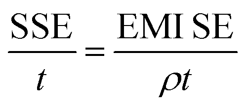
The total value of EMI SE (SET), reflection shielding efficiency (SER), absorption shielding efficiency (SEA), multiple internal reflection shielding efficiency (SEM) and SSE/t can be calculated via the following relationships:
 | (4) |
 | (5) |
| SET = SER + SEA + SEM | (6) |
 | (7) |
When the thickness of the samples is close to or larger than the skin depth or when the SET reaches higher than 15 dB, the SEM can be negligible.1
Results and discussion
Synthesis and structural characterization
As shown in Scheme 1, the anisotropic Ti3C2Tx/ANF aerogel was obtained by the “directional ice template” method. Firstly, Ti3C2Tx was obtained by etching Ti3AlC2 with HF acid produced from LiF and HCl. The relevant electron microscope pictures are shown in Fig. S2.† Meanwhile, through the action of KOH/DMSO, Kevlar fibers underwent a continuous deprotonation process and finally formed ANFs. After solvent exchange, the ANF/DMSO gel was mixed with Ti3C2Tx in a certain proportion and formed a stable hydrogel under the action of hydrogen bonds. Finally, the hydrogel was frozen in a homemade mould with liquid nitrogen to fix the structure orientation and then the aerogel was formed through a freeze-drying process. The lightweight characteristics of the aerogel are shown in Fig. S1.†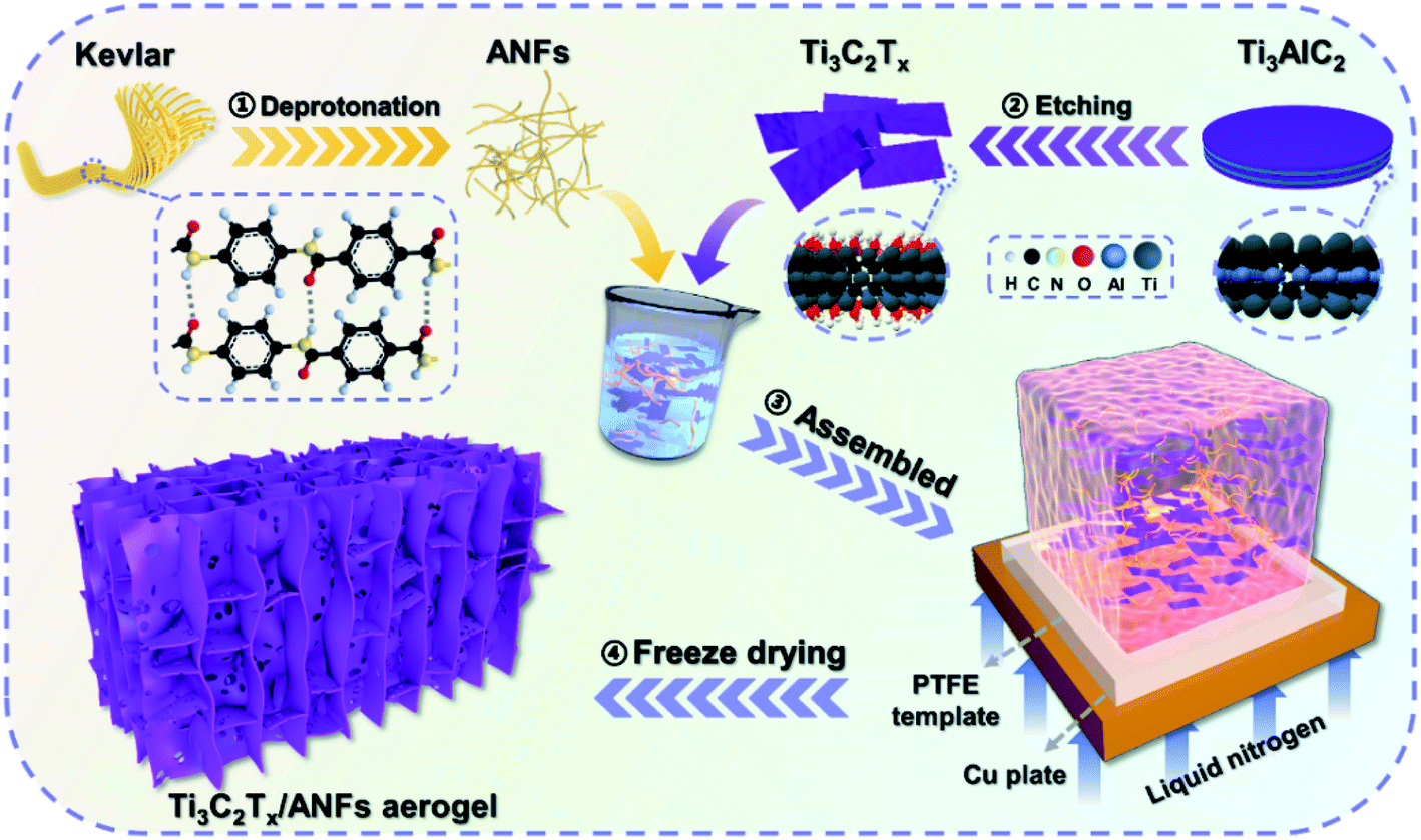 | ||
| Scheme 1 Schematic illustration of the preparation of an anisotropic Ti3C2Tx/ANF aerogel. | ||
In order to prove that Ti3C2Tx MXene was successfully synthesized and the hydrogen bonds were stably combined with the aerogel matrix, the crystal structure of the ANFs, Ti3AlC2, Ti3C2Tx, and aTA-3 were analysed, as shown in Fig. 1a. First of all, the characteristic peak of the (002) crystal plane in the characterized material shifted from 9.5° to 6.3°, indicating that interlayer Al was etched and the interlayer was transformed from tight chemical bonds to loose non-covalent bonds, resulting in larger interlayer spacing.22 In addition, three wide peaks at 20.8°, 23.1°, and 28.5° in the ANFs corresponded to the (110), (200), and (004) crystal planes, respectively.23 As shown in the XRD spectra of aTA-3, the corresponding characteristic peaks appeared in the composite aerogel. Meanwhile, the (002) crystal plane shifted slightly to a smaller angle. This is attributed to the fact that after hydrogen bonding, ANFs were embedded into the lamellar structure of MXene, increasing the interlamellar spacing.
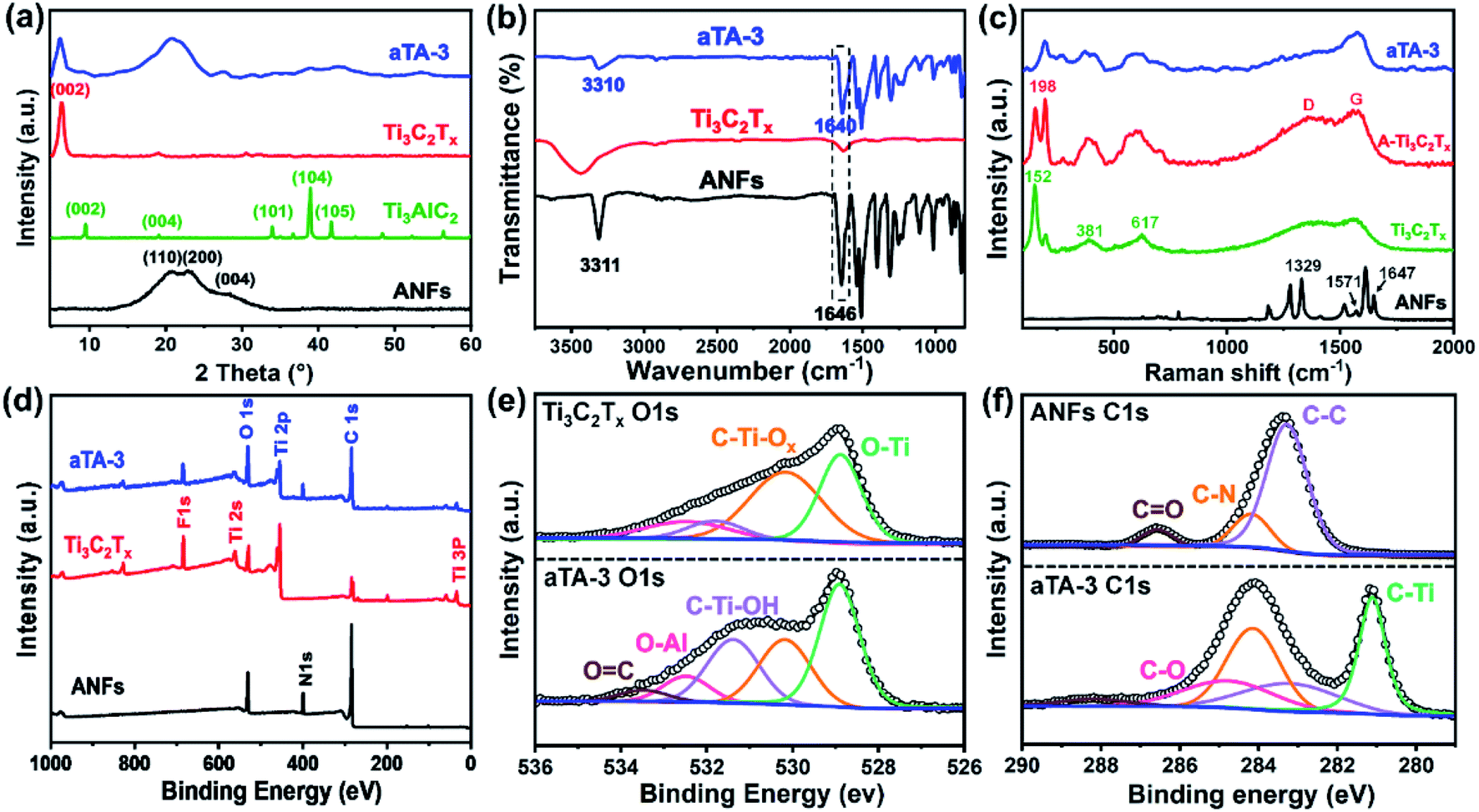 | ||
| Fig. 1 (a) XRD pattern of the ANFs, Ti3AlC2, Ti3C2Tx and aTA-3. (b) FT-IR spectra. (c) Raman spectra of Ti3C2Tx, Ti3C2Tx aerogel and aTA-3. (d) XPS survey spectra and (e) XPS spectra of O 1s for Ti3C2Tx and aTA-3, and (f) C 1s for ANFs and aTA-3. | ||
Fourier transform infrared spectroscopy (FT-IR) was carried out to demonstrate the functional groups and hydrogen bonding between the Ti3C2Tx MXene and ANFs. As shown in Fig. 1b, the FT-IR spectrum of the ANFs showed the corresponding N–H stretching vibration at 3318 cm−1 and carbonyl (C![[double bond, length as m-dash]](https://www.rsc.org/images/entities/char_e001.gif) O) stretching vibration band at 1646 cm−1.23 The FT-IR spectrum of the Ti3C2Tx MXene presented bands at 3424 cm−1 and 1635 cm−1, which corresponded to the vibration absorption of the hydroxyl group (–OH) and C–O, respectively.24 The FT-IR spectrum of the composite aerogel showed no obvious changes of the characteristic peaks. More importantly, the characteristic peak of the carbonyl (CO) group in the ANFs shifted from 1646 cm−1 to 1640 cm−1, and the presence of hydrogen bonds was confirmed by the redshift of the characteristic peak. This may be due to the influence of the chemical environment around the CO bond by the groups enriched on the surface of MXene (such as –OH, –F) and the carbonyl group acting as the hydrogen bond receptor, which led to the deviation of the characteristic peak.
O) stretching vibration band at 1646 cm−1.23 The FT-IR spectrum of the Ti3C2Tx MXene presented bands at 3424 cm−1 and 1635 cm−1, which corresponded to the vibration absorption of the hydroxyl group (–OH) and C–O, respectively.24 The FT-IR spectrum of the composite aerogel showed no obvious changes of the characteristic peaks. More importantly, the characteristic peak of the carbonyl (CO) group in the ANFs shifted from 1646 cm−1 to 1640 cm−1, and the presence of hydrogen bonds was confirmed by the redshift of the characteristic peak. This may be due to the influence of the chemical environment around the CO bond by the groups enriched on the surface of MXene (such as –OH, –F) and the carbonyl group acting as the hydrogen bond receptor, which led to the deviation of the characteristic peak.
The Raman spectra are shown in Fig. 1c. The peak at 1329 cm−1 in the ANFs corresponded to in-plane bending of C–H, the peak at 1571 cm−1 corresponded to in-plane coupling deformation of the N–H and C–N stretching modes, and the peak at 1647 cm−1 corresponded to CO, C–N stretching and N–H bending.18 For the Raman spectrum of Ti3C2Tx, the peak at 152 cm−1 was attributed to titanium dioxide, which was caused by the inevitable oxidation of Ti3C2Tx.25 The wide peaks near 381 cm−1 and 617 cm−1 were assigned to the Ti–C vibration.26 By comparing the Raman spectra of two different forms of Ti3C2Tx, the increased peak intensity of the D and G bands may be influenced by the structure of the aerogel. The larger specific surface area enhanced the irreversible oxidation of Ti3C2Tx in air, which was further proved by the increase of the peak intensity of Ti–O at 198 cm−1.27,28 Meanwhile, the peak at 198 cm−1 suggested that the Ti3C2Tx aerogel contained more active groups (such as –OH and –O), making contributions to the bonding with ANFs through hydrogen bonds. Interestingly, as shown in the Raman spectrum of the composite aerogel, the peaks at 152 cm−1 disappeared, and the intensity of the D and G peaks decreased. This can be explained by the ANFs providing a protective effect on the oxidation of Ti3C2Tx.
XPS played a key role in detecting the surface chemistry in the composite aerogel and the abundant active groups on the surface of Ti3C2Tx and the ANFs were characterized by XPS. As shown in Fig. 1d, the XPS wide-scan spectra revealed an extra N 1s peak in the aTA-3 composite aerogel, and the peak intensity of O 1s and C 1s was increased when compared with the other samples. The high-resolution O 1s spectra are shown in Fig. 1e, and the O–Al, C–Ti-Ox and O–Ti characteristic peaks appeared at 532.48 eV, 530.18 eV and 528.88 eV, respectively.29 For the high-resolution C 1s spectra (Fig. 1f), C–Ti and C–O peaks were detected at 281.08 eV and 284.28 eV, which again proved the successful preparation of the composite aerogel.18 More importantly, with the addition of MXene, the CO peak shifted from 286.6 eV to a higher binding energy of 288.08 eV, while the C–Ti–OH peak in the O 1s spectrum moved to a lower binding energy. The CO competed with the active surface groups of MXene and formed intermolecular hydrogen bonds with each other, resulting in a decrease in electron cloud density and an increase in the binding energy of CO. These results were consistent with the previous FT-IR results; that is, the composite aerogel had extensive hydrogen bond interactions and the uniform dispersion degree of the filler, thus improving the mechanical strength of the aerogel significantly.
The microstructure of the composite aerogel was characterized by scanning electron microscopy (SEM). As shown in Fig. 2a–c, the isotropic aerogels with 40 wt% Ti3C2Tx content showed rich, non-arranged porous structures. For the ANF aerogels shown in Fig. 2d–f, the rigid skeleton of ANFs showed an orderly arrangement. In Fig. 2g–i, it was obvious that after the addition of Ti3C2Tx, the rigid aerogel structures were connected through flocculent bridge structures. This can be attributed to the fact that in the process of ice crystal growth, due to hydrogen bonding, the entanglements between larger Ti3C2Tx and ANFs cannot be evenly distributed as a pure ANF aerogel, and the accumulation of Ti3C2Tx/ANFs appeared in the horizontal direction. As shown in Fig. 2j–l, in the morphology of the aerogel with a high Ti3C2Tx content, more regular bridging structures and “cell wall” structures appeared between the rigid skeletons.30 The hydrophilicity of MXene was better than that of the ANFs due to the abundance of active groups on its surface, and as the MXene content increased, the solid–liquid interfacial tension changed during directional freezing, and the rigid skeleton in the aerogel was further subjected to extrusion during ice crystal growth, resulting in a more regular arrangement and wider spacing.31 Meanwhile, as shown in Fig. 2i and l, the homogeneous dispersion of MXene resulted in the formation of a large number of pore structures inside the “cell wall”, increasing the electromagnetic wave transmission paths and interfacial polarisation losses. This further effectively reduced the density and improved the electromagnetic shielding performance.
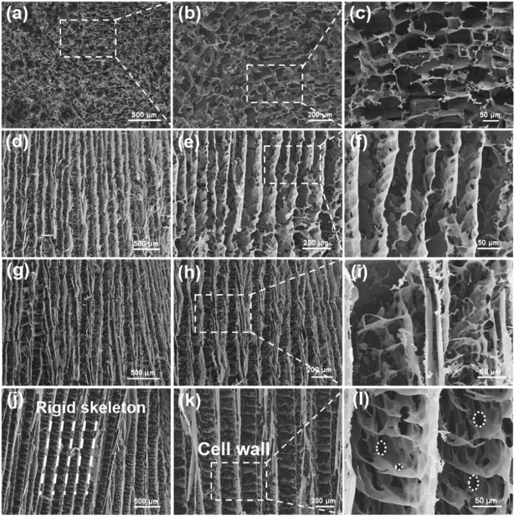 | ||
| Fig. 2 SEM images of (a–c) iTA-3, (d–f) the ANF aerogel, (g–i) aTA-3, and (j–l) aTA-5. | ||
Mechanical performance
In order to prove the supporting effect of the rigid skeleton in the anisotropic aerogel, the compressive strength and resilience performance were studied. Fig. 3a and b show the resilience of the anisotropic aerogels under pressure from different directions. In Fig. 3a, the force was perpendicular to the orientation direction, and the aerogel exhibited excellent resilience. After being compressed to 40% deformation and then released, it was observed that the strain can be almost completely recovered. In comparison, when the force of the aerogel was parallel to the orientation direction (Fig. 3b), after 40% deformation, the aerogel was difficult to fully recover, and a negative Poisson's ratio was observed. This is also accurately expressed by the stress–strain curves in Fig. 3f. Fig. 3c shows the effect of different MXene contents on the mechanical properties of the aerogels. The maximum compressive stress of the pure ANF aerogel at 40% strain was 86.85 kPa. As the content of MXene increased, the mechanical properties of the aerogels showed a downward trend. The maximum compressive stresses of aTA-2, aTA-3 and aTA-4 reached 69.22 kPa, 64.16 kPa and 44.29 kPa, respectively. The addition of MXene slightly damaged the integrity of the aerogel, resulting in a decrease in mechanical properties. However, compared with the pure MXene aerogel, the maximum compressive strength was greatly enhanced, thus greatly improving the practicability of the MXene-based aerogel. Benefiting from the unique anisotropic structure, the shielding device still has superior mechanical strength to meet the needs in a variety of scenarios.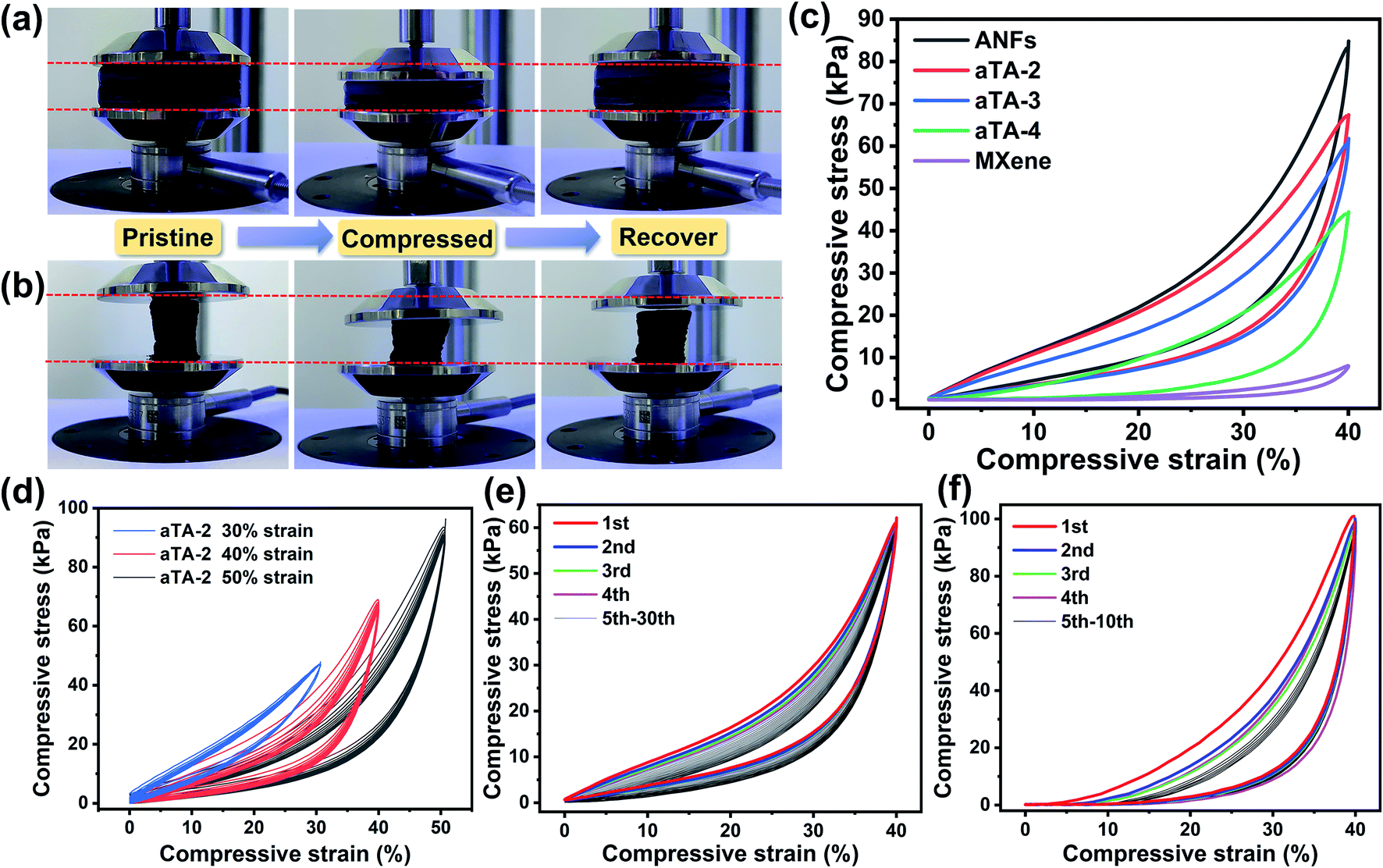 | ||
| Fig. 3 Digital images of the compression test along the (a) vertical direction and (b) parallel direction. (c) A series of anisotropic aerogel stress–strain curves with different concentrations of MXene. (d) Stress–strain curves for 10 compression cycles of aTA-2 at 30%, 40% and 50% compressive strain. (e) Stress–strain curves of aTA-3 with 30 compression cycles along the vertical direction. (f) Stress–strain curves of aTA-3 with 100 compression cycles along the parallel direction. | ||
Fig. 3d, S4 and S5† show the stress–strain curves of the composite aerogel for 10 compression cycles at a range of strain gradients for different Ti3C2Tx contents. The compressive strength of aTA-2 gradually increased with increasing compressive strain and reached a maximum compressive strength of 93.59 kPa at 50% strain. Fig. S6,†3e and S7 showed the stress and strain curves of aTA-2, aTA-3, and aTA-4 under vertical stress cycles for 30 times. Due to the rigid skeleton and “cell wall” structure formed by the strong interface interaction between the ANFs and MXene, the aerogels with different contents showed an excellent superelasticity. It is difficult to observe the deformation of aTA-2 and aTA-3 when comparing the state before and after 30 compression cycles. Obviously, under low strain, the compressive modulus increased slowly, and the aerogel mainly relied on the deformation of the “cell wall” structure to resist pressure. As the compressive strain approaches 40%, the space of the porous “cell wall” structure inside the aerogel was gradually compressed to a minimum, and the supporting effect of the rigid skeleton made the compressive strength rapidly increase. In addition, with the increasing number of cycles, the aerogel showed slight fatigue and relaxation, and its rebound speed slowed down, presumably due to the destruction of the microscopic “cell wall” structure.
Electrical conductivity and EMI shielding performance
Fig. 4 and S8† show histograms of the conductivity of the anisotropic and isotropic aerogels at different Ti3C2Tx contents. As the Ti3C2Tx content increases, the anisotropic structure of the aerogel forced an ordered distribution of the conducting phase MXene, which greatly increased the conductivity of the aerogel, reaching a maximum value of 854.9 S m−1 for aTA-5. In comparison, the conductivity of the isotropic aerogel was substantially lower than that of the above aerogel. This can be explained by the fact that the addition of insulating nanofibres in a disordered structure severely disrupts the conductive network of the shielding device and reduces the shielding efficiency.32,33Fig. 5a and b show the EMI shielding performances of anisotropic and isotropic composite aerogels in the frequency range of 8.2–12.4 GHz (X-band). The results exhibited smooth and continuous curves, indicating that the composite aerogel showed stable and reliable performance in the test band. With the increase of the Ti3C2Tx content, the performance of both aerogels improved significantly, and the EMI shielding performance of the anisotropic aerogel was more impressive. When the thickness of the aerogel was 2.5 mm and the Ti3C2Tx content was 40 wt%, the EMI SE of aTA-3 at 12.4 GHz reached 44.7 dB, and its shielding efficiency percent reached 99.996% (Fig. S9†), which was fully qualified for the current commercial requirements (40 dB). However, the performance of the isotropic structure with a thickness of 2.6 mm was only less than 40 dB. More importantly, the EMI SE of aTA-5 with thickness of 2.5 mm and density of 23.3 mg cm−3 was greater than 60 dB in the frequency range of 8.2–12.4 GHz, and even reached the highest value of 65.5 dB at 12.4 GHz. To the best of our knowledge, this is the highest value that has been reported in the work of composite aerogels based on Kevlar.31,34 Meanwhile, the composite aerogels showed a positive correlation between shielding efficiency and thickness, and aTA-3 reached more than 55 dB in the X-band at a thickness of 3.2 mm (Fig. 5c). In addition, the performance of the shielding device, which received EMWs along the parallel direction, is shown in Fig. S10.† Compared with the normal vertical direction to receive EMWs, its performance is greatly reduced. Due to the impedance mismatch interface and the reduction of loss sites, it was difficult for shielding devices to construct effective synergies against EMWs. This work provided a guiding basis for the practical application of anisotropic shielding devices.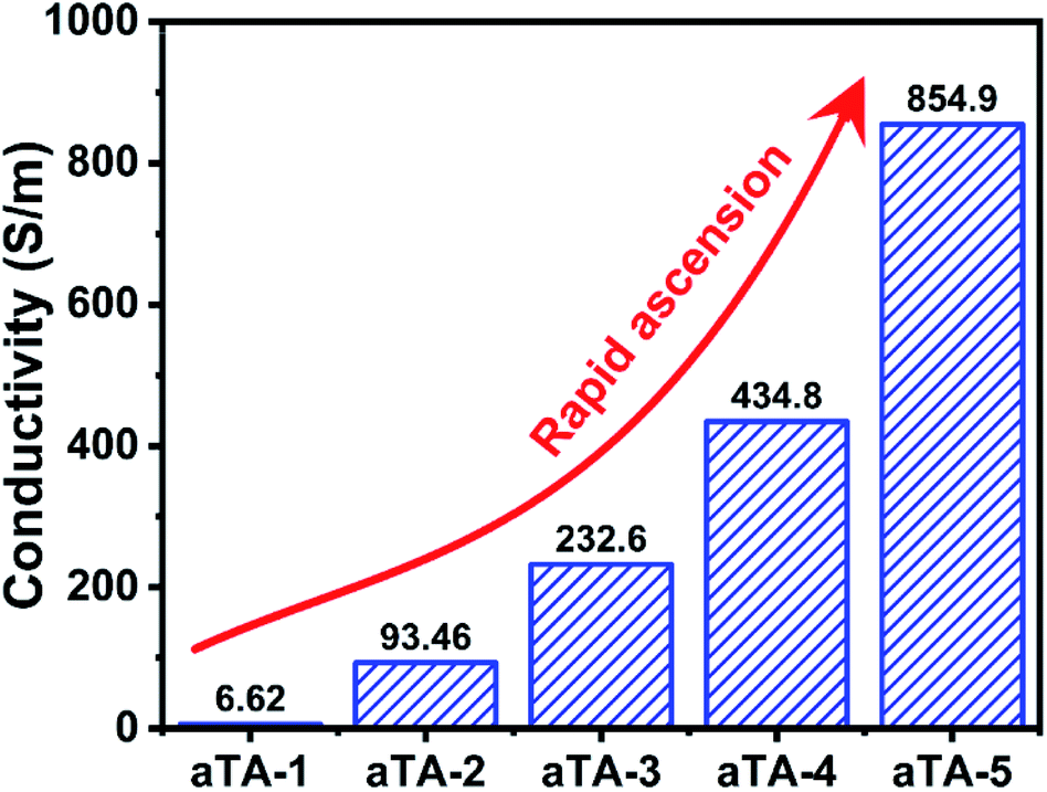 | ||
| Fig. 4 Histogram of the conductivity of anisotropic aerogels with different MXene contents. | ||
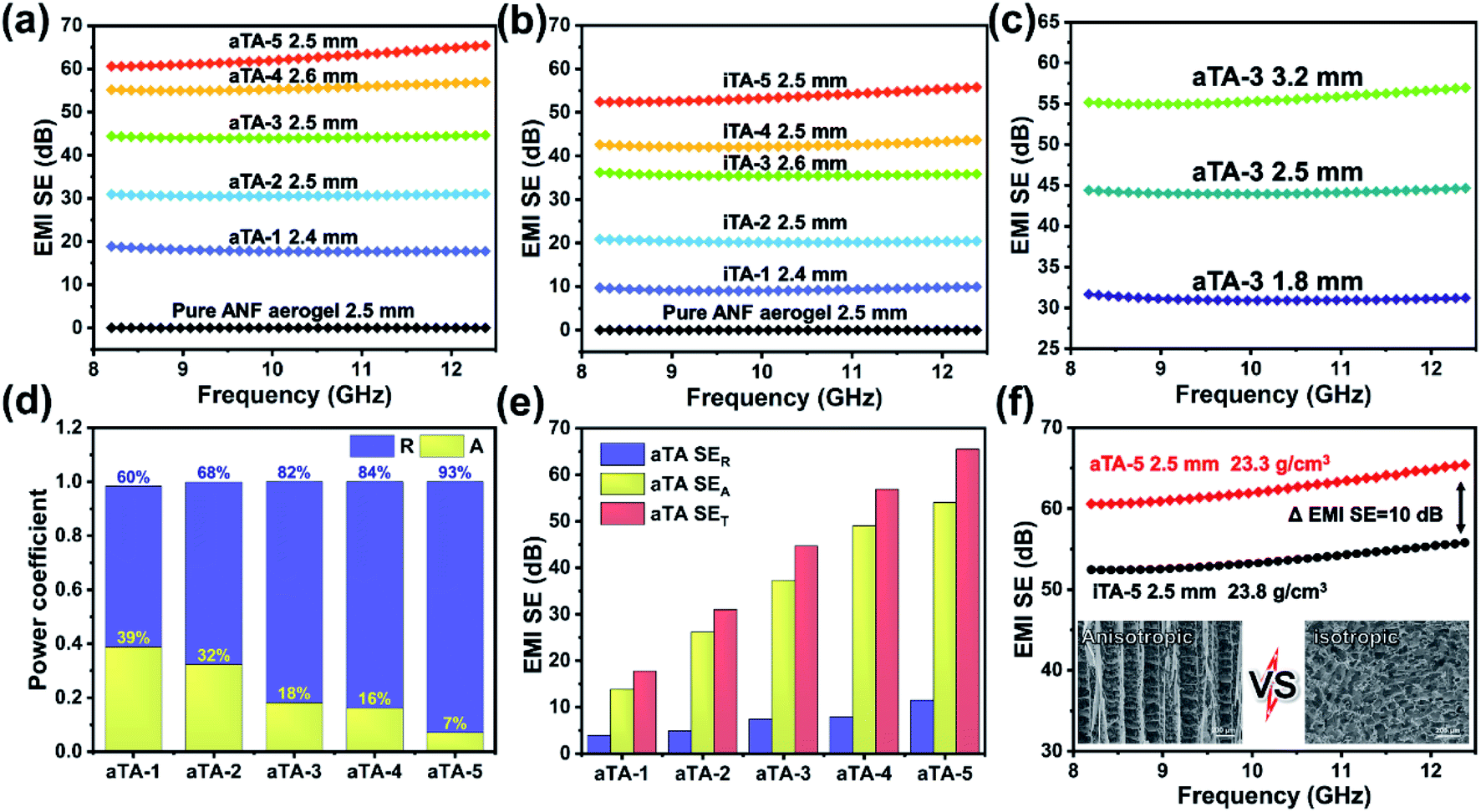 | ||
| Fig. 5 (a) EMI shielding performance of anisotropic aerogels with different Ti3C2Tx contents. (b) EMI shielding performance of the isotropic aerogels. (c) Comparison of the shielding performance of aTA-3 aerogels with different thicknesses. (d) SET, SEA and SER values at the frequency of 12.4 GHz of the anisotropic aerogels with different contents of Ti3C2Tx. (e) The power coefficients reflection (R) and absorption (A) of the anisotropic aerogels with different contents of Ti3C2Tx. (f) Comparison of the anisotropic and isotropic aerogels. | ||
As shown in Fig. 5d and S11b,† the analysis of coefficients A and R can further explain the shielding mechanism of the composite aerogels. Obviously, with the increase of the MXene content, the coefficient R gradually occupied the main role of the shielding effect. Due to the impedance mismatch caused by high conductivity, most of the incident EMWs were intercepted in the way of reflection, and the surviving EMWs were absorbed inside the aerogel. Fig. 5e and S11a† show that the increase of the Ti3C2Tx content in the anisotropic and isotropic composite aerogels was accompanied by a significant increase in absorption efficiency, while the reflection efficiency was slightly increased due to the conductive filler in the device. The SEA of the anisotropic structure was significantly higher than that of the isotropic structure. The absorption efficiency of all isotropic composite aerogels was surpassed by anisotropic aerogels with only 60 wt% Ti3C2Tx content. In particular, with high MXene content, the EMI SE of the anisotropic aerogels is 10 dB higher than that of the isotropic structures (Fig. 5f). Since SER of the anisotropic structure was higher than that of the isotropic structure, it was speculated that a more complete conductive network was constructed in the anisotropic structure, resulting in higher reflection efficiency.30,35 Therefore, it could be concluded that the long-range ordered and regular structure of the anisotropic aerogel enabled the device to achieve better performance.
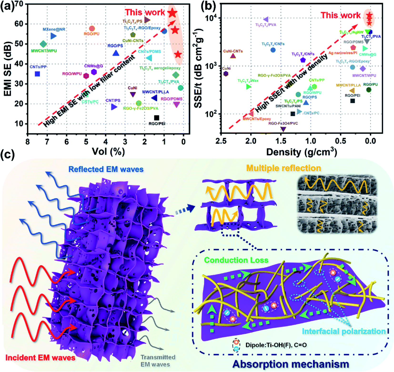
As shown in Fig. 6a and Table S1,† compared to the reported EMI shielding composites containing graphene, metal, or MXene, the anisotropic composite aerogel displayed a superb EMI SE at an ultralow filler content. When the filler contents were 0.58 vol% and 0.44 vol%, the EMI SE reached 65.5 dB and 56.9 dB, respectively. What's more, as electromagnetic shielding materials are widely used in the 5G, military, and aerospace fields, the density and thickness of the shielding devices are important indexes to measure the properties of composite materials. Absolute shielding effectiveness was defined as EMI SE divided by the thickness and density of the material, which was a key indicator to measure the lightweight characteristic of the material. Compared with previous literature, the advantages of anisotropic composite aerogels in density and SSE/t performance were highlighted. Fig. 6b and Table S1† show that the composite aerogels exhibited extremely low density and SSE/t superior to most composite materials. It is noteworthy that the SSE/t of aTA-5 showed an extremely high value of 11391 dB cm2 g−1 when the density was only 23.3 mg cm−3. These outstanding results showed that the anisotropic aerogels exhibited superior performance over most shielding materials at ultra-low filler content and density, and have been proved to be very promising in many commercial areas.
 | ||
| Fig. 6 (a) EMI SE versus Ti3C2Tx content (vol%) and (b) SSE/t versus density of the anisotropic Ti3C2Tx/ANF aerogels compared with previous reports. (c) Electromagnetic shielding mechanism of the anisotropic Ti3C2Tx/ANF aerogel. | ||
Fig. 6c briefly shows the mechanism of the anisotropic composite aerogels achieving high shielding performance. Due to the high electrical conductivity of the shielding materials and the difference of wave impedance between the interface and air,7 about 90% of the EMW loss was attenuated by reflection. The surviving EMWs were lost through multiple reflections/scattering inside the aerogel. More importantly, based on directional freezing, ordered channels and array “cell wall” structures were formed in the aerogel, which introduced more impedance mismatch interfaces, thereby enhancing the multiple reflections of internal EMWs. Multiple reflections were included in the absorption loss because the reflected waves would eventually be dissipated in the form of heat.1,36 Meanwhile, the integrated conductive network was formed in the long-range ordered anisotropic structure through the two-dimensional MXene sheet, resulting in a huge amount of electron migration, energy dissipation into heat, and conductive loss.37 In addition, the attenuation of EMW energy was also affected by the polarization loss inside the aerogel.4,28,38 The different electrical conductivities of the ANFs, MXene flakes, and air caused interface polarization and charge accumulation, leading to polarization loss. When the intrinsic active groups on the surface of the Ti3C2Tx sheets were subjected to alternating electromagnetic fields, groups such as –OH and –F may form local dipoles with Ti atoms, thereby inducing dipole polarization.18
Thermal stability
Heat insulation and thermal stability are indispensable properties for shielding devices used in extreme conditions such as aerospace and military applications. To demonstrate the excellent flame resistance and thermal stability of the composite, pure ANF aerogel, aTA-3 and aTA-5 were placed on the outer flame of an alcohol lamp and tested for ablative resistance. Fig. 7a and Video S1† show the process of aTA-5 remaining in an external flame for 10 seconds. As the heating continued, the surface of the aerogel gradually turned white, which was the performance of MXene oxidation into TiO2.39 More importantly, the aerogel cannot ignite and, in contrast to the pure ANF aerogel (Fig. S12b†) and aTA-3 (Fig. S12a†), aTA-5 retained its intact appearance without shrinkage and exhibited good flame resistance, heat resistance, and self-extinguishing (Fig. S13†). Meanwhile, due to the unique advantages of aerogel and anisotropic materials, it also had an excellent heat insulation performance.40 A series of composite aerogels were placed on a heating table at 150 °C, and the temperature was recorded by an infrared camera every two minutes. As shown in Fig. 7b, due to the porous structure of the aerogel, the pores were penetrated by segmented thermal waves, leading to a significant increase in the temperature of each sample in the first minute. In the following minutes, the temperature of the aerogel fluctuated slightly and gradually became stable, which was attributed to the large specific surface area of the porous structure and the high efficiency of heat emission, which could quickly reach the relative thermal equilibrium state. As shown in Fig. 7c, due to the in-plane thermal conductivity of MXene 2D nanosheets, the temperature of each aerogel increased with the increase of the MXene content at 10 min, among which the highest aTA-5 temperature reached 61.6 °C, showing good thermal insulation performance. Fig. 7d shows the TGA spectra of each component aerogel at 800 °C in a nitrogen atmosphere. The increase of MXene filler content was accompanied by the improvement of the residual quality. The residual mass of the pure ANF aerogel at 800 °C was 36.3%, that corresponding to aTA-5 was 60.1%, and the fastest weight loss temperature was 564.3 °C.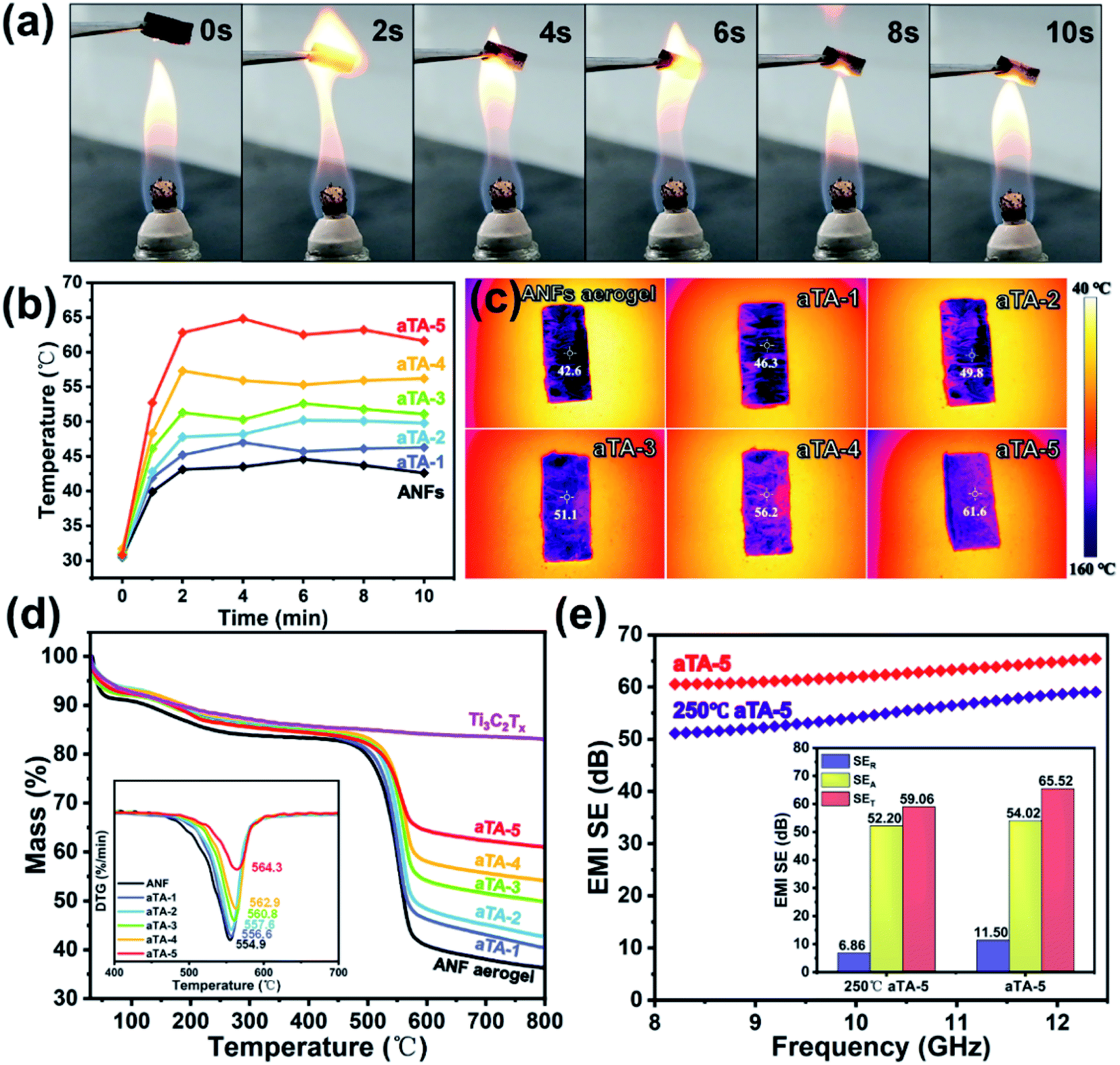 | ||
| Fig. 7 (a) Photographs of aTA-5 in the flame of an alcohol burner. (b) Temperature–time curves of the ANF aerogel, aTA-1, aTA-2, aTA-3, aTA-4, aTA-5 and Ti3C2Tx. (c) A series of infrared thermal imager photos of the Ti3C2Tx/ANF composite aerogels placed on a heating table at 150 °C. (d) TGA and DTA curves of a series of MXene/ANF composite aerogels. (e) EMI SE, SET, SEA and SER of aTA-5 before and after treatment at 250 °C for 2 hours. | ||
In addition, to explore the effect of high temperature on the shielding performance of the composite aerogels, aTA-5 was placed in an air atmosphere in a tube furnace at 250 °C for 2 h, and the performance changes were compared before and after. Fig. 7e shows the comparison of the shielding performance in the X-band and the specific values of SET, SER, and SEA at 12.4 GHz. Thanks to the protection of the MXene edge by the ANFs, the EMI SE of the composite aerogels in the harsh environment of high temperature, up to 59.1 dB at 12.4 GHz, was still outstanding. The decline of SER was a key factor in the decline of the shielding performance. Since aTA-5 aggravated the oxidation of MXene in high-temperature air, the Ti–C bond converted to a Ti–O bond, and the conductive network was damaged to a certain extent, thereby reducing the conductivity and SER. Interestingly, SEA only dropped slightly, which may be due to the oxidation of the MXene surface to produce many TiO2 sites. Because of the strong impedance mismatch between MXene and TiO2, more interface polarization was formed, causing TiO2 to become an excellent microwave absorber.29,39,41 Obviously, aTA-5 at 250 °C exhibited more degradation at a lower frequency. It may be explained that the shielding material conductive network was damaged, and the shielding performance decreased significantly in the lower frequency band with strong reflection dependence, while maintaining a high level of shielding performance in the high frequency band with strong absorption dependence.42 This further demonstrated the excellent thermal stability of the anisotropic Ti3C2Tx/ANF aerogel, which has promising applications in the aerospace and metallurgical industries, such as electromagnetic shielding components in aircraft engine casings, and communication needs in the metallurgical industry.
Conclusions
In summary, we demonstrated a method to improve the shielding performance of aerogels by constructing an anisotropic structure. Based on the hydrogen bonds and van der Waals forces between the Ti3C2Tx nanosheets and ANFs, a Ti3C2Tx/ANF anisotropic aerogel with a rigid skeleton and “cell wall” structure was constructed by directional freezing and freeze-drying. Based on its structural design, the aerogel achieved outstanding compressive strength (93.59 kPa) and superelasticity. The highly ordered porous structure forced the Ti3C2Tx nanosheets to form continuous conductive paths, thus increasing the sites of impedance mismatch and conductive loss. In addition, the “cell wall” structure introduced more interfaces with ANFs, which further attenuated EMWs depending on the interface polarization effect. Based on the synergistic effect, the anisotropic aerogel achieved a high conductivity of 854.9 S m−1 and an excellent EMI SE of 65.5 dB at an ultra-low conductive filler content (0.58 vol%). Meanwhile, the ultra-low density of 23.3 mg cm−3 and high SSE/t of 11391 dB cm2 g−1 made our composite aerogel stand out from other shielding materials. In addition, the composite aerogel exhibited excellent flame retardant and thermal insulation properties without any damage phenomenon under fire. The shielding efficiency of the composite aerogel was 59.1 dB when the device was incubated at 250 °C for 2 h. The anisotropic Ti3C2Tx/ANF aerogel has excellent comprehensive properties, such as superelasticity, high shielding performance, excellent flame retardance, and thermal stability dependent on the oriented structure. It has great application prospects in fields such as aerospace and the military where shielding devices need to work stably under extreme conditions.
Conflicts of interest
There are no conflicts to declare.Acknowledgements
This work was supported by the National Natural Science Foundation of China (52073091, 51773060, 51573045, 22171086) and the Natural Science Foundation of Shanghai (20ZR1414600).Notes and references
- A. Iqbal, P. Sambyal and C. M. Koo, Adv. Funct. Mater., 2020, 30, 2000883 CrossRef CAS.
- J. Liu, H. B. Zhang, R. Sun, Y. Liu, Z. Liu, A. Zhou and Z. Z. Yu, Adv. Mater., 2017, 29, 1702367 CrossRef PubMed.
- Y. Cheng, X. Li, Y. Qin, Y. Fang, G. Liu, Z. Wang, J. Matz, P. Dong, J. Shen and M. Ye, Sci. Adv., 2021, 7, eabj1663 CrossRef CAS PubMed.
- W. J. Ma, P. He, T. Y. Wang, J. Xu, X. Y. Liu, Q. X. Zhuang, Z. K. Cui and S. L. Lin, Chem. Eng. J., 2021, 420, 129875 CrossRef CAS.
- L. Liang, Q. Li, X. Yan, Y. Feng, Y. Wang, H. B. Zhang, X. Zhou, C. Liu, C. Shen and X. Xie, ACS Nano, 2021, 15, 6622–6632 CrossRef CAS PubMed.
- F. Shahzad, M. Alhabeb, C. B. Hatter, B. Anasori, S. Man Hong, C. M. Koo and Y. Gogotsi, Science, 2016, 353, 1137–1140 CrossRef CAS PubMed.
- Y. Wan, P. Xiong, J. Liu, F. Feng, X. Xun, F. M. Gama, Q. Zhang, F. Yao, Z. Yang, H. Luo and Y. Xu, ACS Nano, 2021, 15, 8439–8449 CrossRef CAS PubMed.
- X. Wu, T. Tu, Y. Dai, P. Tang, Y. Zhang, Z. Deng, L. Li, H. B. Zhang and Z. Z. Yu, Nano-Micro Lett., 2021, 13, 148 CrossRef CAS PubMed.
- W. Chen, L. X. Liu, H. B. Zhang and Z. Z. Yu, ACS Nano, 2021, 15, 7668–7681 CrossRef CAS PubMed.
- Z. Liu, Y. Zhang, H.-B. Zhang, Y. Dai, J. Liu, X. Li and Z.-Z. Yu, J. Mater. Chem. C, 2020, 8, 1673–1678 RSC.
- K. Maleski, V. N. Mochalin and Y. Gogotsi, Chem. Mater., 2017, 29, 1632–1640 CrossRef CAS.
- W. Bao, X. Tang, X. Guo, S. Choi, C. Wang, Y. Gogotsi and G. Wang, Joule, 2018, 2, 778–787 CrossRef CAS.
- M. Q. Zhao, X. Xie, C. E. Ren, T. Makaryan, B. Anasori, G. Wang and Y. Gogotsi, Adv. Mater., 2017, 29, 1702410 CrossRef PubMed.
- X. Zhang, R. Lv, A. Wang, W. Guo, X. Liu and J. Luo, Angew. Chem., Int. Ed., 2018, 57, 15028–15033 CrossRef CAS PubMed.
- C. Xing, S. Chen, X. Liang, Q. Liu, M. Qu, Q. Zou, J. Li, H. Tan, L. Liu, D. Fan and H. Zhang, ACS Appl. Mater. Interfaces, 2018, 10, 27631–27643 CrossRef CAS PubMed.
- Y. Yue, N. Liu, W. Liu, M. Li, Y. Ma, C. Luo, S. Wang, J. Rao, X. Hu, J. Su, Z. Zhang, Q. Huang and Y. Gao, Nano Energy, 2018, 50, 79–87 CrossRef CAS.
- J. Liu, H. B. Zhang, X. Xie, R. Yang, Z. Liu, Y. Liu and Z. Z. Yu, Small, 2018, 14, e1802479 CrossRef PubMed.
- Z. Ma, S. Kang, J. Ma, L. Shao, Y. Zhang, C. Liu, A. Wei, X. Xiang, L. Wei and J. Gu, ACS Nano, 2020, 14, 8368–8382 CrossRef CAS PubMed.
- L. Liang, C. Yao, X. Yan, Y. Feng, X. Hao, B. Zhou, Y. Wang, J. Ma, C. Liu and C. Shen, J. Mater. Chem. A, 2021, 9, 24560–24570 RSC.
- W. T. Cao, F. F. Chen, Y. J. Zhu, Y. G. Zhang, Y. Y. Jiang, M. G. Ma and F. Chen, ACS Nano, 2018, 12, 4583–4593 CrossRef CAS PubMed.
- B. Yang, L. Wang, M. Zhang, J. Luo, Z. Lu and X. Ding, Adv. Funct. Mater., 2020, 30, 2000186 CrossRef CAS.
- R. Bian, G. He, W. Zhi, S. Xiang, T. Wang and D. Cai, J. Mater. Chem. C, 2019, 7, 474–478 RSC.
- M. Yang, K. Cao, L. Sui, Y. Qi, J. Zhu, A. Waas, E. M. Arruda, J. Kieffer, M. D. Thouless and N. A. Kotov, ACS Nano, 2011, 5, 6945–6954 CrossRef CAS PubMed.
- J.-Q. Luo, S. Zhao, H.-B. Zhang, Z. Deng, L. Li and Z.-Z. Yu, Compos. Sci. Technol., 2019, 182, 107754 CrossRef CAS.
- A. Sarycheva and Y. Gogotsi, Chem. Mater., 2020, 32, 3480–3488 CrossRef CAS.
- H. Xu, X. Yin, X. Li, M. Li, S. Liang, L. Zhang and L. Cheng, ACS Appl. Mater. Interfaces, 2019, 11, 10198–10207 CrossRef CAS PubMed.
- T. Hu, J. Wang, H. Zhang, Z. Li, M. Hu and X. Wang, Phys. Chem. Chem. Phys., 2015, 17, 9997–10003 RSC.
- M. Han, X. Yin, H. Wu, Z. Hou, C. Song, X. Li, L. Zhang and L. Cheng, ACS Appl. Mater. Interfaces, 2016, 8, 21011–21019 CrossRef CAS PubMed.
- A. Iqbal, F. Shahzad, K. Hantanasirisakul, M.-K. Kim, J. Kwon, J. Hong, H. Kim, D. Kim, Y. Gogotsi and C. M. Koo, Science, 2020, 369, 446–450 CrossRef CAS PubMed.
- M. Han, X. Yin, K. Hantanasirisakul, X. Li, A. Iqbal, C. B. Hatter, B. Anasori, C. M. Koo, T. Torita, Y. Soda, L. Zhang, L. Cheng and Y. Gogotsi, Adv. Opt. Mater., 2019, 7, 1900267 CrossRef.
- Z. Lu, F. Jia, L. Zhuo, D. Ning, K. Gao and F. Xie, Composites, Part B, 2021, 217, 108853 CrossRef CAS.
- B. Zhao, M. Hamidinejad, S. Wang, P. Bai, R. Che, R. Zhang and C. B. Park, J. Mater. Chem. A, 2021, 9, 8896–8949 RSC.
- H. Liu, S. Wu, C. You, N. Tian, Y. Li and N. Chopra, Carbon, 2021, 172, 569–596 CrossRef CAS.
- P. Hu, J. Lyu, C. Fu, W. B. Gong, J. Liao, W. Lu, Y. Chen and X. Zhang, ACS Nano, 2020, 14, 688–697 CrossRef CAS PubMed.
- Z. Yu, T. Dai, S. Yuan, H. Zou and P. Liu, ACS Appl. Mater. Interfaces, 2020, 12, 30990–31001 CrossRef CAS PubMed.
- M. Wang, X.-H. Tang, J.-H. Cai, H. Wu, J.-B. Shen and S.-Y. Guo, Carbon, 2021, 177, 377–402 CrossRef CAS.
- Y. Wang, H.-K. Peng, T.-T. Li, B.-C. Shiu, H.-T. Ren, X. Zhang, C.-W. Lou and J.-H. Lin, Chem. Eng. J., 2021, 412, 128681 CrossRef CAS.
- P. Sambyal, A. Iqbal, J. Hong, H. Kim, M. K. Kim, S. M. Hong, M. Han, Y. Gogotsi and C. M. Koo, ACS Appl. Mater. Interfaces, 2019, 11, 38046–38054 CrossRef CAS PubMed.
- S. Li, J. Wang, Z. Zhu, D. Liu, W. Li, G. Sui and C. B. Park, J. Mater. Chem. A, 2021, 9, 358–370 RSC.
- Z. Deng, P. Tang, X. Wu, H. B. Zhang and Z. Z. Yu, ACS Appl. Mater. Interfaces, 2021, 13, 20539–20547 CrossRef CAS PubMed.
- G. Zhao, H. Lv, Y. Zhou, X. Zheng, C. Wu and C. Xu, ACS Appl. Mater. Interfaces, 2018, 10, 42925–42932 CrossRef CAS PubMed.
- F. Song, G. Li, Y. Zhu, Z. Wu, X. Xie and N. Zhang, J. Mater. Chem. A, 2020, 8, 18538–18559 RSC.
Footnote |
| † Electronic supplementary information (ESI) available. See DOI: 10.1039/d1ta11025j |
| This journal is © The Royal Society of Chemistry 2022 |