Surface engineering of anode materials for improving sodium-ion storage performance
Qingbing
Xia
 ,
Hanwen
Liu
and
Xiu Song
Zhao
 *
*
School of Chemical Engineering, The University of Queensland, St Lucia, QLD 4072, Australia. E-mail: george.zhao@uq.edu.au
First published on 24th January 2022
Abstract
Sodium-ion batteries (NIBs) are considered a complementary or even an alternative energy storage technology to lithium-ion batteries (LIBs). Current technological development of NIBs is hindered by fundamental challenges, such as sluggish charge transport kinetics, short cycling lifespan, and low energy density. Electrode materials hold the key to any success in commercialising NIBs. While the past decade has witnessed rapid advances in design and synthesis of various electrode materials with different structures and microcosmic morphologies, there are still critical issues associated with electrode materials, especially anode materials, that need to be addressed before the NIB technology becomes commercially viable. For battery electrode materials, their surface properties play a critical role in determining cell performance. As a forefront of an electrode material where Na ion storage and charge transfer initiate, the electrode surface has a fundamental influence on the charge storage properties of the electrode. In this article, we review recent research progress towards modification/functionalisation of the surface structure of NIB anode materials for improving charge transport kinetics, charge storage capacity, and cycling durability. We aim to provide a concise summary of strategies for surface engineering, along with an insightful analysis of the critical role of the surface structure of NIB anode materials in determining their electrochemical performance.
1. Introduction
With the fast growing market of portable electronic devices, electric vehicles, and grid energy storage, the demand for energy storage devices, like rechargeable batteries, has been drastically increasing. Lithium-ion batteries (LIBs) have profound impact on our daily life because of their high energy and power density coupled with long lifespan.1–5 However, LIBs are facing severe challenges because lithium resources are geographically unevenly distributed and limited on Earth.5–8 It is reported that there are only some 14.3 Mt of lithium reserves, of which more than 60% of the accessible lithium resources is in remote or politically sensitive areas.7,8 Therefore, sustainable battery technologies have been widely explored.9 Sodium-ion batteries (NIBs) with a similar working principle to that of LIBs have received considerable interest from both academics and industry.8–11 Sodium is abundant in nature and cost-effective. Thus, NIBs are considered to be a sustainable energy storage technology.7,10–12 Sodium has a redox potential of −2.71 V vs. the standard hydrogen electrode, slightly lower than that of lithium (−3.01 V for lithium vs. the standard hydrogen electrode).10,11,13 The fundamental knowledge on LIBs can be adopted in the NIB chemistry. However, the larger atomic radius of Na+ (1.02 Å) than Li+ (0.76 Å) along with the heavier atomic mass are the disadvantages of NIBs in terms of charge transport kinetics and gravimetric energy density when compared with LIBs.10–12Electrode materials hold the key in determining the battery performance. Cathode materials for NIBs have been extensively investigated over the past decade,14,15 such as transition-metal layered oxides,16–18 polyanionic phosphate compounds,19–21 and Prussian blue phases,22–24 and some of them can reach a battery performance comparable to that of commercial LIBs with LiFePO4 as the cathode.8,15 Nevertheless, there are still fundamental challenges such as low coulombic efficiency, severe phase transition, metal ion dissolution, and sluggish charge transport kinetics that need to be solved. On the anode side, carbon,25–27 metals/alloys,28–32 and metal oxides/sulphides/phosphides13,33–41 are all promising for NIBs. For example, hard carbon materials can deliver a reversible capacity of more than 400 mA h g−1 with a Na+ insertion voltage plateau at about 0.1 V (vs. Na+/Na).25,42 Sluggish sodiation kinetics is a challenging issue for the anode materials. This mainly originates from their intrinsic low electronic/ionic conductivity and/or multi-step phase change mechanisms during charge/discharge. Besides, large volume change is another crucial issue for many alloying-type and conversion-type anode materials, particularly for phosphorus and transition metal sulphides/phosphides.43,44 Red phosphorus with a theoretical capacity of ∼2600 mA h g−1 suffers from a volume expansion of up to ∼400% after full sodiation to form Na3P.13 Strategies such as using nanotechnology to shorten Na ion diffusion pathways,29,30,33,36 supporting electroactive materials on an electron-conductive support to improve electronic conductivity,44,45 and heteroatom doping to enhance charge mobility34,46 are often used to improve electrode performance.
The surface properties of an electrode material play a paramount role in determining the electrode performance. For crystalline materials, their structural symmetry is changed from three-dimensional (3D) in the bulk to two-dimensional (2D) on the surface. Such a discontinuity of the structural order will lead to an energy barrier change for charge transport.47 Besides, side reactions between the electrode and electrolyte, phase transformation, and volume expansion also bring in changes of structural integrity and chemical/physical properties of the electrode surface, influencing the electrochemical performance. Therefore, the surface properties of electrode materials have significant impacts on charge transport kinetics, charge storage capacity and reversibility, coulombic efficiency, solid electrolyte interphase (SEI), structural integrity, and cycling stability. Recently, surface engineering of electrode materials has become an extremely important solution to improve electrode performance.34,47–49
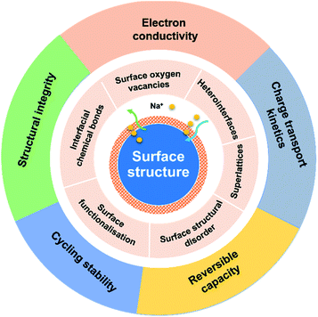
Surface engineering of electrode materials for LIBs,47,50,51 lithium metal batteries,52 zinc-ion batteries,53 or aqueous supercapacitors54 has been published. However, there is no review on surface engineering of anode materials for NIBs. As illustrated in Fig. 1, the present review summarises recent research progress on strategies for surface modification of NIB anode materials to improve charge transport kinetics, rate capability, charge storage capacity, and cycling stability. Recent review articles on interfacial chemistry in NIBs have been published and are suggested to be read.55–58
2. Surface oxygen vacancies (OVs)
Metal oxides, such as titanium dioxide (TiO2),59–63 tin dioxide (SnO2),64,65 vanadium oxide (V2O5),66 and sodium titanate (Na2Ti3O7)67,68 are promising anode candidates for NIBs. For example, TiO2 has merits of excellent cycling stability and low cost.69–72 However, the metal oxides suffer from poor rate capability and sluggish sodiation kinetics, originating from their intrinsic semiconducting nature.34,69,70,73Oxygen vacancies (OVs) are present in many metal oxides as point defects. OVs are formed due to the absence of oxygen ions in the crystal lattice as schematically illustrated in Fig. 2a. The presence of OVs changes the local coordination adjacent to them without alternating the intrinsic lattice periodicity, thus altering the local charge distribution and electronic energy levels near the OV site. Introduction of OVs on the surface of metal oxides can significantly enhance electronic conductivity and lower the sodiation energy barrier to facilitate Na ion intercalation and migration kinetics, achieving enhanced charge transport kinetics.59,74 The typical OV fabrication methods include treatment using a reductant (e.g., NaHB4 or urea)61,63,67 or in a reductive atmosphere (e.g., H2),68 and carbothermal reduction.65
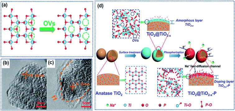 | ||
| Fig. 2 Surface oxygen vacancies in TiO2: (a) schematic illustration of formation of OVs due to loss of oxygen atoms, (b and c) TEM images of defect-free and defective TiO2 with surface OVs,63 copyright 2016, American Chemical Society. (d) Schematic illustration of surface OV-induced doping of phosphorus (P).61 Copyright 2019, American Chemical Society. | ||
Ji and co-workers employed NaBH4 as a reductant to treat anatase to introduce surface OVs into TiO2.63 The TiO2 precursor was ground with NaHB4 in a mass ratio of 2![[thin space (1/6-em)]](https://www.rsc.org/images/entities/char_2009.gif) :
:![[thin space (1/6-em)]](https://www.rsc.org/images/entities/char_2009.gif) 1 to get a uniform mixture, which was heated at 350 °C for 2 h in an Ar atmosphere. Transmission electron microscopy (TEM) images showed a thin layer consisting of OVs and disordered Ti2O3 on the surface of modified TiO2 (Fig. 2b and c). Computational calculations revealed a narrow band gap and reduced energy barriers (5.63 eV in OV-free TiO2vs. 4.75 eV in OV-containing TiO2) for Na ion intercalation in the OV-modified TiO2, indicating enhancement of electron conductivity. Although enhanced electrochemical performance can be achieved, it's hard to control the OV concentration by using the NaHB4 reductant. Thermal annealing of the TiO2 nanotubes in a N2 atmosphere could realize the controllability of OVs by tuning the annealing temperature.62 It is found that a sample synthesized at 600 °C showed the highest surface OV concentration in the TiO2 nanotubes and delivered the best Na ion storage performance. The presence of OVs also effectively enhanced the electronic conductivity and reduced the Na ion insertion energy barrier. Kinetic analysis revealed that the Na ion storage proceeded via a pseudocapacitive mechanism, and the charge storage capacity dramatically increased with increasing OV concentration. However, such an OV preparation method involved a high temperature-treatment process, which makes it difficult to apply to the oxide anodes with nanoarchitectures. Gan et al. developed a defect-assisted phosphorus doping strategy to selectively engineer the surface of TiO2 particles to fabricate a TiO2@TiO2−x–P core@shell architecture.61 The pinecone-like TiO2 was first treated by using NaBH4 to generate abundant OVs in the surface region (denoted as TiO2@TiO2−x). Then TiO@TiO2−x was further subjected to a phosphorization process by using NaH2PO2 as the P-source at 300 °C, resulting in the brown-black TiO2@TiO2−x–P powder. The core was well crystalline TiO2, while the shell consisted of amorphous TiO2−x–P of thickness between 4 and 6 nm and was rich in OVs and Ti3+ species (Fig. 2d). The high-resolution TEM (HRTEM) images and the electron paramagnetic resonance (EPR) spectra revealed the existence of OVs, Ti3+ species, and the P dopant in the shell, which greatly improved the local electronic conductivity from 4.21 × 10⁻⁷ S cm−1 (TiO2) to 2.76 × 10⁻⁶ S cm−1 (TiO2@TiO2−x–P) and decreased the Na ion intercalation energy barrier. The oxygen-vacant surface structure acted as a highway for ultrafast electron transport and a buffered zone to efficiently facilitate Na ion interchange between the electrolyte and the bulk of the TiO2 particles, resulting in a promising rate capability with a specific capacity of 167 mA h g−1 at 10 A g−1 and stable cycling stability with a capacity retention of 98.9% up to 5000 cycles at the same current density. Nevertheless, the synthetic process for TiO2@TiO2−x–P involved the utilization of highly toxic phosphine.
1 to get a uniform mixture, which was heated at 350 °C for 2 h in an Ar atmosphere. Transmission electron microscopy (TEM) images showed a thin layer consisting of OVs and disordered Ti2O3 on the surface of modified TiO2 (Fig. 2b and c). Computational calculations revealed a narrow band gap and reduced energy barriers (5.63 eV in OV-free TiO2vs. 4.75 eV in OV-containing TiO2) for Na ion intercalation in the OV-modified TiO2, indicating enhancement of electron conductivity. Although enhanced electrochemical performance can be achieved, it's hard to control the OV concentration by using the NaHB4 reductant. Thermal annealing of the TiO2 nanotubes in a N2 atmosphere could realize the controllability of OVs by tuning the annealing temperature.62 It is found that a sample synthesized at 600 °C showed the highest surface OV concentration in the TiO2 nanotubes and delivered the best Na ion storage performance. The presence of OVs also effectively enhanced the electronic conductivity and reduced the Na ion insertion energy barrier. Kinetic analysis revealed that the Na ion storage proceeded via a pseudocapacitive mechanism, and the charge storage capacity dramatically increased with increasing OV concentration. However, such an OV preparation method involved a high temperature-treatment process, which makes it difficult to apply to the oxide anodes with nanoarchitectures. Gan et al. developed a defect-assisted phosphorus doping strategy to selectively engineer the surface of TiO2 particles to fabricate a TiO2@TiO2−x–P core@shell architecture.61 The pinecone-like TiO2 was first treated by using NaBH4 to generate abundant OVs in the surface region (denoted as TiO2@TiO2−x). Then TiO@TiO2−x was further subjected to a phosphorization process by using NaH2PO2 as the P-source at 300 °C, resulting in the brown-black TiO2@TiO2−x–P powder. The core was well crystalline TiO2, while the shell consisted of amorphous TiO2−x–P of thickness between 4 and 6 nm and was rich in OVs and Ti3+ species (Fig. 2d). The high-resolution TEM (HRTEM) images and the electron paramagnetic resonance (EPR) spectra revealed the existence of OVs, Ti3+ species, and the P dopant in the shell, which greatly improved the local electronic conductivity from 4.21 × 10⁻⁷ S cm−1 (TiO2) to 2.76 × 10⁻⁶ S cm−1 (TiO2@TiO2−x–P) and decreased the Na ion intercalation energy barrier. The oxygen-vacant surface structure acted as a highway for ultrafast electron transport and a buffered zone to efficiently facilitate Na ion interchange between the electrolyte and the bulk of the TiO2 particles, resulting in a promising rate capability with a specific capacity of 167 mA h g−1 at 10 A g−1 and stable cycling stability with a capacity retention of 98.9% up to 5000 cycles at the same current density. Nevertheless, the synthetic process for TiO2@TiO2−x–P involved the utilization of highly toxic phosphine.
Apart from TiO2 anodes, the surface oxygen vacancies have also shown great success in improving the performance of SnO2 anodes. SnO2 with a high theoretical Na ion storage capacity of 1398 mA h g−1 holds great promise for NIBs.73,75 However, the electrochemical performance of SnO2 is greatly hindered by its sluggish sodiation kinetics. The creation of surface OVs has proved to be an effective route to regulate the Na ion intercalation/de-intercalation kinetics of SnO2 anode materials.64 Ma et al. described the preparation of a composite anode material consisting of SnO2−x nanoparticles confined in porous carbon nanofibers (SnO2−x/C) by using the electrospinning technique (Fig. 3a).65 During the high temperature calcination process, the SnO2 crystals were partially reduced to OVs containing-SnO2−x through the carbonthermal reduction (Fig. 3b and c). The experimental results confirmed that the introduction of OVs effectively enhanced the electronic conductivity of SnO2−x crystals and improved the stability of the interface between discharged products of Sn and Na2O. Besides, the porous carbon nanofibers provided space for buffering the volume changes of the confined SnO2−x nanocrystals. The SnO2−x/C composite electrode exhibited a remarkably enhanced sodiation kinetics and reversibility of conversion reaction Sn ↔ SnO2−x (Fig. 3d). It delivered a discharge capacity of 565 mA h g−1 at 1 A g−1 after 2000 cycles.
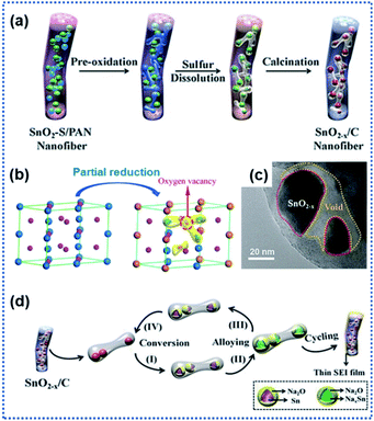 | ||
| Fig. 3 Surface oxygen vacancies for improving charge transport kinetics of SnO2: (a) schematic illustration of the preparation of SnO2−x/C nanofibers, (b) illustration of structural transformation from SnO2 to SnO2−x, (c) TEM image of SnO2−x/C, and (d) illustration of Na ion intercalation/deintercalation mechanisms in SnO2−x/C.65 Copyright 2018, Wiley-VCH. | ||
Na2Ti3O7 has an average discharging voltage of 0.3 V vs. Na+/Na and a theoretical Na ion storage capacity of 310 mA h g−1.70,72,76,77 However, like other metal oxide anode materials, Na2Ti3O7 also suffers from sluggish Na insertion/extraction kinetics. Surface OV modulation is a useful approach for facilitating the sodiation kinetics of Na2Ti3O7. Fu et al. synthesized Na2Ti3O7 nanoarrays by hydrothermally treating Ti foil in NaOH aqueous solution (Fig. 4a).68 During the following thermal treatment in an Ar/H2 atmosphere at 450 °C for 2 h, a crystal structure disordered layer with OVs was formed on the surface of the Na2Ti3O7 nanotubes (designated as H–Na2Ti3O7, Fig. 4b). The formation of OVs along with Ti3+ in the surface layer (Fig. 4c) dramatically enhanced the electrical conductivity from 1.7 × 10⁻⁷ S cm−1 for air treated Na2Ti3O7 (designated as A–Na2Ti3O7) to 1.2 × 10⁻⁴ S cm−1 (H–Na2Ti3O7). Meanwhile, the OVs enabled H–Na2Ti3O7 to possess a 5-fold higher carrier density than A–Na2Ti3O7, drastically reducing the charge transport resistance. H–Na2Ti3O7 afforded a high cycling stability of over 10![[thin space (1/6-em)]](https://www.rsc.org/images/entities/char_2009.gif) 000 cycles without obvious capacity fading at 35C. Costa et al. used urea as the reducing agent to form OVs on the surface of Na2Ti3O7 particles.67 At high temperature, urea decomposes into ammonia which further decomposes to produce reactive H2 that removes oxygen from the Na2Ti3O7 structure, forming surface OV decorated Na2Ti3O7. It was found that the concentration of OVs could be controlled by controlling the concentration of urea. The introduction of OVs triggered the formation of Ti3+ and Ti–OH species, along with a new phase, Na2Ti6O13 (Fig. 4d). Ab initio calculations revealed that the presence of OVs leads to electrons from the OVs to be centered on Ti cations and the reduction of Ti4+ to Ti3+, resulting in a decrease in the bandgap energy of Na2Ti3O7 and an increase in electronic conductivity. The 20 wt% urea sample showed the best electrochemical performance with discharge capacities of 316 mA h g−1 at 1C and 272 mA h g−1 at 2C. The improved electrochemical performance is attributed to the enhancement of Na ion diffusivity, enhanced charge carrier density, and reduced bandgap energy, which all originate from the surface OVs.
000 cycles without obvious capacity fading at 35C. Costa et al. used urea as the reducing agent to form OVs on the surface of Na2Ti3O7 particles.67 At high temperature, urea decomposes into ammonia which further decomposes to produce reactive H2 that removes oxygen from the Na2Ti3O7 structure, forming surface OV decorated Na2Ti3O7. It was found that the concentration of OVs could be controlled by controlling the concentration of urea. The introduction of OVs triggered the formation of Ti3+ and Ti–OH species, along with a new phase, Na2Ti6O13 (Fig. 4d). Ab initio calculations revealed that the presence of OVs leads to electrons from the OVs to be centered on Ti cations and the reduction of Ti4+ to Ti3+, resulting in a decrease in the bandgap energy of Na2Ti3O7 and an increase in electronic conductivity. The 20 wt% urea sample showed the best electrochemical performance with discharge capacities of 316 mA h g−1 at 1C and 272 mA h g−1 at 2C. The improved electrochemical performance is attributed to the enhancement of Na ion diffusivity, enhanced charge carrier density, and reduced bandgap energy, which all originate from the surface OVs.
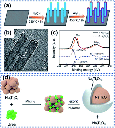 | ||
| Fig. 4 Examples of creating surface oxygen vacancies in Na2Ti3O7: (a) schematic illustration of the preparation of hydrogen-reduced Na2Ti3O7 (H–Na2Ti3O7), (b) TEM image of H–Na2Ti3O7, and (c) Ti 2p XPS spectra of air-treated Na2Ti3O7 (A–Na2Ti3O7) and H–Na2Ti3O7 (the blue dashed line represents the difference between the two XPS spectra).68 Copyright 2016, American Chemical Society. (d) Schematic illustration of formation of surface OVs on Na2Ti3O7 by reaction with urea in a nitrogen atmosphere at 450 °C.67 Copyright 2021, Wiley-VCH. | ||
In summary, the surface OV engineering strategy enables one to alter the charge distribution and electronic energy levels of metal oxide anode materials to improve their sodiation kinetics and rate capability. Surface OVs are commonly generated by using the chemical reduction method to remove part of lattice oxygen ions in the metal oxide. Control over the concentration and the distribution uniformity of OVs is a great challenge. Besides, Na ion interaction behavior with the vacancies has not been fully understood. In addition, structural stability of the oxygen-vacant surface during continuous cycling needs to be studied. The core of OVs is used to construct O site defects, and such an anion site engineering conception can be extended to metal sulfides and selenides to construct S or Se vacancies, improving the structural properties.
3. Heterointerfaces
A heterointerface is formed between two dissimilar crystalline materials through lattice-matching, such as between Sb2S3 and SnS2,78 SnS2 and SnO2,75 Bi2S3 and MoS2,79 CoSe2 and ZnSe,80 Fe2Se4 and FeSe,81 Cu2P7 and CuP2,82 tetragonal SnO2 and orthorhombic SnO2,83 Co3O4–CoO,84 and VO/V2O3.66 The heterointerface between the two crystalline phases can generate a synergistic effect, which is favorable for improving the electrochemical performance of the electrode materials.79,85–88 At the heterointerface, the Fermi energy difference between the two phases leads to electron transfer across the interface, creating a built-in electric field to induce charge redistribution as schematically illustrated in Fig. 5a. The intrinsic electroneutral phases around the heterointerface are ionized to carry positive charges or negative charges, which can act as active sites for electrochemical reactions and adsorption of opposite charges.49,89–92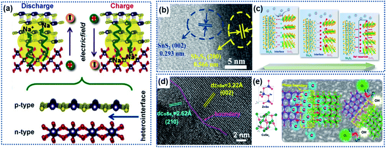 | ||
| Fig. 5 Heterointerface-induced built-in electric field: (a) schematic illustration of the formation of a built-in electric field due to a heterointerface.75 Copyright 2016, Wiley-VCH. (b) High-resolution TEM (HRTEM) image showing the interface formed between Sb2S3 and SnS2. (c) Illustration of the charge storage mechanism induced by the Sb2S3–SnS2 heterointerface.78 Copyright 2019, Elsevier. (d) HRTEM image and (e) schematic illustration of the CoZn–Se heterointerface.80 Copyright 2020, American Chemical Society. | ||
Fang et al. developed a Sb2S3–SnS2 hetero-nanostructure using a pulsed-spray evaporation chemical vapor deposition technique to enhance the conversion reaction kinetics (Fig. 5b).78 DFT calculations showed that the Sb2S3 phase had a lower bandgap energy (1.72 eV) than the SnS2 phase (2.10 eV). The heterointerface resulted in the Fermi energy shifting towards the lower-level potential for the Sb2S3 phase and higher-level potential for the SnS2 phase, respectively, creating an internal electric field pointing from the Sb2S3 phase to the SnS2 phase. Na ions were strongly attracted to the SnS2 phase side to reach charge balance until the interfacial electric field disappears. Then, the Na ions migrated to both phases driven by the ion concentration gradient across the heterointerface, achieving a superior conversion reaction kinetics (Fig. 5c). In this work, the Sb2S3–SnS2 heterointerface only achieved 94% capacity retention after 50 cycles. However, both Sb2S2 and SnS2 undergo large volume change upon insertion of Na ions, which may destroy the structural integrity of the Sb2S3–SnS2 heterointerface. Similarly, the heterointerface between CoSe2 and ZnSe provided a much lower Na ion adsorption energy due to the electron redistribution along the phase boundary (Fig. 5d and e).80 Theoretical calculations revealed that the band gap difference between the two phases produces a strong electrostatic field across the interface, driving electrons to migrate from the CoSe2 side to the ZnSe side to accumulate in ZnSe. The electron accumulation leads to strong attraction of Na ions on the phase boundary close to the ZnSe side, thus enabling fast intercalation kinetics.
Local transformation of a primary phase into a secondary phase also leads to the formation of heterointerfaces.81–84,87 Usually, the two phases are composed of the same elements with a good lattice match. For example, Liu and co-workers reported Fe3Se4/FeSe heterointerfaces synthesized via a gas-phase selenisation method (Fig. 6a).81 The DFT calculation results showed that the Fe3Se4/FeSe heterostructure was in a metallic state with a high carrier density near the Fermi level. The charge accumulation occurred not only at the Fe3Se4/FeSe heterointerface but also around the Fe atoms to facilitate efficient charge transfer (Fig. 6b), thus enhancing electronic conductivity. Another example is the heterointerface in a Cu2P7/CuP2/C composite material prepared by using the ball milling method, in which carbon was used as a conductive matrix to support the Cu2P7/CuP2 heterostructure.82 The band gap difference between Cu2P7 and CuP2 enabled the heterointerfaces to not only exhibit more favorable ion/electron transportation but also more electrochemical active sites.
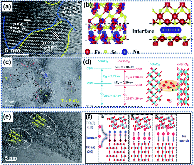 | ||
| Fig. 6 Roles of heterointerfaces in facilitating efficient charge transport: (a) HRTEM image showing the heterointerface between Fe3Se4 and FeSe, (b) schematic illustration of the charge density distribution (left) and Na ion migration pathway (right) along the Fe3Se4/FeSe heterointerface.81 Copyright 2021, Elsevier. (c) HRTRM image showing the presence of multiple heterointerfaces in a SnO2/Se/graphene composite. (d) Illustration of band alignments of t-SnO2 and o-SnO2 at the heterointerface generating an electric field to accelerate charge transport.83 Copyright 2018, Royal Society of Chemistry. (e) HRTEM image showing the presence of two TiO2 phases forming a heterointerface. (f) Schematic illustration of the role of the anatase/TiO2(B) heterointerface as an ion reservoir for Li+/Na+ storage.87 Copyright 2018, Royal Society of Chemistry. | ||
Wang et al. fabricated multiple heterointerfaces, including tetragonal and orthorhombic SnO2 (t-/o-SnO2) heterointerfaces and t/o-SnO2 and the two-phase heterointerfaces between t/o-SnO2 and a-Se (Fig. 6c), by introducing Se into SnO2 nanoparticles.83 The electron flow from the t-SnO2 phase to the o-SnO2 phase resulted in multiple built-in electric fields at the heterointerfaces, which significantly boosted the interface sodiation kinetics to realize ultrafast Na ion storage (Fig. 6d). Similarly, the anatase/TiO2 (B) heterointerface ensured an internal electric field with a high ionic concentration to facilitate the fast charge transport and a low Na ion adsorption energy, giving rise to fast electrochemical kinetics (Fig. 6e and f).87
In summary, the unique characteristics of the heterointerface existing in two-phase materials, including built-in electric field, local charge accumulation, and Fermi energy shift, that are not observed in single-phase materials can effectively enhance sodiation reaction kinetics, resulting in a significantly improved rate capability. The lattice strain around the heterointerface will have a critical impact on the stability of the heterointerface, which needs to be investigated. Alloying-type anode materials, such as SnS2, Sb2S3 and FeSe experience drastic phase changes and large volume expansion during cycling, potentially destroying the stability of the heterointerface. Research work is needed to improve the heterointerface stability.
4. Superlattices
2D superlattices consist of alternately stacked 2D monolayer nanosheets at atomic/molecular levels (Fig. 7a). Monolayer graphene sheets are often used as one of the components to fabricate 2D superlattices for improving electron conductivity.33,35,46,93–96 The high-quality periodic alternate stacking of the single layers results in an electric charge redistribution at the 2D atomic interface, enhancing charge separation and transfer. Besides, the 2D superlattices can provide an enlarged interlayer distance and enhance the accessibility of active sites to Na ions, leading to a remarkably improved rate capability and charge storage capacity. In addition, the intimate interactions at the 2D interface strengthen the structural stability of the electroactive layers.97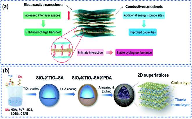 | ||
| Fig. 7 Microstructure and fabrication of 2D superlattices: (a) schematic illustration of a 2D superlattice facilitating charge transport and storage.97 Copyright 2020, Royal Society of Chemistry. (b) Schematic illustration of the fabrication of a 2D superlattice consisting of alternative layers of titania and carbon.35 Copyright 2019, Wiley-VCH. | ||
Xia and co-workers fabricated highly ordered 2D superlattice nanosheet arrays (SNAs) consisting of titania and carbon sheets with a tunable interlayer spacing between 6.89 and 7.2 Å via a molecularly mediated thermal treatment approach (Fig. 7b).35 Driven by the thermal treatment, the titania oligomers crystallized to form 2D sheets mediated by the organic molecules, which in reverse catalyzed the organic molecules into carbon layers, forming 2D SNAs. Such 2D SNAs exhibit unique properties, including (1) intimate 2D atomic interface contact between the titania layer and the carbon layer with improved electron conductivity, (2) large interfacial area, providing abundant accessible active sites for Na ions, and (3) increased interlayer spacing, facilitating Na ion diffusion. Furthermore, the authors fabricated a smart sheet-in-shell architecture with the 2D SNAs vertically oriented and encapsulated in hollow carbon spheres decorated with TiO2 quantum dots, which effectively minimized aggregation of the 2D SNAs. As a result, the 2D SNA architecture presented a nearly zero-strain characteristic during sodiation and a pseudocapacitive-controlled mechanism, achieving an excellent ultrahigh rate capability of up to 50C and superior long-term cycling stability at an ultrahigh rate of 20C over 4000 cycles.
Xiong et al. described a generalised layer-by-layer assemble approach to fabricate 2D superlattices by using single-layer graphene and other electroactive materials (Fig. 8a), including MnO2,94 Ti0.87O2,98 and MoS2,95 in which the graphene layer not only facilitated electron conduction but also suppressed the volume change of the electroactive materials. For example, MnO2/graphene consisted of alternately stacked unilamellar MnO2 nanosheets with graphene monolayers (Fig. 8b and c),99 in which the unilamellar MnO2 nanosheets (0.8 nm in thickness) were spatially separated and stabilized between two graphene sheets with a 2.2 nm distance between the adjacent MnO2 nanosheets. The unilamellar MnO2 nanosheets provided more accessible surface-active sites and shortened Na ion diffusion pathways. Besides, the intimate hybridization between the MnO2 and graphene nanosheets promoted electron transport throughout the whole superlattice, leading to improved charge transport kinetics. As a result, an excellent rate capability was achieved for both Li and Na storage with capacities of 370 mA h g−1 for Li+ and 245 mA h g−1 for Na+ measured at 12.8 A g−1. Both Ti0.87O2/graphene and MoS2/graphene superlattices prepared by using this strategy exhibited ultrafast discharge/charge capability.98 Ti-deficient Ti0.87O2 nanosheets were alternately stacked with nitrogen-doped graphene nanosheets to form a Ti0.87O2/graphene superlattice (Fig. 8d and e), which exhibited ultrahigh rate capability with a specific capacity of ∼65 mA h g−1 at 51.2 A g−1. The authors also observed a sodium-ion storage capacity of ∼100 mA h g−1 at 12.8 A g−1 measured at −5 °C.98 DFT calculations revealed that the superlattice can remarkably lower the Na ion diffusion energy barrier from 2.1 eV for Ti0.87O2 to 1.4 eV for the Ti0.87O2/graphene superlattice. The alternative restacking of 1T-MoS2 single sheets and reduced graphene oxide nanosheets yielded a MoS2/graphene superlattice (Fig. 8f and g),95 which delivered specific capacities of 240 mA h g−1 at 51.2 A g−1 and 380 mA h g−1 at 10 A g−1 over 1000 cycles due to the dramatically enhanced conductivity in the MoS2 layers and the widely exposed accessible active sites at the 2D interface.
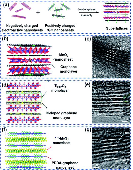 | ||
| Fig. 8 Fabrication of 2D superlattices through layer-by-layer assembly: (a) schematic illustration of the layer-by-layer strategy for fabrication of 2D superlattices, (b) structural model and (c) HRTEM image of a MnO2/graphene superlattice,94 Copyright 2018, American Chemical Society, (d) structural model and (e) HRTEM image of a Ti0.87O2/graphene superlattice,98 Copyright 2018, American Chemical Society, and (f) structural model and (g) HRTEM image of a MoS2/graphene superlattice,95 Copyright 2018, American Chemical Society. | ||
In summary, 2D superlattices combining the advantages of different 2D components exhibit improved electron conductivity and suppressed volume change of the electroactive component, leading to enhanced rate capability and cycling stability. Presently, the selection of the electroactive components is mainly limited to van der Waals layered materials (like MoS2), which can be exfoliated from their bulk precursors via chemical/physical methods. Superlattices based on non-layered structured materials have been rarely reported. Besides, the layer-by-layer assemble approach to fabricating 2D superlattices is complicated sometimes involving harsh conditions. Rational and scalable approaches deserve investigations for controllable synthesis of high-performance 2D superlattices for Na ion storage.
5. Surface-structural disorder
Structural disorder by breaking the intrinsic atom periodicity arrangement in a crystalline material in a non-repeating variation state as schematically shown in Fig. 9a can dramatically change the charge transport properties inside the material. Structural disorder occurring in the surface region of particles will destroy the periodicity of the lattice spacing while maintaining the bulk integrity, leading to increased accessible active sites for Na ion storage and lowered Na ion migration energy barrier. Usually, the surface structural disorder triggers a pseudocapacitive Na ion storage behavior, which is favorable to realize high electrochemical reaction activity and high-rate capability.34,60,61,100–104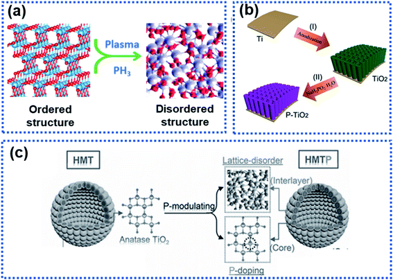 | ||
| Fig. 9 Illustration of surface-structural disorder: (a) schematic illustration of the transition of an ordered crystalline material to become disordered, (b) a scheme showing the synthesis of TiO2 tubes functionalised with a phosphorylated surface layer,102 copyright 2018, Wiley-VCH, and (c) schematic illustration of the P-modulation strategy for synthesizing surface-disordered TiO2.34 Copyright 2019, Wiley-VCH Na2Ti3O7. | ||
Wang et al. modified WS2 nanoparticles via hydrogen plasma treatment at 300 °C for 2 h. A disordered layer with a thickness of about 2.5 nm was observed at the surface of the treated WS2 nanoparticles. This layer was found to significantly lower the charge transport resistance, leading to an enhanced rate capability.105 Surface phosphorylation on TiO2 nanotube arrays could boost the Na ion storage (Fig. 9b).102 The TiO2 nanotube arrays were annealed in a PH3 gas environment to yield a disordered phosphorylated TiO2 layer in the surface region of the nanotubes (P–TiO2), resulting in surface-structural disorder due to the mismatch between the phosphate and the oxygen groups. Kinetic analysis showed that the P–TiO2 electrode stored Na ions via a pseudocapacitive mechanism, which enables the observed high redox reaction reactivity. As a result, the P–TiO2 electrode showed a significantly enhanced surface reactivity compared to pure TiO2 tubes, delivering an initial discharge capacity of 569 mA h g−1, much higher than that of the pure TiO2 tubes (402 mA h g−1). In addition, the P–TiO2 anode exhibited an enhanced rate capability with a reversible capacity of 147 mA h g−1 at 10C (only 85 mA g−1 was achieved by the pure TiO2) and long-term operating stability with 94% capacity retention after 1000 cycles at 10C.
Although enhanced electrochemical performance owing to surface-structural disorder was observed, rate capability was not obviously improved because of intrinsic sluggish charge transport properties in the bulk electrode material. Xia et al. developed a phosphorus modulation strategy to modify the TiO2 nanocrystals to boost the Na ion storage kinetics of TiO2 nanocrystals (Fig. 9c).34 The phosphorization triggered the surface structure disordering while realizing P-doping in the bulk. The electrochemical results showed that the surface-structural disorder enabled a capacitive-controlled Na ion storage behavior with boosted electrochemical activity and reaction kinetics of TiO2 nanocrystals, achieving an impressive reversible Na ion storage capacity of 210 mA h g−1 at 50C. The studies by Ni et al.102 and Xia et al.34 involved PH3, which is highly toxic and flammable. Plasma treatment and hydrogenation are promising approaches to construct a disorder surface layer.60,89,106
In summary, surface-structural disorder brings in the surface-controlled pseudocapacitive dominated Na ion storage mechanism, which is favorable for realizing high electrochemical reaction activity and efficient charge transport. Compared with other strategies, the triggered pseudocapacitive-dominated Na ion storage mechanism can significantly improve rate capability. However, this strategy usually does not change the bulk properties (like sluggish Na ion diffusion kinetics, structural instability, lattice expansion upon intercalation of Na ions, etc.) of the active materials. The synergistic strategy by combining the surface-structural disorder with the bulk heteroatom doping will be a good way to fully improve the Na ion storage properties of anode materials.
6. Surface functionalisation
Surface functionalisation by introducing electrochemical active sites accessible to Na ions is an effective way to activate the surface electrochemical reactivity. The electrochemical active sites on the surface of anode materials can achieve a rapid electrochemical interaction between the Na ions and the electrode materials, realizing dramatically enhanced surface charge storage properties.48,107–109 Surface functionalisation strategies, such as introducing functional groups, creating defects, and heteroatom doping are widely used. The active site-dominated electrochemical processes occur in forms of electrocapacitive adsorption and surface redox reactions, which do not involve solid-state ion diffusion in the bulk, thus enabling a fast Na ion storage rate.Luo and co-workers reported functionalisation of graphene sheets with C![[double bond, length as m-dash]](https://www.rsc.org/images/entities/char_e001.gif) O groups, which are active sites for electrochemical redox reactions with Na ions (Fig. 10a).110 The C
O groups, which are active sites for electrochemical redox reactions with Na ions (Fig. 10a).110 The C![[double bond, length as m-dash]](https://www.rsc.org/images/entities/char_e001.gif) O-functionalized graphene enabled fast surface adsorption/desorption of Na ions, resulting in significantly improved reaction kinetics compared with graphene without functionalisation. The electrochemical results showed that the C
O-functionalized graphene enabled fast surface adsorption/desorption of Na ions, resulting in significantly improved reaction kinetics compared with graphene without functionalisation. The electrochemical results showed that the C![[double bond, length as m-dash]](https://www.rsc.org/images/entities/char_e001.gif) O-functionalized graphene nanosheets achieved excellent rate capability with a capacity of 214 mA h g−1 delivered at 10 A g−1 and stable cycling up to 10
O-functionalized graphene nanosheets achieved excellent rate capability with a capacity of 214 mA h g−1 delivered at 10 A g−1 and stable cycling up to 10![[thin space (1/6-em)]](https://www.rsc.org/images/entities/char_2009.gif) 000 cycles at 5 A g−1 with nearly 100% capacity retention. Sun et al. reported that the carboxyl groups on coal derived carbon acted as active sites for surface Na ion capacitive adsorption via electrostatic interactions to enhance the Na ion storage performance, including reversible capacity, rate capability, and cycling stability.111 Commercial carbon black was functionalized by using the thermal treatment method in the presence of CO2 at 1050 °C (Fig. 10b).112 The surface of the functionalized carbon black was enriched with carboxyl, carbonyl, and hydroxyl groups, enabling a remarkable pseudocapacitive behavior. In addition, the surface functional groups can significantly facilitate charge transport of Na ions and solvated species, ensuing the rapid capacitive reactions on the defective surface storage, resulting in a reversible capacity of 505 mA h g−1 at 50 mA h−1. When the current density was increased to 16 A g−1, the material still delivered a capacity as high as 181 mA h g−1 in ether-based electrolytes. Besides, heteroatom doping can also increase surface active sites. Wang et al. reported the creation of multiple active-sites in amorphous meso-porous carbon spheres (MAC) via N and P element doping (Fig. 10c).48 It was found that the heteroatom doping creates numerous active sites at the surface of the MAC, facilitating fast and reversible capacitive adsorption of Na ions.
000 cycles at 5 A g−1 with nearly 100% capacity retention. Sun et al. reported that the carboxyl groups on coal derived carbon acted as active sites for surface Na ion capacitive adsorption via electrostatic interactions to enhance the Na ion storage performance, including reversible capacity, rate capability, and cycling stability.111 Commercial carbon black was functionalized by using the thermal treatment method in the presence of CO2 at 1050 °C (Fig. 10b).112 The surface of the functionalized carbon black was enriched with carboxyl, carbonyl, and hydroxyl groups, enabling a remarkable pseudocapacitive behavior. In addition, the surface functional groups can significantly facilitate charge transport of Na ions and solvated species, ensuing the rapid capacitive reactions on the defective surface storage, resulting in a reversible capacity of 505 mA h g−1 at 50 mA h−1. When the current density was increased to 16 A g−1, the material still delivered a capacity as high as 181 mA h g−1 in ether-based electrolytes. Besides, heteroatom doping can also increase surface active sites. Wang et al. reported the creation of multiple active-sites in amorphous meso-porous carbon spheres (MAC) via N and P element doping (Fig. 10c).48 It was found that the heteroatom doping creates numerous active sites at the surface of the MAC, facilitating fast and reversible capacitive adsorption of Na ions.
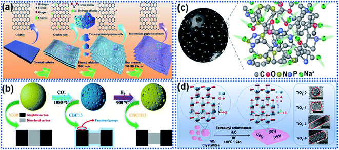 | ||
| Fig. 10 Schemes illustrating surface functionalisation strategies: (a) schematic illustration of oxygen-functionalized graphene nanosheets,110 copyright 2018, Wiley-VCH. (b) Illustration of a CO2 thermal etching route to create surface oxygenated functionalities on a commercial carbon material.112 Copyright 2020, American Chemical Society. (c) Schematic illustration of multiple active sites on amorphous mesoporous carbon spheres for interacting with Na ions.48 Copyright 2019, Wiley-VCH. (d) Schematic illustration of a fluorine modulation strategy for regulating the exposed crystal facet in TiO2 nanocrystals.113 Copyright 2020, Wiley-VCH. | ||
Apart from introducing functional groups to create surface active sites, surface structure modulation can also enhance the Na ion reaction kinetics with electrode materials. Ni et al. proposed a fluorine modulation strategy to functionalize anatase TiO2 nanocrystals.113 It was found that the fluorinated TiO2 (TiO2−xFx) nanocrystals exhibited a high ratio in the (001) facets, which are electrochemically reactive towards Na ions (Fig. 10d). The optimized TiO2−xFx nanocrystals exhibited a remarkable pseudocapacitive Na ion storage behavior with ultrahigh rate capability. Liu et al. reported the surface engineering of Na2Ti3O7 nanotube arrays via NH3-assisted calcination.114 The NH3-assisted treatment triggered the formation of a highly crystalline surface with self Ti3+ doping to achieve favorable Na ion diffusion kinetics and much improved electronic conductivity. The surface activated Na2Ti3O7 nanobelts showed improved rate capability with a capacity of 88.5 mA h g−1 at 100C and cycling stability with 92.3% capacity retention over 5000 cycles at 50C.
To sum up, surface functionalisation renders anode materials to store Na ions via a surface pseudocapacitive redox reaction mechanism, thus enabling significantly improved charge transport kinetics. Compared with other strategies, the surface functionalisation involves facile synthetic methods but show greater success in achieving high-rate capability, partially in carbon-based anode materials. Such a conception can be expanded to hard carbon anodes. Hard carbon anodes show a slop voltage–capacity profile (above 0.1 V) based on the surface Na ion adsorption process. By introduction of carbonyl groups on the surface of hard carbons, more active sites can be created, thus achieving slope-dominated hard carbon with fast discharge/charge capability.
7. Interfacial chemical bonds
High-capacity anode materials such as P, Sn, and alloys suffer from large volume expansion during cycling, leading to the rapid capacity decay. Such materials are often stabilized by using another material to form a composite via either physical bonds or chemical bonds or both. The formation of chemical bonds between an electrochemically active material and a support can significantly enhance structural stability of the active component against cycling.115 The chemical bonds also play an important role in suppressing volume expansion of the electrochemically active material upon sodiation/desodiation. Generally, two types of composite materials have chemical bonds, namely the M–C/S and M–X–C types, where M represents P, Sn, Sb, etc., C stands for carbon, S stands for sulfur, and X represents N, O, etc.For the M–C/S type composite anode materials, covalent bonds are formed between the M and C or S atoms. Li et al. employed graphite nanoplates to stabilize red P particles and observed that chemical bonds were formed between P and C. The stability of red P was significantly improved with 92.5% capacity retention after 200 cycles at 1 A g−1.116 Hu et al. reported the hybridization of red P with sulfurized polyacrylonitrile (SPAN) to prepare a composite material with P chemically bonded to SPAN forming composite P–SPAN via a mechanical ball-milling process (Fig. 11a).117 During ball milling, P–S bonds were formed between the P particles and the conductive SPAN matrix to yield P–SPAN, which was shown to be very stable against cycling. The P–SPAN hybrid delivered a specific capacity of 1300 mA h g−1 with a capacity retention of 91% after 100 cycles at 520 mA g−1. Sn–C bonds were formed between SnSe and nitrogen-doped carbon (NC) in a composite material (SnSe/NC) synthesized via a cation-exchange approach.118 The chemical Sn–C bonds facilitated electron and ion transport and stabilised the SnSe/NC heterostructure (Fig. 11b), which achieved a good charge storage reversibility with 82% capacity retention after 200 cycles at 2 A g−1.
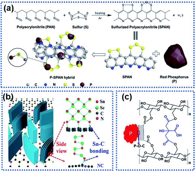 | ||
| Fig. 11 Strategies for constructing the interfacial chemical bond: (a) synthesis of a P–SPAN hybrid material with P–S bonds formed between P and SPAN.117 Copyright 2018, Wiley-VCH. (b) Schematic illustration of composite SnSe/graphene and the Sn–C bonds formed between SnSe and graphene.118 Copyright 2018, Elsevier. (c) P–O–C bond interactions between red P and sodium carboxymethyl cellulose–citric acid linked carbon nanotubes.119 Copyright 2015, American Chemical Society. | ||
For the M–X–C type composite materials, the X heteroatom plays an important part in linking the electrochemically active material and the support via chemical bonding.115 For instance, Song et al. chemically bonded P with multiwalled carbon nanotubes functionalized with carboxylic acid groups through the oxygen atoms (P–CNT, Fig. 11c).119 The red P particles were chemically bonded to the carbon nanotubes via P–O–C bonds, significantly suppressing volume expansion of red P upon sodiation. The P–CNT composite was further bonded with the cross-linked sodium carboxylmethyl cellulose–citric acid binder. The hybrid achieved a specific capacity of 1586.2 mA h g−1 over 100 cycles. A similar strategy has been used by Xu et al. to synthesize a Sb–carbon hybrid material.120
In summary, stabilizing electrochemically active materials on a support via chemical bonds can significantly enhance structural integrity, suppress volume expansion, and facilitate electron conductivity between the electroactive material and the support. However, the working mechanism of the interfacial chemical bonds and their coupling interactions lack in-depth understanding. Advanced in situ/operando characterization techniques in combination with computational simulations/calculations could be the best approach to revealing the role of the chemical bond between an electrochemical material and a support in suppressing volume expansion and promoting charge transport across the interface.
8. Comparison of the surface modification strategies
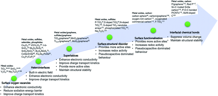
We have discussed surface engineering strategies for improving the electrochemical properties of a range of anode materials for NIBs as summarised in Table 1 and Fig. 12. Surface oxygen vacancies can significantly enhance rate capability. However, the strategy of creating surface oxygen vacancies is applicable to metal oxides with specially designed morphologies only, such as nanotubes,62 nanoarrays,68 and nanocrystals.63,65 Heterointerfaces and 2D superlattices are promising surface engineering strategies for improving charge transport kinetics by lowering the Na ion diffusion energy barrier. One of the key features of heterointerfaces is the built-in electric field, which results in charge redistribution at the interface, effectively facilitating charge transport and improving rate capability. For alloying- and conversion-type anode materials, it remains challenging to achieve long-term cycling stability due to the mechanical instability of the heterointerface caused by the large volume change upon insertion of Na ions. Strategies of 2D superlattices, surface-structural disorder and surface functionalisation increase surface active sites accessible to Na ions with a reduced sodiation energy barrier, leading to enhanced charge storage capacity. These active sites bring in an electrocapacitance-dominated redox mechanism, enabling fast Na ion storage kinetics. For example, a 2D Ti0.87O2/graphene superlattice exhibits an ultra-high rate capability and excellent long-term cycling stability over 10![[thin space (1/6-em)]](https://www.rsc.org/images/entities/char_2009.gif) 000 cycles at 10 A g−1.98 While this surface engineering strategy holds great promise, it is extremely challenging and time-consuming. Plasma treatment and hydrogenation are promising approaches to constructing a disorder surface layer. Surface functionalisation by introducing functional groups, creating defects, and heteroatom doping shows remarkable success in enhancing the rate capability of carbonaceous anode materials. Forming chemical bonds, such as P–O–C, P–S, and Sn–C between an active material and a mechanically stable support (e.g., graphene and CNTs) is important to achieve stabilization of the electrode-active material by the support.
000 cycles at 10 A g−1.98 While this surface engineering strategy holds great promise, it is extremely challenging and time-consuming. Plasma treatment and hydrogenation are promising approaches to constructing a disorder surface layer. Surface functionalisation by introducing functional groups, creating defects, and heteroatom doping shows remarkable success in enhancing the rate capability of carbonaceous anode materials. Forming chemical bonds, such as P–O–C, P–S, and Sn–C between an active material and a mechanically stable support (e.g., graphene and CNTs) is important to achieve stabilization of the electrode-active material by the support.
| Strategies | Materials | Electrochemical performance | Ref. | ||
|---|---|---|---|---|---|
| First discharge capacity (mA h g−1)/current density (mA g−1) | Cycling (mA h g−1)/cycling numbers/current density (mA g−1), capacity retention | Rate (m Ah g−1)/current density (mA g−1) | |||
| Surface oxygen vacancies (OVs) | Anatase TiO2 | 206.7/33.6 | 185.1/500/168, 99.1% | 91.2/3360 | 63 |
| TiO2 nanotube arrays | 220.8/260 | 140.4/1000/1500, 72.7% | 62 | ||
| Pinecone-like TiO2 | 510/50 | 168/5000/10![[thin space (1/6-em)]](https://www.rsc.org/images/entities/char_2009.gif) 000, 99% 000, 99% |
167/10![[thin space (1/6-em)]](https://www.rsc.org/images/entities/char_2009.gif) 000 000 |
61 | |
| SnO2−x/carbon nanofibers | 634/100 | 447/2500/2000, 106% | 340/5000 | 65 | |
| Na2Ti3O7 nanoarrays | 227/33.4 | 65/1000/6200 | 71/6200 | 68 | |
| Na2Ti3O7 particles | 420/17.7 | 145/100/344 | 80/1770 | 67 | |
| Na2Ti3O7 nanofiber arrays | 488/177 | ∼160/1000/708, ∼92.5% | 58/11![[thin space (1/6-em)]](https://www.rsc.org/images/entities/char_2009.gif) 328 328 |
77 | |
| Heterointerfaces | Sb2S3–SnS2 | 655/500 | 616/50/500, 94% | 510/10![[thin space (1/6-em)]](https://www.rsc.org/images/entities/char_2009.gif) 000 000 |
78 |
| CoSe2/ZnSe | 416/100 | ∼200/4000/10![[thin space (1/6-em)]](https://www.rsc.org/images/entities/char_2009.gif) 000, 84% 000, 84% |
263/10![[thin space (1/6-em)]](https://www.rsc.org/images/entities/char_2009.gif) 000 000 |
80 | |
| SnS/SnO2/graphene | 976/30 | 409/500/810, 73% | 430/2430 | 75 | |
| Bi2S3/MoS2 | 685/100 | 323.4/1200/10![[thin space (1/6-em)]](https://www.rsc.org/images/entities/char_2009.gif) 000 000 |
330.4/5000 | 79 | |
| Fe3Se4/FeSe@N-doped carbon nanofiber | 417.4/500 | ∼300/2000/5000, 89.1% | 269.5/10![[thin space (1/6-em)]](https://www.rsc.org/images/entities/char_2009.gif) 000 000 |
81 | |
| Cu2P7/CuP2/C | 1700 | 1254/100/200, 80% | 684/5000 | 82 | |
| Co3O4–CoO | 812.9/25 | 80.9/50/25 | 73.3/500 | 84 | |
| 2D superlattices | 2D titania-carbon superlattice arrays | ∼750/67 | 160/4000/6700 | 130/16![[thin space (1/6-em)]](https://www.rsc.org/images/entities/char_2009.gif) 750 750 |
35 |
| Unilamellar MnO2–graphene | ∼500/100 | ∼500/5000/5000, 90% | 245/12![[thin space (1/6-em)]](https://www.rsc.org/images/entities/char_2009.gif) 800 800 |
94 | |
| Unilamellar Ti0.87O2–graphene | 490/100 | 155/10![[thin space (1/6-em)]](https://www.rsc.org/images/entities/char_2009.gif) 000/10 000/10![[thin space (1/6-em)]](https://www.rsc.org/images/entities/char_2009.gif) 000 000 |
65/51![[thin space (1/6-em)]](https://www.rsc.org/images/entities/char_2009.gif) 200 200 |
98 | |
| Unilamellar MoS2–graphene | 2220/100 | 380/1000/10![[thin space (1/6-em)]](https://www.rsc.org/images/entities/char_2009.gif) 000 000 |
240/51![[thin space (1/6-em)]](https://www.rsc.org/images/entities/char_2009.gif) 200 200 |
95 | |
| Surface-structural disorder | Phosphorus modulated TiO2 nanocrystals | ∼780/67 | 190/5000/10![[thin space (1/6-em)]](https://www.rsc.org/images/entities/char_2009.gif) 050, 93% 050, 93% |
210/16![[thin space (1/6-em)]](https://www.rsc.org/images/entities/char_2009.gif) 750 750 |
34 |
| Surface-defect-rich and S doped rutile TiO2 | ∼570/50 | 128.5/6500/10![[thin space (1/6-em)]](https://www.rsc.org/images/entities/char_2009.gif) 000 000 |
101.9/10![[thin space (1/6-em)]](https://www.rsc.org/images/entities/char_2009.gif) 000 000 |
60 | |
| Nitrogen doped TiO2 with a disordered surface layer | 621/33.5 | 61.8/400/335 | 75/1675 | 100 | |
| Sulfur-doped TiO2 nanotube arrays | ∼530/33.5 | 167/4400/3350, 91% | 167/3350 | 101 | |
| Surface phosphorylated TiO2 nanotube arrays | 334/67 | 141/1000/3350, 94% | 147/3350 | 102 | |
| Na2Ti3O7 nanotube arrays | ∼530/35.4 | 78/10![[thin space (1/6-em)]](https://www.rsc.org/images/entities/char_2009.gif) 000/1770 000/1770 |
84/1770 | 103 | |
| Surface functionalisation | Multiple active site decorated carbon spheres | 200/10![[thin space (1/6-em)]](https://www.rsc.org/images/entities/char_2009.gif) 000/1000 000/1000 |
165/10![[thin space (1/6-em)]](https://www.rsc.org/images/entities/char_2009.gif) 000 000 |
48 | |
| Amorphous carbon/graphene | 230/100 | 142/2500/500, 83.5% | 120/10![[thin space (1/6-em)]](https://www.rsc.org/images/entities/char_2009.gif) 000 000 |
108 | |
| Carboxyl-dominant oxygen rich carbon | 382/30 | 141/2000/1500, 80.2% | 153/2000 | 111 | |
| Surface oxygenated commercial carbon | 505/50 | 176/1000/3200 | 181/16![[thin space (1/6-em)]](https://www.rsc.org/images/entities/char_2009.gif) 000 000 |
112 | |
| Fluorine-modulated TiO2 | 275/50 | ∼180/6000/2000, 91% | 129/10![[thin space (1/6-em)]](https://www.rsc.org/images/entities/char_2009.gif) 000 000 |
113 | |
| Interfacial chemical bond | Red phosphorus/graphene nanoplates | 1146/100 | 649/200/1000, 92.5% | 274/10![[thin space (1/6-em)]](https://www.rsc.org/images/entities/char_2009.gif) 000 000 |
116 |
| Polymer-sulfurized polyacrylonitrile/phosphorus | ∼1300/520 | 1355/100/520, 91% | 827/1300 | 117 | |
| Sn–C bonding riveted SnSe nanoplates | 723/25 | 258/200/2000, 82% | 88/20![[thin space (1/6-em)]](https://www.rsc.org/images/entities/char_2009.gif) 000 000 |
118 | |
| P–O–C bonded red P/CNTs | 2100/30 | 1586.2/100/520, 91.7% | 850/5200 | 119 | |
| Antimony/N-doped carbon | 475/100 | 439/150/100, 94.2% | 203/5000 | 120 | |
9. Summary and outlook
NIBs are considered as an alternative to LIBs for sustainable, safe and cost-effective energy storage and conversion applications. However, the current NIB technology suffers from sluggish charge transport kinetics, poor cycling stability, and low energy density. Recent advances in surface engineering of anode materials show great promise for boosting the electrochemical performance for sodium ion storage. As the forefront of an electrode material when interacting with Na ions, the surface structural properties of the electrode play a vital role in determining its electrochemical properties.Over the past decade, significant research progress has been made in improving the electrochemical properties of a wide range of NIB anode materials through surface modification. Further studies are needed for the underlying mechanism of these surface engineering strategies.
Surface oxygen vacancies in metal oxide anodes result in enhanced electronic and ionic conductivity and optimisation of the Na ion migration energy barrier, improving rate capability. Such a strategy can be realised by treating the active materials using reductants or in reducing atmosphere, which shows promise in achieving scalable production. Nevertheless, the oxygen vacancy concentration is usually uncontrollable, and the quantitative control of the oxygen vacancies allows for more precise understanding of the effects of oxygen defects on the electronic structure and the electrochemical properties of anodes. Besides, the structural stability of an oxygen-vacant surface against continuous cycling is hard to predict and lacks in-depth investigation. It is important and interesting to understand how Na ions interact with oxygen vacancies in metal oxides. In addition, the conception of partially removing anions to construct anion site defects can be extended to metal sulfides and selenides to fabricate S or Se vacancies, improving their electrochemical performance.
Heterointerfaces formed between two crystalline materials with different band gaps through lattice-matching result in a built-in electric field, which can accelerate charge redistribution and facilitate Na ion diffusion, thus improving charge transport kinetics and enhancing rate capability. Nevertheless, for alloying-type anode materials, the severe phase changes and large volume expansion during cycling can destroy the structural integrity of the heterointerface. Therefore, research efforts need to be focused on enhancing the stability of the heterointerfaces to improve Na ion storage properties of anode materials.
2D superlattices assembled from alternately stacked 2D monolayer nanosheets at atomic levels with intimate contacts at the 2D atomic interface possess enriched redox active sites for fast Na ion storage with remarkably enhanced capacity and rate capability. The utilisation of mechanically flexible building blocks, like graphene, can effectively buffer volume expansion and strengthen the structural stability of the active material to achieve long-term cycling durability. However, the existing layer-by-layer synthesis strategy results in low throughput and limited reproducibility. Facile and scalable synthetic approaches need to be developed to realize mass production of high-quality 2D superlattices and to overcome the aggregation issue. Besides, more attention should be paid to understand the Na ion storage mechanism at the 2D atomic interface, which is important in optimising the electrochemical performance.
Surface-structure disorder of anode materials can trigger pseudocapacitance-dominated redox reactions, rendering high capacity and ultrahigh rate capability. However, the widely reported synthetic methods for constructing such a disorder surface layer involve use of highly toxic and flammable PH3. Alternative approaches, like plasma treatment and hydrogenation, are more promising and safe.
The formation of chemical bonds is in favor of enhancing the structural stability of the active material against cycling, particularly for anodes of P, Sn, and alloys which suffer from large volume expansion during cycling. However, the working mechanism of the interfacial chemical bonds and their coupling interactions lack in-depth understanding. Advanced in situ/operando characterization techniques in combination with computational simulations/calculations could be the best approach to reveal the role of the chemical bond in suppressing volume expansion and understand the charge transfer dynamics across the interface.
All in all, the surface structure engineering will play an increasingly important role in electrode optimization to push the sodium-ion technology to become a reality in this beyond-lithium era.
Conflicts of interest
There are no conflicts to declare.Acknowledgements
The Australian Research Council (ARC) is acknowledged for providing funding under projects FL170100101 and DP200102573.References
- B. Dunn, H. Kamath and J. M. Tarascon, Science, 2011, 334, 928–935 CrossRef CAS PubMed.
- D. Larcher and J. M. Tarascon, Nat. Chem., 2015, 7, 19–29 CrossRef CAS PubMed.
- Z. Yang, J. Zhang, M. C. W. Kintner-Meyer, X. Lu, D. Choi, J. P. Lemmon and J. Liu, Chem. Rev., 2011, 111, 3577–3613 CrossRef CAS PubMed.
- D. M. Davies, M. G. Verde, O. Mnyshenko, Y. R. Chen, R. Rajeev, Y. S. Meng and G. Elliott, Nat. Energy, 2018, 4, 42–50 CrossRef.
- M. Palacín and A. de Guibert, Science, 2016, 351, 1253292 CrossRef PubMed.
- J.-M. Tarascon, Nat. Chem., 2010, 2, 510 CrossRef CAS PubMed.
- C. Vaalma, D. Buchholz, M. Weil and S. Passerini, Nat. Rev. Mater., 2018, 3, 18013 CrossRef.
- R. Usiskin, Y. X. Lu, J. Popovic, M. Law, P. Balaya, Y. S. Hu and J. Maier, Nat. Rev. Mater., 2021, 6, 1020–1035 CrossRef CAS.
- J.-M. Tarascon, Joule, 2020, 4, 1616–1620 CrossRef.
- N. Yabuuchi, K. Kubota, M. Dahbi and S. Komaba, Chem. Rev., 2014, 114, 11636–11682 CrossRef CAS PubMed.
- J. Y. Hwang, S. T. Myung and Y. K. Sun, Chem. Soc. Rev., 2017, 46, 3529–3614 RSC.
- T. Liu, Y. Zhang, Z. Jiang, X. Zeng, J. Ji, Z. Li, X. Gao, M. Sun, Z. Lin, M. Ling, J. Zheng and C. Liang, Energy Environ. Sci., 2019, 12, 1512–1533 RSC.
- Q. B. Xia, W. J. Li, Z. C. Miao, S. L. Chou and H. K. Liu, Nano Res., 2017, 10, 4055–4081 CrossRef CAS.
- L. Li, Y. Zheng, S. Zhang, J. Yang, Z. Shao and Z. Guo, Energy Environ. Sci., 2018, 11, 2310–2340 RSC.
- X. Xiang, K. Zhang and J. Chen, Adv. Mater., 2015, 27, 5343–5364 CrossRef CAS PubMed.
- Y. Yang, Y. Feng, Z. Chen, Y. Feng, Q. Huang, C. Ma, Q. Xia, C. Liang, L. Zhou, M. S. Islam, P. Wang, L. Zhou, L. Mai and W. Wei, Nano Energy, 2020, 76, 105061 CrossRef CAS.
- C. Zhao, Q. Wang, Z. Yao, J. Wang, B. Sánchez-Lengeling, F. Ding, X. Qi, Y. Lu, X. Bai, B. Li, H. Li, A. Aspuru-Guzik, X. Huang, C. Delmas, M. Wagemaker, L. Chen and Y.-S. Hu, Science, 2020, 370, 708 CrossRef CAS PubMed.
- C. Wang, L. Liu, S. Zhao, Y. Liu, Y. Yang, H. Yu, S. Lee, G.-H. Lee, Y.-M. Kang, R. Liu, F. Li and J. Chen, Nat. Commun., 2021, 12, 2256 CrossRef CAS PubMed.
- J. Zhang, C. Lin, Q. Xia, C. Wang and X. S. Zhao, ACS Energy Lett., 2021, 6, 2081–2089 CrossRef CAS.
- X. Shen, Q. Zhou, M. Han, X. Qi, B. Li, Q. Zhang, J. Zhao, C. Yang, H. Liu and Y.-S. Hu, Nat. Commun., 2021, 12, 2848 CrossRef CAS PubMed.
- J. Zhang, Y. Liu, X. Zhao, L. He, H. Liu, Y. Song, S. Sun, Q. Li, X. Xing and J. Chen, Adv. Mater., 2020, 32, 1906348 CrossRef CAS PubMed.
- W. Li, C. Han, W. Wang, Q. Xia, S. Chou, Q. Gu, B. Johannessen, H. Liu and S. Dou, Adv. Energy Mater., 2020, 10, 1903006 CrossRef CAS.
- W. Li, C. Han, Q. Xia, K. Zhang, S. Chou, Y.-M. Kang, J. Wang, H. K. Liu and S. X. Dou, Small Methods, 2018, 2, 1700346 CrossRef.
- W. Wang, Y. Gang, Z. Hu, Z. Yan, W. Li, Y. Li, Q.-F. Gu, Z. Wang, S.-L. Chou, H.-K. Liu and S.-X. Dou, Nat. Commun., 2020, 11, 980 CrossRef CAS PubMed.
- D. Chen, W. Zhang, K. Luo, Y. Song, Y. Zhong, Y. Liu, G. Wang, B. Zhong, Z. Wu and X. Guo, Energy Environ. Sci., 2021, 14, 2244–2262 RSC.
- A. P. Cohn, K. Share, R. Carter, L. Oakes and C. L. Pint, Nano Lett., 2016, 16, 543–548 CrossRef CAS PubMed.
- H. S. Hou, X. Q. Qiu, W. F. Wei, Y. Zhang and X. B. Ji, Adv. Energy Mater., 2017, 7, 1602898 CrossRef.
- L. Wang, J. Światowska, S. Dai, M. Cao, Z. Zhong, Y. Shen and M. Wang, Materials Today Energy, 2019, 11, 46–60 CrossRef CAS.
- J. Liu, L. Yu, C. Wu, Y. Wen, K. Yin, F. K. Chiang, R. Hu, J. Liu, L. Sun, L. Gu, J. Maier, Y. Yu and M. Zhu, Nano Lett., 2017, 17, 2034–2042 CrossRef CAS PubMed.
- J. Zhou, J. Chen, M. Chen, J. Wang, X. Liu, B. Wei, Z. Wang, J. Li, L. Gu, Q. Zhang, H. Wang and L. Guo, Adv. Mater., 2019, 31, 1807874 CrossRef PubMed.
- M. Mao, F. Yan, C. Cui, J. Ma, M. Zhang, T. Wang and C. Wang, Nano Lett., 2017, 17, 3830–3836 CrossRef CAS PubMed.
- J. Liu, Z. Yang, J. Wang, L. Gu, J. Maier and Y. Yu, Nano Energy, 2015, 16, 389–398 CrossRef CAS.
- Q. B. Xia, Y. R. Liang, Z. H. Lin, S. W. Wang, W. H. Lai, D. Yuan, Y. H. Dou, Q. F. Gu, J. Z. Wang, H. K. Liu, S. X. Dou, S. M. Fang and S. L. Chou, Adv. Energy Mater., 2020, 10, 2001033 CrossRef CAS.
- Q. Xia, Y. Huang, J. Xiao, L. Wang, Z. Lin, W. Li, H. Liu, Q. Gu, H. K. Liu and S. L. Chou, Angew. Chem. Int. Ed., 2019, 58, 4022–4026 CrossRef CAS PubMed.
- Q. Xia, Z. Lin, W. Lai, Y. Wang, C. Ma, Z. Yan, Q. Gu, W. Wei, J. Z. Wang, Z. Zhang, H. K. Liu, S. X. Dou and S. L. Chou, Angew. Chem., Int. Ed., 2019, 58, 14125–14128 CrossRef CAS PubMed.
- J. Ru, T. He, B. Chen, Y. Feng, L. Zu, Z. Wang, Q. Zhang, T. Hao, R. Meng, R. Che, C. Zhang and J. Yang, Angew. Chem., Int. Ed., 2020, 59, 14621–14627 CrossRef CAS PubMed.
- X. Xu, R. Zhao, B. Chen, L. Wu, C. Zou, W. Ai, H. Zhang, W. Huang and T. Yu, Adv. Mater., 2019, 31, e1900526 CrossRef PubMed.
- L. Wang, X. Bi and S. Yang, Adv. Mater., 2016, 28, 7672–7679 CrossRef CAS PubMed.
- D. Zhao, R. Zhao, S. Dong, X. Miao, Z. Zhang, C. Wang and L. Yin, Energy Environ. Sci., 2019, 12, 2422–2432 RSC.
- X. Wang, Y. Chen, Y. Fang, J. Zhang, S. Gao and X. W. D. Lou, Angew. Chem., Int. Ed., 2019, 58, 2675–2679 CrossRef CAS PubMed.
- Z. M. Liu, T. C. Lu, T. Song, X. Y. Yu, X. W. Lou and U. Paik, Energy Environ. Sci., 2017, 10, 1576–1580 RSC.
- M. Thompson, Q. Xia, Z. Hu and X. S. Zhao, Mater. Adv., 2021, 2, 5881–5905 RSC.
- Z. Hu, L. Wang, K. Zhang, J. Wang, F. Cheng, Z. Tao and J. Chen, Angew. Chem., Int. Ed., 2014, 53, 12794–12798 CrossRef CAS PubMed.
- J. Sun, H. W. Lee, M. Pasta, H. T. Yuan, G. Y. Zheng, Y. M. Sun, Y. Z. Li and Y. Cui, Nat. Nanotechnol., 2015, 10, 980–U184 CrossRef CAS PubMed.
- P. Xiong, P. Bai, A. Li, B. Li, M. Cheng, Y. Chen, S. Huang, Q. Jiang, X. H. Bu and Y. Xu, Adv. Mater., 2019, 31, e1904771 CrossRef PubMed.
- Y. Tian, J. Julio Gutiérrez Moreno, Z. Lu, L. Li, M. Hu, D. Liu, Z. Jian and X. Cai, Chem. Eng. J., 2021, 407, 127198 CrossRef CAS.
- L. Yang, K. Yang, J. Zheng, K. Xu, K. Amine and F. Pan, Chem. Soc. Rev., 2020, 49, 4667–4680 RSC.
- G. Wang, M. Shao, H. Ding, Y. Qi, J. Lian, S. Li, J. Qiu, H. Li and F. Huo, Angew. Chem., Int. Ed., 2019, 58, 13584–13589 CrossRef CAS PubMed.
- T. Zhou, Y. Zheng, H. Gao, S. Min, S. Li, H. K. Liu and Z. Guo, Adv. Sci., 2015, 2, 1500027 CrossRef PubMed.
- K. Share, A. Westover, M. Li and C. L. Pint, Chem. Eng. Sci., 2016, 154, 3–19 CrossRef CAS.
- W. Luo, X. Chen, Y. Xia, M. Chen, L. Wang, Q. Wang, W. Li and J. Yang, Adv. Energy Mater., 2017, 7, 1701083 CrossRef.
- L. Wang, Z. Zhou, X. Yan, F. Hou, L. Wen, W. Luo, J. Liang and S. X. Dou, Energy Storage Materials, 2018, 14, 22–48 CrossRef.
- B. Li, X. Zhang, T. Wang, Z. He, B. Lu, S. Liang and J. Zhou, Nano-Micro Letters, 2021, 14, 6 CrossRef PubMed.
- C. Xu, H. Yang, Y. Li, J. Wang and X. Lu, Chemelectrochem, 2020, 7, 586–593 CrossRef CAS.
- Y. Huang, L. Zhao, L. Li, M. Xie, F. Wu and R. Chen, Adv. Mater., 2019, 31, e1808393 CrossRef PubMed.
- H. Y. Che, S. L. Chen, Y. Y. Xie, H. Wang, K. Amine, X. Z. Liao and Z. F. Ma, Energy Environ. Sci., 2017, 10, 1075–1101 RSC.
- W. Liu, P. Liu and D. Mitlin, Adv. Energy Mater., 2020, 10, 2002297 CrossRef CAS.
- Y. Sun, P. Shi, H. Xiang, X. Liang and Y. Yu, Small, 2019, 15, 1805479 CrossRef PubMed.
- Q. Wang, S. Zhang, H. He, C. Xie, Y. Tang, C. He, M. Shao and H. Wang, Chem. - Asian J., 2021, 16, 3–19 CrossRef CAS PubMed.
- H. He, D. Huang, W. Pang, D. Sun, Q. Wang, Y. Tang, X. Ji, Z. Guo and H. Wang, Adv. Mater., 2018, 30, e1801013 CrossRef PubMed.
- Q. Gan, H. He, Y. Zhu, Z. Wang, N. Qin, S. Gu, Z. Li, W. Luo and Z. Lu, ACS Nano, 2019, 13, 9247–9258 CrossRef CAS PubMed.
- J. Chen, Y. Fu, F. Sun, Z. Hu, X. Wang, T. Zhang, F. Zhang, X. Wu, H. Chen, G. Cheng and R. Zheng, Chem. Eng. J., 2020, 400, 125784 CrossRef CAS.
- J. Chen, Z. Ding, C. Wang, H. Hou, Y. Zhang, C. Wang, G. Zou and X. Ji, ACS Appl. Mater. Interfaces, 2016, 8, 9142–9151 CrossRef CAS PubMed.
- D. Ma, Y. Li, P. Zhang and Z. Lin, ChemSusChem, 2018, 11, 3693–3703 CrossRef CAS PubMed.
- D. Ma, Y. Li, H. Mi, S. Luo, P. Zhang, Z. Lin, J. Li and H. Zhang, Angew. Chem., Int. Ed., 2018, 57, 8901–8905 CrossRef CAS PubMed.
- Q. Ren, N. Qin, B. Liu, Y. Yao, X. Zhao, Z. Deng, Y. Li, Y. Dong, D. Qian, B.-L. Su, W. Zhang and H.-E. Wang, J. Mater. Chem. A, 2020, 8, 3450–3458 RSC.
- S. I. R. Costa, Y.-S. Choi, A. J. Fielding, A. J. Naylor, J. M. Griffin, Z. Sofer, D. O. Scanlon and N. Tapia-Ruiz, Chem. - Eur. J., 2021, 27, 3875–3886 CrossRef CAS PubMed.
- S. Fu, J. Ni, Y. Xu, Q. Zhang and L. Li, Nano Lett., 2016, 16, 4544–4551 CrossRef CAS PubMed.
- C. Chen, Y. Wen, X. Hu, X. Ji, M. Yan, L. Mai, P. Hu, B. Shan and Y. Huang, Nat. Commun., 2015, 6, 6929 CrossRef CAS PubMed.
- N. N. Wang, C. X. Chu, X. Xu, Y. Du, J. Yang, Z. C. Bai and S. X. Dou, Adv. Energy Mater., 2018, 8, 1801888 CrossRef.
- S. H. Guo, J. Yi, Y. Sun and H. S. Zhou, Energy Environ. Sci., 2016, 9, 2978–3006 RSC.
- S. Lou, Y. Zhao, J. Wang, G. Yin, C. Du and X. Sun, Small, 2019, 15, 1904740 CrossRef CAS PubMed.
- Z. Li, J. Ding and D. Mitlin, Acc. Chem. Res., 2015, 48, 1657–1665 CrossRef CAS PubMed.
- Z. Su, J. Liu, M. Li, Y. Zhu, S. Qian, M. Weng, J. Zheng, Y. Zhong, F. Pan and S. Zhang, Electrochem. Energy Rev., 2020, 3, 286–343 CrossRef CAS.
- Y. Zheng, T. Zhou, C. Zhang, J. Mao, H. Liu and Z. Guo, Angew. Chem., Int. Ed., 2016, 55, 3408–3413 CrossRef CAS PubMed.
- N. Wang, X. Xu, T. Liao, Y. Du, Z. Bai and S. Dou, Adv. Mater., 2018, 30, e1804157 CrossRef PubMed.
- D. Kong, Y. Wang, S. Huang, Y. V. Lim, J. Zhang, L. Sun, B. Liu, T. Chen, P. Valdivia y Alvarado and H. Y. Yang, J. Mater. Chem. A, 2019, 7, 12751–12762 RSC.
- L. Fang, Z. Lan, W. Guan, P. Zhou, N. Bahlawane, W. Sun, Y. Lu, C. Liang, M. Yan and Y. Jiang, Energy Storage Materials, 2019, 18, 107–113 CrossRef.
- L. Cao, X. Liang, X. Ou, X. Yang, Y. Li, C. Yang, Z. Lin and M. Liu, Adv. Funct. Mater., 2020, 30, 1910732 CrossRef CAS.
- G. Fang, Q. Wang, J. Zhou, Y. Lei, Z. Chen, Z. Wang, A. Pan and S. Liang, ACS Nano, 2019, 13, 5635–5645 CrossRef CAS PubMed.
- J. Liu, S. Xiao, X. Li, Z. Li, X. Li, W. Zhang, Y. Xiang, X. Niu and J. S. Chen, Chem. Eng. J., 2021, 417, 129279 CrossRef CAS.
- X. W. Li, J. Liao, P. F. Shen, X. Lia, Y. Y. Li, N. Li, Z. H. Li, Z. C. Shi, H. Y. Zhang and W. W. Li, J. Alloys Compd., 2019, 803, 804–811 CrossRef CAS.
- Y.-Y. Wang, B.-H. Hou, Y.-N. Wang, H.-Y. Lü, J.-Z. Guo, Q.-L. Ning, J.-P. Zhang, C.-L. Lü and X.-L. Wu, J. Mater. Chem. A, 2018, 6, 6578–6586 RSC.
- Y. Liu, H. Wan, H. Zhang, J. Chen, F. Fang, N. Jiang, W. Zhang, F. Zhou, H. Arandiyan, Y. Wang, G. Liu, Z. Wang, S. Luo, X. Chen and H. Sun, ACS Appl. Nano Mater., 2020, 3, 3892–3903 CrossRef CAS.
- Y. Li, J. Zhang, Q. Chen, X. Xia and M. Chen, Adv. Mater., 2021, 33, 2100855 CrossRef CAS PubMed.
- S. Chen, S. Huang, J. Hu, S. Fan, Y. Shang, M. E. Pam, X. Li, Y. Wang, T. Xu, Y. Shi and H. Y. Yang, Nano-Micro Letters, 2019, 11, 80 CrossRef CAS PubMed.
- G. Liu, H.-H. Wu, Q. Meng, T. Zhang, D. Sun, X. Jin, D. Guo, N. Wu, X. Liu and J.-K. Kim, Nanoscale Horiz., 2020, 5, 150–162 RSC.
- B. Zhao, Q. Q. Liu, Y. J. Chen, Q. Liu, Q. Yu and H. B. Wu, Adv. Funct. Mater., 2020, 30, 2002019 CrossRef CAS.
- T. Xia, W. Zhang, J. Murowchick, G. Liu and X. Chen, Nano Lett., 2013, 13, 5289–5296 CrossRef CAS PubMed.
- W. Luo, F. Li, Q. Li, X. Wang, W. Yang, L. Zhou and L. Mai, ACS Appl. Mater. Interfaces, 2018, 10, 7201–7207 CrossRef CAS PubMed.
- J. Ni, M. Sun and L. Li, Adv. Mater., 2019, 31, 1902603 CrossRef CAS PubMed.
- W. Li, Q. Song, M. Li, Y. Yuan, J. Zhang, N. Wang, Z. Yang, J. Huang, J. Lu and X. Li, Small Methods, 2021, 5, 2100444 CrossRef CAS PubMed.
- P. Xiong, B. Sun, N. Sakai, R. Ma, T. Sasaki, S. Wang, J. Zhang and G. Wang, Adv. Mater., 2019, e1902654 Search PubMed.
- P. Xiong, R. Ma, N. Sakai and T. Sasaki, ACS Nano, 2018, 12, 1768–1777 CrossRef CAS PubMed.
- P. Xiong, R. Ma, N. Sakai, L. Nurdiwijayanto and T. Sasaki, ACS Energy Lett., 2018, 3, 997–1005 CrossRef CAS.
- E. Pomerantseva and Y. Gogotsi, Nat. Energy, 2017, 2, 17089 CrossRef CAS.
- P. Xiong, Y. Wu, Y. Liu, R. Ma, T. Sasaki, X. Wang and J. Zhu, Energy Environ. Sci., 2020, 13, 4834–4853 RSC.
- P. Xiong, X. Zhang, F. Zhang, D. Yi, J. Zhang, B. Sun, H. Tian, D. Shanmukaraj, T. Rojo, M. Armand, R. Ma, T. Sasaki and G. Wang, ACS Nano, 2018, 12, 12337–12346 CrossRef CAS PubMed.
- Y. Jiang, M. Sun, J. Ni and L. Li, ACS Appl. Mater. Interfaces, 2019, 11, 37761–37767 CrossRef CAS PubMed.
- H. Wang, J. Xiong, X. Cheng, G. Chen, T. Kups, D. Wang and P. Schaaf, Sustainable Energy Fuels, 2019, 3, 2688–2696 RSC.
- J. Ni, S. Fu, C. Wu, J. Maier, Y. Yu and L. Li, Adv. Mater., 2016, 28, 2259–2265 CrossRef CAS PubMed.
- J. Ni, S. Fu, Y. Yuan, L. Ma, Y. Jiang, L. Li and J. Lu, Adv. Mater., 2018, 30, 1704337 CrossRef PubMed.
- J. F. Ni, S. D. Fu, C. Wu, Y. Zhao, J. Maier, Y. Yu and L. Li, Adv. Energy Mater., 2016, 6, 1502568 CrossRef.
- S. Yan, K. P. Abhilash, L. Tang, M. Yang, Y. Ma, Q. Xia, Q. Guo and H. Xia, Small, 2019, 15, 1804371 Search PubMed.
- H. Wang, Q. Yuan, D. Wang, G. Chen, X. Cheng, T. Kups and P. Schaaf, Sustainable Energy Fuels, 2019, 3, 865–874 RSC.
- T. Xia, W. Zhang, W. Li, N. A. Oyler, G. Liu and X. Chen, Nano Energy, 2013, 2, 826–835 CrossRef CAS.
- Y. Zhang, Y. Huang, V. Srot, P. A. van Aken, J. Maier and Y. Yu, Nano-Micro Letters, 2020, 12, 165 CrossRef PubMed.
- S. Li, J. Qiu, C. Lai, M. Ling, H. Zhao and S. Zhang, Nano Energy, 2015, 12, 224–230 CrossRef CAS.
- B. Babu, P. Simon and A. Balducci, Adv. Energy Mater., 2020, 10, 2001128 CrossRef CAS.
- D. Luo, J. Xu, Q. Guo, L. Fang, X. Zhu, Q. Xia and H. Xia, Adv. Funct. Mater., 2018, 28, 1805371 CrossRef.
- F. Sun, H. Wang, Z. Qu, K. Wang, L. Wang, J. Gao, J. Gao, S. Liu and Y. Lu, Adv. Energy Mater., 2021, 11, 2002981 CrossRef CAS.
- W. Xiao, Q. Sun, J. Liu, B. Xiao, X. Li, P.-A. Glans, J. Li, R. Li, X. Li, J. Guo, W. Yang, T.-K. Sham and X. Sun, ACS Appl. Mater. Interfaces, 2020, 12, 37116–37127 CrossRef CAS PubMed.
- M. Ni, D. Sun, X. Zhu, Q. Xia, Y. Zhao, L. Xue, J. Wu, C. Qiu, Q. Guo, Z. Shi, X. Liu, G. Wang and H. Xia, Small, 2020, 16, 2006366 CrossRef CAS PubMed.
- J. Liu, Z. Wang, Z. Lu, L. Zhang, F. Xie, A. Vasileff and S.-Z. Qiao, ACS Mater. Lett., 2019, 1, 389–398 CrossRef CAS.
- S. Li, L. Zhang, W. Zhao, S. Yuan, L. Yang, X. Chen, P. Ge, W. Sun and X. Ji, Energy Storage Materials, 2020, 32, 477–496 CrossRef.
- W.-J. Li, S.-L. Chou, J.-Z. Wang, H.-K. Liu and S.-X. Dou, J. Mater. Chem. A, 2016, 4, 505–511 RSC.
- Y. Hu, B. Li, X. Jiao, C. Zhang, X. Dai and J. Song, Adv. Funct. Mater., 2018, 28, 1801010 CrossRef.
- X. Ren, J. Wang, D. Zhu, Q. Li, W. Tian, L. Wang, J. Zhang, L. Miao, P. K. Chu and K. Huo, Nano Energy, 2018, 54, 322–330 CrossRef CAS.
- J. Song, Z. Yu, M. L. Gordin, X. Li, H. Peng and D. Wang, ACS Nano, 2015, 9, 11933–11941 CrossRef CAS PubMed.
- X. Xu, L. Si, X. Zhou, F. Tu, X. Zhu and J. Bao, J. Power Sources, 2017, 349, 37–44 CrossRef CAS.
| This journal is © The Royal Society of Chemistry 2022 |

