
 Open Access Article
 This Open Access Article is licensed under a
 Creative Commons Attribution 3.0 Unported Licence
Development of trash exclusion for mechanized pit latrine emptying†
Giovanna F.
Portiolli
 a,
Tate W.
Rogers
b,
Walter
Beckwith
a,
Jocelyn
Tsai
a,
Payan
ole-MoiYoi
cd,
Noel
Wilson
d and
Francis L.
de los Reyes
III
*a
a,
Tate W.
Rogers
b,
Walter
Beckwith
a,
Jocelyn
Tsai
a,
Payan
ole-MoiYoi
cd,
Noel
Wilson
d and
Francis L.
de los Reyes
III
*a
aDepartment of Civil, Construction, and Environmental Engineering, North Carolina State University, 915 Partners Way, 3250 Fitts Woolard Hall, Raleigh, NC 27606, USA. E-mail: fldelosr@ncsu.edu
bTriangle Environmental Health Initiative, LLC, 105 Hood St Ste 3., Durham, NC 27701, USA
cImplement – Product Design, P.O. Box 119-00502, Kilifi, Kenya
dCatapult Design, 4910 Brighton Blvd # 16023, Denver, CO 80216, USA
First published on 12th August 2021
Abstract
Nearly 1.8 billion people use pit latrines for basic sanitation, and approximately 600 million kg of feces and 2.1 billion kg of urine are deposited in pit latrines every day. Due to lack of access to mechanized emptying services, or challenges such as the presence of trash in pits, most latrines are emptied by hand. Alternatively, “fishing” (removal of trash using manual tools) is used prior to mechanical emptying. Both approaches are time consuming and expose workers to pathogens. To develop a safer method of emptying pit latrines, we explored mechanized trash exclusion, allowing the removal of fecal sludge in the presence of trash. Three exclusion mechanisms: screening, deflecting, and clearing, were investigated. The effects of varying design features, such as the diameter of screen holes, length of screen pipe, auger characteristics, level of negative pressure (vacuum setting), and rotational speeds, were evaluated in pits with varying solids concentrations. Continuous prototyping and testing showed that a combination of the screening and clearing mechanisms was most efficient in excluding trash in wet pits (less than 12% solids) and allowed a maximum flow rate of between 3 to 4.5 L s−1. The resulting product, called the Flexcrevator + Excluder, is a vacuum system that excludes trash and was field-tested in pit latrines in Kisumu, Kenya. While there are remaining challenges for the current design such as pumping thick fecal sludge and dealing with fibrous material encountered in the field, trash exclusion can provide an efficient and safe emptying solution for a wide range of pit latrines.
Water impactOne of the biggest challenges in fecal sludge management is developing a mechanized pit emptying technology that can empty trash-filled pits. The attachment head design developed (Excluder) allows the removal of fecal sludge even in the presence of trash in pits. The concept of trash exclusion makes emptying faster and more hygienic than manual methods. |
1. Introduction
Pit latrines are the most basic and affordable form of improved sanitation. As populations grow and countries commit to following the United Nations' Sustainable Development Goal 6 of ending open defecation by 2030, the number of improved onsite facilities (pit latrines and septic tanks) is expected to increase from an estimated 590 million, with an estimated 1.77 billion people using pit latrines.1 These pits need periodic emptying to remain useable and to prevent overflows.The most common method of emptying pit latrines is manual emptying, where people remove fecal sludge using tools such as buckets and shovels.2,3 This emptying method is unsafe for the workers,2,4 especially when protective equipment is not used. Often, the emptier has to enter the pit, further increasing the risks.5 In addition to health hazards, workers suffer social stigmatization. Manual emptying is considered illegal in several countries, and emptiers often work at night and are subject to violence.6,7 Many work under the influence of alcohol to withstand the odor, which leads to unsafe work, more spillages, and improper procedures.8
To aid or eliminate manual emptying, mechanized systems have been developed. These can be divided into human-powered or engine-powered systems.2 Examples of human powered mechanized technologies are the manual pit latrine emptying technology (MAPET)9 and the Gulper,8 the latter being the most used human-powered mechanized pit emptying method in both Africa and Asia.10 Amongst the engine-powered systems, vacuum trucks are most common. These trucks typically empty septic tanks that support a large number of people, such as at businesses, hotels, schools, and hospitals. However, for residential pit latrines, contracting a vacuum truck is rarely an available or affordable option. Lack of financial resources, overcrowding, and physically narrow spaces that restrict access are primary factors that limit the use of vacuum trucks.11 Other technologies have been developed as vacuum truck alternatives, such as the Vacutug, which uses a vacuum pump and a 500 L steel tank,8 the Evac, which uses a vane pump along with 40 L interchangeable lid containers,12 and the Excrevator,13 which uses a continuous auger. While these systems can access latrines better than vacuum trucks, a major difficulty these technologies encounter is trash in the pits.
Lack of adequate solid waste management systems in areas where people rely on pit latrines means that many dispose garbage directly into the pits.14 Sludge characteristics in pit latrines vary greatly, even in the same city, area, or even adjacent households.15 User practices contribute greatly to this variability, such as differences in diets and anal cleansing material.16 Garbage found inside latrines around the world include stones, sanitary pads, condoms, bricks,3 plastic bags, broken glass, cloth,17 newspapers, and anal cleansing material.18 In Malawi, a mean volume of 60 L trash per latrine has been reported.3 Clearing trash-clogged vacuum systems by hand leads to fecal sludge exposure and longer operating time compared to no clearing (e.g., up to 1.5 hours with the Vacutug).12 A common method to handle trash is the practice of “fishing”: an emptier often “fluidizes”, or adds water, while mixing the pit contents, solid waste gets dislodged or floats to the top of the pit, and emptiers “fish” out trash with special tools prior to removing the fecal sludge.19 However, “fishing” takes time and adds health risks to emptiers due to close contact with fecal-covered trash.
There is a tremendous need for safe and efficient pit emptying solutions that would allow the pit emptying industry to gain legitimacy, enable more dignified work for the emptiers, and promote better sanitation practices in communities. Such solutions would allow sludge to be moved out of pits safely, bringing to the forefront the need for improved downstream treatment technologies. This technology should ideally be portable, affordable, hygienic, and efficient.
Previously, we developed a method that used a vacuum system and a continuous auger conveyed sludge through a rigid pipe.13 However, the presence of trash in pits greatly inhibited pit emptying, and various ideas such as in-pit trash maceration were explored.19 However, reducing the size of trash particles to avoid clogging of pipes was energetically prohibitive.
In the current study, we developed a new method called active trash exclusion, where fecal sludge is pumped out of the pit while trash is left behind inside the latrine or septic tank. The design, lab testing, and field testing results of this new concept of trash exclusion are described.
2. Materials and methods
The goal of the study was to test different attachments to the vacuum system that would exclude trash during pumping of fecal sludge from a below-ground pit to above ground. The attachments had different configurations and were powered by either a solid or flexible shaft that was connected to a 1.2 kVA electric motor with a rheostat to control rotational speed. Fecal sludge was extracted using a vacuum pump into a collection tank, which in the field could be a portable barrel-based system or a vacuum tanker truck.2.1. Testing setup
The custom vacuum setup (Fig. 1) consisted of a Condé ProVac 3 Vacuum Pump (Westmoor, Ltd; A in Fig. 1) powered by a 1.75 kVA motor, which was connected to a 90 L vacuum tank (C) via a vacuum hose (B). The tank was connected (F) to a trash excluding attachment (G and H) through a 2 m long hose (E). During operation, sludge was pumped through the attachment and into the vacuum tank, and pressure gauges at the vacuum pump and on the vacuum tank (K) allowed an operator to monitor sludge flow. Under laboratory conditions, a full vacuum tank was emptied into a modeled pit latrine via a sludge return line (D) in preparation for the next batch test (Fig. 1).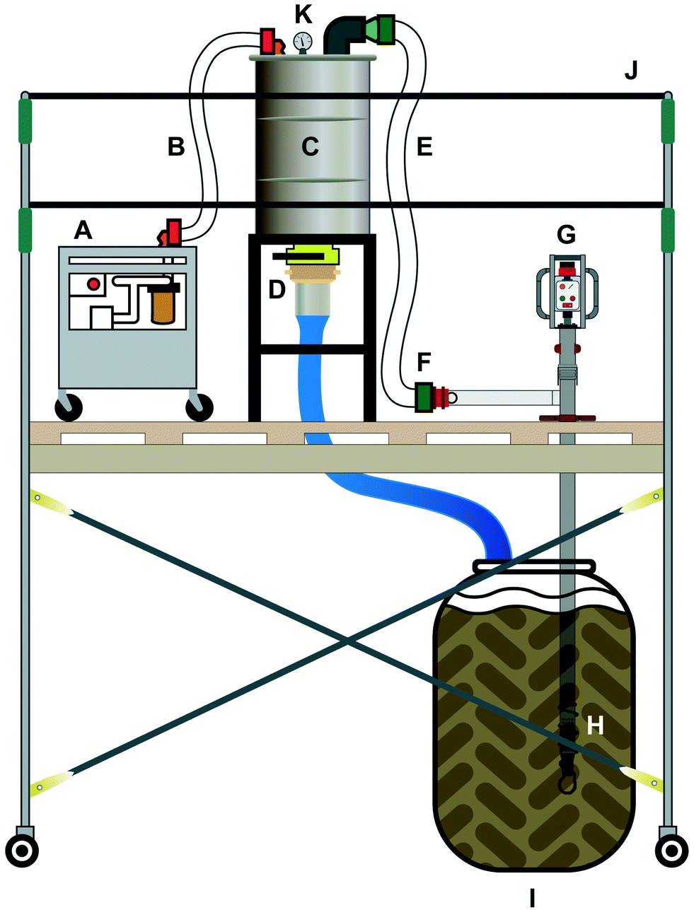 | ||
| Fig. 1 Testing setup in the laboratory. A. Vacuum pump; B. vacuum hose; C. vacuum tank; D. return line to simulated pit; E. vacuum hose from excluder attachment to tank; F. cam lock connector; G. attachment motor; H. trash exclusion head; I. simulated pit latrine; J. scaffolding; K. pressure gauge. | ||
2.2. Simulated pit latrines
Laboratory testing was conducted at NC State University (Raleigh, North Carolina, USA) and in Nairobi, Kenya. Model pit latrines used 208 L drums with bentonite clay to serve as a fecal sludge simulant. Bentonite slurry mimics important fecal sludge rheological characteristics while being biologically stable and pathogen free.13 Mixtures of water and bentonite clay at 0, 3, 7, 9, 10, and 12% solids (by weight) were prepared to simulate fecal sludge at different viscosities. Laboratory testing confirmed that these bentonite mixtures exhibited similar rheological properties as fecal sludge (ESI† 1). In this study, we used 0% bentonite to simulate septic tank wastewater, 3–7% bentonite to simulate thin sludge found in wet pit latrines, and 9–12% bentonite to simulate thick fecal sludge in wet and dry pit latrines. The model pit latrine also contained a standard trash formulation20 and contained items such as but not limited to plastic bags, condoms, magazines, and sanitary napkins (Table 1).| Debris description | Units | Number of units |
|---|---|---|
| Toilet paper (whole roll, unrolled) | Rolls | 6 |
| Paper towel (separated individual sheets) | Sheets | 21 |
| Sanitary napkins (including all packaging) | Units | 12 |
| Tampons (including all packaging) | Units | 23 |
| Condoms (including all packaging) | Units | 22 |
| Hair, synthetic, use wig or extensions, 250 mm min. Length | Clumps | 8 |
| Small biodegradable green waste bag (approx. 30 cm sq.) | Units | 32 |
| Small biodegradable green waste bag containing 50 g of simulant, knotted | Units | 11 |
| Newspaper (A2 sheet cut into pieces approx. 75 mm × 150 mm) | Sheets | 41 |
| 500 mL PET bottle, twisted axially | Units | 13 |
| 500 mL PET bottle, crushed axially | Units | 13 |
| Magazine paper, glossy (A4 sheet cut into pieces approx. 75 mm × 150 mm) | Sheets | 6 |
| Fabric, cotton t-shirt material (cut into pieces approx. 75 mm × 150 mm) | Sheets | 110 |
2.3. Testing different attachment heads
Different attachments for excluding trash using a variety of mechanisms were explored (Fig. 2, features summarized in Table 2). All pipes had a diameter of 7.62 cm, as this is similar to standard diameters used in current desludging practices (e.g., vacuum truck hoses), and fit almost all pit latrine openings. Design A uses a continuous auger that rotates to convey sludge (with and without a vacuum), and is similar to the auger design previously reported.13 Previous field work in Mzuzu, Malawi and Hyderabad, India showed that this approach resulted in trash wrapping around the auger, causing clogs and blocking sludge flow. Design B uses an auger extending beyond the end of the pipe; here the auger rotation is such that trash is pushed away from the pipe entrance, while a vacuum pulls sludge into the pipe. Design C shows a functionally equivalent head to design B, but with better quality sealing and off-the-shelf components. Both designs B and C were tested in Lusaka, Zambia; in pits with thick sludge and high amounts of trash (similar to levels in Table 1), debris was found to interfere with pumping, and these designs were eliminated from further testing.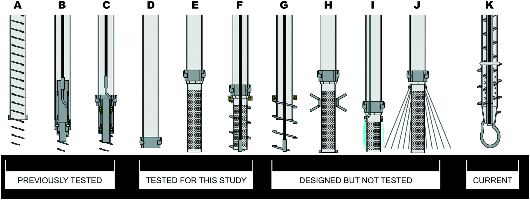 | ||
| Fig. 2 Attachment designs investigated as part of this study. Designs A–K are discussed below. Design D is the baseline (open pipe). The effect of the screen length was tested using Design E. Design F was extensively tested in the laboratory and field and is the basis for the Excluder design (Design K). | ||
| Design | Description | Mechanism for dealing with trash |
|---|---|---|
| A | Internal auger extending beyond pipe | Deflection |
| B | External auger with flexible cable | Deflection |
| C | Modified design B | Deflection |
| D | Open pipe (used as baseline) | None |
| E | Screen | Screening |
| F | Screen + external auger/flexible cable | Either screening + deflection or screening + clearing |
| G | External auger/flexible cable | Deflection |
| H | Screen + swiper mechanism | Screening + clearing |
| I | Screen + water spray | Screening + clearing |
| J | Screen + wire shield | Screening + clearing |
| K | The excluder, based on a modified design F, with a loop attachment and internal auger | Screening + clearing + internal clearing of fiber |
New designs to manage trash were then evaluated. First, the base case (an open hose, design D) was used to evaluate the flow rates of sludge with different viscosities (without trash) when aspirated through the laboratory testing setup. After establishing baseline flowrates, a variety of attachment heads were designed based on the following principles:
Design G was not tested as other design investigations showed the importance of limiting the size of trash that enter the hose. Designs H–J were not pursued after initial assessment revealed additional mechanical complexity. Thus, designs E and F (both clearing and deflecting mechanisms for design F) were tested. These tests led to design K, which is an updated and optimized design F, with the following revised features: (1) a rigid shaft and internal auger was used in design K instead of a flexible (cable) shaft, and to help clear the screen from the inside (in response to fibers clogging the screen- see Results); (3) a lower loop was added to connect the rigid internal shaft to the outer auger. This loop allowed trash that was cleared from the screen a higher potential to fall to the bottom of the pit without being entangled in the auger connection.
2.4. Screening head
Screening via a perforated pipe (design E, Fig. 2) was conceptually simple: when a vacuum is applied to a hose, trash stays on the outside of the perforated screen. The number of holes in the screen was chosen so that the total area of the holes (sum of all areas of all the screen holes) was greater than or equal to the cross-sectional area of the pipe (inside diameter = 7.62 cm, cross-sectional area = 45.6 cm2). The effect of screen length on flow rate was determined for perforated pipes 10, 20, and 25 cm in length and with 1.2 cm diameter holes. In addition to screen length, the effects of various screen-hole diameters on flow rate were determined. Our previous field observations indicated that plastic bags and human hair were the trash items that caused clogs most frequently. Pipe screen-hole diameters of 0.12, 0.48, and 0.64 cm were tested to prevent pieces of debris from entering the vacuum hose.2.5. Deflecting and clearing heads
Design F could be operated in both deflecting and clearing mode. A deflecting head had an auger welded directly to a perforated metal pipe. The rapid auger rotation (∼300 rpm or higher) provided a deflecting force that in theory prevented the trash from clinging to the perforated pipe (ESI† 3). The clearing head had an auger with a narrow gap between the auger and the screen. There are two versions of this design: either the auger is rotating around a fixed screen, or the screen is rotating inside a fixed auger. Either way, the trash is scraped, clearing the screen. Augers were constructed with schedule 304 stainless steel strips, 0.48 cm thick, with 10.64 cm OD and 8.10 cm ID (ESI† 4).The deflecting and clearing heads were tested at different rotational speeds (300 and 550 rpm) and different vacuum settings (203, 254, and 381 mm Hg). Flow rates were calculated using the time to fill a 90 L vacuum tank. Laboratory acceptance criteria for proceeding to field testing included: (1) meeting a minimum flow rate of 1.5 L s−1, (2) successfully emptying two low solids (0% and 8% bentonite) and three high solids (9%, 10%, and 11% bentonite) simulated pits with trash in a row (without being cleaned between runs), and (3) having a maximum of one clog per run.
2.6. Field testing
Prototype attachment heads based on design F (both deflecting and clearing modes, and both versions of the clearing head) that met the lab acceptance criteria were tested in five pit latrines in Kisumu, Kenya on June 25–30, 2018. The team worked with the Gasia Poa pit emptying team and used a custom vacuum unit operating at 381 mm Hg with the auger spinning at either 300 or 550 rpm. An attachment (based on design F) was also tested by connecting it to a vacuum truck, with the assistance of the Kisumu Water and Sanitation Co., Kenya. Operational data, such as the times needed for setting up, pumping sludge, managing barrels, and system cleaning, were recorded.The field testing revealed an unforeseen type of trash: vegetable fibers in human waste. Subsequent laboratory testing was modified by adding coconut coir (≈ 300 mL per 210 L of simulant sludge) to 9% bentonite mixture with trash to simulate the natural fibers found in the field.
3. Results and discussion
3.1. Baseline and effect of screen length
The baseline flow rates for bentonite through an open 7.62 ID hose (design D) were 4.76 L s−1 for 0% bentonite, 4.45 L s−1 for 3% bentonite, 4.56 L for 7% bentonite, 3.79 L s−1 for 9% bentonite, and 1.40 L s−1 for 12% bentonite. Surprisingly, the length of the screen did not have a significant effect on the flow rate of the fecal sludge simulant in the absence of trash (Fig. 3a).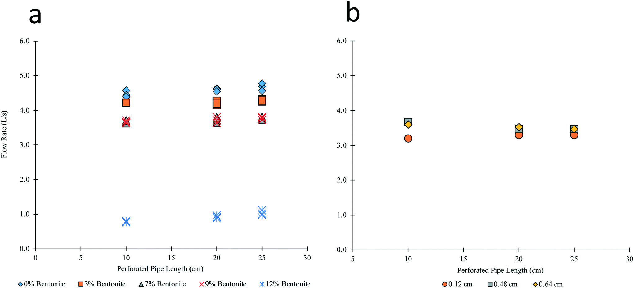 | ||
| Fig. 3 a) Effect of different lengths of perforated pipe with 1.27 cm diameter holes on flow rate (left) b) flow rate vs. length of perforated pipe in 10% bentonite with different hole sizes (right). | ||
However, the increased viscosity of the sludge at 12% bentonite decreased the flow rates from >3 L s−1 to <1.5 L s−1. This result illustrates the significant impact of pit viscosity on flow rates; a “dry” pit with viscosities equal to that of 12% bentonite slurry would have markedly lower flow rates (ESI†Fig. 1).
3.2. Effect of screen hole size
The flow rates in all screens with the tested diameters and lengths were >3.0 L s−1 when tested in 10% bentonite (Fig. 3b). This shows that the length of the screen is not a significant factor if the total perforated surface area is at least equivalent to a pipe cross sectional area. When the fecal sludge simulant included trash, the flow rate decreased markedly. Flow rates of bentonite through a 25.4 cm perforated pipe with 0.48 cm diameter holes were 0.7 L s−1 for 0% bentonite, 0.8 L s−1 for 10% bentonite, and 1.3 L s−1 for 12% bentonite, which were below the acceptable rate of 1.5 L s−1. This shows that pit latrine emptiers cannot rely on a screen alone to keep trash from entering the unit. Interestingly, the flow rate was higher with the more viscous slurry. This is likely due to a faster clogging rate in less viscous sludge, as trash pieces moved toward the screen faster.3.3. Deflecting method
When the deflecting head (design F in deflecting mode) with a screen hole size of 0.64 cm was tested in water with trash, plastic bags lodged in between the screen and auger flights (the gap between successive auger steel bars), even with additional auger flights and at 300 and 500 rpm. Lodging of plastic bags also occurred at a higher rpm (up to 1000 rpm) and a lower vacuum (down to 254 mm Hg). Interestingly, when the pipe inlet was partially submerged in the sludge, with about half the screen above the sludge level, the vacuum and deflection forces appeared to be in balance, and the unit successfully rejected trash and emptied a full 90 L barrel of water, 8% bentonite, and 10% bentonite sludge.3.4. Clearing method
Two versions of the clearing head (design F, in clearing mode) were tested: one with the perforated screen rotating inside a stationary auger, and the other with a stationary screen while the auger rotated. With the stationary auger configuration, plastic bags lodged between the screen and the auger, and the 1.5 hp motor was not able to maintain rotation. On the other hand, the rotating auger successfully excluded and cleared plastic bags and hair while emptying full simulated pits in water and 10% bentonite sludge. Subsequently, the rotating auger design was used to test the impact of vacuum and rotational speeds on sludge flow rates. Flow rates could largely be maintained above 1.5 L s−1 if the vacuum pressure was above 203 mm Hg (Table 3).| Vacuum setting | Water | Water | 9% bentonite |
|---|---|---|---|
| 300 rpm | 550 rpm | 550 rpm | |
| 203 mm Hg | 0.34 | — | — |
| 254 mm Hg | 2.67 | 1.93 | — |
| 381 mm Hg | 1.64 | 3.46 | 2.42 |
At 300 rpm, it appeared that the rotation was not fast enough to clear trash, and the screen frequently clogged at 203 mm Hg, resulting in a low flow rate. At 254 mm Hg, the flow rate increased, although trash still accumulated on the screen and eventually clogged the pipe. The higher speed of 550 rpm and higher vacuum of 381 mm Hg yielded an average flow rate of 3.46 L s−1 in water and 2.42 L s−1 in 9% bentonite, and successfully emptied a simulated pit several times.
3.5. Field testing in Kisumu, Kenya
Field testing in Kisumu, Kenya showed that the clearing head (design F) can successfully pump sludge and exclude trash from very wet pits (Table 4). The first two pit latrines were connected to a shower and had a very low solids concentration (∼<1%), and were successfully emptied with the clearing head. After removing the sludge from the second pit, emptiers manually removed trash and found nearly 40 L of trash left in the pit.| Pit no. | Pit type | Sludge type | Percent solids | Attachment head | Water for fluidization (L) | Max flow rate (L s−1) | Average flow rate (L s−1) | Trash removed (L) | Sludge emptied (m3) |
|---|---|---|---|---|---|---|---|---|---|
| a The modified clearing head is described in Table 5. | |||||||||
| 1 | Latrine with shower | Wet | <1% | Clearing | N/A | 3.0 | 2.0 | N/A | 2.9 |
| 2 | Latrine with shower | Wet | N/A | Clearing | N/A | 4.3 | 2.3 | 40 | 2.5 |
| 3 | Latrine | Dry | 15% | Modified clearinga | 90 | 1.5 | N/A | 660 | 1.0 |
| 4 | Latrine with shower | Wet | <1% | Modified clearing | N/A | 4.3 | 4.1 | N/A | 0.9 |
| Modified clearing with vacuum truck | N/A | N/A | 5.6 | N/A | 4.7 | ||||
| 5 | Latrine | Dry | 11% | Modified clearing | 260 | 0.5 | 0.2 | N/A | 0.3 |
Pit latrine 3 had thick sludge (15% solids as measured using standard methods at the Kisumu Water Laboratory), and very high levels of trash (more than in Trash recipe in Table 1) that included shirts, rags, and pants, which resulted in poor performance of the clearing head. Several operational changes were tried but none resulted in significant improvements as trash kept clogging the screen. These included: (1) a “plug-and-chug” approach which involved pulling the pipe in and out of the sludge layer repeatedly, resulting in alternating slugs of air and fecal sludge going through the pipe; (2) reducing friction in the perforated pipe screen by, for example, adding countersink holes; and (3) manually removing 660 L of trash and fluidizing the pit with 90 L water (Table 3).
A modified clearing head design was tested in the field. This involved replacing the plastic perforated pipe of the original clearing head with a metal perforated pipe with a larger screen diameter, shorter length, larger hole size, and more holes (Table 5). Uneven surfaces along the perforated pipe and auger were ground down to prevent catch points.
| Attachment design | Screen material | Screen diameter (cm) | Screen length (cm) | Hole size (cm) | No. of holes |
|---|---|---|---|---|---|
| Clearing | Plastic | 6.35 | 25.4 | 0.48 | 200 |
| Modified clearing | Metal | 7.30 | 10.16 | 0.64 | 260 |
These modifications allowed the removal of 0.95 cubic meters of thick, trash-free sludge successfully from pit 3 with a maximum flow rate of 1.5 L s−1 (Table 4). Using the Modified Clearing Head allowed the successful emptying of wet pits with trash. In pit 4, a maximum flow of 4.3 L s−1 was recorded (Table 4). However, even with the Modified Clearing Head, thicker sludges continued to be a challenge. In pit 5 (11% solids), after fluidizing the pit with 260 L of water only 0.3 m3 of thick sludge was removed, and the maximum flow rate recorded was 0.5 L s−1 (Table 4).
3.6. Fibrous material
During emptying of pit 3, thin vegetable fibers were observed to clog the screen holes (ESI† 5) and contributed to a lower flow rate of 1.5 L s−1 (Table 4). Further tests in the lab with a simulated pit latrine with vegetable fibers illustrated the impact of these fibers. When the modified clearing head was tested in a laboratory pit with trash and coconut coir, the flow rates were 1.5 L s−1 at 300 rpm and 1.35 L s−1 at 550 rpm, compared to a flow rate of 2.4 L s−1 at 550 rpm (Table 1) in bentonite sludge with trash but without coconut coir. The fibers were observed to stick halfway through the holes, and the auger was ineffective in clearing the screen.3.7. The “Excluder” design
Based on the results of the different head designs (Fig. 2), we developed design K, subsequently called the “Excluder”. This design modifies design F in several ways, including the addition of an internal auger to address the issue with fibers (by scraping the inside of the screen), and a large loop that connects the outside auger to the internal shaft. This large loop prevented trash being cleared from the screen by the auger from catching and collecting at the bottom of the auger. Laboratory testing in simulated sludge with trash with coconut coir (fibers) shows that flow rates >1.5 L s−1 are achieved without clogging for consecutive batch runs (to total volumes of at least 600 liters). Field testing of the Excluder design is ongoing, but these initial positive results show that this design has the most promise of all designs tested.The Excluder is a motorized screening device that can be attached to vacuum trucks or a customized vacuum system such as the “Flexcrevator” (Fig. 4). This setup may be best suited for situations where pit latrines are hard to access. Sludge is pumped through the Excluder and into the Vacuum Tank in batches. When the tank is full, sludge is deposited into barrels for off-site processing and disposal.
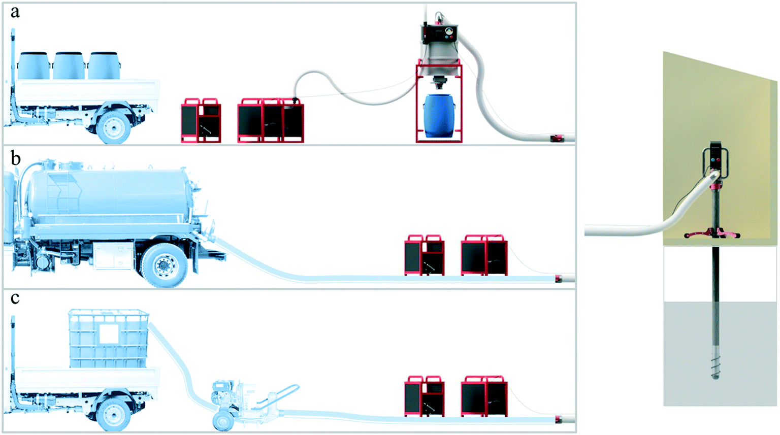 | ||
| Fig. 4 The Excluder (right) can be linked to a) a custom vacuum system (Flexcrevator), b) vacuum truck, or c) a pit-side pump. | ||
3.8. Time-motion study
The trash excluding attachment (design F) showed promise in emptying pits quickly when attached to either a custom vacuum system (the Flexcrevator) or a vacuum truck. When the trash excluding attachment was linked to the Flexcrevator, the total processing time was 57.4 minutes, with barrel management as the most time-consuming step in the process (Table 6). In contrast, when the vacuum truck was connected to the trash excluding attachment, the total process time decreased to 17.4 minutes, a ∼70% decrease in emptying time (Table 6). Linking the trash excluding attachment to the truck was more efficient because: (1) the storage capacity of the truck is larger than that of multiple barrels, and (2) handling barrels required more effort and time for setting up and cleaning. Thus, a vacuum truck (or a larger capacity system that eliminates barrels) with a Clearing Head has the greatest potential in emptying pits safely in the shortest time.| System configuration | Set-up (min) | Active pumping (min) | Barrel management (min) | Cleaning (min) | Total process (min) | Max. volume per trip to the treatment plant (m3) |
|---|---|---|---|---|---|---|
| Custom vacuum system | 11 | 3.4 | 27 | 16 | 57.4 | 0.81 |
| Vacuum truck | 7 | 2.4 | N/A | 8 | 17.4 | 8 |
3.9. Trash exclusion – potential benefits and challenges
Pit latrine emptying is a dangerous and undignified job, and a large percentage of the work of pit emptiers is manual handling of trash and sludge. A successful pit emptying machine needs to handle varying viscosities of fecal sludge and different types and amounts of trash inside the pit latrine. We tested the concept of trash exclusion, where sludge is pumped while trash is prevented from entering and clogging the pipe, to reduce sanitation workers' direct exposure to sludge and solid waste.The concept of trash exclusion is not new: screens have been part of pump inlets in water and sludge removal systems. However, screens in the pit latrine context are quickly rendered useless by pieces of trash that block flow. Active trash exclusion, using the auger clearing head reported in this study, is an innovative approach that continuously clears the screen and allows continuous pumping regardless of configuration (e.g., portable vacuums or vacuum trucks). At the end of the fecal sludge emptying process, the trash is left behind in the pit. This represents a change to current practice and can be seen as a disadvantage, as most household customers expect their pits to be completely emptied of fecal sludge as well as trash. However, we argue that pit latrines are designed for fecal sludge, and not for disposing of trash or household solid waste. The contract for pit emptying should be specifically for removal of fecal sludge; removing solid waste after the pit is emptied is a different task. Understandably, this is a departure from current practice in many communities that use pit latrines, and it would require changes in both household behavior and infrastructure (i.e., solid waste management in the communities). However, rather than seeing this as a disadvantage, we see trash exclusion as enabling these changes to occur. For example, changes in behavior (not disposing of household waste in the pit) may be incentivized by new business models that separate pit emptying from solid waste handling (and require separate fees). This would also lead to pressure for governments to support and provide solid waste management services and infrastructure. These new business models need to be tested in real communities. An additional advantage of trash exclusion is that downstream processing (treatment, reuse, or disposal) of fecal sludge is more efficient and cost effective. As it is, separation of sludge from trash often occurs at the fecal sludge treatment facility, if the sludge treatment process cannot handle trash (e.g., anaerobic digestion). Thus, trash separation occurs anyway, with the cost borne by the fecal sludge facility. Although continuous refinement of both technology and business models are needed, this study shows that trash exclusion has potential in making mechanized pit emptying feasible in pits with variable levels of trash.
4. Conclusions
A comprehensive design and prototyping effort, coupled to laboratory and field tests, resulted in a design for excluding trash during pit emptying. The clearing head design with a stationary screen and a rotating auger appears to be the most promising mechanism for dealing with trash. Prototypes successfully emptied water at 3.5 L s−1 and thick sludge at 2.4 L s−1 in laboratory tests. In the field, the average flow rate was up to 5.6 L s−1 in thin sludge. Thick sludge in real-world pits remains a challenge with low flow rates ∼ 0.2 L s−1. Despite the low flow rates, the trash excluding attachment successfully excluded trash items such as plastic bags, hair, and cloth.Based on the lab and field tests, we developed a new pit emptying technology based on the clearing head design (design K). The Flexcrevator + Excluder will allow pit emptying workers to increase their efficiency and improve their working environment by preventing their exposure to unsafe and unhealthy conditions. The most efficient configuration appears to be a combination of a vacuum truck and the Excluder, which allows the emptying of pits without “fishing.” Alternatively, a pit-side pump that empties sludge into a bigger container may be a lower cost configuration. The potential benefits and challenges of using trash exclusion during mechanized emptying of pit latrines was discussed, and future studies are needed to understand how to best integrate this system into pit latrine emptying businesses.
5. Author contributions
GFP: investigation, data curation, formal analysis, methodology, writing -original draft; TWR and WB: conceptualization, investigation, formal analysis, methodology. JT: data curation, project administration, validation, writing – review and editing. PO and NW: conceptualization, investigation, methodology, visualization. FdlR: conceptualization, formal analysis, funding acquisition, investigation, methodology, supervision, writing- review and editing.Conflicts of interest
FdlR, TW, and WB have a pending patent on the Excluder technology, under NC State University. The other co-authors declare no conflicting interests.Acknowledgements
This work was supported by the Bill & Melinda Gates Foundation, Seattle, WA [OPP1094923]. Data is publicly available at http://www.lib.ncsu.edu/resolver/1840.20/36929.References
- J. P. Graham and M. L. Polizzotto, Pit latrines and their impacts on groundwater quality: A systematic review, Environ. Health Perspect., 2013, 121, 521–530 CrossRef PubMed.
- N. Greene, S. Hennessy, T. W. Rogers, J. Tsai and F. L. de los Reyes III, The role of emptying services in provision of safely managed sanitation: A classification and quantification of the needs of LMICs, J. Environ. Manage., 2021, 290, 112612 CrossRef PubMed.
- W. C. Chipeta, R. H. Holm, J. F. Kamanula, W. E. Mtonga and F. L. de los Reyes, Designing local solutions for emptying pit latrines in low-income urban settlements (Malawi), Phys. Chem. Earth, 2017, 100, 336–342 CrossRef CAS PubMed.
- S. Chowdhury and D. Kone, Business Analysis of Fecal Sludge Management: Emptying and Transportation Services in Africa and Asia, The Bill & Melinda Gates Foundation, 2012 Search PubMed.
- J. Bhagwan, D. Still, C. A. Buckley and K. Foxon, When last did we look down the pits?, Water Institute of South Africa, Midrand, South Africa, 2008 Search PubMed.
- S. Bongi and A. Morel, Understanding Small Scale Providers of Sanitation Services : A Case Study of Kibera, Water and Sanitation Program, Nairobi, Kenya, 2005 Search PubMed.
- K. Eales, Bringing pit emptying out of the darkness : A comparison of approaches in Durban, South Africa, and Kibera, Kenya, BPD Water and Sanitation, London, United Kingdom, 2005 Search PubMed.
- Y. P. Thye, M. R. Templeton and M. Ali, A critical review of technologies for pit latrine emptying in developing countries, Crit. Rev. Environ. Sci. Technol., 2011, 41, 1793–1819 CrossRef.
- M. S. Muller and J. Rijnsburger, MAPET - A neighbourhood based pit emptying service with locally manufactured handpump equipment in Dar es Salaam, Tanzania, WASTE, Gouda, The Netherlands, 1992 Search PubMed.
- G. Mikhael, D. Robbins, J. E. Ramsay and M. Mbéguéré, in Faecal Sludge Management: Systematic Approach for Implementation and Operation, ed. L. Strande, M. Ronteltap and D. Brdjanovic, IWA Publishing, London, United Kingdom, 1st edn., 2014, pp. 67–96 Search PubMed.
- M. Kariuki, B. Collignon, R. R. Taisne and V. Bruno, Better Water and Sanitation for the Urban Poor: Good Practice from sub-Saharan Africa, European Communities and Water Utilities Partnership, Kenya, 2003 Search PubMed.
- D. Still and M. O'Riordan, The development of pit emptying technologies, Water Research Commission, Gezina, South Africa, 2012 Search PubMed.
- T. W. Rogers, F. L. de los Reyes III, W. J. Beckwith and R. C. Borden, Power earth auger modification for waste extraction from pit latrines, J. Water, Sanit. Hyg. Dev., 2014, 4, 72–80 CrossRef.
- R. H. Holm, J. Madalitso Tembo and B. Thole, A comparative study of faecal sludge management in Malawi and Zambia: Status, challenges and opportunities in pit latrine emptying, Afr. J. Environ. Sci. Technol., 2015, 9, 783–792 CrossRef.
- C. Niwagaba, M. Mbéguéré and L. Strande, in Faecal Sludge Management: Systems Approach for Implementation and Operation, ed. L. Strande, M. Ronteltap and D. Brdjanovic, IWA Publishing, London, United Kingdom, 1st edn., 2014, pp. 19–44 Search PubMed.
- D. Still and K. Foxon, Understanding Sludge Accumulation in VIPs and Strategies for Emptying Full Pits, Water Research Commission, Gezina, South Africa, 2012, vol. 1 Search PubMed.
- C. J. Brouckaert, K. M. Foxon and K. Wood, Modelling the filling rate of pit latrines, Water SA, 2013, 39, 555–562 Search PubMed.
- D. A. Still, After the Pit Latrine is full... What then? Effective Options for Pit Latrine Management, WISA Biennial Conference, Publication of Pollution Research Group, South Africa: University of Kwa Zulu Natal, 2002 Search PubMed.
- T. Sisco, T. Rogers, W. Beckwith, W. Chipeta, R. H. Holm, C. A. Buckley and F. L. de los Reyes, Trash removal methods for improved mechanical emptying of pit latrines using a screw auger, J. Water, Sanit. Hyg. Dev., 2017, 7, 7 Search PubMed.
- J. T. Radford, C. Underdown, K. Velkushanova, A. Byrne, D. P. K. Smith, R. A. Fenner, J. Pietrovito and A. Whitesell, Faecal sludge simulants to aid the development of desludging technologies, J. Water, Sanit. Hyg. Dev., 2015, 5, 456–464 CrossRef.
Footnote |
| † Electronic supplementary information (ESI) available. See DOI: 10.1039/d1ew00383f |
| This journal is © The Royal Society of Chemistry 2021 |