
MOF-derived hierarchical CoP nanoflakes anchored on vertically erected graphene scaffolds as self-supported and flexible hosts for lithium–sulfur batteries†
Jia
Jin‡
a,
Wenlong
Cai‡
b,
Jingsheng
Cai‡
a,
Yuanlong
Shao
c,
Yingze
Song
 a,
Zhou
Xia
a,
Qiang
Zhang
*b and
Jingyu
Sun
*a
a,
Zhou
Xia
a,
Qiang
Zhang
*b and
Jingyu
Sun
*a
aCollege of Energy, Soochow Institute for Energy and Materials InnovationS (SIEMIS), Key Laboratory of Advanced Carbon Materials and Wearable Energy Technologies of Jiangsu Province, Soochow University, Suzhou 215006, P. R. China. E-mail: sunjy86@suda.edu.cn
bBeijing Key Laboratory of Green Chemical Reaction Engineering and Technology, Department of Chemical Engineering, Tsinghua University, Beijing 100084, P. R. China. E-mail: zhang-qiang@mails.tsinghua.edu.cn
cPhysical Sciences and Engineering Division, King Abdullah University of Science and Technology, Thuwal, 23955-6900, Saudi Arabia
First published on 14th January 2020
Abstract
Lithium–sulfur (Li–S) batteries have garnered a lot of attention in the realm of electrochemical energy storage owing to their high energy and low cost. However, the serious polysulfide shuttle effect of the sulfur cathode poses a critical challenge for the development of Li–S batteries with elevated sulfur loadings. In addition, the poor robustness of traditional blade-casting cathodes greatly impedes the practical applications of flexible Li–S cells that display high areal capacity. To address these concerns, we report herein a freestanding hybrid sulfur host via in situ crafting of flexible carbon cloth (CC), vertically grown graphene nanoflakes over CC (G/CC) and metal–organic-framework derived CoP anchored on vertical graphene (CoP@G/CC). The thus-derived sulfur cathodes (CoP@G/CC-S) with a typical sulfur loading of 2 mg cm−2 exhibit outstanding electrochemical performances, including excellent rate capability (930.1 mA h g−1 at 3.0C) and impressive cycling stability (0.03% capacity decay per cycle after 500 cycles at 2.0C). A high areal capacity of 8.81 mA h cm−2 at 0.05C can also be obtained even at an elevated sulfur loading of 10.83 mg cm−2. Furthermore, flexible pouch cells based on the self-supported CoP@G/CC-S showcase favorable rate and cycling performances with high mechanical robustness.
Introduction
Lithium–sulfur (Li–S) batteries have emerged as a promising alternative to traditional lithium-ion batteries because of their cost-effectiveness, high theoretical capacity (1672 mA h g−1) and environmental benignity.1–5 Despite these multiple merits, the practical applications of Li–S batteries are still hindered by several major drawbacks, including limited electrical conductivity of elemental sulfur, severe lithium polysulfide (LiPS) shuttling and discernible volume changes upon cycling.6–11 These would inevitably lead to low sulfur utilization, sluggish reaction kinetics and hence retarded electrochemical performances.12,13 Therefore, effective strategies for the sulfur host design are required to achieve the suppression of LiPS shuttling and retention of active materials.14–18Recent years have seen significant progress in the fabrication of hybrid sulfur hosts that synergize the physical/chemical capture and electrocatalytic conversion of LiPSs.19–21 The thus-derived cathodes are normally prepared by virtue of the slurry coating method, where considerable amounts of conductive additives and binders need to be incorporated to augment the electrical conductivity and sulfur loading.22 However, this would not only induce a large number of cracks within the thick electrodes but also undermine the energy density of the cells. Moreover, the coated electrodes possess limited robustness, thereby making it difficult to construct flexible Li–S batteries.23,24 In this context, utilizing conductive and flexible carbon cloth to load sulfur has attracted growing attention in the realm of high-performance cathode design. Zhong et al. demonstrated a porous carbon fiber/VN integrated scaffold as a highly conductive and binder-free sulfur host with enhanced rate capability.25 Yang et al. proposed the decoration of an amorphous CoS3 electrocatalyst onto nitrogen-doped carbon nanotube/carbon paper for promoting the transformation from Li2S2 to Li2S.26 Wang and colleagues fabricated carbon-encapsulated CoP nanosheet array covered carbon cloth as a composite sulfur host, which afforded suppressed shuttle effects and outstanding specific capacities at different current densities.27 Despite these exciting achievements, the design of flexible, well-defined and high-performance cathodes based on carbon cloth is still at its nascent stage. In addition, key issues pertaining to reaction kinetics and sulfur loadings necessitate an in-depth investigation.
Herein, we present a self-supported and binder-free sulfur cathode via in situ integration of flexible and conductive carbon cloth (CC), vertically grown graphene nanoflakes over CC (G/CC), metal–organic-framework (MOF) derived CoP uniformly anchored on vertical graphene (CoP@G/CC), and active sulfur species by impregnation (CoP@G/CC-S). Such a hybrid cathode exhibits a full suite of unique features. First, the three-dimensional porous graphene vertically grown on CC not only offers an excellent conductive network for carrier transport and electrolyte penetration, but also well accommodates sulfur species and the related volume changes to ensure a high loading of active material.28,29 Second, the CoP nanostructures derived on vertical graphene synergize the efficient immobilization and effective electrocatalytic interaction of LiPSs, thereby restraining the shuttle effect and promoting the redox kinetics to attain large capacities under high rates with low voltage polarizations. Benefiting from these merits, the designed CoP@G/CC-S cathode delivers a high specific capacity of 1195.0 mA h g−1 at 0.5C and retains 1135.0 mA h g−1 after 150 cycles. It also achieves an extended cycle life at 2.0C (1044.9 mA h g−1 after 500 cycles accompanying a low capacity decay of 0.03% per cycle). Even at an elevated sulfur loading of 10.83 mg cm−2, such a cathode retains a high areal capacity of 8.81 mA h cm−2 at 0.05C.
Experimental methods
Preparation of G/CC
The freestanding G/CC was prepared by using a PECVD route. In detail, a piece of carbon cloth was placed within the CVD furnace chamber near a remote plasma generator. The chamber pressure was pumped to 3.0 Pa, and pure argon with a flow rate of 500 sccm was used to clean the chamber for 15 min. Along with the temperature ramping, the argon flow rate was set at 100 sccm. When the temperature reached 550 °C, CH4 (10 sccm) was introduced in the presence of plasma. The growth time was set at 30 min.Preparation of CoP@CC
2-Methylimidazole and Co(NO3)2·6H2O were respectively dissolved in 40 mL deionized water and the resulting mixture was stirred for 15 min. The two solutions were then mixed and stirred for another 30 min to form solution A. A piece of carbon cloth was dipped into solution A to allow the growth of ZIF-L(Co) for 4 h. The thus-synthesized ZIF-L(Co)/CC was washed and dried, followed by annealing in Ar at 700 °C for 3 h to produce Co/CC. Subsequently, NaH2PO2 as the phosphating agent was placed upstream of the tube furnace, and Co/CC was placed downstream. The phosphorization treatment was conducted in Ar at 300 °C for 3 h, with the heating rate maintained at 2 °C per minute.Preparation of CoP@G/CC
The as-obtained G/CC was firstly treated with a gentle O2 plasma to make the surface hydrophilic and then soaked in solution A for 4 h. CoP@G/CC was obtained according to the aforementioned route.Fabrication of the self-supported sulfur cathode
For a typical sulfur loading, 0.25 g sulfur was dissolved in 5 mL CS2 to form a uniform solution. The prepared solution was then evenly dropped onto CC, G/CC, CoP@CC and CoP@G/CC hosts, followed by keeping at 155 °C for 12 h in a confined space. Afterwards, the self-supported sulfur cathodes were maintained in an oven at 200 °C for 2 h to reduce the residue sticking on the outer surface. With respect to an elevated sulfur loading, larger amounts of sulfur can be used.Visualized adsorption tests
Li2S4 solution with a concentration of 3.5 mmol L−1 was prepared by dissolving stoichiometric amounts of sulfur and Li2S in 1,2-dimethoxyethane by stirring. A certain amount of pure CC, G/CC, CoP@CC and CoP@G/CC was added into 2 mL Li2S4 solution, respectively, followed by a gentle shake for 15 s. The whole process was carried out in a glovebox filled with argon gas and compared with pure Li2S4 solution.Symmetric cell assembly and measurements
Li2S6 symmetrical cells were assembled in a glovebox filled with argon gas. G, CoP and CoP@G were loaded on carbon paper (CP) disks and denoted as G/CP, CoP@CP and CoP@G/CP, respectively. Two identical electrodes (G/CP, CoP@CC or CoP@G/CC) were assembled into a CR2032 coin cell with a Celgard 2400 membrane serving as the separator. 40 μL Li2S6 solution (0.6 M) was used as the electrolyte. The Li2S6 solution was prepared by dissolving sulfur and lithium sulfide at a molar ratio of 5![[thin space (1/6-em)]](https://www.rsc.org/images/entities/char_2009.gif) :1 into a mixture of dimethoxyethane/1,3-dioxolane containing LiTFSI (0.5 mol L−1) and 0.5 wt% LiNO3. CV measurements of symmetric cells were performed at a scan rate of 50 mV s−1 within the potential range of −1.0 to 1.0 V. Note that CV tests of these symmetric cells at a scan rate of 0.5 mV s−1 in the potential range of −1.0 to 1.0 V were based on the employment of less concentrated Li2S6 solution as the electrolyte (0.2 M).
:1 into a mixture of dimethoxyethane/1,3-dioxolane containing LiTFSI (0.5 mol L−1) and 0.5 wt% LiNO3. CV measurements of symmetric cells were performed at a scan rate of 50 mV s−1 within the potential range of −1.0 to 1.0 V. Note that CV tests of these symmetric cells at a scan rate of 0.5 mV s−1 in the potential range of −1.0 to 1.0 V were based on the employment of less concentrated Li2S6 solution as the electrolyte (0.2 M).
Li2S nucleation tests
First, Li2S8 solution with a concentration of 0.2 mol L−1 was prepared by dissolving sulfur and Li2S at a molar ratio of 7:1 in a tetraglyme solution followed by vigorous stirring at 60 °C for 24 h. G, CoP and CoP@G were dissolved in ethanol and then dispersed on CP (13 mm) to obtain G/CP, CoP@CP and CoP@G/CP, respectively. The battery was composed of G/CP, CoP@CP or CoP@G/CP as the positive electrode, lithium as the negative electrode and Celgard 2400 membrane as the separator. 20 μL Li2S8 (0.2 mol L−1) used as the electrolyte was added into the cathode and 20 μL LiTFSI (0.5 mol L−1) was added into the anode side. Then the batteries were galvanostatically discharged up to 2.05 V at 0.112 mA and then held potentiostatically at 2.05 V for Li2S to nucleate and grow until the current decreased to below 10−5 A.
Characterization
The morphologies and the corresponding elemental mapping images were obtained using a Hitachi SU8010 scanning electron microscope (SEM) equipped with an energy-dispersive X-ray spectroscopy (EDS) system. X-ray diffraction (XRD) patterns of the composites were obtained using a Bruker D8 Advance diffractometer. X-ray photoelectron spectroscopy (XPS) spectra were recorded using an Escalab 250Xi spectrophotometer.Electrochemical measurements
A standard CR2032 coin cell was assembled in a glovebox filled with argon gas. The cathodes were prepared by cutting CC-S, G/CC-S, CoP@CC-S and CoP@G/CC-S into a circular disk with a diameter of 13 mm. The battery was assembled with the prepared CC-S, G/CC-S, CoP@CC-S or CoP@G/CC-S as the positive electrode, lithium foil as the negative electrode and Celgard 2400 membrane as the separator. The electrolyte was made up of 0.5 mol L−1 LiTFSI and 0.5 wt% LiNO3 in a mixed solution of dimethoxyethane/1,3-dioxolane. The electrolyte/sulfur ratio remained at 12 μL mg−1 for cathodes with high sulfur loadings. The galvanostatic charge/discharge profiles were collected, and rate performance and cycling performance were studied on a LAND CT2001A battery testing system in a voltage range of 1.7–2.8 V. Cyclic voltammetry (CV) and electrochemical impedance spectroscopy (EIS) curves were obtained on an Autolab potentiostat (PGSTAT302N).Results and discussion
Fig. 1a illustrates the preparation process of the self-supported CoP@G/CC-S cathode. First, vertically erected graphene nanoflake arrays can be grown on the CC substrate via a plasma-enhanced chemical vapor deposition (PECVD) route to form G/CC. Then cobalt-based ZIF-L(Co) was uniformly anchored onto the surface of the G/CC support (ZIF-L(Co)@G/CC). Upon mild carbonization–phosphorization treatment in an Ar environment, CoP@G/CC can be further derived. Such a flexible sulfur host allows for direct sulfur impregnation with a tailorable loading amount, leading to the formation of the CoP@G/CC-S cathode. The morphological features of various stage products during this process were systematically inspected by employing scanning electron microscopy (SEM). It is evident that pristine CC displays a quite smooth surface structure (Fig. 1b and c). During the PECVD process, vertically erected graphene nanoflakes can be uniformly grown on CC substrates (G/CC). SEM images indicate that these vertical graphene structures cross-link with each other to enable an interconnected network, offering extra space for accommodating active materials (Fig. 1d and e, and S1, ESI†). After wet-chemical MOF fabrication, ZIF-L(Co) arrays are further derived in a homogeneous manner, as depicted in Fig. 1f and g. Finally, the as-prepared ZIF-L(Co)@G/CC samples experience a carbonization–phosphorization step to produce the self-supported CoP@G/CC electrode (Fig. 1h and i, and S2, ESI†). Moreover, CoP@CC can also be produced in a controllable fashion (Fig. S3, ESI†).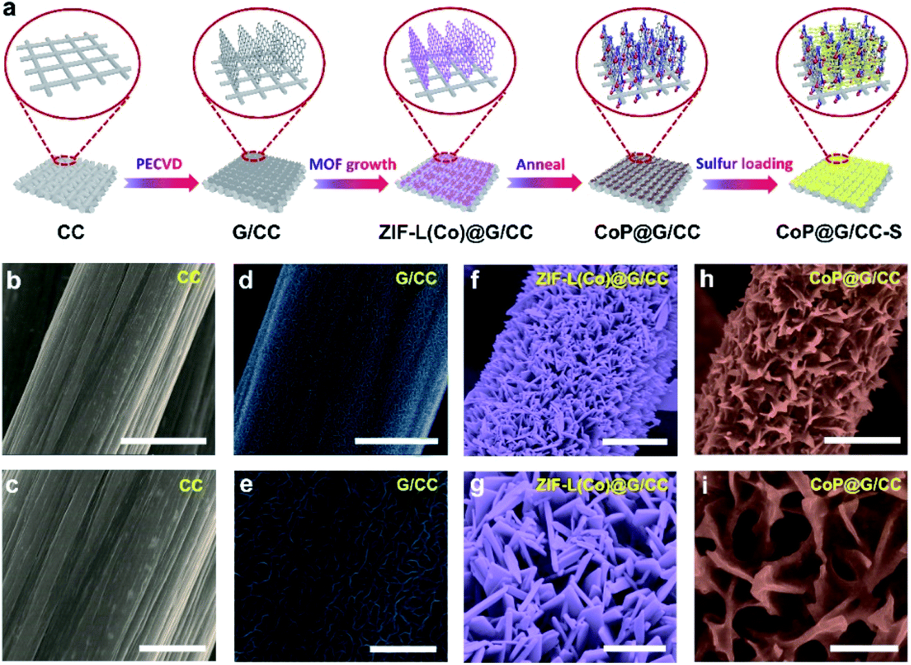 | ||
| Fig. 1 (a) Schematic illustration of the fabrication process of the self-supported CoP@G/CC-S cathode. SEM images of (b and c) CC, (d and e) G/CC, (f and g) ZIF-L(Co)@G/CC and (h and i) CoP@G/CC hosts. Scale bars: (b, d, f, and h) 5 μm and (c, e, g, i) 2 μm. | ||
Transmission electron microscopy (TEM) was employed to probe the detailed morphology of the thus-designed CoP@G/CC. Fig. 2a displays a low magnification TEM view, readily manifesting the covering of a single carbon fiber by layers of nanosheets. A close observation of Fig. 2b reveals that the wrapping layer has a porous nature, which is beneficial for the rapid transport of electrons and ions. Note that the interlayer spacing of vertical graphene (∼0.34 nm) can be universally identified. Fig. 2c further presents the high-resolution TEM micrograph of the examined sample. The distances between adjacent lattice planes (d-spacing) are measured to be ∼0.196 and 0.282 nm, corresponding to the (112) and (011) planes of CoP, respectively.30 Moreover, elemental mapping images in a scanning transmission electron microscopy (STEM) mode reveal the uniform distribution of C, O, P and Co elements over the CoP@G/CC surface (Fig. 2d). X-ray diffraction (XRD) and X-ray photoelectron spectroscopy (XPS) measurements were performed to inspect the detailed crystal phase and chemical composition of the CoP@G/CC composite. Fig. 2e shows the representative XRD patterns of CoP@G/CC and CoP@CC samples, where the main peaks for both can be well indexed to the CoP phase (JCPDS no. 29-0497).31,32 As for CoP@G/CC, along with the CoP signals, the broad diffraction peak at 26.5° corresponds to the (002) plane of graphitic carbon. XRD patterns of the bare CC, G/CC and ZIF-L(Co)/CC were further collected (Fig. S4 and S5, ESI†), and they indicate the formation of vertical graphene and ZIF-L(Co) species on CC.33Fig. 2f displays the XPS Co 2p spectrum of CoP@G/CC, which originates from three main contributions, Co–P (778.8 eV), Co–O (782.1 eV) and a satellite peak (786.1 eV).34Fig. 2g shows that the XPS P 2p spectrum of CoP@G/CC could be divided into two peaks, corresponding to P–O (133.8 eV) and Co–P (129.9 eV), respectively.35 It is noted that the XPS full-scan spectrum indicates the existence of Co, P, C and O elements (Fig. S6, ESI†). To test the adsorption capability of CoP@G/CC with respect to LiPSs, a visualized adsorption experiment was performed in parallel by dosing an identical amount of CC, G/CC, CoP@CC, or CoP@G/CC into a prepared Li2S4 solution (3.5 mmol L−1). As shown in the digital photograph in Fig. 2h, CoP@CC and CoP@G/CC manage to decolor the Li2S4 solution in 3 h, suggesting favorable LiPS adsorption.36 In this respect, XPS characterization was carried out to further probe the chemical interactions between Li2S4 and CoP@G/CC. Upon adsorption, Co–S bonding, P–S bonding and P–Li bonding can be witnessed in the Co 2p and P 2p spectra (Fig. S7, ESI†).37 There are two pairs of peaks in the S 2p spectrum, which can also be observed for bare Li2S4, located at 161.18 and 162.68 eV, corresponding to the terminal S (ST−1) and bridging S (S0B), respectively.38 In contrast, these peaks present a discernible shift to higher binding energy after interacting with CoP@G/CC. Moreover, thiosulfate species appear in the S 2p spectrum, which might be beneficial for accelerated Li2S nucleation and improved sulfur utilization on CoP@G/CC.39–41
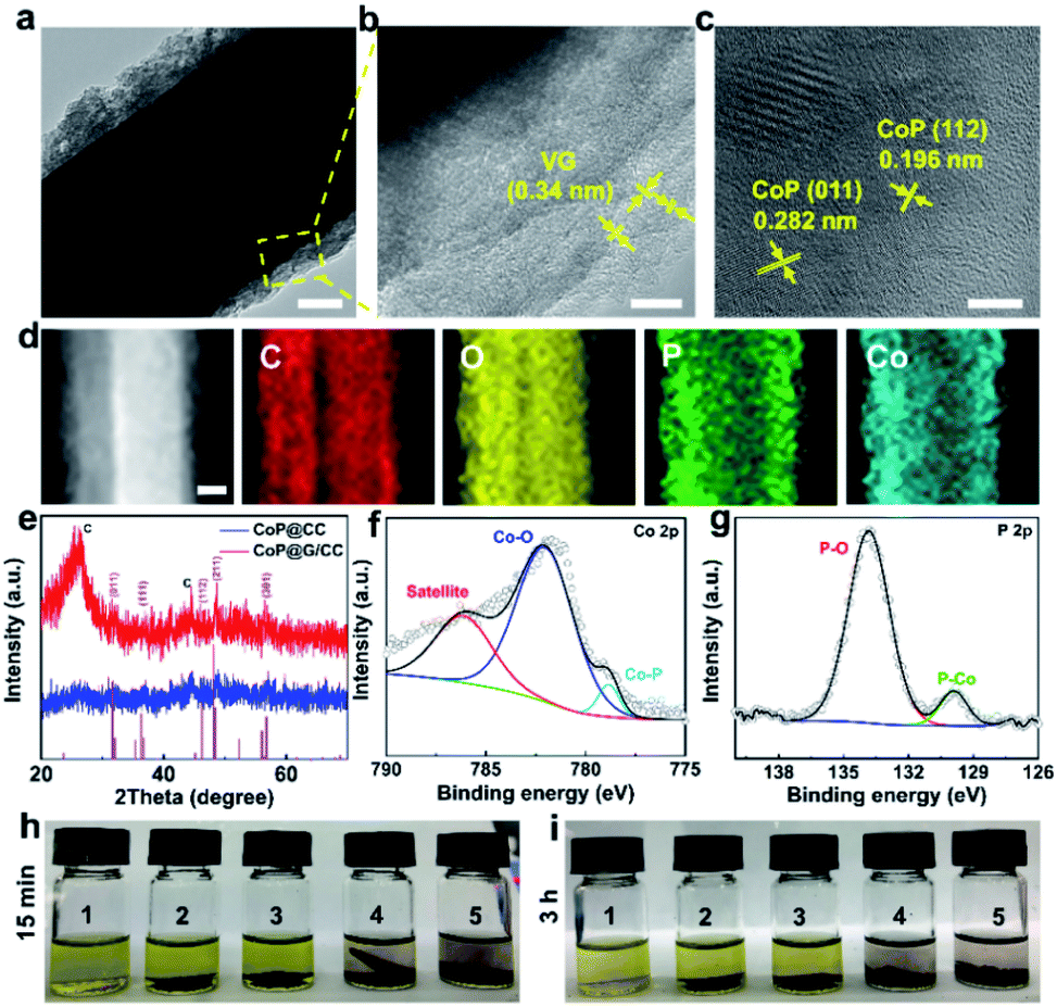 | ||
| Fig. 2 (a) Low magnification TEM image of the CoP@G/CC composite. Scale bar: 100 nm. (b) TEM image of CoP@G/CC. Scale bar: 10 nm. (c) HRTEM image. Scale bar: 5 nm. (d) STEM image and elemental maps of CoP@G/CC. Scale bar: 100 nm. (e) XRD patterns of CoP@G/CC and CoP@CC. (f and g) Co 2p and P 2p XPS spectra of CoP@G/CC, respectively. (h and i) Digital photographs from the Li2S4 adsorption test. 1: bare Li2S4 solution; 2: CC-Li2S4; 3: G/CC-Li2S4; 4: CoP@CC-Li2S4; 5: CoP@G/CC-Li2S4. | ||
The sulfur active material was impregnated into the self-supported hosts by drop-casting S/CS2 solution, thereby obtaining sulfur cathodes of CC-S, G/CC-S, CoP@CC-S and CoP@G/CC-S (Fig. S8, ESI†). Note that such a process was repeated to ensure a uniform distribution of sulfur in the cathodes, which gives rise to a typical sulfur loading of 1.8–2.5 mg cm−2. Energy dispersive X-ray (EDS) mapping images reveal the homogeneous distribution of Co, O, P, C and S elements within the CoP@G/CC-S cathodes (Fig. S9 and S10, ESI†). The thus-derived cathodes were subjected to a suite of electrochemical characterizations to evaluate their electrochemical properties. Fig. 3a shows cyclic voltammetry (CV) profiles of CC-S, G/CC-S, CoP@CC-S and CoP@G/CC-S in a voltage window of 1.7–2.8 V at a scan rate of 0.05 mV s−1. The two cathodic peaks appearing at 2.2–2.4 V (Peak i) and 2.0–2.1 V (Peak ii) could be attributed to the reduction of S8 to soluble long chain LiPSs, and further reduction of these LiPSs to insoluble short chain Li2S2/Li2S, respectively. The anodic peak at 2.3–2.5 V (Peak iii) is ascribed to the oxidation of Li2S/Li2S2 back to S8. In particular, the CoP@G/CC-S cathode shows a positive shift to a higher potential for the reduction peak (Peak i) and a negative shift to a lower potential for the oxidation peak (Peak iii), implying facile sulfur redox reactions induced by the CoP–vertical graphene heterostructure. Fig. 3b presents the electrochemical impedance spectroscopy (EIS) profiles of CC-S, G/CC-S, CoP@CC-S and CoP@G/CC-S cathodes. It is evident that the CoP@G/CC-S cathode possesses the smallest charge transfer resistance and more favorable ion diffusion properties. Fig. 3c shows the CV curves of symmetric cells tested at 50 mV s−1 between −1.0 V and 1.0 V. Such symmetrical cells were constructed by using bare CP, G/CP, CoP@CP and CoP@G/CP as two parallel electrodes with the addition of Li2S6-containing electrolyte. The CV of bare CP cells with Li2S6-free electrolyte was measured as the control to calibrate the capacitive contributions.42 As indicated by the black line, the capacitive contribution is trivial. As such, CoP@G/CP possesses a higher Li2S6 redox current in comparison with those of G/CP and CoP@CP, suggesting superior catalytic performance.
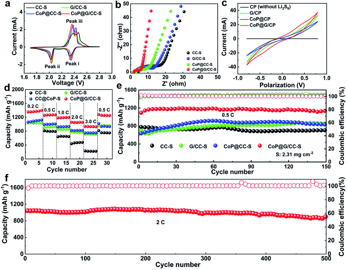 | ||
| Fig. 3 (a) CV profiles of CC-S, G/CC-S, CoP@CC-S and CoP@G/CC-S cathodes. (b) EIS profiles. (c) CV curves of Li2S6 symmetric cells using CP, G/CP, CoP@CP and CoP@G/CP electrodes in the electrolytes with and without 0.6 M Li2S6 at 50 mV s−1. (d) Rate capabilities of CC-S, G/CC-S, CoP@CC-S and CoP@G/CC-S cathodes. (e) Cycling performances of CC-S, G/CC-S, CoP@CC-S and CoP@G/CC-S cathodes at 0.5C. (f) Long-term cycling performances of CoP@G/CC-S cathodes at 2.0C. | ||
Fig. 3d compares the rate capabilities of CC-S, G/CC-S, CoP@CC-S and CoP@G/CC-S cathodes by augmenting the current density from 0.2C to 3.0C every 5 cycles and returning it to 0.5C (1.0C = 1672 mA g−1). Apparently, CoP@G/CC-S cathodes manifest advanced rate performance, delivering average capacities of 1371.9, 1265.5, 1189.6, 1053.1 and 930.1 mA h g−1 at 0.2, 0.5, 1.0, 2.0 and 3.0C, respectively. When the current density returns to 0.5C, a comparably high capacity of 1258.7 mA h g−1 can be restored. Such an outstanding rate capability compares favorably with that of other reported self-supporting cathodes in Li–S systems (Table S1†). Fig. 3e shows the cycling performances of CC-S, G/CC-S, CoP@CC-S and CoP@G/CC-S cathodes at a relatively low current density of 0.5C (Fig. S11, ESI†). Note that at the beginning of the cycle, the electrolyte needs sufficient time to fully penetrate into the thick CC-enabled electrode, as evidenced by the continuous elevation of capacities in the initial cycles. After 150 cycles, the CoP@G/CC-S cathode achieves a stable cycling performance with almost no capacity attenuation. Moreover, the cycling performances at 0.2C were also investigated. It was found that higher capacity accompanied by smaller voltage polarization of the CoP@G/CC-S cathode can be achieved relative to its counterparts (Fig. S12, ESI†). At a relatively high rate of 2.0C, our CoP@G/CC-S cathode delivers a high initial capacity of 1044.9 mA h g−1 and maintains a low capacity decay of only 0.03% per cycle for 500 cycles (Fig. 3f), which benefits from the favorable electrical conductivity and effective polysulfide regulation.
To probe the catalytic effect of CoP@G/CC hybrid hosts for Li–S chemistry, Li-ion diffusion and LiPS conversion processes were systematically studied. As for exploring the Li-ion diffusion behavior, different self-supported electrodes were subjected to CV scans at various sweep rates from 0.1 to 0.5 mV s−1 (Fig. S13, ESI†). All the cathodic and anodic peak currents for the tested cathodes display a linear relationship with the square root of sweep rates, wherein the classical Randles–Sevcik equation can be employed to describe the Li-ion diffusivity: Ip = (2.69 × 10⁵)n1.5AD0.5CLiν0.5. In this equation, Ip is the peak current, n is the charge transfer number, A is the area of the active cathode, D is the Li-ion diffusion coefficient, CLi is the concentration of lithium ions in the cathode, and ν is the sweep rate.43 Accordingly, the slopes of the curve plotted in Fig. 4a–c represent the diffusion rates of lithium ions. It can be clearly observed that the CoP@G/CC-S cathode presents faster Li-ion diffusion features in contrast to the other tested cathodes, indicative of better reaction kinetics for sulfur redox.44
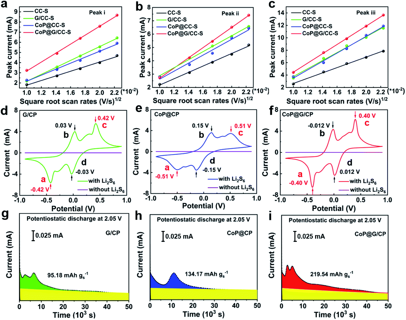 | ||
| Fig. 4 (a–c) Reaction kinetics with respect to the Li+ ion diffusion properties of CC-S, G/CC-S, CoP@CC-S and CoP@G/CC-S cathodes at various scan rates. (d–f) CV profiles of symmetric cells of G/CP, CoP@CP and CoP@G/CP in electrolytes with and without 0.2 M Li2S6 at 0.5 mV s−1. (g–i) Potentiostatic discharge profiles of a Li2S8/tetraglyme solution on various surfaces at 2.05 V. | ||
To further explore the catalyzing function of the CoP@G/CC hybrid with respect to the Li–S redox reactions, CV profiles of G/CP, CoP@CP and CoP@G/CP symmetric cells were collected in the presence/absence of Li2S6 electrolyte (0.2 mol L−1) at a scan rate of 0.5 mV s−1. As depicted in Fig. 4d–f, all compounds with the Li2S6 electrolyte display two pairs of redox signals, corresponding to peaks a, b, c, and d. Peak a reflects the reduction of Li2S6 to Li2S and peak d implies the reduction of S8 to Li2S6; the peaks of b and c are the reverse processes of peaks d and a, respectively.45 The narrow peak separation for the redox pair and sharp peak intensity would imply facile polysulfide conversion and favorable electrochemical reversibility.46 Obviously, CoP@G/CP possesses advanced electrochemical activity amongst the three systems. Moreover, the conversion kinetics of LiPSs were assessed via Li2S precipitation tests. The potentiostatic discharge profiles of a Li2S8/tetraglyme solution at 2.05 V were collected for graphene, CoP and CoP@G (Fig. 4g–i). The precipitation capacity on CoP@G (219.6 mA h g−1) remains apparently larger than those on bare graphene (95.2 mA h g−1) and CoP (134.2 mA h g−1), indicating higher activity toward LiPS conversion.47,48 Post-mortem SEM images after Li2S nucleation show that the CoP@G/CP surface presents almost full coverage of Li2S precipitation, in stark contrast to the scenarios of G/CP and CoP@CP (Fig. S14, ESI†). The foregoing analysis clearly demonstrates that CoP@G/CC hybrid hosts with optimized morphological, compositional and electronic architectures not only enhance the adsorption ability for LiPSs but also facilitate the LiPS conversion process en route to advanced electrochemical performance.
The surface reaction process of the CoP@G/CC-S cathode was examined by XPS before and after cycling, as shown in Fig. S15, ESI.† The initial XPS S 2p spectrum before cycling is mainly associated with the S8 species. After 100 cycles, sulfate and thiosulfate signals dominate the S 2p spectrum, along with the detection of the Li2S signal. Note that the peak strength of the thiosulfate species is lower than that of the sulfate, indicating that the thiosulfate is formed first and then gradually converted to sulfate upon cycling.39,40,49 Thus, the evolution of S8 at the CoP@G/CC host can be illustrated (Fig. S16, ESI†). A post-mortem SEM inspection of the various cathodes after 100 cycles at 0.2C reveals the good structural stability and high robustness of G/CC-S and CoP@G/CC-S cathodes upon electrochemical cycling (Fig. S17, ESI†). This observation again corroborates the special merits of the in situ built, vertically erected graphene arrays in boosting the electrode conductivity, maintaining the elevated sulfur loading and buffering the volume changes (Fig. S18, ESI†).
Furthermore, Li–S batteries possessing elevated sulfur loadings were evaluated. It is noted that the electrolyte volume/sulfur mass ratio (E/S) was set at ca. 12 μL mg−1. Fig. 5a displays the cycling performances of CC-S, CoP@CC-S and CoP@G/CC-S cathodes with a sulfur loading of 4.62 mg cm−2 at 0.1C. Apparently, the CoP@G/CC-S cathode delivers the highest capacity within the entire cycle range. Note that the observed fluctuation of capacity values could be attributed to the gradual penetration of electrolyte into the thick sulfur electrode upon cycling. So, CoP@G/CC-S cathodes with higher loadings (∼9.55 and ∼10.83 mg cm−2) were additionally assembled. Cross-sectional SEM/EDS characterization of the thick cathodes with a sulfur loading of 10.83 mg cm−2 suggests a uniform distribution of sulfur (Fig. S19, ESI†). At a sulfur loading of 9.55 mg cm−2, the cathode manifests excellent cycling performance at 0.1C for 60 cycles after the activation at 0.05C for the first cycle (Fig. 5b). Moreover, the cathode with a loading of 10.83 mg cm−2 displays a high areal capacity of 8.81 mA h cm−2 at 0.05C (Fig. 5c), which is higher than that of commercial lithium-ion batteries (4.0 mA h cm−2).
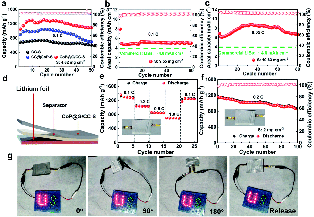 | ||
| Fig. 5 (a) Cycling performances of the CC-S, CoP@CC-S and CoP@G/CC-S cathodes at 0.1C with a sulfur mass loading of ∼4.62 mg cm−2. Cycling performances of CoP@G/CC-S cathodes with sulfur loadings of (b) 9.55 mg cm−2 at 0.1C and (c) 10.83 mg cm−2 at 0.05C. (d) Schematic diagram of the Li–S pouch cell. (e and f) Rate and cycling performances of the pouch cell. (g) Digital photographs showing the mechanical flexibility of the pouch cell in bent and released states (0°, 90°, 180°, and release). | ||
To illustrate the practical applications of our CoP@G/CC-S cathodes for future wearable Li–S batteries, proof-of-concept pouch cells were accordingly constructed by sequentially sealing the self-supported CoP@G/CC-S electrode, separator and lithium ribbon. Fig. 5d shows the schematic diagram of our pouch cell. The effective area of the cathodes is 9 cm2, and the sulfur loading of the pouch cell is ∼2 mg cm−2. Fig. 5e showcases the rate performances by augmenting the current density from 0.1C to 1.0C every 5 cycles and returning it to 0.1C. The pouch cell enables reversible capacities of 1359.0, 1036.0, 856.0 and 698.0 mA h g−1 at 0.1, 0.2, 0.5 and 1.0C, respectively (with the corresponding galvanostatic charge/discharge profiles shown in Fig. S20, ESI†). When the current density returns to 0.1C, a capacity of 1251.0 mA h g−1 can still be recovered. Fig. 5f presents the cycling performance of the assembled pouch cells at 0.2C. A high initial capacity of 1151.6 mA h g−1 can be obtained. After 100 cycles, the capacity can still be retained at 860.6 mA h g−1. The favorable rate capability and cycling stability benefit from the elevated electrical conductivity and restrained polysulfide shuttling of CoP@G/CC-S electrodes. A performance comparison between pouch cells in this work and state-of-the-art reports is further drawn (Table S2†). To demonstrate the real applications, a light-emitting diode (LED) panel consisting of 26 LED lights was powered by the assembled flexible pouch cell in various bent states. Fig. 5g displays digital photographs of stable illumination of the LED panel. In addition, the cycling performance of the pouch cell in bent and released states was also tested (Fig. S21, ESI†), showing the outstanding robustness and flexibility of our Li–S pouch cell targeting wearable energy storage applications.50
Conclusion
In conclusion, we have successfully designed a self-supported, flexible and binder-free CoP@G/CC sulfur host. Such a hybrid architecture not only offers an excellent conductive network and ample surface area but also achieves strong LiPS immobilization and conversion efficiency, thereby realizing rapid electron/ion transport, high sulfur loading, effective volume buffering and suppressed polysulfide shuttling. Consequently, the CoP@G/CC-S cathode presents an impressive capacity of 1195.0 mA h g−1 at 0.5C and retains 1135.0 mA h g−1 after 150 cycles. Even at an elevated sulfur loading of 10.83 mg cm−2, such a cathode retains a high areal capacity of 8.81 mA h cm−2. Of particular note, the robust features of such self-supported cathodes enable the construction of flexible Li–S pouch cells that manifest favorable electrochemical properties under mechanical deformations. This would ultimately inspire the development of high-performance flexible and wearable energy storage devices.Conflicts of interest
There are no conflicts to declare.Acknowledgements
This work was supported by the National Natural Science Foundation of China (51702225 and 21825501), National Key Research and Development Program (2016YFA0200103, 2016YFA0202500 and 2016YFA0200102), and Natural Science Foundation of Jiangsu Province (BK20170336). The authors acknowledge the support from Suzhou Key Laboratory for Advanced Carbon Materials and Wearable Energy Technologies, Suzhou, China.Notes and references
- X. Ji, K. T. Lee and L. F. Nazar, Nat. Mater., 2009, 8, 500–506 CrossRef CAS PubMed.
- Z. W. Seh, Y. Sun, Q. Zhang and Y. Cui, Chem. Soc. Rev., 2016, 45, 5605–5634 RSC.
- M. Wild, L. O'Neill, T. Zhang, R. Purkayastha, G. Minton, M. Marinescu and G. J. Offer, Energy Environ. Sci., 2015, 8, 3477–3494 RSC.
- X. Yang, X. Li, K. Adair, H. Zhang and X. Sun, Electrochem. Energy Rev., 2018, 1, 239–293 CrossRef CAS.
- Z. Li, H. B. Wu and X. W. Lou, Energy Environ. Sci., 2016, 9, 3061–3070 RSC.
- Y. J. Li, J. M. Fan, M. S. Zheng and Q. F. Dong, Energy Environ. Sci., 2016, 9, 1998–2004 RSC.
- Q. Pang, X. Liang, C. Y. Kwok and L. F. Nazar, Nat. Energy, 2016, 1, 16132 CAS.
- H. J. Peng, J. Q. Huang and Q. Zhang, Chem. Soc. Rev., 2017, 46, 5237–5288 RSC.
- Y. Yang, G. Zheng, S. Misra, J. Nelson, M. F. Toney and Y. Cui, J. Am. Chem. Soc., 2012, 134, 15387–15394 CrossRef CAS PubMed.
- C. Ye, L. Zhang, C. Guo, D. Li, A. Vasileff, H. Wang and S. Z. Qiao, Adv. Funct. Mater., 2017, 27, 1702524 CrossRef.
- Z. Li, J. Zhang, B. Guan, D. Wang, L. M. Liu and X. W. Lou, Nat. Commun., 2016, 7, 13065 CrossRef CAS PubMed.
- Y. Song, W. Cai, L. Kong, J. Cai, Q. Zhang and J. Sun, Adv. Energy Mater., 2020 DOI:10.1002/aenm.201901075.
- J. Zhang, Z. Li and X. W. D. Lou, Angew. Chem., Int. Ed., 2017, 56, 14107–14112 CrossRef CAS PubMed.
- H. J. Peng, J. Q. Huang, X. B. Cheng and Q. Zhang, Adv. Energy Mater., 2017, 7, 1700260 CrossRef.
- Y. Song, W. Zhao, N. Wei, L. Zhang, F. Ding, Z. Liu and J. Sun, Nano Energy, 2018, 53, 432–439 CrossRef CAS.
- J. He, W. Lv, Y. Chen, J. Xiong, K. Wen, C. Xu, W. Zhang, Y. Li, W. Qin and W. He, J. Mater. Chem. A, 2018, 6, 10466–10473 RSC.
- H. Yuan, X. Chen, G. Zhou, W. Zhang, J. Luo, H. Huang, Y. Gan, C. Liang, Y. Xia, J. Zhang, J. Wang and X. Tao, ACS Energy Lett., 2017, 2, 1711–1719 CrossRef CAS.
- S. Huang, Y. V. Lim, X. Zhang, Y. Wang, Y. Zheng, D. Kong, M. Ding, S. A. Yang and H. Y. Yang, Nano Energy, 2018, 51, 340–348 CrossRef CAS.
- Y. Song, W. Zhao, L. Kong, L. Zhang, X. Zhu, Y. Shao, F. Ding, Q. Zhang, J. Sun and Z. Liu, Energy Environ. Sci., 2018, 11, 2620–2630 RSC.
- Z. Yuan, H. J. Peng, J. Q. Huang, X. Y. Liu, D. W. Wang, X. B. Cheng and Q. Zhang, Adv. Funct. Mater., 2014, 24, 6105–6112 CrossRef CAS.
- J. Zhang, Z. Li, Y. Chen, S. Gao and X. W. D. Lou, Angew. Chem., Int. Ed., 2018, 57, 10944–10948 CrossRef CAS PubMed.
- P. G. Bruce, S. A. Freunberger, L. J. Hardwick and J. M. Tarascon, Nat. Mater., 2011, 11, 19–29 CrossRef PubMed.
- Q. Pang, X. Liang, C. Y. Kwok, J. Kulisch and L. F. Nazar, Adv. Energy Mater., 2016, 7, 1601630 CrossRef.
- W. Xue, Z. Shi, L. Suo, C. Wang, Z. Wang, H. Wang, K. P. So, A. Maurano, D. Yu, Y. Chen, L. Qie, Z. Zhu, G. Xu, J. Kong and J. Li, Nat. Energy, 2019, 4, 374–382 CrossRef CAS.
- Y. Zhong, D. Chao, S. Deng, J. Zhan, R. Fang, Y. Xia, Y. Wang, X. Wang, X. Xia and J. Tu, Adv. Funct. Mater., 2018, 28, 1706391 CrossRef.
- X. Yang, X. Gao, Q. Sun, S. P. Jand, Y. Yu, Y. Zhao, X. Li, K. Adair, L. Y. Kuo, J. Rohrer, J. Liang, X. Lin, M. N. Banis, Y. Hu, H. Zhang, X. Li, R. Li, H. Zhang, P. Kaghazchi, T. K. Sham and X. Sun, Adv. Mater., 2019, 31, 1901220 CrossRef PubMed.
- Z. Wang, J. Shen, J. Liu, X. Xu, Z. Liu, R. Hu, L. Yang, Y. Feng, J. Liu, Z. Shi, L. Ouyang, Y. Yu and M. Zhu, Adv. Mater., 2019, 31, 1902228 CrossRef PubMed.
- B. Li, S. Li, J. Liu, B. Wang and S. Yang, Nano Lett., 2015, 15, 3073–3079 CrossRef CAS PubMed.
- X. Xiao, P. Liu, J. S. Wang, M. W. Verbrugge and M. P. Balogh, Electrochem. Commun., 2011, 13, 209–212 CrossRef CAS.
- C. Tang, R. Zhang, W. Lu, L. He, X. Jiang, A. M. Asiri and X. Sun, Adv. Mater., 2017, 29, 1602441 CrossRef PubMed.
- L. Jiao, Y. X. Zhou and H. L. Jiang, Chem. Sci., 2016, 7, 1690–1695 RSC.
- Q. Liu, J. Tian, W. Cui, P. Jiang, N. Cheng, A. M. Asiri and X. Sun, Angew. Chem., Int. Ed., 2014, 53, 6710–6714 CrossRef CAS PubMed.
- J. Zhang, T. Zhang, D. Yu, K. Xiao and Y. Hong, CrystEngComm, 2015, 17, 8212–8215 RSC.
- Y. Zhong, L. Yin, P. He, W. Liu, Z. Wu and H. Wang, J. Am. Chem. Soc., 2018, 140, 1455–1459 CrossRef CAS PubMed.
- X. Chen, X. Ding, C. Wang, Z. Feng, L. Xu, X. Gao, Y. Zhai and D. Wang, Nanoscale, 2018, 10, 13694–13701 RSC.
- Y. Song, W. Zhao, X. Zhu, L. Zhang, Q. Li, F. Ding, Z. Liu and J. Sun, ACS Appl. Mater. Interfaces, 2018, 10, 15733–15741 CrossRef CAS PubMed.
- J. Cheng, D. Zhao, L. Fan, X. Wu, M. Wang, N. Zhang and K. Sun, J. Mater. Chem. A, 2017, 5, 14519–14524 RSC.
- L. Jin, G. Li, B. Liu, Z. Li, J. Zheng and J. P. Zheng, J. Power Sources, 2017, 355, 147–153 CrossRef CAS.
- H. Tang, W. Li, L. Pan, C. P. Cullen, Y. Liu, A. Pakdel, D. Long, J. Yang, N. McEvoy, G. S. Duesberg, V. Nicolosi and C. J. Zhang, Adv. Sci., 2018, 5, 1800502 CrossRef PubMed.
- H. Tang, W. Li, L. Pan, K. Tu, F. Du, T. Qiu, J. Yang, C. P. Cullen, N. McEvoy and C. Zhang, Adv. Funct. Mater., 2019, 29, 1901907 CrossRef.
- W. Cai, G. Li, D. Luo, G. Xiao, S. Zhu, Y. Zhao, Z. Chen, Y. Zhu and Y. Qian, Adv. Energy Mater., 2018, 8, 1802561 CrossRef.
- W. Yang, W. Yang, L. Dong, X. Gao, G. Wang and G. Shao, J. Mater. Chem. A, 2019, 7, 13103–13112 RSC.
- G. Zhou, H. Tian, Y. Jin, X. Tao, B. Liu, R. Zhang, Z. W. Seh, D. Zhuo, Y. Liu, J. Sun, J. Zhao, C. Zu, D. S. Wu, Q. Zhang and Y. Cui, Proc. Natl. Acad. Sci. U. S. A., 2017, 114, 840–845 CrossRef CAS PubMed.
- X. Zhu, W. Zhao, Y. Song, Q. Li, F. Ding, J. Sun, L. Zhang and Z. Liu, Adv. Energy Mater., 2018, 8, 1800201 CrossRef.
- J. Zhou, X. Liu, L. Zhu, J. Zhou, Y. Guan, L. Chen, S. Niu, J. Cai, D. Sun, Y. Zhu, J. Du, G. Wang and Y. Qian, Joule, 2018, 2, 2681–2693 CrossRef CAS.
- N. Wang, B. Chen, K. Qin, E. Liu, C. Shi, C. He and N. Zhao, Nano Energy, 2019, 60, 332–339 CrossRef CAS.
- Y. Song, Z. Sun, J. Cai, N. Wei, M. Wang, Y. Shao, Z. Liu and J. Sun, J. Mater. Chem. A, 2019, 7, 20750–20759 RSC.
- H. J. Peng, G. Zhang, X. Chen, Z. W. Zhang, W. T. Xu, J. Q. Huang and Q. Zhang, Angew. Chem., Int. Ed., 2016, 55, 12990–12995 CrossRef CAS PubMed.
- S. Wang, J. Liao, X. Yang, J. Liang, Q. Sun, J. Liang, F. Zhao, A. Koo, F. Kong, Y. Yao, X. Gao, M. Wu, S. Z. Yang, R. Li and X. Sun, Nano Energy, 2019, 57, 230–240 CrossRef CAS.
- C. Li, S. Cong, Z. Tian, Y. Song, L. Yu, C. Lu, Y. Shao, J. Li, G. Zou, M. H. Rümmeli, S. Dou, J. Sun and Z. Liu, Nano Energy, 2019, 60, 247–256 CrossRef CAS.
Footnotes |
| † Electronic supplementary information (ESI) available: Additional characterization and electrochemical measurements. See DOI: 10.1039/c9ta13046b |
| ‡ These authors contributed equally to this work. |
| This journal is © The Royal Society of Chemistry 2020 |