
 Open Access Article
 This Open Access Article is licensed under a
 Creative Commons Attribution 3.0 Unported Licence
Squeezed nanocrystals: equilibrium configuration of metal clusters embedded beneath the surface of a layered material†
Scott E.
Julien‡
a,
Ann
Lii-Rosales‡
 bc,
Kai-Tak
Wan
a,
Yong
Han
bd,
Michael C.
Tringides
bd,
James W.
Evans
bd and
Patricia A.
Thiel
*bce
bc,
Kai-Tak
Wan
a,
Yong
Han
bd,
Michael C.
Tringides
bd,
James W.
Evans
bd and
Patricia A.
Thiel
*bce
aMechanical and Industrial Engineering, Northeastern University, Boston, MA 02115, USA
bAmes Laboratory, Ames, Iowa 50011, USA. E-mail: pthiel@ameslab.gov
cDepartment of Chemistry, Iowa State University, Ames, IA 50011, USA
dDepartment of Physics and Astronomy, Iowa State University, Ames, IA 50011, USA
eDepartment of Materials Science and Engineering, Iowa State University, Ames, IA 50011, USA
First published on 11th March 2019
Abstract
Shapes of functional metallic nanocrystals, typically synthesized either free in solution or supported on surfaces, are key for controlling properties. Here, we consider a novel new class of metallic nanocrystals, copper clusters embedded near the surface of graphite, which can be considered a model system for metals embedded beneath surfaces of layered materials, or beneath supported membranes. We develop a continuum elasticity (CE) model for the equilibrium shape of these islands, and compare its predictions with experimental data. The CE model incorporates appropriate surface energy, adhesion energies, and strain energy. The agreement between the CE model and the data is—with one exception—excellent, both qualitatively and quantitatively, and is achieved with a single adjustable parameter. The model predicts that the embedded island shape is invariant with size, manifest both by constant side slope and by constant aspect ratio. This prediction is rationalized by dimensional analysis of the relevant energetic contributions. The aspect ratio (width![[thin space (1/6-em)]](https://www.rsc.org/images/entities/char_2009.gif) :height) of an embedded Cu cluster is much larger than that of a supported but non-embedded Cu cluster, due to resistance of the graphene membrane to deformation. Experimental data diverge from the model predictions only in the case of the aspect ratio of small islands, below a critical height of ∼10 nm. The divergence may be due to bending strain, which is treated only approximately in the model. Strong support for the CE model and its interpretation is provided by additional data for embedded Fe clusters. Most of these observations and insights should be generally applicable to systems where a metal cluster is embedded beneath a layered material or supported membrane, provided that shape equilibration is possible.
:height) of an embedded Cu cluster is much larger than that of a supported but non-embedded Cu cluster, due to resistance of the graphene membrane to deformation. Experimental data diverge from the model predictions only in the case of the aspect ratio of small islands, below a critical height of ∼10 nm. The divergence may be due to bending strain, which is treated only approximately in the model. Strong support for the CE model and its interpretation is provided by additional data for embedded Fe clusters. Most of these observations and insights should be generally applicable to systems where a metal cluster is embedded beneath a layered material or supported membrane, provided that shape equilibration is possible.
Introduction
The structures and shapes of functional nanocrystals (NCs) are key to determining their properties. Synthesis can lead to deviations from equilibrium structure, sometimes dramatic and sometimes desired to tune properties.1–3 However, characterization of equilibrium structure is an essential initial step in understanding and manipulating these systems. Distinct traditional classes of NCs include unsupported three-dimensional (3D) NCs obtained, e.g., via solution phase synthesis, and supported two-dimensional (2D) and 3D NCs formed during deposition on top of substrates. The classic Wulff construction based on surface energetics describes the equilibrium shape of unsupported NCs,4 and a 2D analogue or Winterbottom modification treats 2D and 3D supported NCs, respectively.2 For quantum dots (supported 3D NCs formed due to lattice mismatch in heteroepitaxy), strain effects are also critical in controlling shape.5 Here, we consider a novel and distinct class of 3D NCs (also referred to as clusters) which are embedded beneath the surface of a layered material, and thus squeezed between a blanket of one or a few covering monolayers and the underlying semi-infinite stack of supporting layers.Such configurations are relevant to emergent technologies involving layered materials such as graphite, and their single- or few-layer derivatives such as graphene.6–8 For instance, in electronic devices, it will be important to place nanoscale metallic electrodes or heat sinks beneath or between such layered materials. There is also interest in confined catalysis under 2D materials, wherein the catalytic activity of a metal can be controlled by tailoring the microenvironment between the metal surface and the 2D cover.9,10 A good model for these configurations is provided by our recent discovery that 3D Cu nano-clusters can be grown beneath the topmost layer(s) of graphite under specific conditions.11,12
The goal of the present work is to develop and evaluate a continuum elasticity (CE) model that incorporates the strain energy of the top graphene layer, as well as adhesion and surface energies of the Cu, graphene, and graphite surfaces, which control the equilibrium shape of surface-encapsulated islands. Values of input parameters are derived from density functional theory (DFT) and from the literature. We then compare the predicted shapes, described in terms of dimensional ratios, against experimental values to determine whether the model is applicable.
Results and discussion
Review of experimental data
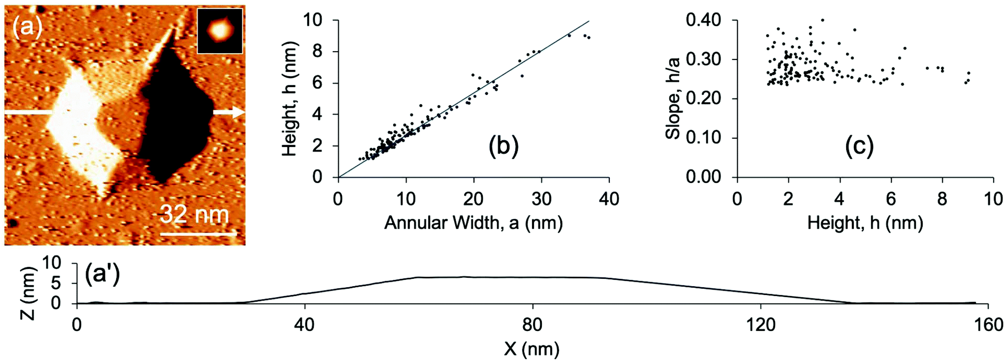
Experimentally, the Cu nanoislands are grown by a process in which Cu atoms impinge on a defect-rich graphite surface (where the defects have been introduced by bombardment with Ar+), penetrate through some of the defects, and nucleate beneath the graphite surface. During this process, the graphite substrate is held at elevated temperatures of 600–800 K. It is known that Cu islands supported on top of graphite begin to coarsen at 550–600 K,13 so Cu–Cu bond breaking must be facile at 600 K and above. It is thus credible that the Cu islands could assume equilibrium shapes when grown beneath the graphite surface at 600–800 K. In all data reported herein, Cu islands formed at 800 K.An example of such an island is shown in the scanning tunneling microscopy (STM) image and profile of Fig. 1(a and a′). Reviewing our earlier observations,11 we note that the central portion of the island is hexagonally faceted, with a flat top. This suggests that the central portion, at the top and the bottom, is bounded by (111) facets. Islands with rounded tops are also observed, but the present work is restricted to those with flat tops because the geometry of the encapsulated Cu is more clearly defined. The sides of the features are sloped, forming an annulus around the central region, and the carbon lattice can be atomically resolved on island tops as well as sloping sides. The data show that the carbon sheet atop the islands can have a thickness of several graphene monolayers (GMLs)—at least up to 3.11 Analysis of shapes in terms of the dimensions defined in Fig. 1b, shows that height h scales closely with width of the annulus a, i.e. the slope of the sides (h/a) is constant for different sizes. On the other hand, the diameter d scales poorly with h, i.e. the aspect ratio (d/h) is not constant. These relationships are shown in Fig. 1(c and d) for a dataset that encompasses 140 Cu islands. This is a significant expansion of the 55-island dataset presented in an earlier report.11 The above observations are unaffected, but the expansion allows more precise quantitative assessments.
 | ||
| Fig. 1 (a) STM image of a representative Cu cluster encapsulated beneath the graphite surface. The image has been derivatized to reveal edges more clearly. The inset shows a topographic version. (a′) Line profile (with common X- and Z-axis scales) of the Cu island, corresponding to the white horizontal arrow in (a). (b) Schematic diagram of the SLBT model and island dimensions. The inset shows a 3D representation of the model. (c) h vs. a for 140 Cu islands. (d) d vs. h for 140 Cu islands. | ||
Methods used to derive island dimensions from STM data, and to evaluate the model predictions, are described in the ESI.† Experimental details pertinent to sample preparation and interrogation have been presented elsewhere.11
The CE model
In the present work, we approximate the hexagonal footprint of the Cu island as a circle and treat the sides as vertical. Thus a cylindrical Cu cluster grows between a membrane consisting of one or more GMLs and a graphite substrate, as shown in Fig. 1b. The graphite substrate is assumed to be rigid, while the graphene blanket undergoes elastic stretching and bending deformations to accommodate the growing island. Going forward, we use the term island to mean the composite of the Cu cluster plus deformed graphene membrane and local graphite support, and the term Cu cluster to denote only the central metallic portion.The annulus is assumed to be an empty overhang, based on certain characteristics of the STM images. One is the shallow slope of the sides. This slope is much smaller than that of low-index (111) or (100) Cu planes which would naturally adjoin the top (111) facet for a supported Cu cluster. Thus, an annulus filled with Cu is not an energetically viable configuration as it would involve a high-index, high surface energy face of Cu. Another characteristic is the frequent presence of wrinkles (narrow extensions) of the annulus, one of which appears in the lower left corner of Fig. 1a. These wrinkles suggest that no restraining traction is exerted on the membrane by an underlying material, which would restrict it from folding.
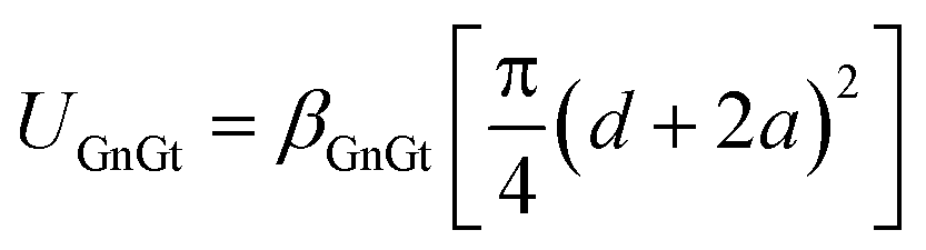
The energy of the system, Π, can be modeled as the sum of the elastic strain energy of the distorted graphene film, Ue, plus a set of terms that represent the interfacial and surface (IS) components of the total energy of the system. The relevant interfaces and surfaces are: clean Cu; graphene–graphite (GnGt); and Cu–graphene and Cu–graphite (together denoted CuG). The corresponding IS energy terms are: (i) energy costs associated with the Cu surface energy, UCu, and the loss of Gn–Gt adhesion, UGnGt; and (ii) energy reductions associated with Cu–Gn and Cu–Gt adhesion, UCuG. These are collectively called UIS terms, and all U-terms are defined as positive. The specific form of the total energy is shown in eqn (1), and is discussed more fully in the ESI.†
| Π = UCu + UGnGt − UCuG + Ue | (1) |
The equilibrium shape is obtained by minimizing Π for fixed Cu cluster volume V. We do not include terms in Π associated with the bulk Cu and graphite energies, or the total graphite surface energy before intercalation, as these are constant.
Calculation of interfacial and surface components of total energy
Each UIS term can be expressed as a sum of products of a surface energy, γ, or adhesion energy, β, times the corresponding area, thus relating each UIS term to one or more dimensions of the island, as given in Table 1. Using density functional theory (DFT), we have calculated the values for γ and β shown in Table 1.14 (Some details of these calculations are also provided in the ESI.†) The experimental data shows that the top and bottom of the Cu metal cluster have (111) orientation. The sides are undoubtedly faceted and have some contribution from higher-energy orientations, especially (100), but we expect that they are mostly (111) orientation and so we use γCu(111) for the cylindrical sides as well. With this information, calculation of the UIS terms is straightforward.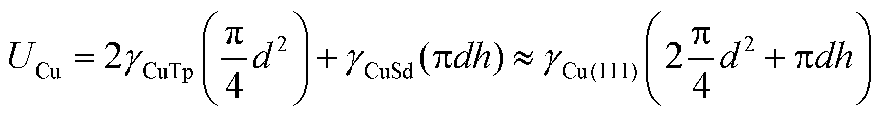

Calculation of strain component of the total energy
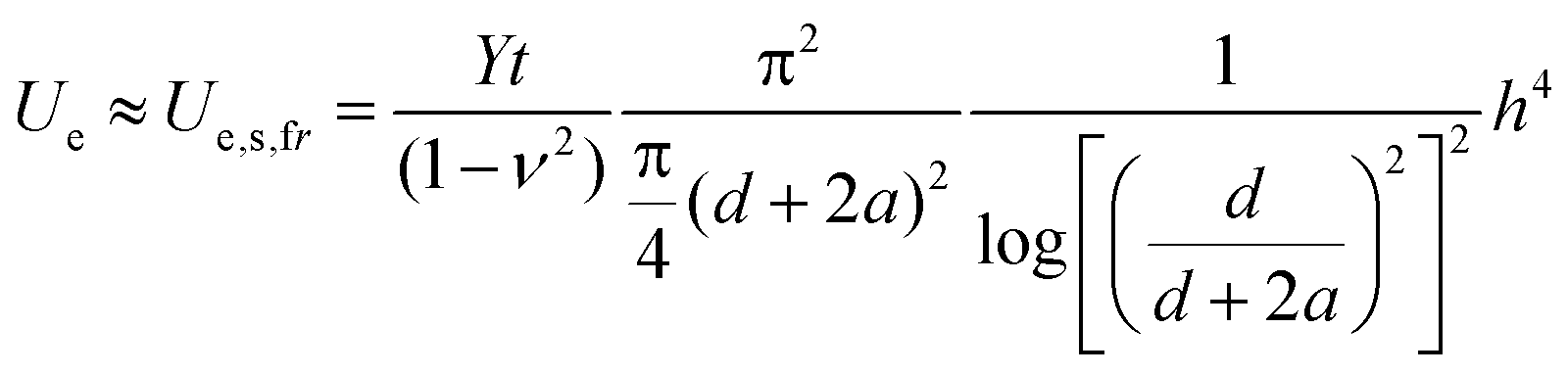
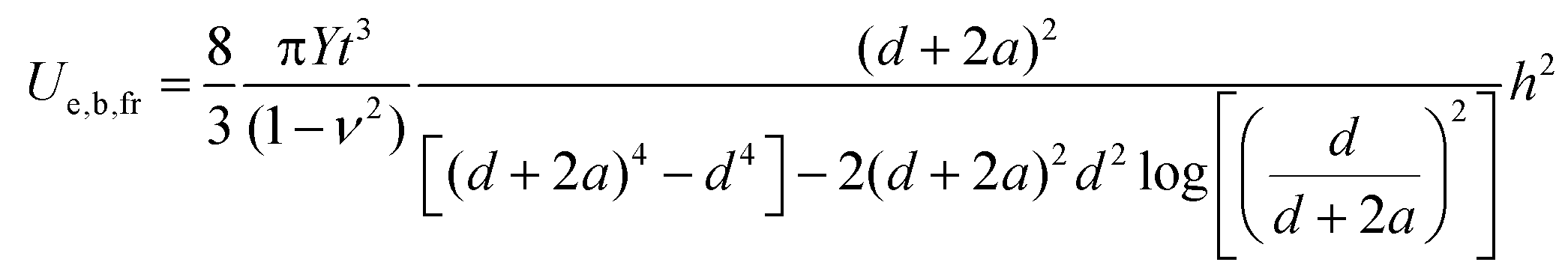
The Ue term can be obtained from the flat-ended cylindrical shaft-loaded blister test (SLBT) model, in which a cylindrical shaft moves upward through an aperture in a solid surface, pressing against and deforming an elastic membrane that adheres to the surface. It is an excellent model for the situation depicted in Fig. 1b, where Cu cluster growth exerts an upward pressure analogous to that of the SLBT shaft.The membrane undergoes both stretching and bending deformations. In the SLBT model with a cylindrical punch of finite (non-zero) diameter, these are approximated as independent contributions because an analytical solution considering both simultaneously is unavailable. Calculation of separate stretching and bending terms (Table 1) indicates that bending strain is insignificant over our range of experimental island sizes, so we will model the total elastic energy of the film, Ue, as due to stretching deformation only. On the other hand, an analytical solution is available in the limit of zero punch diameter (i.e. a “point load”) that includes both types of strain simultaneously. For this geometry, bending deformation must be included for deflections h < ∼5t.17,18 We will show later that 5t ≈5–7 nm in our system. A significant fraction of the experimental data falls below this limit. Although the point-load geometry is a poor approximation to the Cu island geometry, we cannot rule out the possibility that bending strain is significant for Cu islands below a critical height that falls within our experimental range.
For the SLBT model, we further consider two variants which differ in the distribution of strain in the graphene membrane. As an island grows, the annulus can respond without constraint, but adhesion between the portion of graphene atop the island and the Cu could inhibit lateral stretching of the graphene. If stretching is not inhibited, this portion is able to distort freely atop the island, and is modeled by a “free” SLBT wherein strain is distributed throughout the annulus and top region. At the other extreme, the top graphene could adhere so strongly that it is wholly prevented from stretching. This is modeled by the “clamped” SLBT, wherein strain is confined to the annulus. There are no analytical models for the intermediate case of partial interaction, but results would fall between these two limits. For purposes of first illustrating the general approach (below), we consider only the free SLBT, but the final analysis will show that results are very similar for the two models.
With these considerations in mind, eqn (5) in Table 1 is the expression we use for Ue of graphene for the SLBT.19 It shows that Ue depends on Poisson's ratio ν, elastic (Young's) modulus Y, and graphene thickness t. For ν the accepted value is 0.165—the value for graphite in the basal plane.16 For Y, a significant amount of variation is present among literature reports. Y has been characterized by a number of methods;15,20–24 of these, methods that use atomic force microscopy to deform a region of freestanding graphene most closely resemble the geometry and loading in the present work, pointing to Y ∼1 TPa.15,21,22 One of these studies showed that Y increases and then decreases as a function of defect density in graphene.15 The defect density in our work is (7.3 ± 0.4) × 103 μm−2, which corresponds to Y = 1.1 TPa from ref. 15, so we use this value here.
As noted earlier, experiment shows that graphene atop the islands can consist of more than 1 GML.11 We thus define the thickness of the top graphene as t = L·tGML, where L is the number of graphene layers and is treated as a fitting parameter. The term tGML is taken to be 0.34 nm, the interlayer spacing in crystalline graphite. We will later show that the best agreement with experiment is achieved, on average, with L = 3 to 4 (corresponding to 5t ≈5 to 7 nm). Until then, we use L = 4 to illustrate the general approach.
Analysis of Π at fixed V
Using the expressions for UIS and Ue and the input parameters summarized in Table 1, Π in eqn (1) becomes a function of only three independent variables: a, h, and d. The problem can be simplified further by fixing the cluster volume V = πhd2/4, which allows elimination of either h or d. Then the number of independent variables is two, i.e. Π = Π(a, h) or Π = Π(a, d). For illustration, we choose Π(a, h) and use the average volume determined from our dataset, 〈Vexp〉 = 4 × 10⁴ nm3.Fig. 2 shows Π(a, h) for this choice of V. Importantly, there is a clear minimum in Π, which is the equilibrium state. At the minimum, the CE model predicts that aeq = 38.8 nm, heq = 9.4 nm, and deq = 73.6 nm. For islands close to this 〈Vexp〉 (within ±20%), the experimental data show 〈aexp〉 = 31 ± 11 nm, 〈hexp〉 = 7.3 ± 2.6 nm, and 〈dexp〉 = 88 ± 21 nm. The two sets of numbers agree within the (large) experimental uncertainties.
 | ||
| Fig. 2 (a, b) Two views of the total potential energy surface, Π(a, h), for a cluster with V = 4.0 × 10⁴ nm3 and L = 4 in the free SLBT model. (c, d) Orthogonal cuts through this Π(a, h). (c) Fixed h = heq. (d) Fixed a = aeq. | ||
Fig. 2(c and d) show two orthogonal cuts through Π(a, h), each passing through the global minimum. Each graph shows not only Π, but also individual UIS and Ue terms. The shapes of these curves, and their relative magnitudes, are qualitatively independent of cluster volume over the full range of volumes, which spans about two orders of magnitude. This can be concluded by comparing analogous curves for volumes that fall near the upper and lower experimental limits, shown in the ESI.†
Analysis of equilibrium dimensions vs. V or h
The above process can be repeated over the entire range of experimentally observed cluster volumes (1.8 × 10³ nm3 ≤ V ≤ 6.9 × 10⁵ nm3). The variation of island dimensions with volume, predicted by the model, can thus be compared with experiment. The ESI† provides results in this format. We then convert the results to ratios of island dimensions vs. h, because this format facilitates direct comparison with experiment, and precludes uncertainty that would be introduced by translating experimental island dimensions into volumes. Fig. 3 shows h/a, d/h, and d/a both for theory and experiment. (Although d/a can be derived from the other two ratios, it is provided for completeness.)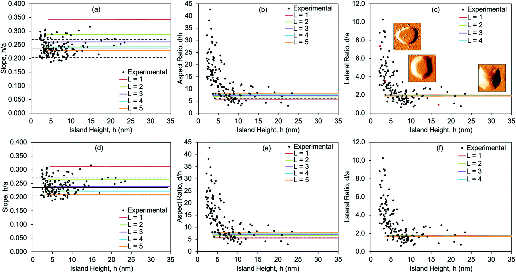 | ||
| Fig. 3 Experimental and theoretical dimension ratios h/a, d/h, and d/a, vs. h. Theoretical results are shown by colored lines for 1 ≤ L ≤ 5. Panels (a, b, c) give results for the free SLBT model, and (d, e, f) for the clamped SLBT model. In panels (a, d) the experimental average is the solid horizontal black line at h/a = 0.24, and the limits of ±1σ (the standard error) are shown by the dashed horizontal black lines. In panels (b, e) the experimental average of d/h = 7.3 for h > 10 nm is shown by the dashed horizontal black line. Panel (c) also shows STM images of islands to illustrate the difference in d/a. Red data points correspond to STM image insets. The STM image sizes in panel (c), from highest d/a to lowest d/a, are: 105 × 105 nm2; 80 × 80 nm2; 250 × 250 nm2. | ||
For h/a, the experimental values are constant at 0.24 ± 0.03 across the entire range of island size. Remarkably, the theoretical results predict a constant h/a value across the experimental range of island size as well. The theoretical results for h/a are shown for 1 ≤ L ≤ 5. The best agreement, on average, is at L = 4, although there is no reason to expect that all islands have the same value of L in experiment and so implying that the data should be fit with a single value of L is probably misleading. Indeed, variation in L could contribute to the scatter in the experimental data. For the free SLBT (Fig. 3a–c), the theoretical result for L = 1 lies well outside the upper limit of the range of experimental data, however, and can be excluded. At present it is unclear why the Cu clusters are buried beneath multiple graphene layers, but this conclusion is supported both by previous11 and present analyses.
The experimental aspect ratio d/h (and d/a in parallel) follows a different trend, one that was not identified previously from simply inspecting d vs. h in Fig. 1d or ref. 11. As shown in Fig. 3b, the experimental value of d/h starts at a high value around 40. It then falls steeply with increasing h up to h ≈ 10 nm, whereupon it levels off at d/h = 7.3 ± 2.8, represented by the horizontal dashed line. This asymptotic value is in excellent agreement with the d/h values predicted from the model, which are 5.6 to 8.0 for L = 1 to 5. However, the model fails to reproduce the strong variation in d/h at smaller h, which will be addressed later.
For the clamped SLBT (Fig. 3d–f), trends in the theoretical results are very similar to the free SLBT, i.e. h/a and d/h are constant with h, and L = 1 is again inconsistent with experiment. The only significant difference is that, for a given L, the ratio h/a for the clamped SLBT tends to be slightly lower than for the free SLBT. Consequently, best agreement is achieved for L = 3 in the clamped model rather than L = 4 in the free model. The difference is reasonable, as the free portion of the graphene film atop the island in the free SLBT allows the stress in the film to be distributed throughout a larger area, reducing stress in the annular overhang. In the clamped SLBT, by contrast, stress is confined to the annular portion. This makes the annular graphene more “taut”, which causes the graphene to delaminate from the graphite to a slightly larger value of a.
Discussion
Returning to Fig. 2(c and d), we note that the position of the minimum in Π is determined by those energy terms which have highest curvature in the vicinity of the minimum. Hence inspection of Fig. 2c shows that Ue and UGnGt determine aeq, while UCu and UCuG do not. Physically, this means that aeq depends on the mechanical properties of the graphene membrane and its adhesion to the graphite substrate—and does not depend on the nature of the metal or the metal cluster's diameter. Delamination in the annulus is purely a response to the upward displacement, h, of the membrane at the inner circumference of the annulus. If this picture is correct, then a size-invariant value of h/a, close to the value observed for Cu, should also be observed for other metals that form encapsulated clusters similar to Cu.Fig. 4 provides data to test this hypothesis. Iron can form encapsulated clusters on the surface of graphite that are very similar to encapsulated clusters of Cu, shown by the example in Fig. 4a. The variation of h with a, and of h/a with h, is shown in Fig. 4(b and c). Indeed, the value of h/a for Fe is size-independent, with a value of 0.28 ± 0.04. This is the same—within experimental error—as the value for Cu, 0.24 ± 0.03. The similarity between Fe and Cu provides strong evidence for the validity of our model and interpretation.
 | ||
| Fig. 4 (a) A representative STM image (derivatized) of an Fe cluster encapsulated at the graphite surface. The inset shows a topographic version. (a′) Line profile (with common X- and Z-axis scales) of the Fe island. (b) h vs. a for 140 Fe islands. The straight line is a least-squares fit constrained to pass through the origin. (c) h/a vs. h for 140 Fe islands. | ||
Similar logic can be applied to identify the energy terms that influence heq. Here, Fig. 2d shows that all terms contribute, but those with highest curvature near the minimum are UCu and Ue. The involvement of the UCu term indicates that the value of heq predicted by the model should be metal-dependent. Notably, the strong increase of Ue with h limits the island height, even though the value of Ue is small at the minimum. In other words, the resistance of the graphene membrane to strain strongly inhibits upward growth of the Cu clusters, leading to rather flat islands with high aspect ratio, d/h.
For comparison, we have recently performed a Winterbottom analysis of the equilibrium crystal shape (ECS) of a Cu cluster supported on top of graphite (sans graphene membrane), using the DFT energies listed in Table 1.14 The Winterbottom analysis yielded d/h = 0.8–0.9. This is much smaller than the average value of 7.3 ± 2.8 for the encapsulated Cu islands, in the regime of large h where the equilibrium model agrees with the data. We conclude that, at equilibrium, encapsulated Cu islands on graphite are much flatter than non-encapsulated ones, and this is due to resistance to strain in the overlying graphene membrane.
The model predicts that h/a and d/h are size-independent, and this has a clear ramification: the profile of a shape-equilibrated encapsulated Cu island is size-invariant, just as the ECS of a free (or supported) solid crystalline particle is size-invariant above the atomistic limit. This result can be understood from an analysis of the relevant energetics, given by the formulae in Table 1. We introduce a characteristic linear dimension, D, for the cluster so that, e.g., a = αD, d = δD, and h = ηD. Then, for fixed shape (i.e., fixed α, δ, and η), it is clear from Table 1 that the surface and adhesion energy contributions to the total energy are proportional to D2 (i.e., they scale with area). The stretching component of the elastic energy is also proportional to D2 even accounting for the logarithmic term in eqn (5). In contrast, the bending component of the elastic energy is independent of D. If the bending component is neglected, then all contributions to the total energy scale in the same way with D (i.e., all are proportional to D2). Thus, the equilibrium cluster shape is independent of D in the absence of bending strain. This analysis shows that an invariant shape should be observed broadly for solids encapsulated beneath the surface of layered materials, at least for large sizes where bending can be ignored.
Despite its considerable successes, the model fails to predict the strong variation in d/h at smaller h. In experiment, a similar trend is observed at small h also for encapsulated Fe islands, indicating that it may be a general phenomenon. One obvious possibility is that in this size regime, the islands are not equilibrated, rendering the model inapplicable. However, it is difficult to rationalize why large islands would be equilibrated, but small ones would not. Another possibility is that the continuum analysis breaks down due to atomistic effects for small Cu clusters. For instance, Li et al. have shown that edge effects are important in determining shapes of clusters containing some tens of atoms.25 However, we regard this explanation also as unlikely, because the steep rise of d/h in Fig. 3(b and e) begins (conservatively) when Cu clusters contain a few million atoms. On this scale, one expects a continuum model to be valid, for instance, for surface and adhesion energies; edge and corner effects are negligible.
A more likely explanation is that bending strain affects d/h strongly at small h. As noted earlier, an analytical point-load model predicts that bending strain becomes significant for heights below 5LtGML ≈ 5–7 nm. This is close to our subjective cutoff of h ≈ 10 nm, below which the experimental d/h values diverge from the model. Also, dimensional analysis of the various energy terms (above) shows that bending strain leads to a non-universal island shape, consistent with the strong deviation from constant d/h at small h. However, quantitative comparison must await development of a model that incorporates bending and stretching strain simultaneously for a realistic geometry, which is planned for future work.
Conclusions
Several broad conclusions can be drawn from this work.First, the CE model succeeds in describing the experimental data, both qualitatively and quantitatively, except for the aspect ratio of small Cu clusters. This divergence between the model and the data may be due to bending strain, which is treated only approximately in the model and should become important (if at all) at small island heights. In every other respect, the agreement between experiment and theory is excellent. This is achieved with a single adjustable parameter, L, which takes reasonable values of L = 3 or 4 in the best fits. Given that the model assumes equilibrium, the good agreement implies that real Cu clusters are shape-equilibrated.
Second, the model predicts that the island shape is constant, at least in the size regime where bending strain is insignificant. This conclusion is based upon numerical analysis, as well as dimensional analysis of the relevant equations. It is consistent with experimental data, which show that slope of the annulus overhang, h/a, is constant over all island sizes, while the aspect ratio of the central Cu cluster, d/h, is constant above a critical height of ∼10 nm.
Third, significant physical insights have been developed. One is that delamination in the annulus is purely a response to the upward displacement, h, of the membrane at the inner circumference of the annulus, and reflects the properties of graphene/graphite rather than those of the Cu cluster. This picture is also supported by data for embedded Fe clusters, which show constant h/a, with a value equal to that of Cu within experimental error. Another physical insight is that the resistance of the graphene membrane to strain strongly counteracts forces that favor more compact embedded Cu clusters, leading to rather flat islands with high aspect ratio, d/h. In fact, the value of d/h for an embedded Cu cluster is almost 10 times larger than it would be if the overlying graphene membrane were absent.
Finally, most of these observations and insights should be generally applicable to systems where a metal cluster is embedded near the surface of a layered 3D material, or beneath a supported 2D membrane, provided that shape equilibration is possible. As in the present work, adhesion and surface energies, plus membrane mechanical properties, can be used to predict the equilibrium shape of the encapsulated body. Alternatively, the dimensions of the island can be measured, and used to extract an energetic or mechanical property. For example, h and a can be measured and—in combination with known mechanical properties of the membrane—can be used to quantify the membrane-substrate adhesion energy.
Conflicts of interest
There are no conflicts to declare.Acknowledgements
This work was supported in part by the U. S. Department of Energy (DOE), Office of Science, Basic Energy Sciences, Materials Sciences and Engineering Division. With this support, ALR, MCT and PAT performed or guided the experimental work, and YH performed DFT calculations using the National Energy Research Scientific Computing Centre (NERSC). NERSC is a DOE Office of Science User Facility supported under contract no. DE-AC02-05CH11231. This work was also supported by the U. S. DOE, Office of Science, Basic Energy Sciences, Chemical Sciences, Geosciences, and Biosciences Division. With this support, JWE contributed to development and analysis of the CE model. All DOE-supported research was performed at the Ames Laboratory, which is operated by Iowa State University under contract no. DE-AC02-07CH11358. Finally, this work was supported, in part, by the National Institute of Standards and Technology (NIST) “Measurement Science for Service Life Prediction of Polymers Used in Photovoltaic (PV) Systems” Project, Award No. 70NANB15H235. With this support, SEJ and KTW performed or supervised the development and analysis of the CE model. We are grateful to Tiange Zhan for creating a 3D image of the model shown as an inset to Fig. 1b.The data presented in this paper are available in DataShare, a digital repository managed by Iowa State University.
References
- Y. Xia, Y. Xiong, B. Lim and S. E. Skrabalak, Shape-Controlled Synthesis of Metal Nanocrystals: Simple Chemistry Meets Complex Physics?, Angew. Chem., Int. Ed., 2009, 48(1), 60–103 CrossRef CAS PubMed.
- C. R. Henry, Morphology of supported nanoparticles, Prog. Surf. Sci., 2005, 80(3), 92–116 CrossRef CAS.
- J. W. Evans, P. A. Thiel and M. C. Bartelt, Morphological evolution during epitaxial thin film growth: Formation of 2D islands and 3D mounds, Surf. Sci. Rep., 2006, 61(1), 1–128 CrossRef CAS.
- L. D. Marks and L. Peng, Nanoparticle shape, thermodynamics and kinetics, J. Phys.: Condens. Matter, 2016, 28(5), 053001 CrossRef CAS PubMed.
- B. J. Spencer and J. Tersoff, Equilibrium Shapes and Properties of Epitaxially Strained Islands, Phys. Rev. Lett., 1997, 79(24), 4858–4861 CrossRef CAS.
- S. Z. Butler, S. M. Hollen, L. Cao, Y. Cui, J. A. Gupta, H. R. Gutiérrez, T. F. Heinz, S. S. Hong, J. Huang, A. F. Ismach, E. Johnston-Halperin, M. Kuno, V. V. Plashnitsa, R. D. Robinson, R. S. Ruoff, S. Salahuddin, J. Shan, L. Shi, M. G. Spencer, M. Terrones, W. Windl and J. E. Goldberger, Progress, Challenges, and Opportunities in Two-Dimensional Materials Beyond Graphene, ACS Nano, 2013, 7(4), 2898–2926 CrossRef CAS PubMed.
- G. Fiori, F. Bonaccorso, G. Iannaccone, T. Palacios, D. Neumaier, A. Seabaugh, S. K. Banerjee and L. Colombo, Electronics based on two-dimensional materials, Nat. Nanotechnol., 2014, 9, 768 CrossRef CAS PubMed.
- G. R. Bhimanapati, Z. Lin, V. Meunier, Y. Jung, J. Cha, S. Das, D. Xiao, Y. Son, M. S. Strano, V. R. Cooper, L. Liang, S. G. Louie, E. Ringe, W. Zhou, S. S. Kim, R. R. Naik, B. G. Sumpter, H. Terrones, F. Xia, Y. Wang, J. Zhu, D. Akinwande, N. Alem, J. A. Schuller, R. E. Schaak, M. Terrones and J. A. Robinson, Recent Advances in Two-Dimensional Materials beyond Graphene, ACS Nano, 2015, 9(12), 11509–11539 CrossRef CAS PubMed.
- H. Li, J. Xiao, Q. Fu and X. Bao, Confined catalysis under two-dimensional materials, Proc. Natl. Acad. Sci. U. S. A., 2017, 114(23), 5930 CrossRef CAS PubMed.
- H. Wu, P. Ren, P. Zhao, Z. Gong, X. Wen, Y. Cui, Q. Fu and X. Bao, Dynamic nanoscale imaging of enriched CO adlayer on Pt(111) confined under h-BN monolayer in ambient pressure atmospheres, Nano Res., 2019, 12(1), 85–90 CrossRef CAS.
- A. Lii-Rosales, Y. Han, J. W. Evans, D. Jing, Y. Zhou, M. C. Tringides, M. Kim, C.-Z. Wang and P. A. Thiel, Formation of Multilayer Cu Islands Embedded beneath the Surface of Graphite: Characterization and Fundamental Insights, J. Phys. Chem. C, 2018, 122(8), 4454–4469 CrossRef CAS.
- Y. Zhou, A. Lii-Rosales, M. Kim, M. Wallingford, D. Jing, M. C. Tringides, C.-Z. Wang and P. A. Thiel, Defect-mediated, thermally-activated encapsulation of metals at the surface of graphite, Carbon, 2018, 127, 305–311 CrossRef CAS.
- D. Appy, M. Wallingford, D. Jing, R. Ott, M. C. Tringides, G. Richter and P. A. Thiel, Thermally activated diffusion of copper into amorphous carbon, J. Vac. Sci. Technol., A, 2017, 35(6), 061401 CrossRef.
- Y. Han, K. C. Lai, A. Lii-Rosales, M. C. Tringides, J. W. Evans and P. A. Thiel, Surface energies, adhesion energies, and exfoliation energies relevant to copper-graphene and copper-graphite systems, Surf. Sci., 2019 DOI:10.1016/j.susc.2019.01.009.
- G. Lopez-Polin, C. Gomez-Navarro, V. Parente, F. Guinea, M. I. Katsnelson, F. Perez-Murano and J. Gomez-Herrero, Increasing the elastic modulus of graphene by controlled defect creation, Nat. Phys., 2015, 11(1), 26–31 Search PubMed.
- O. L. Blakslee, D. G. Proctor, E. J. Seldin, G. B. Spence and T. Weng, Elastic Constants of Compression-Annealed Pyrolytic Graphite, J. Appl. Phys., 1970, 41(8), 3373–3382 CrossRef CAS.
- S. Guo, K.-T. Wan and D. A. Dillard, A bending-to-stretching analysis of the blister test in the presence of tensile residual stress, Int. J. Solids Struct., 2005, 42(9), 2771–2784 CrossRef.
- K.-T. Wan, S. Guo and D. A. Dillard, A theoretical and numerical study of a thin clamped circular film under an external load in the presence of a tensile residual stress, Thin Solid Films, 2003, 425(1), 150–162 CrossRef CAS.
- S. E. Julien and K.-T. Wan, Delamination of a Thin Film Driven by a Flat Cylindrical Shaft, J. Appl. Mech., 2018, 85(11), 114501 CrossRef.
- B. Uder, H. Gao, P. Kunnas, N. de Jonge and U. Hartmann, Low-force spectroscopy on graphene membranes by scanning tunneling microscopy, Nanoscale, 2018, 10, 2148–2153 RSC.
- L. Changgu, W. Xiaoding, L. Qunyang, C. Robert, J. W. Kysar and H. James, Elastic and frictional properties of graphene, Phys. Status Solidi B, 2009, 246(11–12), 2562–2567 Search PubMed.
- C. Lee, X. Wei, J. W. Kysar and J. Hone, Measurement of the elastic properties and intrinsic strength of monolayer graphene, Science, 2008, 321(5887), 385–388 CrossRef CAS PubMed.
- S.-W. Weng, W.-H. Lin, W.-B. Su, E.-T. Hwu, P. Chen, T.-R. Tsai and C.-S. Chang, Estimating Young's modulus of graphene with Raman scattering enhanced by micrometer tip, Nanotechnology, 2014, 25(25), 255703 CrossRef PubMed.
- J.-U. Lee, D. Yoon and H. Cheong, Estimation of Young's Modulus of Graphene by Raman Spectroscopy, Nano Lett., 2012, 12(9), 4444–4448 CrossRef CAS PubMed.
- S. F. Li, X. J. Zhao, X. S. Xu, Y. F. Gao and Z. Zhang, Stacking Principle and Magic Sizes of Transition Metal Nanoclusters Based on Generalized Wulff Construction, Phys. Rev. Lett., 2013, 111(11), 115501 CrossRef CAS PubMed.
Footnotes |
| † Electronic supplementary information (ESI) available. See DOI: 10.1039/c8nr10549a |
| ‡ These authors contributed equally. |
| This journal is © The Royal Society of Chemistry 2019 |