
SERS-based droplet microfluidics for high-throughput gradient analysis†
Jinhyeok
Jeon
 a,
Namhyun
Choi
a,
Hao
Chen
ab,
Joung-Il
Moon
ab,
Lingxin
Chen
*c and
Jaebum
Choo
*b
a,
Namhyun
Choi
a,
Hao
Chen
ab,
Joung-Il
Moon
ab,
Lingxin
Chen
*c and
Jaebum
Choo
*b
aDepartment of Bionano Technology, Hanyang University, Ansan 15588, South Korea
bDepartment of Chemistry, Chung-Ang University, Seoul 06974, South Korea. E-mail: jbchoo@cau.ac.kr
cKey Laboratory of Coastal Environmental Processes and Ecological Remediation, Yantai Institute of Coastal Zone Research, Chinese Academy of Sciences, Yantai 264003, China. E-mail: lxchen@yic.ac.cn
First published on 11th January 2019
Abstract
In the last two decades, microfluidic technology has emerged as a highly efficient tool for the study of various chemical and biological reactions. Recently, we reported that high-throughput detection of various concentrations of a reagent is possible using a continuous gradient microfluidic channel combined with a surface-enhanced Raman scattering (SERS) detection platform. In this continuous flow regime, however, the deposition of nanoparticle aggregates on channel surfaces induces the “memory effect,” affecting both sensitivity and reproducibility. To resolve this problem, a SERS-based gradient droplet system was developed. Herein, the serial dilution of a reagent was achieved in a stepwise manner using microfluidic concentration gradient generators. Then various concentrations of a reagent generated in different channels were simultaneously trapped into the tiny volume of droplets by injecting an oil mixture into the channel. Compared to the single-phase regime, this two-phase liquid/liquid segmented flow regime allows minimization of resident time distributions of reagents through localization of reagents in encapsulated droplets. Consequently, the sample stacking problem could be solved using this system because it greatly reduces the memory effect. We believe that this SERS-based gradient droplet system will be of significant utility in simultaneously monitoring chemical and biological reactions for various concentrations of a reagent.
1. Introduction
In the enzyme-linked immunosorbent assay (ELISA) using a 96-well plate, tedious manual dilution steps through repetitive pipetting are required. Microfluidic gradient platforms have been extensively used in various biological assays due to their many advantages, including reduced sample volume and automatic generation of various concentration gradients.1–3 We previously reported that the manual dilution process in ELISA can be eliminated using a gradient microfluidic technique because various concentrations of a reagent can be automatically generated using microfluidic gradient generators.4 Together with this gradient microfluidic system, a highly sensitive on-chip detection technology has been developed for real-time analysis of a target molecule. Recently, surface-enhanced Raman scattering (SERS) using metal nanoparticles has been considered as a promising detection technique due to its high sensitivity and multiplex detection capability.5–10 Consequently, SERS-based microfluidic gradient platforms have recently attracted significant attention. SERS has a highly sensitive detection capability, and gradient microfluidic platforms provide advantages in fluid control and high throughput analysis. It also provides an ideal means for yielding sensitive detection with the reproducible measurement conditions and highly defined detection area specified by small microfluidic channels.11–13 Therefore, integration of SERS with microfluidic gradient platforms offers wide application in chemical or biological analysis.14–19Our research group previously reported a programmable, gold array-embedded gradient microfluidic chip that integrated a gradient microfluidic device with gold-patterned microarray wells.20 Using this device, the manual dilution process involving repetitive pipetting and an inaccurate process could be eliminated because various concentrations of a reagent were automatically generated using microfluidic gradient generators. In this work, the assay was performed in a continuous flow condition. However, this single-phase flow regime suffered from the difficulties associated with implementation of micro-substrates within a channel, washing unreacted reagents in the channel, and memory effects caused by deposition of nanoparticle aggregates on channel surfaces.21–23 To resolve the problems in this continuous flow regime, we implemented a droplet microfluidic module24–28 into the continuous flow gradient channel in this work. Accurate serial dilution of a reagent could be achieved using a microfluidic gradient generator in a continuous flow regime, and then all concentrations of a reagent in different channels were simultaneously trapped into tiny volume of droplets by injecting an oil mixture into the channel.
The droplet gradient chip proposed in this work is composed of two layers. One layer is a panel for serial dilution of a reagent, and the other is a panel for nanoparticle distribution and droplet generation. For sensitive SERS detection of different concentrations of a reagent, branched gold nanoparticles, gold nanoflowers (AuNFs), were used in this work. AuNFs demonstrate stronger SERS activity than non-branched gold nanospheres (AuNSs) due to the anisotropic distribution of electromagnetic fields near the surface of branched nanoparticles.29–33 In the present work, a conceptually new SERS-based gradient microdroplet system was designed and fabricated. The presented device allows rapid and reproducible automatic SERS detection of multiple concentrations of a reagent through generation of gradient microdroplets and their sensitive SERS detection using AuNFs. To validate our approach, malachite green (MG) was chosen as a target reagent. We anticipate that this SERS-based gradient microdroplet platform will have great promise in simultaneously and automatically monitoring chemical or biological reactions for various concentrations of a reagent.
2. Materials and methods
2.1 Reagents and materials
Gold(III) chloride trihydrate (>99.9%), sodium citrate tribasic dehydrate (99%), 1H,1H,2H,2H-perfluorooctanol (PFO, 97%), trichloro(1H,1H,2H,2H-perfluorooctyl)silane (97%), perfluorodecalin (95%), hydroquinone (>99%), malachite green carbinol hydrochloride (85%), and fluorescein sodium salt were purchased from Sigma-Aldrich (MO, USA) and used without further purification. Polydimethylsiloxane (PDMS, Sylgard 184 Silicone Elastomer Kit) was purchased from Dow Corning (MI, USA). FC-40 (a mixture of perfluorotributylamine and perfluoro(di-n-butylmethylamine)) and FC-70 (perfluorotripentylamine) were purchased from 3M (MN, U.S.A.). Deionized water was purified using a Milli-Q water purification system (MA, USA).2.2 Instrumentation
Fluorescence measurements were performed using an Olympus IX71 inverted microscope system (Olympus Co., Tokyo, Japan). Images assessing serial dilution and mixing efficiency within the microfluidic channel were acquired and analysed using Q-imaging software. SERS measurements were performed using a home-built confocal Raman microscope system. A Spectra Physics He–Ne laser (Research Electro-Optics, Inc., Boulder, CO, USA) operating at 633 nm was used as the excitation source with a laser power of approximately 12 mW. A 20× objective lens (numerical aperture of 0.40) was used to focus the laser beam. The flow rate of the droplets was finely controlled to consistently pass the detection area at each channel. The laser beam was focused on the center of the channel after droplets passed through the winding channels. Raman spectra were collected for 10 s from the droplets passing the detection area. Since the average flow rate was 167 droplets per min, the number of droplets to encompass the detection point for 10 s corresponds to 28 droplets. Raman measurements were performed three times to gain more reproducible values. An Acton SP2500 monochromator with a PIXIS charge-coupled device (CCD) camera (Princeton Instruments, MA, USA) was used to collect Raman scattering signals at a spectral resolution of 1 cm−1. The Rayleigh line was removed from the Raman scattering using a holographic notch filter in the collection path. Precision syringe pumps (PHD 2000, Harvard Apparatus, Holliston, MA, USA), 1 mL Norm-Ject plastic syringes (Henke-Sass Wolf GmbH, Germany), 32 mm 22G needles (KOVAX-NEEDLEs, Korea Vaccine Co., Ltd., Seoul, Korea), and Tygon microbore tubing (ID = 0.02 IN, Saint-Gobain PPL Corp., Paris, France) were used to inject the sample into the gradient microdroplet chip.2.3 Preparation of gold flower nanoparticles
Flower-shaped gold nanoparticles (AuNFs) were prepared using the synthetic method reported by Li et al.30 First, 75 μL of 100 mM HAuCl4 was dissolved in 30 mL of deionized water, and 0.9 mL of 1% sodium citrate was added with stirring for 30 min and heated to boil until the solution color changes to red. Then the solution was cooled under stirring to prepare gold nanospheres, which were used as seeds for synthesis of AuNFs. The average diameter of the seeds was estimated to be 20 nm. Second, the seeds and 25 μL of HAuCl4 were dissolved in 9.6 mL of deionized water, and then 22 μL of 1% sodium citrate and 1 mL of 30 mM hydroquinone were added to the solution under stirring for 30 min at room temperature to make branches on the surface of the seeds. When the HAuCl4 solution was completely reduced on the surface of the seeds by the hydroquinone and sodium citrate, the reaction was terminated. The final AuNFs solution was optimized by adding 200 μL of seeds, which were used as SERS-active AuNFs probes. Before adding AuNFs into the microfluidic chip, the solution were purified and concentrated through centrifugation (300 rpm, 20 min) and redispersed in DI water. The final concentration of AuNF was estimated to be 0.1 nM. The optimum ratio between Au seeds and reducing agents was determined by altering the amount of seeds from 15, 50, 100, and 200 μL to 300 μL, whereas the amounts of HAuCl4, sodium citrate, and hydroquinone were fixed. A Cary 100 spectrophotometer (Varian, Salt Lake City, UT, USA) was used to acquire UV extinction spectra of each AuNF synthesized with a different amount of seeds. High-magnification transmission electron microscopy (TEM) images were obtained with a JEOL JEM 2100F instrument (JEOL, Tokyo, Japan) at an accelerating voltage of 200 kV to assess the size and morphology of each of the AuNFs. Dynamic light scattering data were obtained for the AuNFs with a Nano-ZS90 (Malvern Instruments, Malvern, UK). The final AuNF solution was optimized by adding 200 μL of seeds, which were used as SERS-active AuNF probes.2.4 Fabrication of the gradient microdroplet chip
Gradient droplet microfluidic channels consisted of two individual PDMS panels. One was the panel for serial dilution of a reagent and distribution of the SERS-active AuNF solution, and the other was the panel for generation of six parallel droplets. The device patterns were designed using AutoCad software (Autodesk Inc., San Rafael, CA, USA). Positive SU-8 50-100 photoresist (MicroChem Corp., Westborough, MA, USA) moulds for the two PDMS panels were fabricated by the standard lithographic method. Subsequently, the PDMS pre-polymer and curing agent (Sylgard 184, Dow Corning, Auburn, MI, USA) were mixed in a ratio of 10![[thin space (1/6-em)]](https://www.rsc.org/images/entities/char_2009.gif) :1 (w/w), degassed, and decanted onto the positive mould. The mixture of pre-polymer and curing agent was cured at 70 °C for 2 h in an oven and demoulded. Next, inlet and outlet holes for fluidic access were formed, and the structured PDMS substrate was bonded to a glass slide using oxygen plasma. For hydrophobic treatments of the interior channel surface, the inside of the channel was filled with 1% (v/v) trichloro(1H,1H,2H,2H-perfluorooctyl)silane in FC-40 solution, immediately after which the entire device was placed in a desiccator for 1 h. The channel was then washed with ethanol and dried at 70 °C for 1 h to remove the remaining ethanol. The widths of the inlet channels, droplet channels, and other channels were 300 μm, 200 μm, and 120 μm, respectively. The depth of all channels was estimated to be 100 μm. A 10:20:3 (v/v) mixture of FC-40, FC-70, and PFO was used as a carrier oil.
:1 (w/w), degassed, and decanted onto the positive mould. The mixture of pre-polymer and curing agent was cured at 70 °C for 2 h in an oven and demoulded. Next, inlet and outlet holes for fluidic access were formed, and the structured PDMS substrate was bonded to a glass slide using oxygen plasma. For hydrophobic treatments of the interior channel surface, the inside of the channel was filled with 1% (v/v) trichloro(1H,1H,2H,2H-perfluorooctyl)silane in FC-40 solution, immediately after which the entire device was placed in a desiccator for 1 h. The channel was then washed with ethanol and dried at 70 °C for 1 h to remove the remaining ethanol. The widths of the inlet channels, droplet channels, and other channels were 300 μm, 200 μm, and 120 μm, respectively. The depth of all channels was estimated to be 100 μm. A 10:20:3 (v/v) mixture of FC-40, FC-70, and PFO was used as a carrier oil.
3. Results and discussion
3.1 Design of microfluidic channels for serial dilutions
Fig. 1a shows the schematic design of the gradient droplet chip used in this work. This chip was designed to perform high throughput detection of a reagent. As described above, this gradient chip is composed of two layers. For highly sensitive detection of a reagent, AuNFs were used as SERS nanotags in this work. Fig. 1b illustrates a schematic view of a three-layer gradient droplet chip. The top layer is a gradient panel to generate different concentrations of a reagent. In the middle layer, droplets were generated by injecting inert oil from the inlet on the top, and each gradient was mixed with AuNFs at the junction of the bottom part of the channel, shown in Fig. 1c. Herein, different concentrations of a reagent were adsorbed on AuNFs in each droplet, and their SERS signals were measured after formation of serial droplets. Each droplet contained the same number of AuNFs and different concentrations of a reagent, and the reaction between SERS nanotags and reagents was accelerated when they passed through the multiple winding channels. The third layer was a glass substrate to bind the top and middle polydimethylsiloxane (PDMS) panels together. The three layers were bonded together using oxygen plasma treatment. The photograph on the right side of Fig. 1c shows the integrated gradient microdroplet chip filled with two different colours of ink, and their colour changes demonstrate successful generation of different concentration gradients by our droplet gradient generators. Fig. 2a shows a detailed layout of gradient microfluidic channels (i, top layer) and microdroplet generation channels (ii, middle layer). Fig. 2b shows an image of an integrated micro-network gradient droplet channel.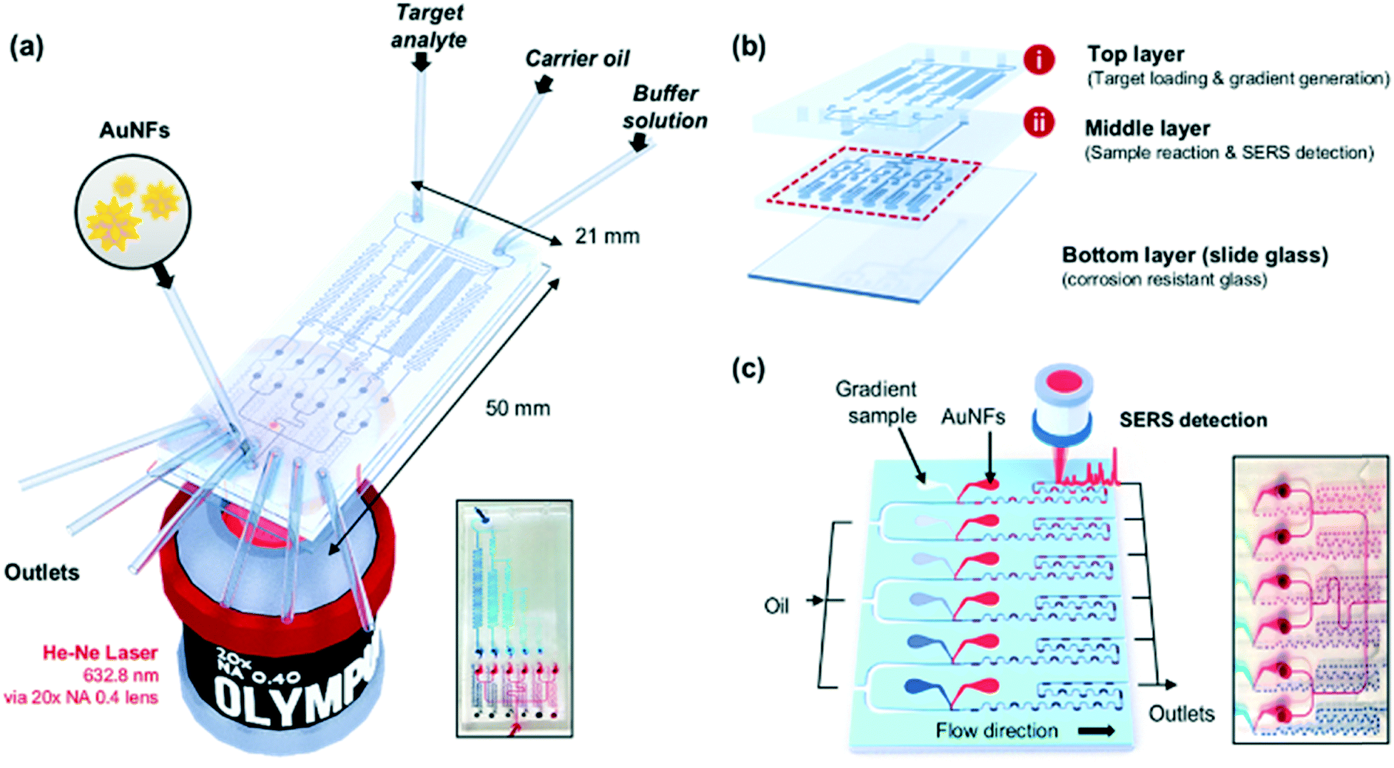 | ||
| Fig. 1 (a) Schematic design of a gradient droplet microfluidic chip for SERS-based high throughput gradient analysis. Gold nanoflowers (AuNFs), target analyte to be diluted, buffer solution, and carrier oil were injected into the channel inlets, and the SERS signals were measured using a He–Ne laser for multiple droplets containing various concentrations of a target reagent. (b) The system consists of two parallel layers: (i) target loading and serial dilution occur in the top panel, (ii) nanoparticle distribution, droplet generation, and SERS detection occur in the middle panel. (c) Image (left) and photo (right) of the middle layer showing the droplet generation and SERS detection. | ||
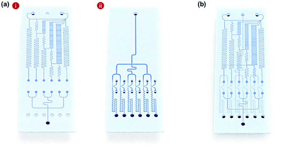 | ||
| Fig. 2 (a) Layouts of gradient droplet microfluidic channels consisting of two parallel layers: (i) Top layer: a reagent was serially diluted by buffer solution to make six different concentrations in the upper section, and gold nanoflowers (AuNFs) were equally distributed to six channels in the lower section. (ii) Middle layer: six different concentrations of a reagent and AuNFs were produced, and carrier oil was injected to generate six individual droplets. (b) Image of integrated double-layer micro-network gradient droplet channel. | ||
We previously reported a microfluidic gradient chip using serial dilution channels to generate six different concentrations of a reagent.19,20 A target reagent to be diluted and dilution buffer (i.e., deionized water) were simultaneously injected into the gradient generating panel (Fig. 3a). The dilution buffer and reagent were divided into five sub-channels (Ra) and two sub-channels (Rb and Rc), respectively. The reagent in one of the two divided channels passed through a channel (Rb), and the reagent in the other channel (Rc) mixed with dilution buffer in the merged channel (Rd). The diluted reagent sequentially repeated division and dilution steps. Finally, six different concentrations of a reagent were generated through four cascade-dilution steps (i = 4) and mixed with AuNFs at each junction of the distribution panel of the microfluidic device. To design the serial dilution channels for on-demand generation of six different concentrations of a reagent, we used an electro-hydraulic analogy (Kirchhoff's law),34 which defines a proper flow rate (Q) as electric current, pressure (P) as electric voltage, and flow resistance (R) in the microfluidic network.
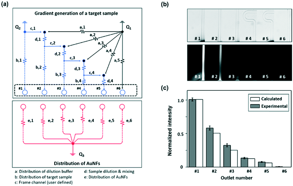 | ||
| Fig. 3 (a) Theoretical control module of gradient generation in the top layer using an electro-hydraulic analogy for serial dilution of a reagent. (b) Fluorescence image obtained at the end of the gradient generation section, using fluorescein dye and deionized water in the top layer. (c) The fluorescence intensity was calculated from the cross-section of each channel, demonstrating two-fold serial dilution of a reagent. | ||
From Kirchhoff's current law, the following conditions of a flow rate are satisfied:
| Qc,N + Qa,N = Qb,N+1 + Qc,N+1, where Qc,5 = 0 1 ≤ N ≤ i, where i = 4 | (1) |
The concentration of the sample in the Nth channel (CN) will be a function of two mixing flow rates:
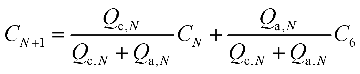 | (2) |
Solving eqn (1) and (2), the ratio of mixing flow rates can be defined as a function of the desired concentration profiles.
| Qc,N:Qa,N = (CN+1 − C6):(CN − CN+1), 1 ≤ N ≤ i, where i = 4 | (3) |
Using eqn (3), we designed a two-fold serial dilution mechanism, which determines a set of concentration values (C1:C2:C3:C4:C5:C6 = 100:50:25:12.5:6.25:0) and the ratio of flow rate (Qa,N:Qc,N = 1:1).
The flow resistances of each channel could be determined using Kirchhoff's voltage law:
 | (4) |
To simplify the circuit design, it was assumed that R was proportional to channel length, and the following parameters could be fixed.
| Rd,N = Rd Rc,N = Rc Ra,1 = iRc, where i = 4 | (5) |
Finally, the initial flow rates (Q1 and Q2) and all the channel lengths (Lb,1, Lb,2, Lb,3, Lb,4, La,1, La,2, La,3, La,4, La,5, Lc and Ld) could be determined using eqn (3)–(5), as shown in Table 1. A fluorescence microscope was used to access the performance of the gradient panel (Fig. 3b and c). As expected, the first gradient layer automatically generated different gradients with a two-fold dilution. To identify this gradient dilution, 1.0 mM fluorescein sodium salt solution and deionized water were injected into the channel to visualize the generation of different concentrations of a reagent in the microfluidic channel. For quantitative analysis of each serially diluted reagent, the fluorescence intensity was determined from the cross-section of each channel. Two-fold serial dilutions of a reagent were successfully generated, as shown by the normalized fluorescence intensity values in Fig. 3b. In the comparison between calculated and experimental fluorescence intensity values, however, the experimental intensity was slightly stronger than the calculated one from the second serial dilution. It was suspected that the difference was caused by a slightly different laminar flow formation between water and the fluorescence solution.
| Parameter | {Qb,1, …, Qb,6} (μL min−1) | Q 1 (μL min−1) | Q 2 (μL min−1) | L c (mm) | L d (mm) | L b,1 (mm) | L b,2 (mm) | L b,3 (mm) | L b,4 (mm) | L a,1 (mm) | L a,2 (mm) | L a,3 (mm) | L a,4 (mm) | L a,5 (mm) |
|---|---|---|---|---|---|---|---|---|---|---|---|---|---|---|
| Calculated value | 0.500 = (Q1 + Q2)/6 | 2.031 | 0.969 | 3.000 | 5.000 | 6.500 | 16.250 | 27.625 | 39.813 | 12.000 | 26.571 | 45.667 | 86.500 | 48.250 |
3.2 Design of fluidic channels for high-throughput droplet generation
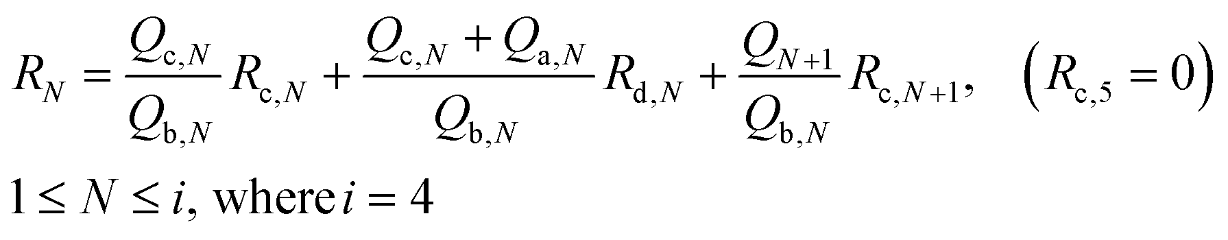
Six different concentrations of a reagent were distributed at the top layer and were conveyed to the droplet generation panels in the middle layer of the chip. At the junction between the top and middle layers of the chip, AuNFs were loaded into each parallel channel and then mixed with different concentrations of a sample. Here, the flow rate of AuNFs was kept the same as the rate of gradient samples.| Qb,N = Qe,N = 0.5 (μL min−1) where 1 ≤ N ≤ 6 | (6) |
Consequently, different concentrations of a reagent were efficiently mixed with AuNFs by passing through the winding channels. For generation of droplets, a mixture of chemically inert oil and surfactant was injected directly into the channel from the upper side. The optimum flow rate of continuous oil to generate a uniform droplet at each channel was determined to be 6 μL min−1. To generate a uniform flow rate at each channel, the flow resistances were set to the same value (Rf,1 = Rf,2 = Rf,3 = Rf,4 = Rf,5 = Rf,6), as shown in Fig. 4a.
 | ||
| Fig. 4 (a) Design of six individual droplet generation channels in the middle layer. (b) Photographic images of six channels demonstrating the mixing process between a reagent (blue ink) and gold nanoflowers (AuNFs, red ink) in the microfluidic channel. (c) The total droplet volume passing through each channel was calculated from the size of each droplet and the droplet frequency, demonstrating reliable droplet formation at each channel. | ||
Droplet generation at each parallel channel was recorded using a high-speed camera (PCO AG, Kelheim, Germany) to observe the number of droplets passing through a designated point. The colour changes of blue and red inks in Fig. 4b demonstrate formation of consistent droplets with different concentrations in the six channels. Fig. 4c shows that each gradient droplet in the six different channels maintained a consistent volume with a standard deviation of 0.044. The error bar indicates the standard deviation for the volumes of six microdroplets at each channel. To assess the reliability of droplet generation, the total volume of the droplets passing through each channel per minute was calculated and compared, as in Fig. S1.† Herein, the average droplet volume and the average number of droplets were estimated to be 5.75 nL and 167, respectively. SERS signals for this number of droplets were measured and compared for different concentrations of a reagent at each channel. Video S1† shows real-time tracking of the gradient droplet generation for six different concentrations of a reagent. This two-phase oil/aqueous solution regime enables minimization of resident time of a reagent in the encapsulated droplets. Consequently, the sample stacking problem caused by deposition of nanoparticle aggregates on channel surfaces was solved.
3.3 Quantitative analysis of MG using AuNFs in a microdroplet channel
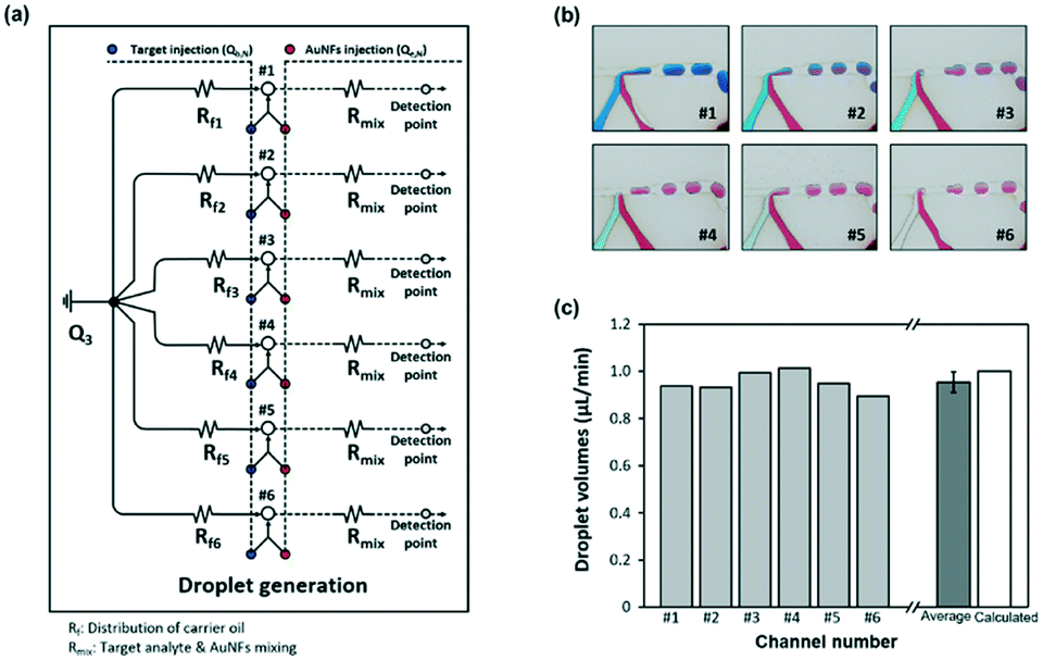
Gold nanoparticles are the most widely used enhancing probes in SERS detection. To gain a strong signal enhancement, aggregation of nanoparticles is needed because only molecules located at hot junctions can contribute to signal enhancement. In previous work, however, there existed a problem with reproducibility because particle aggregation is a random process and is difficult to control. Therefore, AuNFs were used for reproducible detection of MG in this work. Field enhancements can be achieved from the tips of an individual AuNF, and more reproducible SERS signals are achieved because aggregation is not required. Fig. S2† shows the TEM images of AuNFs for different amounts of gold nanosphere seeds in the 15–300 μL range. With the increase of gold nanosphere concentration, the solution colour changed from light blue to purple (Fig. S2a†). The corresponding UV/vis spectra in Fig. S2b† show that formation of branched structures gave rise to a red shift, indicating a change of the surface plasmon resonance property. Fig. S2c† shows TEM images monitoring AuNF evolution along the seed-mediated growth.To compare the sensitivity and reproducibility of AuNFs with those of AuNSs, the SERS spectra of MG in microdroplets were measured and analysed. First, 60 nm-diameter AuNSs and AuNFs were synthesized, and their size distributions were identified on TEM images, as shown in Fig. 5a. Their UV/vis spectral data showed that the surface plasmon band was shifted from 555 to 615 nm when AuNFs were formed through the growth of tips. Fig. 5c compares the SERS detection results of MG using AuNFs with those measured using AuNSs. In this SERS detection, the peak intensity at 1615 cm−1 was used for quantitative evaluation of MG. As shown in this figure, Raman intensity variations for AuNFs showed good agreement with those measured using AuNSs for various concentrations of MG. However, the average standard deviations calculated from the error bars revealed that AuNFs (5.84%) were more reproducible than AuNSs (32.6%) in the 0.20–50 μM range of MG. In Fig. S3,† the color of AuNSs–MG mixtures changes from red to gray when the concentration of MG is over 6.25 μM. This means the particles start to aggregate from this concentration. On the other hand, the color change of AuNFs–MG mixtures demonstrates that AuNFs start to aggregate when the concentration of MG reaches 50 μM. Corresponding UV-vis spectra show the same trends along the MG concentration change. Consequently, error deviations of AuNSs and AuNFs start to greatly increase from corresponding concentrations, 6.25 μM and 50 μM, respectively. In addition, the SERS detection results using AuNFs were more consistent in the low concentration range (0.20–1.56 μM) than those measured using AuNSs, as shown in the inset of Fig. 5c. This indicated that more sensitive quantitative analysis of MG was possible using AuNFs in the microdroplet channel. The limits of detection calculated from the standard deviations of five measurements were estimated to be 2.56 μM and 0.24 μM for AuNSs and AuNFs, respectively. Consequently, it can be concluded that more reproducible and sensitive SERS-based microdroplet detection of MG is possible using AuNFs.
 | ||
| Fig. 5 Comparison of chemical properties between gold nanospheres (AuNSs) and gold nanoflowers (AuNFs). (a) TEM images showing the size and morphology of AuNSs and AuNFs. They show similar size distribution. (b) UV absorbance spectra of AuNSs and AuNFs. The surface plasmon band of AuNFs demonstrates a red shift from the band of AuNSs. (c) Comparison of relative Raman intensities of malachite green (MG) for AuNSs and AuNFs. AuNFs shows stronger Raman intensity than AuNSs for MG in the low concentration region. | ||
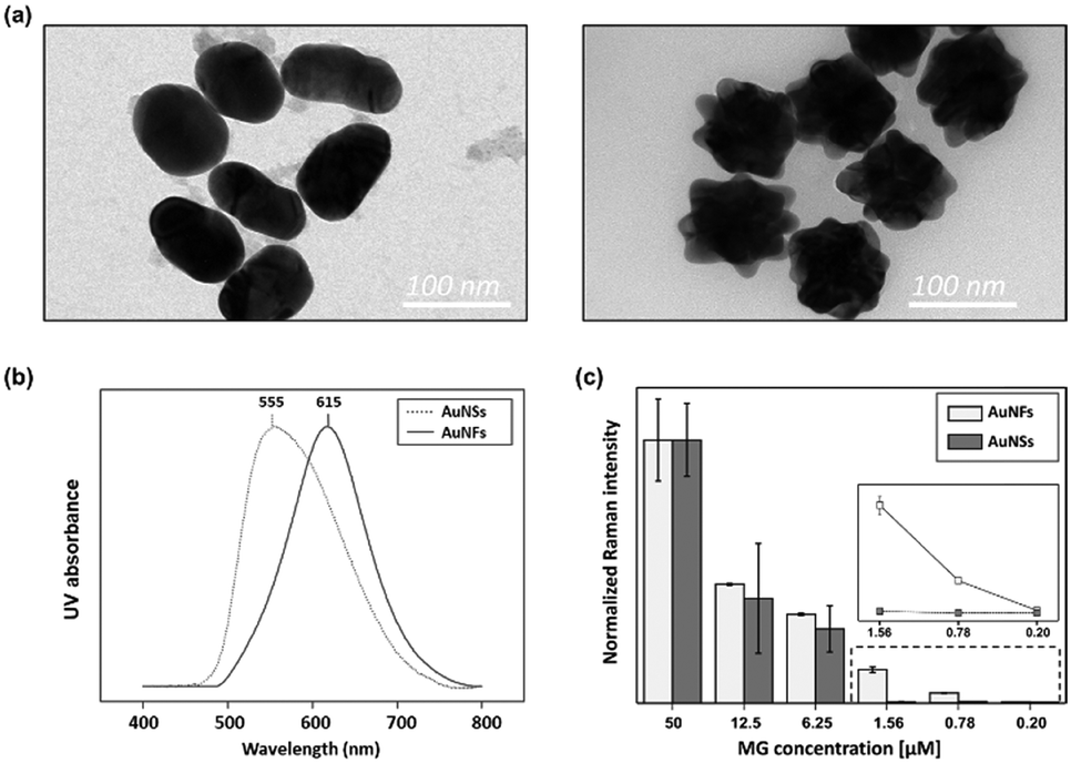
Fig. 6a shows the SERS spectra of MG collected from 6 gradient channels, and the photograph on the right side shows the corresponding gradient microdroplet channels filled with two different colours of ink. Herein, 100 μM of MG was serially diluted to six different concentrations using the gradient channels, and then different concentrations of MG were encapsulated in the oil phase and mixed with AuNFs inside each droplet. Finally, the Raman signal for each droplet channel was measured by focusing the laser beam on the centre of the channel after droplets passed through the winding channels. Spectral signals were collected for 10 s for each channel. Because the droplet generation rate was 167 droplets per min, the collected signals corresponded to the Raman signal for 28 droplets. As reported earlier, Raman spectra measured from a sequence of droplets include signals from carrier oil and aqueous droplets, but the SERS signals originating from the AuNFs inside the aqueous droplets were much stronger than those measured from the continuous oil phase. Fig. S4† shows the Raman spectra (400–1800 cm−1) of PDMS, liquid oil, MG and AuNFs mixtures and the same mixtures in the microdroplet channel, respectively. A weak Raman peak was observed at 747 cm−1 from liquid oil (red color). Three weak Raman peaks at 485 cm−1, 612 cm−1 and 680 cm−1 were observed from PDMS substrates. However, any Raman signals were not observed around 1615 cm−1, which was used for the quantitative evaluation of MG, from oil or PDMS substrates. Furthermore, the Raman intensities of PDMS and oil are negligible compared to the SERS signal intensity of MG adsorbed AuNFs. Therefore, we conclude that there is no interference from PDMS substrates and the oil. The Raman peak at 1615 cm−1 was used for quantitative evaluation of MG as shown in Fig. 6a. Fig. 6b shows the corresponding calibration curve of MG in the 0–100 μM range, indicating an excellent linear relationship (R2 = 0.995).
 | ||
| Fig. 6 Quantitative analysis of malachite green (MG) was performed in a SERS-based gradient droplet microfluidic system. (a) SERS spectra of different concentrations of MG were collected for 10 s at the end of each droplet generation channel. (b) Corresponding calibration plot of the Raman intensity in the linear range as a function of concentration of MG (correlation coefficient R2 = 0.995). The error bars indicate the standard deviations from three measurements for each concentration. | ||
4. Conclusions
In the present study, we designed and fabricated a conceptually new SERS-based droplet gradient chip for high throughput detection of various concentrations of a reagent. This chip was composed of two PDMS layers: one was a panel for serial dilution of a reagent using continuous, single-phase gradient channels, and the other was a panel for distribution of AuNFs and droplet generation. After accurate concentration gradients of a reagent were generated in the first layer, they were trapped into tiny droplets by oil injection in the second layer. This two-phase liquid/liquid segmented flow regime allowed minimization of resident time of a reagent through localization of reagents in the encapsulated droplets, and the sample stacking problem in the single flow regime was successfully resolved.In addition, SERS-based on-chip detection using AuNFs was performed for high throughput analysis of different concentrations of a reagent trapped in a series of droplets. When branched AuNFs are exposed to a laser beam, the incident field is greatly enhanced at the active sites, called electromagnetic hot junctions, by localized surface plasmon effects. Consequently, SERS is a highly sensitive on-chip detection method, with microdroplet platforms providing many advantages over microscale methods, including high analytical throughput, facile automation, and reduced sample requirements. Accordingly, the integration of SERS with microdroplet platforms offers significant utility in chemical and biological experimentation. Herein, we report a fully integrated SERS-based microdroplet platform for simultaneous detection of various concentrations of a reagent. These novel, SERS-based gradient microdroplet platforms are expected to be powerful analytical tools for high throughput detection of a chemical or biological reagent.
Conflicts of interest
There are no conflicts to declare.Acknowledgements
The National Research Foundation of Korea supported this work (grant numbers 2017M3D1A1039287 and 2018M3A7B4071203). The National Natural Science Foundation of China partially supported this work (grant numbers 41776110 and 21575159).References
- A. Jain, A. Graveline, A. Waterhouse, A. Vernet, R. Flaumenhaft and D. E. Ingber, Nat. Commun., 2016, 7, 10176 CrossRef CAS PubMed.
- K. Kwapiszewska, A. Michalczuk, M. Rybka, R. Kwapiszewski and Z. Brzózka, Lab Chip, 2014, 14, 2096–2104 RSC.
- T. G. G. Alicia, C. Yang, Z. Wang and N.-T. Nguyen, Lab Chip, 2016, 16, 368–376 RSC.
- H. Chon, C. Lim, S.-M. Ha, Y. Ahn, E. K. Lee, S.-I. Chang, G. H. Seong and J. Choo, Anal. Chem., 2010, 82, 5290–5295 CrossRef CAS PubMed.
- Y. Zeng, J.-Q. Ren, A.-G. Shen and J.-M. Hu, J. Am. Chem. Soc., 2018, 140, 10649–10652 CrossRef CAS PubMed.
- C. Zong, M. Xu, L.-J. Xu, T. Wei, X. Ma, X.-S. Zheng, R. Hu and B. Ren, Chem. Rev., 2018, 118, 4946–4980 CrossRef CAS PubMed.
- G. C. Phan-Quang, E. H. Z. Wee, F. Yang, H. K. Lee, I. Y. Phang, X. Feng, R. A. Alvarez-Puebla and X. Y. Ling, Angew. Chem., Int. Ed., 2017, 56, 5565–5569 CrossRef CAS PubMed.
- B. Tang, J. Wang, J. A. Hutchison, L. Ma, N. Zhang, H. Guo, Z. Hu, M. Li and Y. Zhao, ACS Nano, 2016, 10, 871–879 CrossRef CAS PubMed.
- T. Gong, Z.-Y. Hong, C.-H. Chen, C.-Y. Tsai, L.-D. Liao and K. V. Kong, ACS Nano, 2017, 11, 3365–3375 CrossRef CAS PubMed.
- Z. Cheng, N. Choi, R. Wang, S. Lee, K. C. Moon, S.-Y. Yoon, L. Chen and J. Choo, ACS Nano, 2017, 11, 4926–4933 CrossRef CAS PubMed.
- Z. Wang, S. Zong, L. Wu, D. Zhu and Y. Cui, Chem. Rev., 2017, 117, 7910–7963 CrossRef CAS PubMed.
- I. J. Jahn, O. Žukovskaja, X.-S. Zheng, K. Weber, T. W. Bocklitz, D. Cialla-May and J. Popp, Analyst, 2017, 142, 1022–1047 RSC.
- H. Pu, W. Xiao and D.-W. Sun, Trends Food Sci. Technol., 2017, 70, 114–126 CrossRef CAS.
- S. Bai, D. Serien, A. Hu and K. Sugioka, Adv. Funct. Mater., 2018, 28, 1706262 CrossRef.
- W. Yan, L. Yang, J. Chen, Y. Wu, P. Wang and Z. Li, Adv. Mater., 2017, 29, 1702893 CrossRef PubMed.
- Z. Wang, S. Zong, L. Wu, D. Zhu and Y. Cui, Chem. Rev., 2017, 117, 7910–7963 CrossRef CAS PubMed.
- W. Xie, R. Grzeschik and S. Schlücker, Angew. Chem., Int. Ed., 2016, 55, 13729–13733 CrossRef CAS PubMed.
- Y. Wang, R. Vaidyanathan, M. J. A. Shiddiky and M. Trau, ACS Nano, 2015, 9, 6354–6362 CrossRef CAS PubMed.
- N. Choi, K. Lee, D. W. Lim, E. K. Lee, S.-I. Chang, K. W. Oh and J. Choo, Lab Chip, 2012, 12, 5160–5167 RSC.
- M. Lee, K. Lee, K. H. Kim, K. W. Oh and J. Choo, Lab Chip, 2012, 12, 3720–3727 RSC.
- R. Gao, Z. Cheng, X. Wang, L. Yu, Z. Guo, G. Zhao and J. Choo, Biosens. Bioelectron., 2018, 119, 126–133 CrossRef CAS PubMed.
- S. Lin, W. Zhu, Y. Jin and K. B. Crozier, Nano Lett., 2013, 13, 559–563 CrossRef CAS PubMed.
- R. Gao, J. Ko, K. Cha, J. Ho Jeon, G.-e. Rhie, J. Choi, A. J. deMello and J. Choo, Biosens. Bioelectron., 2015, 72, 230–236 CrossRef CAS PubMed.
- S. Yadavali, H.-H. Jeong, D. Lee and D. Issadore, Nat. Commun., 2018, 9, 1222 CrossRef PubMed.
- R. Gao, Z. Cheng, A. J. deMello and J. Choo, Lab Chip, 2016, 16, 1022–1029 RSC.
- L. Wu, Z. Wang, S. Zong and Y. Cui, Biosens. Bioelectron., 2014, 62, 13–18 CrossRef CAS PubMed.
- J. Wang, M. Jin, Y. Gong, H. Li, S. Wu, Z. Zhang, G. Zhou, L. Shui, J. C. T. Eijkel and A. van den Berg, Lab Chip, 2017, 17, 1970–1979 RSC.
- N. Visaveliya, S. Lenke and J. M. Köhler, ACS Appl. Mater. Interfaces, 2015, 7, 10742–10754 CrossRef CAS PubMed.
- V. M. Kariuki, J. C. Hoffmeier, I. Yazgan and O. A. Sadik, Nanoscale, 2017, 9, 8330–8340 RSC.
- F. Lou, A. Wang, J. Jin, Q. Li and S. Zhang, Electrochim. Acta, 2018, 278, 255–262 CrossRef CAS.
- J. Huang, M. Guo, H. Ke, C. Zong, B. Ren, G. Liu, H. Shen, Y. Ma, X. Wang, H. Zhang, Z. Deng, H. Chen and Z. Zhang, Adv. Mater., 2015, 27, 5049–5056 CrossRef CAS PubMed.
- S. Li, L. Zhang, T. Wang, L. Li, C. Wang and Z. Su, Chem. Commun., 2015, 51, 14338–14341 RSC.
- J. Li, J. Wu, X. Zhang, Y. Liu, D. Zhou, H. Sun, H. Zhang and B. Yang, J. Phys. Chem. C, 2011, 115, 3630–3637 CrossRef CAS.
- K. Lee, C. Kim, B. Ahn, R. Panchapakesan, A. R. Full, L. Nordee, J. Y. Kang and K. W. Oh, Lab Chip, 2009, 9, 709–717 RSC.
Footnote |
| † Electronic supplementary information (ESI) available. See DOI: 10.1039/c8lc01180j |
| This journal is © The Royal Society of Chemistry 2019 |