
 Open Access Article
 This Open Access Article is licensed under a
 Creative Commons Attribution 3.0 Unported Licence
Characterization of silver-polymer core–shell nanoparticles using electron microscopy†
Nathalie
Claes
 a,
Ramesh
Asapu
b,
Natan
Blommaerts
b,
Sammy W.
Verbruggen
b,
Silvia
Lenaerts
b and
Sara
Bals
*a
a,
Ramesh
Asapu
b,
Natan
Blommaerts
b,
Sammy W.
Verbruggen
b,
Silvia
Lenaerts
b and
Sara
Bals
*a
aElectron Microscopy for Materials Science (EMAT), Department Physics, University of Antwerp, Groenenborgerlaan 171, B-2020 Antwerp, Belgium. E-mail: sara.bals@uantwerpen.be
bSustainable Energy, Air and Water Technology (DuEL), Department of Bioscience Engineering, University of Antwerp, Groenenborgerlaan 171, B-2020 Antwerp, Belgium
First published on 16th April 2018
Abstract
Silver-polymer core–shell nanoparticles show interesting optical properties, making them widely applicable in the field of plasmonics. The uniformity, thickness and homogeneity of the polymer shell will affect the properties of the system which makes a thorough structural characterization of these core–shell silver-polymer nanoparticles of great importance. However, visualizing the shell and the particle simultaneously is far from straightforward due to the sensitivity of the polymer shell towards the electron beam. In this study, we use different 2D and 3D electron microscopy techniques to investigate different structural aspects of the polymer coating.
Introduction
Metallic nanoparticles displaying surface plasmon resonance (SPR) have recently been used to induce or enhance visible light activity in photocatalysis.1,2 SPR is a unique optical property of metallic nanoparticles that originates from the collective oscillation of the conduction band electrons.3 The highest activities for plasmonic photocatalysts are obtained when the wavelength of the incident light matches the SPR wavelength. Therefore, tuning the SPR maximum to the visible region is highly promising in order to use plasmonic photocatalysis as a sustainable technology. Different properties such as the type of metal, the surrounding dielectric environment, and the particle size and shape have an influence on the SPR wavelength.1 Silver and gold nanoparticles are often used since they show pronounced SPR in the visible range of the spectrum. Silver nanoparticles are of specific interest since they produce a sharper and stronger plasmonic resonance than gold. Also, the plasmonic resonance of silver nanoparticles appears at higher energies/shorter wavelengths in comparison with gold, which provides a broader range of tunability of the plasmonic resonance frequency.4 The enhanced near-field can boost the excitation of electron–hole pairs in TiO2, which is a high-performance photocatalytic material, and Ag@TiO2 systems are therefore expected to yield a higher catalytic activity. However, some experimental results have shown an opposite behavior.5 Apart from island formation on the surface, a possible explanation can be found in the chemical properties of silver nanoparticles. Silver nanoparticles are indeed chemically very reactive and it is expected that they readily oxidize in contact with air.6 In order to prevent oxidation, silver nanoparticles can be encapsulated with a passive material such as SiO2 or a polymer.6–10 It is hereby important that the protection layer is sufficiently thin since it is expected that the amplitude of the electric near-field decays exponentially with the distance from the nanoparticle's surface.11 Silver encapsulation can be performed by using organic linkers and capping ligands.7,12,13 The main drawback of these methods is that they do not allow control over the shell thickness. Minor changes in the shell thickness can modify the near field enhancement to a large extent. Therefore, a layer by layer (LbL) method was recently proposed.7,14,15 Hereby, the metallic silver core is encapsulated with an ultra-thin protective shell by sequential cycles of adsorption and washing of the alternatively charged polyelectrolytes poly(allylamine hydrochloride) (PAH) and polyacrylic acid (PAA). Since the polymer shell is built layer by layer, it is expected that the shell thickness can be accurately controlled.In this study, we investigate the thickness and uniformity of the polymer shell for silver nanoparticles encapsulated by a different number of LbL cycles using electron microscopy. This technique has the advantage that it provides more local information in comparison with e.g. XPS.16 One of the main challenges is the sensitivity of the polymer shell towards the electron beam.17 In addition, it is far from straightforward to visualize the shell and the particle simultaneously. Therefore, bright field electron microscopy tilt series were used as an input for 3D reconstruction techniques. Also the organization of the polymer molecules at the particle–shell interface is investigated. Finally, the influence of the thickness of the polymer layer on the plasmonic properties of silver nanoparticles is examined by electron energy loss spectroscopy (EELS).
Results and discussion
Thickness of the polymer shell
Studying the thickness and uniformity of the polymer shell surrounding a silver core is far from straightforward due to the lack of contrast and the sensitivity of the polymer when being investigated by TEM. Fig. 1a shows an Ag nanoparticle encapsulated by 4 layers of polymer deposited on a commercial carbon coated Cu TEM grid. It is clear that only contrast related to the Ag particle can be observed. Previously, polymer shells in inorganic-polymer core–shell nanoparticles could be visualized through staining by ruthenium tetroxide18 or through selective absorption of chemical molecules.19 However, such a chemical treatment might influence the polymer structure and hamper a quantitative measurement of the thickness.20 Cryo-TEM has also been shown to be a suitable technique to visualize nanoparticles encapsulated in polymeric templates.21 Unfortunately, cryo-TEM images typically show a very low signal to noise ratio, which will hamper a quantitative interpretation when the polymeric structure is very thin, such as for the Ag-polymer core–shell nanoparticles in this study. Herein, Ag encapsulated polymer nanoparticles were therefore deposited on an ultrathin (∼3 nm) holey carbon layer (see the Experimental section). In this way, the polymer shell could be visualized as illustrated in Fig. 1b.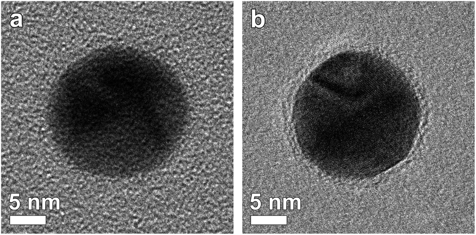 | ||
| Fig. 1 Silver nanoparticles encapsulated by 4 layers of polymer deposited on (a) a commercial Cu TEM grid and (b) an ultrathin carbon film coated TEM grid. Only when using an ultrathin support, the polymer shell can be visualized. | ||
Next, different systems were considered. Fig. 2 shows four-, six-, eight- and twelve-layered Ag-polymer core–shell nanoparticles, denoted as Ag-L4, Ag-L6, Ag-L8 and Ag-L12, respectively.
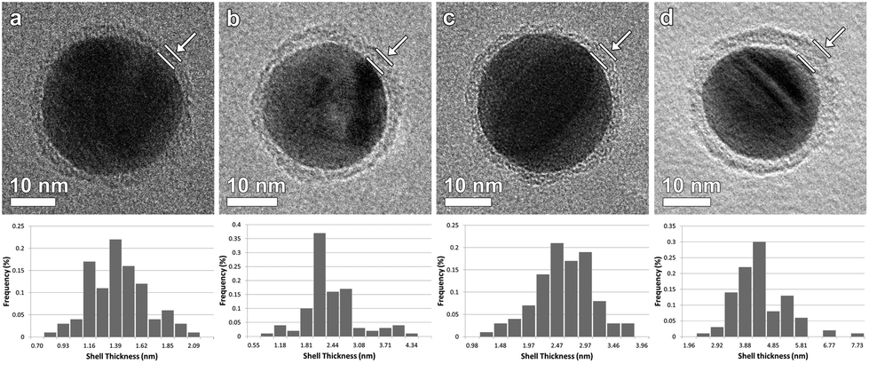 | ||
| Fig. 2 BF-TEM images of (a) Ag-L4, (b) Ag-L6, (c) Ag-L8 and (d) Ag-L12 and corresponding distribution of the shell thicknesses. | ||
Based on BF-TEM images, the shell thickness could be determined to be (1.36 ± 0.03) nm for Ag-L4, (2.23 ± 0.07) nm for Ag-L6, (2.47 ± 0.05) nm for Ag-L8 and (4.17 ± 0.09) nm for Ag-L12 as derived from 100 thickness measurements. Fig. 2 also shows the distribution of the shell thickness for Ag-L4, Ag-L6, Ag-L8 and Ag-L12. The increasing shell thickness proves the continuous growth of the shell with increasing number of polyelectrolyte layers.14 The relatively large standard deviation of the shell thicknesses can be understood by the molecular arrangement of the polymer, which is discussed later in the text.
Homogeneity of the polymer shell
So far, thickness measurements for these silver-polymer core–shell nanoparticles have been performed based on two dimensional images.14 However, one should never neglect that 2D TEM images of an unknown 3D object can be very misleading. To investigate the uniformity of the polymer shell, electron tomography is therefore required.22 Hereby, 2D projections are acquired over a tilt range as large as possible. Next, the tilt series is aligned and used as an input for a 3D reconstruction. To obtain a reliable 3D reconstruction, the so-called “projection requirement” for tomography needs to be fulfilled. This requirement states that the intensity of the projections should show a monotonic relationship with some function of the thickness or density of the material.23 BF-TEM images of polymers are dominated by mass–thickness contrast, which fulfils this projection requirement but for metallic-polymer core–shell nanoparticles this is no longer the case. Indeed, diffraction contrast is the dominant mechanism in BF-TEM images of crystalline specimens. This explains why high angle annular dark field scanning transmission electron microscopy (HAADF-STEM) is typically used for electron tomography experiments in materials science.Unfortunately, we were not able to image the polymer shell by HAADF-STEM, because of the extreme sensitivity towards the focussed electron probe. Despite the violation of the projection requirement, we acquired the BF-TEM tilt series of the polymer coated Ag nanoparticles. Projection images were recorded over a tilt range of ±78° with a tilt increment of 2°. To keep the polymer shell stable during the acquisition, a reduced beam current was used (Fig. S1†). In almost each of the projections, severe diffraction contrast was observed. In Fig. 3, the 3D results for Ag-L4 and Ag-L8 are shown. The tomography results for Ag-L6 and Ag-L12 are presented in the ESI (Fig. S2†).
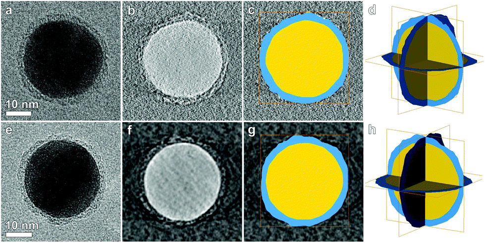 | ||
| Fig. 3 (a, e) BF-TEM projection at 0° for, respectively, Ag-L4 and Ag-L8. (b, f) Slices through the reconstructed 3D volumes obtained by weighted back projection and (c, g) superimposed segmentation. Figures (d, h) show the result of the 3D segmentation. The polymer shell (blue) encapsulates the complete particle (yellow). A 3D visualization is shown in the ESI.† | ||
In Fig. 3b and f, orthoslices through the 3D reconstructions obtained using weighted back projection (WBP) are presented. Although the WBP technique enabled the visualization of the polymer shell around the particle, a threshold based segmentation failed due to the poor contrast. Therefore, a slice by slice manual segmentation was performed. From this analysis, we could estimate that the thickness of the shell varies between 1.3 and 1.9 nm for Ag-L4 and between 2.5 and 3 nm for Ag-L8 which is within the range determined by 2D TEM imaging. Moreover, electron tomography reveals that the polymer shell entirely encapsulates the Ag nanoparticle and therefore proves that the shell thickness can be accurately controlled using the LbL-method.
The main added value of a thin conformal polymer shell is that it can prevent oxidation and agglomeration of the silver cores. In this respect, it is crucial to verify whether the silver nanoparticles are indeed completely encapsulated by the polymer shell. Holes in the coating could still lead to interaction with oxygen and would allow oxidation. 3D tomography in this work demonstrates that the LbL envelopment strategy is in fact successful, which is in line with the long-term stable photocatalytic activity of TiO2 modified with such core–shell nanoparticles as measured in earlier work.7 An additional benefit of synthesizing a homogeneous thin shell and the proposed methodology to very accurately determine its thickness is that in this way the spacing between two adjacent silver cores can be carefully tuned. This will in turn govern the resulting near-field enhancement in the hot-spot zone located in-between two particles. Recently, this strategy to tune and model the surface-enhanced Raman spectroscopy (SERS) signal enhancement for dye molecules located in such a wet-chemically controlled nanogap has been exploited.24
Molecular arrangement of the polymer shell
In order to investigate the organization of the polymer molecules at the interface with the particle, high resolution TEM (HRTEM) images were acquired (Fig. S3†). In general, a HRTEM image is not a simple projection but a complex interference pattern formed by the interaction of the electron beam with the specimen, which is further scrambled by the electron optical system of the microscope. As a consequence, the interpretation of HRTEM images is far from intuitive, especially for non periodic systems such as the interfaces in this study. We therefore used exit wave reconstruction, a technique based on the acquisition of a focal series of HRTEM images. By inverting the image formation process and hereby eliminating the lens aberrations, all information can be recovered up to the microscope's information limit.25–27 From the reconstructed exit wave, the phase image can be extracted, which makes direct interpretation of the atomic structure possible. Indeed, when the sample is sufficiently thin, the reconstructed phase image is proportional to the projection potential, and this means the projected atomic arrangement.28Fig. 4 shows the reconstructed phase images of an Ag-L8 particle. We conclude that very often the polymer molecules are oriented parallel to the surface of the particle as indicated by the white arrow in Fig. 4b. Sometimes the polymer chains don't attach linearly and the next chain is attached to a side chain. This means that only one end is attached and the other end can orient in different directions (blue arrow). The next layer of polymer is built on this rough surface. At the end, this might result in a deviation in shell thickness, which is observed before in the shell thickness determination for different amounts of layers.
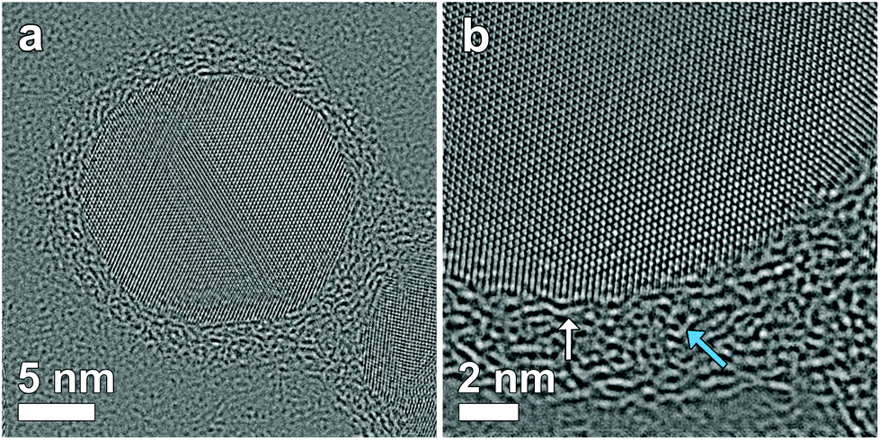 | ||
| Fig. 4 A focal series of 15 HRTEM images are used to perform exit wave reconstruction. Phase images of the reconstructed exit wave of different particles show clearly the presence and position of the polymer shell around the particles. The white arrow indicates the presence of parallel oriented polymer chains, while the blue arrow shows the presence of chains in different orientations. | ||
Plasmonic properties
The encapsulation of the silver nanoparticles by a polymer shell has been shown to be beneficial to reduce clustering and to prevent oxidation over a prolonged time period.7 The 3D tomography results from Fig. 3 confirm complete envelopment of the silver core by a protective polymer shell, which substantiates the ultra-stable properties of these core–shell nanostructures. However, the presence of the polymer shell may at the same time also influence the plasmonic modes of silver nanoparticles. Therefore, we performed low loss EELS in order to compare the plasmonic modes of bare silver, and four-, six-, eight- and twelve-layered core–shell nanoparticles. For all particles, EELS spectra were recorded at different locations, revealing the presence of multiple plasmonic resonances.The experimentally obtained EELS spectra were compared with the simulated spectra. The theoretical simulations of the EELS spectra were performed with a MNPBEM toolbox based on the boundary element method for metallic nanoparticles.29,30 Using this method, the boundaries between the different materials are discretized by using a geometrical mesh, and afterwards the Maxwell equations are solved using these boundary conditions. The dielectric function of Ag was calculated from optical data.31 For the polymers PAA/PAH the dielectric function was approximated by a constant since PAH/PAA polymers are non-absorbing in the near UV to visible region (300–800 nm) and the variation in dielectric data is here minimal. The dielectric constant ε was calculated based on the refractive index n = 1.48 as ε = n2.7,32 The influence of the carbon support was neglected during the simulations.
The efficiency of plasmonic field enhancement heavily depends on the overlap of the plasmonic resonance absorption band and the principal excitation wavelength of the incident light source.33 When both coincide, a maximal enhancement of the near field will be obtained. It is well known that increasing the nanostructure's size, i.e. by adding polymer layers with a higher refractive index than that of the surrounding aqueous medium, the principal SPR wavelength will experience a red-shift (Fig. 5). In order to guarantee an optimal overlap of the resulting SPR absorption band with the excitation wavelength, it is again very important to determine the exact thickness of the encapsulating layer, as this will in turn drive the red-shift of the plasmonic peak.
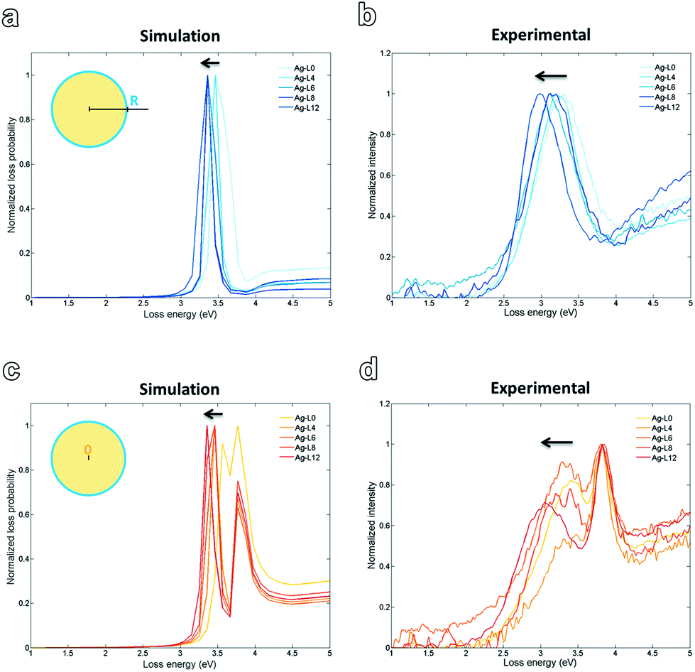 | ||
| Fig. 5 Simulated spectra with impact parameter R (a) and 0 (c). Experimentally obtained EELS spectra show a similar trend for both impact parameters (b, d). | ||
Fig. 5 shows the simulated and experimentally obtained spectra at positions 0 (centre of the Ag particle, bulk) and R, with R being the radius of the particle. The band broadening observed for the experimental spectra with respect to the simulations can be ascribed to the polydispersity of the colloidal Ag-LX (X = number of layers) solutions, whereas in the simulation perfectly monodisperse colloidal spheres are assumed. For both, at the surface and in the bulk the simulated peak shifts slightly towards lower energy/higher wavelength with increasing amount of polymer layers. Experimentally a similar trend is observed. This is consistent with the theory that the SPR peak experiences a slight red-shift due to an increase in the particle size upon progressive addition of polyelectrolyte layers. This red-shift is also confirmed experimentally by UV-vis spectroscopy,7 as well as theoretically by calculated extinction spectra based on Mie theory.24
Conclusions
For silver-polymer core–shell nanoparticles, the soft shell and the hard core were visualized simultaneously by BF-TEM. Tomography experiments showed the presence of a complete polymer layer around the particles. By exit wave reconstruction, it was found that a fraction of the polymer chains were connected in different orientations, which explains the spread in the polymer shell thickness. A small shift towards lower energy was observed in the low loss EELS spectra with increasing polymer shell thickness.Experimental
Silver encapsulated nanoparticles
Silver nanoparticles were synthesized by reduction of silver nitrate with tannic acid and trisodium citrate.34 In brief, a solution mixture of tannic acid (0.05 mM) and trisodium citrate (5 mM) was brought to boil under vigorous stirring in a round bottom flask. 1 mL of 25 mM silver nitrate solution was quickly injected and the boiling was continued for 30 minutes under a condenser setup. The solution was cooled to room temperature and centrifuged to separate the colloidal silver nanoparticles. Afterwards, the silver nanoparticles were redispersed in water. Next, the metallic silver cores are encapsulated with ultra-thin protective shells using the LbL technique. This approach is based on sequential cycles of adsorption and washing of the alternatively charged polyelectrolytes poly(allylamine hydrochloride)(PAH) and polyacrylic acid (PAA), as reported in earlier work.7,14 Silver colloidal nanoparticles (5 × 10¹³ NPs per mL concentration) were encapsulated using the polyelectrolyte bilayer combination of 5 g L−1 PAH and 10 g L−1 PAA solutions in such a way that an excess of polyelectrolyte chains is maintained at a ratio of 60![[thin space (1/6-em)]](https://www.rsc.org/images/entities/char_2009.gif) 000 chains per nanoparticle during the wet chemical synthesis.
000 chains per nanoparticle during the wet chemical synthesis.
Transmission electron microscopy (TEM)
Ag coated polymer nanoparticles are deposited on an ultrathin carbon layer on the top of a Cu TEM grid. Holey carbon coated Cu TEM grids are placed on filter paper in a glass Petri dish filled with ultra-pure water. An ultrathin 3 nm thick carbon layer, obtained using adaptive carbon thread evaporation,35 is lowered slowly into the water under an angle of 30°. Through capillary forces, the carbon layer is released from the substrate. The filter paper with TEM grids is slowly removed from the water assuring that the floating carbon layer is deposited on the grids. Finally, the grids are dried at 40 °C.Bright field TEM (BF-TEM) measurements were performed using a FEI Osiris microscope operated at 200 kV. For tomography, projections were acquired over a tilt range of ±78° with an increment of 2°. After the alignment, the series were reconstructed by using a mathematical algorithm, here the weighted back projection implemented in Inspect 3D (FEI).
High resolution TEM images were acquired using an aberration-corrected cubed FEI Titan 50–80 using a negative spherical aberration (Cs = −5 μm). Under these negative spherical aberration conditions, high contrast is observed.36 Focal series for exit wave reconstruction consist of 30 images acquired with a starting defocus of 30 nm and an equidistant focal decrease of 2 nm. Reconstruction of the exit wave and offline correction of residual aberrations was carried out using the TrueImage software.37
To map the plasmonic resonances, high angle annular dark field scanning transmission electron microscopy (HAADF-STEM) imaging is combined with monochromated STEM-EELS in the low loss regime. All experiments were performed using an aberration-corrected cubed FEI Titan 50–80 operated at 120 kV. The monochromated electron probe yields a full width half maximum of the zero-loss peak of 0.15–0.17 eV. Theoretical simulations of the EELS spectra were performed for metallic nanoparticles using the boundary element method MNPBEM.29,30
Conflicts of interest
There are no conflicts to declare.Acknowledgements
N. C. and S. B. acknowledge financial support from European Research Council (ERC Starting Grant #335078-COLOURATOMS) and from the FWO through project funding (G038116N). R. A. and S. L. acknowledge the Research Foundation Flanders (FWO) for financial support.Notes and references
- S. W. Verbruggen, J. Photochem. Photobiol., C, 2015, 24, 64–82 CrossRef CAS.
- X. Zhang, Y. L. Chen, R.-S. Liu and D. P. Tsai, Rep. Prog. Phys., 2013, 76, 46401 CrossRef PubMed.
- S. a. Maier, Fundamentals and Applications Plasmonics: Fundamentals and Applications, 2004, vol. 677 Search PubMed.
- K. T. Yong, Y. Sahoo, M. T. Swihart and P. N. Prasad, Colloids Surf., A, 2006, 290, 89–105 CrossRef CAS.
- T. Hirakawa and P. V. Kamat, J. Am. Chem. Soc., 2005, 127, 3928–3934 CrossRef CAS PubMed.
- K. Awazu, M. Fujimaki, C. Rockstuhl, J. Tominaga, H. Murakami, Y. Ohki, N. Yoshida and T. Watanabe, J. Am. Chem. Soc., 2008, 130, 1676–1680 CrossRef CAS PubMed.
- R. Asapu, N. Claes, S. Bals, S. Denys, C. Detavernier, S. Lenaerts and S. W. Verbruggen, Appl. Catal., B, 2017, 200, 31–38 CrossRef CAS.
- H. S. Toh, K. Jurkschat and R. G. Compton, Chem. – Eur. J., 2015, 21, 2998–3004 CrossRef CAS PubMed.
- V. K. Sharma, K. M. Siskova, R. Zboril and J. L. Gardea-Torresdey, Adv. Colloid Interface Sci., 2014, 204, 15–34 CrossRef CAS PubMed.
- K. N'Konou, M. Chalh, V. Monnier, N. P. Blanchard, Y. Chevolot, B. Lucas, S. Vedraine and P. Torchio, Synth. Met., 2018, 239, 22–28 CrossRef.
- M. Kerker, J. Colloid Interface Sci., 1985, 105, 297–314 CrossRef CAS.
- F. Porcaro, L. Carlini, A. Ugolini, D. Visaggio, P. Visca, I. Fratoddi, I. Venditti, C. Meneghini, L. Simonelli, C. Marini, W. Olszewski, N. Ramanan, I. Luisetto and C. Battocchio, Materials, 2016, 9, 1–15 CrossRef PubMed.
- S. T. Kochuveedu, T. Son, Y. Lee, M. Lee, D. Kim and D. H. Kim, Sci. Rep., 2014, 4, 1–8 Search PubMed.
- G. Schneider and G. Decher, Nano Lett., 2004, 4, 1833–1839 CrossRef CAS.
- L. L. Del Mercato, A. Z. Abbasi, M. Ochs and W. J. Parak, ACS Nano, 2011, 5, 9668–9674 CrossRef CAS PubMed.
- C. Battocchio, C. Meneghini, I. Fratoddi, I. Venditti, M. V. Russo, G. Aquilanti, C. Maurizio, F. Bondino, R. Matassa, M. Rossi, S. Mobilio and G. Polzonetti, J. Phys. Chem. C, 2012, 116, 19571–19578 CAS.
- R. F. Egerton, P. Li and M. Malac, Micron, 2004, 35, 399–409 CrossRef CAS PubMed.
- X. Wang, N. You, F. Lan, P. Fu, Z. Cui, X. Pang, M. Liu and Q. Zhao, RSC Adv., 2017, 7, 7789–7792 RSC.
- A. M. Percebom, J. J. Giner-Casares, N. Claes, S. Bals, W. Loh and L. M. Liz-Marzán, Chem. Commun., 2016, 52, 4278–4281 RSC.
- L. Staniewicz, A. M. Donald and D. J. Stokes, J. Phys.: Conf. Ser., 2010, 241, 12077 CrossRef.
- Y. Mei, Y. Lu, F. Polzer, M. Ballauff and M. Drechsler, Chem. – Eur. J., 2007, 19, 1062–1069 CAS.
- P. A. Midgley and S. Bals, in Handbook of Nanoscopy, 2012, vol. 1 & 2, pp. 253–279 Search PubMed.
- J. M. Thomas, P. A. Midgley, T. J. V. Yates, J. S. Barnard, R. Raja, I. Arslan and M. Weyland, Angew. Chem., Int. Ed., 2004, 43, 6745–6747 CrossRef CAS PubMed.
- R. Asapu, R.-G. Ciocarlan, N. Claes, N. Blommaerts, M. M. Minjauw, T. Ahmad, J. Dendooven, P. Cool, S. Bals, S. Denys, C. Detavernier, S. Lenaerts and S. W. Verbruggen, ACS Appl. Mater. Interfaces, 2017, 9, 41577–41585 CAS.
- M. Op De Beeck and D. Van Dyck, Ultramicroscopy, 1996, 64, 153–165 CrossRef CAS.
- D. Lolla, J. Gorse, C. Kisielowski, J. Miao, P. L. Taylor, G. G. Chase and D. H. Reneker, Nanoscale, 2015, 8, 120–128 RSC.
- F.-R. Chen, C. Kisielowski and D. Van Dyck, Adv. Struct. Chem. Imaging, 2017, 3, 8 CrossRef PubMed.
- S. Bals, S. Van Aert, G. Van Tendeloo and D. Ávila-Brande, Phys. Rev. Lett., 2006, 96, 1–4 CrossRef PubMed.
- U. Hohenester and A. Trügler, Comput. Phys. Commun., 2012, 183, 370–381 CrossRef CAS.
- U. Hohenester, Comput. Phys. Commun., 2014, 185, 1177–1187 CrossRef CAS.
- P. B. Johnson and R. W. Christy, Phys. Rev. B: Solid State, 1972, 6, 4370–4379 CrossRef CAS.
- K. H. Kyung, K. Fujimoto and S. Shiratori, Jpn. J. Appl. Phys., 2011, 50, 35803 CrossRef.
- D. B. Ingram, P. Christopher, J. L. Bauer and S. Linic, ACS Catal., 2011, 1, 1441–1447 CrossRef CAS.
- V. Bastús, N. Merkoçi, F. Piella and J. Puntes, Chem. Mater., 2014, 26, 2836–2846 CrossRef.
- J. Leroux and F. de Weert, Application Note Ultra-Thin Carbon Films Ways to Reveal More form your Samples: Ultra-Thin Carbon Films, 2016 Search PubMed.
- K. W. Urban, C.-L. Jia, L. Houben, M. Lentzen, S.-B. Mi and K. Tillmann, Philos. Trans. R. Soc., A, 2009, 367, 3735–3753 CrossRef PubMed.
- C. Kübel and A. Thust, Program True Image: Focal-Series Reconstruction Package, FEI Company, 2003 Search PubMed.
Footnote |
| † Electronic supplementary information (ESI) available. See DOI: 10.1039/C7NR09517A |
| This journal is © The Royal Society of Chemistry 2018 |