
 Open Access Article
 This Open Access Article is licensed under a
 Creative Commons Attribution 3.0 Unported Licence
Dysprosium electrodeposition from a hexaalkylguanidinium-based ionic liquid†
Claudia A.
Berger
a,
Maria
Arkhipova
b,
Gerhard
Maas
b and
Timo
Jacob
*ac
aInstitute of Electrochemistry, Ulm University, Albert-Einstein-Allee 47, 89081 Ulm, Germany. E-mail: Timo.Jacob@uni-ulm.de
bInstitute of Organic Chemistry I, Ulm University, Ulm, Germany
cHelmholtz-Institute-Ulm (HIU), Ulm, Germany
First published on 11th April 2016
Abstract
The rare-earth element dysprosium (Dy) is an important additive that increases the magnetocrystalline anisotropy of neodymium magnets and additionally prevents from demagnetizing at high temperatures. Therefore, it is one of the most important elements for high-tech industries and is mainly used in permanent magnetic applications, for example in electric vehicles, industrial motors and direct-drive wind turbines. In an effort to develop a more efficient electrochemical technique for depositing Dy on Nd-magnets in contrast to commonly used costly physical vapor deposition, we investigated the electrochemical behavior of dysprosium(III) trifluoromethanesulfonate in a custom-made guanidinium-based room-temperature ionic liquid (RTIL). We first examined the electrodeposition of Dy on an Au(111) model electrode. The investigation was carried out by means of cyclic voltammetry (CV) and X-ray photoelectron spectroscopy (XPS). The initial stages of metal deposition were followed by in situ scanning tunneling microscopy (STM). CV measurements revealed a large cathodic reduction peak, which corresponds to the growth of monoatomic high islands, based on STM images taken during the initial stages of deposition. XPS identified these deposited islands as dysprosium. A similar reduction peak was also observed on an Nd–Fe–B substrate, and positively identified as deposited Dy using XPS. Finally, we varied the concentration of the Dy precursor, electrolyte flow and temperature during Dy deposition and demonstrated that each of these parameters could be used to increase the thickness of the Dy deposit, suggesting that these parameters could be tuned simultaneously in a temperature-controlled flow cell to enhance the thickness of the Dy layer.
1. Introduction
The rare-earth element dysprosium (Dy) is rather unique amongst the magnetic materials, exhibiting both the highest magnetic moment per atom (10μB) and the highest saturation magnetization of any element.1 Therefore, it is no surprise that in its most prominent industrial application it is alloyed into neodymium–iron–boron magnets2 in order to increase the magnetocrystalline anisotropy.3 Neodymium–iron–boron magnets were invented by Sagawa et al. in 1984![[thin space (1/6-em)]](https://www.rsc.org/images/entities/char_2009.gif) 4 and are now widely employed as magnetic field sources in hybrid electric vehicles and wind turbines,5 for instance. Indeed, as early as 2007, 30000 tons per year of neodymium magnets were being produced worldwide.6 Current industrial methods rely on a combination of physical vapor deposition (PVD)7 and sputtering techniques to produce Dy layers. The high energy cost of these methods, due to the high-vacuum conditions they require, makes them ecologically unsustainable, particularly at large scales. However, the electrochemical deposition of dysprosium from non-aqueous solvents has been put forward as a promising alternative to present industrial methods.8 Room-temperature ionic liquids (RTILs) are organic salts, which are in the molten state at room-temperature.9 Seemingly almost innumerable combinations of different anions and cations are possible, resulting in a vast variety of potential RTILs with tunable physicochemical properties that can be tailored for specific applications.10 Besides well-investigated ionic liquids (ILs) with common imidazolium, pyridinium or piperidinium cations, there are new classes of ILs which are still being developed. One example here are RTILs, which already contain lanthanides in their anions and cations.11–15 Another promising new class of ILs are hexaalkyl-substituted guanidinium salts, because of the flexibility that can be achieved by tuning each of the six alkyl groups independently.16 In addition, they exhibit good thermal stability and are unreactive toward bases and most nucleophilic reagents due to the excellent charge stabilization in the peralkylated cation. Applications in electrochemistry have driven recent interest in RTILs, making their large electrochemical windows and high ionic conductivities two of their most important features along with their low vapor pressures and high thermal stabilities.17–22 Indeed, the fact that RTILs enable access to the electrodeposition of non-noble metals, which cannot be deposited from aqueous solutions, more than compensates for their high viscosities and costs, when considering their usefulness in a wide range of applications. One of these non-noble metals is dysprosium, the electrodeposition of which several groups have demonstrated from commercially available ionic liquids, e.g. phosphonium23 or pyrrolidinium-based8 RTILs. However, the deposition rates achieved in these studies were not yet sufficient, especially with a view to industrial applications. To address this need we investigated the electrodeposition of Dy from its triflate in a custom-made guanidinium-based ionic liquid. In the present work we characterize the electrodeposition of dysprosium first on Au(111) single crystal electrodes and then on Nd–Fe–B-magnets. Based on these results we discuss strategies for increasing the amount of deposited dysprosium on Nd–Fe–B magnets to achieve better permanent magnetic properties by variation of the concentration, flow of the electrolyte and temperature.
4 and are now widely employed as magnetic field sources in hybrid electric vehicles and wind turbines,5 for instance. Indeed, as early as 2007, 30000 tons per year of neodymium magnets were being produced worldwide.6 Current industrial methods rely on a combination of physical vapor deposition (PVD)7 and sputtering techniques to produce Dy layers. The high energy cost of these methods, due to the high-vacuum conditions they require, makes them ecologically unsustainable, particularly at large scales. However, the electrochemical deposition of dysprosium from non-aqueous solvents has been put forward as a promising alternative to present industrial methods.8 Room-temperature ionic liquids (RTILs) are organic salts, which are in the molten state at room-temperature.9 Seemingly almost innumerable combinations of different anions and cations are possible, resulting in a vast variety of potential RTILs with tunable physicochemical properties that can be tailored for specific applications.10 Besides well-investigated ionic liquids (ILs) with common imidazolium, pyridinium or piperidinium cations, there are new classes of ILs which are still being developed. One example here are RTILs, which already contain lanthanides in their anions and cations.11–15 Another promising new class of ILs are hexaalkyl-substituted guanidinium salts, because of the flexibility that can be achieved by tuning each of the six alkyl groups independently.16 In addition, they exhibit good thermal stability and are unreactive toward bases and most nucleophilic reagents due to the excellent charge stabilization in the peralkylated cation. Applications in electrochemistry have driven recent interest in RTILs, making their large electrochemical windows and high ionic conductivities two of their most important features along with their low vapor pressures and high thermal stabilities.17–22 Indeed, the fact that RTILs enable access to the electrodeposition of non-noble metals, which cannot be deposited from aqueous solutions, more than compensates for their high viscosities and costs, when considering their usefulness in a wide range of applications. One of these non-noble metals is dysprosium, the electrodeposition of which several groups have demonstrated from commercially available ionic liquids, e.g. phosphonium23 or pyrrolidinium-based8 RTILs. However, the deposition rates achieved in these studies were not yet sufficient, especially with a view to industrial applications. To address this need we investigated the electrodeposition of Dy from its triflate in a custom-made guanidinium-based ionic liquid. In the present work we characterize the electrodeposition of dysprosium first on Au(111) single crystal electrodes and then on Nd–Fe–B-magnets. Based on these results we discuss strategies for increasing the amount of deposited dysprosium on Nd–Fe–B magnets to achieve better permanent magnetic properties by variation of the concentration, flow of the electrolyte and temperature.
2. Experimental
Various guanidinium-based ionic liquids with the general composition [C(NR12)(NR22)(NR32)]+A− (R = alkyl, cycloalkyl; A− = anion) were synthesized and examined with respect to their suitability for dysprosium deposition (see Table 1). Here, the two most significant factors were the width of the electrochemical potential window, especially in the cathodic potential region, and the amount of dissolved Dy(OTf)3 without forming a precipitate in solution. Details of the synthesis and characterization of the applied guanidinium-based ILs can be found in the ESI† and in ref. 16, 24 and 25.| Ionic liquida | Cathodic limit vs. Pt/mV | Anodic limit vs. Pt/mV | Solubility Dy(OTf)3/mol L−1 |
|---|---|---|---|
| a See the ESI for structural formulae. | |||
| [N11N22N44Gua]TFSI | −1700 | 1000 | >0.007 |
| [N11N11N44Gua]OTf | −800 | 1400 | <0.026 |
| [N22N44N66Gua]BF4 | −1900 | 1300 | >0.025 |
| [N11N11NpipGua]TFSI | −2500 | 1500 | <0.017 |
| [N11NpipNpipGua]TFSI | −1800 | 1700 | <0.200 |
Based on the broad electrochemical potential window, a reasonable solubility of Dy(OTf)3 and a relatively low viscosity of 108 mPa s (25 °C),26 N11N11NpipGuaTFSI (pip = piperidin-1-yl) (see Fig. 1) was chosen as an appropriate electrolyte for dysprosium deposition. Additionally, a commercially available RTIL was used in the STM study, namely 1-butyl-3-methylimidazolium bis(trifluoromethylsulfonyl)imide (BMITFSI) (Merck KGaA, purity ≥ 99.5%, water ≤ 100 ppm, halides ≤ 100 ppm). The ionic liquids were vacuum-dried for 24 h at elevated temperatures (80 °C, 2 × 10⁻⁴ mbar) before adding the precursor dysprosium triflate (98% Dy(OTf)3, Sigma-Aldrich) to reach a concentration between 0.02 and 0.20 mol L−1 for the metal deposition.
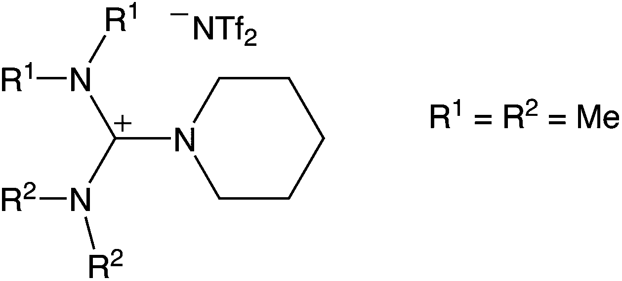 | ||
| Fig. 1 Structure of the applied guanidinium-based ionic liquid, [N11N11NpipGua]TFSI. | ||
CV and STM experiments, including handling and storage of the used substances, were performed inside a glove box under an argon atmosphere. During the transfer of the sample to the XPS chamber, air contact was inevitable due to the absence of an appropriate transfer vessel. Electrochemical investigations were carried out in self-designed cells made of KelF, each with a volume of 150 μl, and an Au(111) single crystal (MaTeck GmbH, Jülich, FRG) with a 12 mm diameter and Nd–Fe–B sintered square magnets with 10 mm edge lengths and 3 mm thickness (Vacuumschmelze GmbH & Co. KG, Hanau, Germany) acting as the working electrodes. Nd–Fe–B substrates were produced via sintering processes, resulting in rather rough surfaces. In this study, the calculated theoretical surface area was used for all charge determinations and current density evaluations, although the real surface area is supposedly larger. As counter and quasi-reference electrodes Pt wires (MaTeck GmbH, Jülich, FRG) were used; thus, all potentials are reported with respect to the Pt reference electrode. Prior to the measurements all electrodes (except Nd–Fe–B substrates) were annealed in a hydrogen flame and cooled down slowly in an argon stream.
All CVs were recorded with a Zahner IM6 potentiostat from Zahner Elektrik controlled by the Thales Z 1.20 USB software. Electrochemical in situ STM studies were performed with a Topometrix Discoverer TMX 2010. For the preparation of the STM tips, Pt/Ir wires (80:20) were electrochemically etched in 3.5 M NaCN and coated with BASF electrophoretic paint (ZQ84-3225) to reduce the faradaic current. All images were recorded in the constant-current mode with a tip current between 1–3 nA.
The elemental composition of the sample surfaces was determined by X-ray photoelectron spectroscopy (XPS) measurements using monochromatized Al Kα (1486.6 eV) radiation (PHI 5800 MultiTechnique ESCA System, Physical Electronics). A surface spot of 0.8 × 0.8 mm2 was used for all analyses. The measurements were performed with a detection angle of 45°, using pass energies at the analyzer of 93.9 and 29.35 eV for survey and detailed spectra, respectively. To calibrate the binding energies the C(1s) peak was set to 284.8 eV.
3. Results and discussion
3.1 Dy(OTf)3/N11N11NpipGuaTFSI on Au(111)
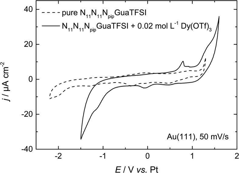 | ||
| Fig. 2 CV of N11N11NpipGuaTFSI (dashed line) and N11N11NpipGuaTFSI + 0.02 mol L−1 Dy(OTf)3 (solid line) on Au(111) at a scan rate of 50 mV s−1. | ||
In the positive potential region we observe a large anodic peak, whose related charge is comparable to the cathodic peak. Based on the CV measurements alone, one cannot clearly distinguish whether this peak is caused by oxidation of Dy or decomposition of the ionic liquid. However, previous studies in other types of RTILs1,8 claim the deposition of dysprosium to be an irreversible process, so we assume that the anodic process indicates more likely the oxidation of the ionic liquid. The comparison with the CV of the pure RTIL confirms this assumption, due to the increase of the current density at the positive reversal potential, which indicates the oxidation of the electrolyte.
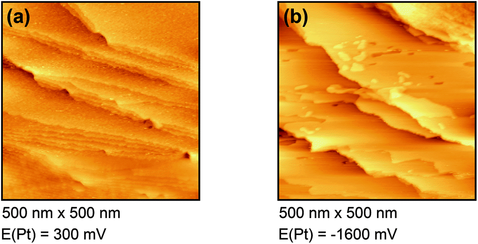 | ||
| Fig. 3 In situ STM images of Dy(OTf)3/N11N11NpipGuaTFSI on Au(111) at (a) 300 mV and (b) −1600 mV. | ||
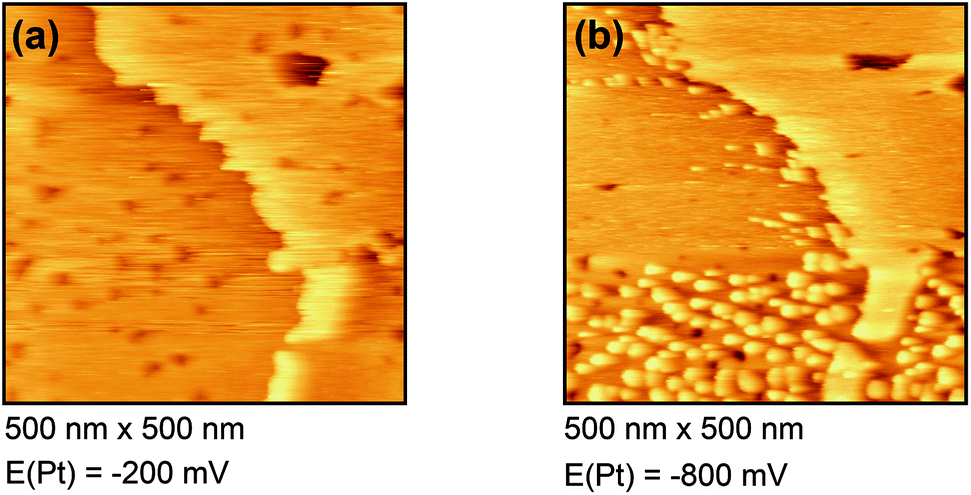 | ||
| Fig. 4 In situ STM images of Dy(OTf)3/BMITFSI on Au(111) at (a) −200 mV and (b) −800 mV. | ||
Fig. 4(a) shows the free Au surface at relatively positive potentials (−200 mV vs. Pt), comparable to Dy(OTf)3 in N11N11NpipGuaTFSI. After decreasing the potential the formation of islands can be observed (see Fig. 4(b)). The formation of the islands seems to start at step edges and then to spread over the Au terraces. The derived height of the islands from this STM image is approximately 300 nm.
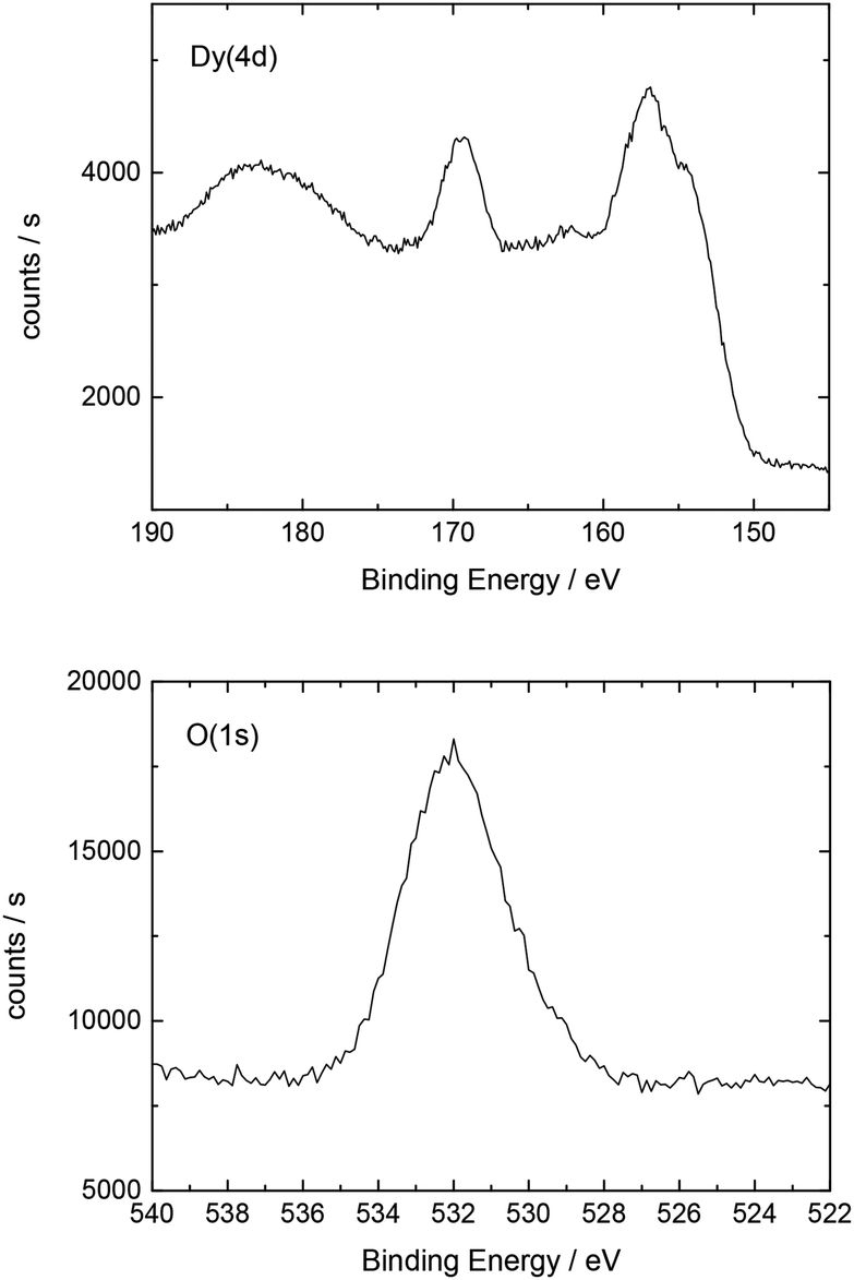 | ||
| Fig. 5 Detailed XP spectrum of the Dy deposit on Au(111). | ||
Additionally, Table 2 shows the determined atomic concentrations on the sample surface after electrochemical Dy deposition on Au(111). Here, the ratio of O/Dy is around 5, which is much higher than the expected value for stoichiometric Dy2O3. This observation has also been reported in the literature29 and could be due to the presence of excess oxygen on the surface of the deposited films, as mentioned before.
| O(1s) | C(1s) | F(1s) | Dy(4d) | S(2p) | Au(4f) |
|---|---|---|---|---|---|
| 51.0 | 16.3 | 15.7 | 10.6 | 5.0 | 1.4 |
3.2 Dy(OTf)3/N11N11NpipGuaTFSI on NdFeB
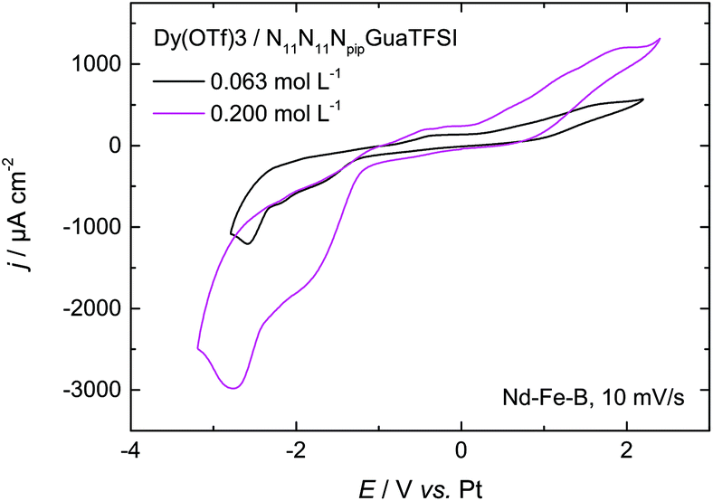 | ||
| Fig. 6 CV of 0.063 mol L−1 and 0.200 mol L−1 of Dy(OTf)3 + N11N11NpipGuaTFSI on Nd–Fe–B, recorded with a scan rate of 10 mV s−1. | ||
As the first attempt to increase the amount of deposited dysprosium, and thereby improve the permanent magnetic properties of the material, the concentration of the dissolved Dy salt in the RTIL was increased by a factor of 3. The red curve in Fig. 6 shows the CV of 0.200 mol L−1 of Dy(OTf)3/N11N11NpipGuaTFSI on Nd–Fe–B. Here, one can clearly notice an increase of the charge flow during the deposition process and dissolution, respectively. This also confirms the assumption of Dy oxidation at positive potentials of 0.2 V. The charge associated with the cathodic processes was enhanced from 60 mC cm−2 (Fig. 6, black curve) to 150 mC cm−2 (Fig. 6, red curve) over the same potential range, i.e. the charge and thus the amount of deposited Dy atoms (3 × 10¹⁷ per cm2) are almost tripled.
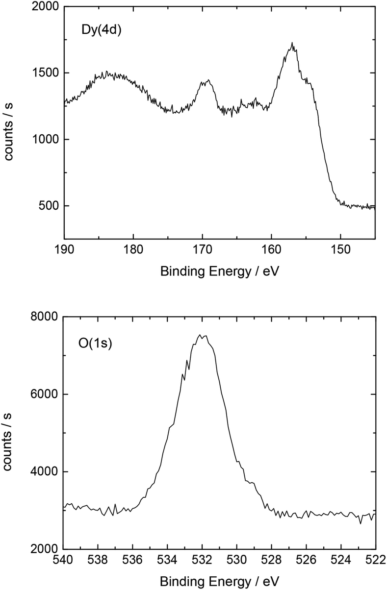 | ||
| Fig. 7 Detailed XP spectrum of the Dy deposit on the Nd–Fe–B magnet. | ||
Additionally, Table 3 shows the determined atomic concentrations on the sample surface after electrodeposition of Dy on Nd–Fe–B. Here, the ratio of O/Dy is around 2.5, which is again higher than the expected value for stoichiometric Dy2O3. We assume that this observation could be due to the presence of excess oxygen in the form of adsorbed OH-groups or carbonates on the surface of the deposited films or at least partial oxidation of the various components of the substrate.
| C(1s) | O(1s) | Dy(4d) | F(1s) | Fe(2p) | Nd(4d) |
|---|---|---|---|---|---|
| 47.2 | 32.3 | 12.6 | 6.3 | 1.1 | 0.5 |
3.3 Increasing Dy layer thickness on Nd–Fe–B
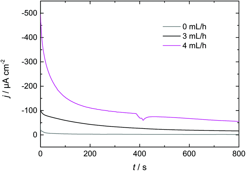 | ||
| Fig. 8 Flow rate dependence of I–t-transients during Dy deposition from Dy(OTf)3/N11N11NpipGuaTFSI on Nd–Fe–B. | ||
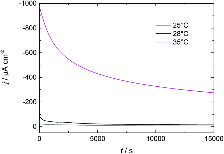 | ||
| Fig. 9 Temperature dependence of I–t-transients during Dy deposition from Dy(OTf)3/N11N11NpipGuaTFSI on Nd–Fe–B. | ||
4. Conclusions
In this paper we have investigated Dy electrodeposition from a tailored guanidinium-based RTIL on Au(111) as well as Nd–Fe–B substrates. In the presence of Au(111) we found that the reduction of Dy(III) to Dy(0) occurs in a single step at <−1 V vs. Pt. The reduction of Dy coincides with the formation of monoatomic high islands on the Au terraces which were observed in in situ STM and positively identified as Dy deposits on the Au(111) electrode surface in XPS measurements.A single reduction step at <−1 V vs. Pt was also observed in the presence of the Nd–Fe–B substrate, which is comparable to the behavior obtained for Au(111). The XP spectra confirmed the presence of Dy on the magnet's surface. We were able to enhance the thickness of the deposited Dy layer by either increasing the electrolyte flow or increasing the temperature. Thus, we expect that a combination of both approaches could be used to further optimize the thickness of the deposited Dy for industrial applications. This optimization could be realized via a temperature-controlled flow cell, resulting in improvements in the magnetic properties of the Nd–Fe–B substrate at a reduced energetic cost.
Acknowledgements
The authors thank Dr M. Rührig and Dr A. Kanitz for the supporting assistance and the Siemens AG for the financial support. The authors also thank the DFG (Deutsche Forschungsgemeinschaft) for their support through the Project KO 576/28-1 as well as the European Research Council through the ERC – Starting Grant THEOFUN (Grant Agreement No. 259608). Finally, we thank Dr T. Diemant (Institute of Surface Chemistry and Catalysis, Ulm University) for the XPS service measurements.References
- J. Lodermeyer, M. Multerer, M. Zistler, S. Jordan, H. J. Gores, W. Kipferl, E. Diaconu, M. Sperl and G. Bayreuther, J. Electrochem. Soc., 2006, 153, C242–C248 CrossRef CAS.
- N. Oono, M. Sagawa, R. Kasada, H. Matsui and A. Kimura, J. Magn. Magn. Mater., 2011, 323, 297–300 CrossRef CAS.
- M. Sagawa, S. Fujimura, H. Yamamoto, Y. Matsuura and K. Hiraga, IEEE Trans. Magn., 1984, MAG-20, 1584 CrossRef CAS.
- M. Sagawa, S. Fujimura, N. Togawa, H. Yamamoto and Y. Matsuura, J. Appl. Phys., 1984, 55, 2083–2087 CrossRef CAS.
- S. Hoenderdaal, L. T. Espinoza, F. Marscheider-Weidemann and W. Graus, Energy, 2013, 49, 344–355 CrossRef.
- K. Miura, M. Itoh and K.-I. Machida, J. Alloys Compd., 2008, 466, 228–232 CrossRef CAS.
- H. Sepehri-Amin, T. Ohkubo and K. Hono, J. Appl. Phys., 2010, 107, 09A745 CrossRef.
- G. Suppan, M. Ruehrig, A. Kanitz and H. J. Gores, J. Electrochem. Soc., 2015, 162, D382–D388 CrossRef CAS.
- K. R. Seddon, J. Chem. Technol. Biotechnol., 1997, 68, 351–356 CrossRef CAS.
- H. Tokuda, K. Hayamizu, K. Ishii, M. A. Bin Hasan Susan and M. Watanabe, J. Phys. Chem. B, 2005, 109, 6103–6110 CrossRef CAS PubMed.
- P. Nockemann, B. Thijs, N. Postelmans, K. V. Hecke, L. V. Meervelt and K. Binnemans, J. Am. Chem. Soc., 2006, 128, 13658–13659 CrossRef CAS PubMed.
- P. Nockemann, B. Thijs, S. Pittois, J. Thoen, C. Glorieux, K. V. Hecke, L. V. Meervelt, B. Kirchner and K. Binnemans, J. Phys. Chem. B, 2006, 110, 20978–20992 CrossRef CAS PubMed.
- B. Mallick, B. Balke, C. Felser and A.-V. Mudring, Angew. Chem., Int. Ed., 2008, 47, 7635–7638 CrossRef CAS PubMed.
- D. Prodius, F. Macaev, Y. Lan, G. Novitchi, S. Pogrebnoi, E. Stingaci, V. Mereacre, C. E. Anson and A. K. Powell, Chem. Commun., 2013, 49, 9215–9217 RSC.
- C. Lu, S. Das, N. Siraj, P. K. S. Magut, M. Li and I. M. Warner, J. Phys. Chem. A, 2015, 119, 4780–4786 CrossRef CAS PubMed.
- H. Kunkel and G. Maas, Eur. J. Org. Chem., 2007, 3746–3757 CrossRef CAS.
- F. Endres, ChemPhysChem, 2002, 3, 144–154 CrossRef CAS.
- R. D. Rogers and K. R. Seddon, Science, 2003, 302, 792–793 CrossRef PubMed.
- M. J. Earle, J. M. S. S. Esperanca, M. A. Gilea, J. N. Canongia Lopes, L. P. N. Rebelo, J. W. Magee, K. R. Seddon and J. A. Widegren, Nature, 2006, 439, 831–834 CrossRef CAS PubMed.
- F. Endres and S. Zein El Abedin, Phys. Chem. Chem. Phys., 2006, 8, 2101–2116 RSC.
- F. Endres, D. MacFarlane and A. Abbott, Electrodeposition from Ionic Liquids, Wiley-VCH, Weinheim, 2008 Search PubMed.
- M. Freemantle, An Introduction to Ionic Liquids, Royal Society of Chemistry, Cambridge, 2009 Search PubMed.
- A. Kurachi, M. Matsumiya, K. Tsunashima and S. Kodama, J. Appl. Electrochem., 2012, 42, 961–968 CrossRef CAS.
- W. Kantlehner, E. Haug, W. W. Mergen, P. Speh, T. Maier, J. J. Kapassakalidis, H.-J. Bräuner and H. Hagen, Liebigs Ann. Chem., 1984, 1984, 108–126 CrossRef.
- M. Gnahm, C. Berger, M. Arkhipova, H. Kunkel, T. Pajkossy, G. Maas and D. M. Kolb, Phys. Chem. Chem. Phys., 2012, 14, 10647–10652 RSC.
- N. Bucher, S. Hartung, M. Arkhipova, D. Yu, P. Kratzer, G. Maas, M. Srinivasan and H. E. Hoster, RSC Adv., 2014, 4, 1996–2003 RSC.
- H. Ogasawara, A. Kotani and B. T. Thole, Phys. Rev. B: Condens. Matter Mater. Phys., 1994, 50, 12332 CrossRef CAS.
- D. Barreca, A. Gasparotto, A. Milanov, E. Tondello, A. Devi and R. A. Fischer, Surf. Sci. Spectra, 2007, 14, 52–59 CrossRef CAS.
- A. P. Milanov, T. Toader, H. Parala, D. Barreca, A. Gasparotto, C. Bock, H.-W. Becker, D. K. Ngwashi, R. Cross and S. Paul, et al. , Chem. Mater., 2009, 21, 5443–5455 CrossRef CAS.
Footnote |
| † Electronic supplementary information (ESI) available. See DOI: 10.1039/C6NR01351A |
| This journal is © The Royal Society of Chemistry 2016 |