DOI:
10.1039/C5NR06718A
(Review Article)
Nanoscale, 2015,
7, 19764-19788
Recent advances in transition-metal dichalcogenide based nanomaterials for water splitting
Received
28th September 2015
, Accepted 5th November 2015
First published on 6th November 2015
Abstract
The desire for sustainable and clean energy future continues to be the concern of the scientific community. Researchers are incessantly targeting the development of scalable and abundant electro- or photo-catalysts for water splitting. Owing to their suitable band-gap and excellent stability, an enormous amount of transition-metal dichalcogenides (TMDs) with hierarchical nanostructures have been extensively explored. Herein, we present an overview of the recent research progresses in the design, characterization and applications of the TMD-based electro- or photo-catalysts for hydrogen and oxygen evolution. Emphasis is given to the layered and pyrite-phase structured TMDs encompassing semiconducting and metallic nanomaterials. Illustrative results and the future prospects are pointed out. This review will provide the readers with insight into the state-of-the-art research progresses in TMD based nanomaterials for water splitting.
 Fengmei Wang | Fengmei Wang received her BSc degree in Applied Chemistry from Hunan University in 2012. She is currently a PhD candidate under the supervision of Prof. Jun He at National Center for Nanoscience and Technology (NCNST), China. Her major research interests include synthesis and development of transition-metal chalcogenides for electrocatalytic and photocatalytic water splitting. |
 Tofik Ahmed Shifa | Tofik Ahmed received his BSc degree in Applied Chemistry from Arbaminch University, Ethiopia in 2007. He then obtained his MSc. degree in Analytical Chemistry from Haramaya University, Ethiopia in 2011. Currently, he is pursuing a PhD degree under the supervision of Prof. Jun He at National Center for Nanoscience and Technology (NCNST), Beijing, China. His research focuses on the controllable synthesis of layered transition-metal dichacogenides for water splitting. |
 Jun He | Prof. He received his PhD in Semiconductor Physics from the Institute of Semiconductors, Chinese Academy of Sciences (CAS), in 2003. Then he worked as a postdoctoral fellow at Applied Physics Department of Technische Universiteit Eindhoven, Netherlands, and Material Department of University of California, Santa Babara, USA. From 2007 to 2010, he worked at California NanoSystem Institute (CNSI), University of California, Los Angeles, USA, as a research scientist. He joined the “100-Talents” Program of CAS in Nov. 2010 and became a Full Professor of NCNST since then. Up to date, He is the author or co-author of more than 60 refereed papers. The total SCI citation times exceed 1000. |
1. Introduction
The development of viable and renewable energy is an inevitable issue for the scientific community due to the deleterious impact of fossil fuels on the environment and human health. The combustion of fossil fuels produces large quantities of pollutant gases, such as nitrogen oxides, carbon oxides and sulfur oxides and so on. For quite a long time, researchers have been trying to find renewable, clean and carbon-neutral energy sources in order to stave off catastrophic climate change. Hydrogen, having largest energy density, can be combusted to liberate energy without any harmful side products. A mol of hydrogen can produce 286 kJ energy through reaction with oxygen (2H2(g) + O2(g) → 2H2O(l) (ΔH = −286 kJ mol−1)). More importantly, hydrogen can be utilized as an energy carrier1–3 to store solar and electric energy via forming the chemical bond between two hydrogen atoms. Thus, the ever greenest approach to generate hydrogen can conspicuously solve the problem of the energy crisis. In industry, hydrogen is produced by steam reforming of natural gas (CH4(g) + H2O(g) → CO(g) + 3H2(g)).4 Nevertheless, this process usually consumes fossil fuels and releases CO2 gas. As a matter of fact, water is a well acknowledged resource for being the most plentiful supply of hydrogen that can be used to produce hydrogen via electrocatalytic5,6 or photocatalytic7–11 water splitting. The water splitting reaction, however, is an uphill process through which 237 kJ mol−1 of energy is required. In an electrochemical system, the external circuit usually provides the energy to realize splitting water including hydrogen evolution reaction (HER) and oxygen evolution reaction (OER).12,13 In this regard, the electrocatalysis can accelerate the rate of a chemical reaction through providing an alternative mechanism involving a different transition state and lower activation energy to reduce the electrochemical overpotentials.4,14–17 Precious noble metals or alloys, such as platinum (Pt), palladium (Pd), ruthenium (Ru) and iridium (Ir), have traditionally been the most efficient catalysts for water splitting in acid or alkaline electrolyte,18,19 but the low abundance and consequently high cost of such metals hinder their long-term viability. Therefore, efficient electrocatalysts comprised of earth-abundant materials for HER and OER are crucial for the development of water-splitting devices.
To date, earth-abundant transition-metal dichalcogenides (TMDs) with general formula MX2 (M = transition metal; X = chalcogen) including two-dimensional (2D) layered materials, such as MoS2, WS2, MoSe2, WSe2, TaS2 and TiS2etc., and pyrite phase structured TMDs (CoSe2, CoS2, NiS2, NiSe2, FeS2 and so on) are being developed at rapid pace for water splitting.20–27 In particular, featuring toward the 2D morphology and atomic thickness, these 2D layered MX2 nanosheets present some unusual physical, chemical or electronic properties compared to their bulk counterparts.6,24,28–32 Typically, each layer of them comprises three atomic layers with covalently bonded X–M–X and adjacent MX2 layers are coupled by weak van der Waals forces to form bulk crystals.33,34 In 2005, Jens Nørskov's group explored the HER mechanism on different catalysts through density functional theory (DFT) calculations.35 They found that the Gibbs free energy (ΔG) of MoS2 nanoparticles for HER is comparable to Pt, suggesting the potential HER property of MoS2. Subsequently, the edge of MoS2 nanosheet was experimentally confirmed to be electrochemically active.36 As such, experimental and computational studies demonstrate other 2D TMDs (WS2, MoSe2, WSe2, TaS2 and TiS2) are electrocatalytically active for H2 production. Unlike X–M–X layers in 2D layered TMDs, the family of cubic pyrite-type or orthorhombic macarsite-type structured TMDs shows the metal atoms are octahedrally bonded to adjacent chalcogen atoms. These TMD materials have been previously used as catalysts for ORR,37–39 HER40,41 and OER.42–45 The partial filling of the eg band was proved to contribute to their superior electrocatalytic activity.
From the perspective of photocatalysis, theoreticians46–48 put forward the promising photocatalytic ability of segmental semiconducting TMDs for solar water splitting. As it is obvious, the band gap of MoS2, typical TMD, increases dramatically when the thickness reduces from a few layers to an ideal monolayer. The single-layer MoS2 has the potential to split water under visible light. However, scalable synthesis of monolayer MoS2 nanosheets remains challenging. In line with this, these materials usually serve as cocatalysts in the photocatalytic system.49–53 Engineering advanced nanocomposites by designing hybrids with other materials is the most fascinating approach to overcome the shortcoming of individual counterparts as well as optimize their performance in photocatalytic water splitting. Moreover, the recent success in the synthesis of these TMD materials via various solution/vapor-process and scalable techniques offers great opportunities to construct functional nanostructures for hydrogen and oxygen evolution.
In this review, we briefly trace the strategies in TMD based nanomaterials applied in electrocatalytic and photocatalytic water splitting and give an overview of a clear understanding of basic knowledge, challenges and opportunities to point out the state-of-the-art in this field. We summarize major fabrication methods, describe some of the progresses and resulting achievements. Finally, we discuss the future prospects and afford some insights into the research directions in this area.
2. Synthesis of TMD based nanomaterials
The synthesis of TMDs with layer controllability and large-area uniformity is an indispensable requirement for practical application in water splitting. Meanwhile, exposing catalytically active sites of the TMDs should be considered by engineering the preparation process. Thus, great efforts have been devoted to generate high-quality TMD layers with a unique size, controllable thickness and excellent electronic structures. Nowadays, chemical exfoliation (top-down approach), solvothermal and chemical vapour deposition (both of which are bottom-up approaches) are frequently reported methods. Of these, individually or as a combination can be used to grow best performing TMDs. The following sections focus on the details of chemical exfoliation method, solvo(hydro)thermal method and chemical vapor deposition method.
2.1. Chemical exfoliation method
Tracing back to the discovery of graphene,54 the emergence of new physical properties are evident when a bulk crystal of macroscopic dimensions is thinned down to monolayer.55 This renders the opportunity to engineer the electronic structure. The bulk, unexfoliated, state of TMDs such as MoS2, WS2![[thin space (1/6-em)]](https://www.rsc.org/images/entities/char_2009.gif) 56,57 exist in Semiconducting 2H phases (trigonal prismatic) where most of the active sites are not exposed. This hinders their application in various fields. The M–X–M layers in TMD which are bound to each other by weak van der Waals forces can be exfoliated to further exploit the potential advantages.58,59
56,57 exist in Semiconducting 2H phases (trigonal prismatic) where most of the active sites are not exposed. This hinders their application in various fields. The M–X–M layers in TMD which are bound to each other by weak van der Waals forces can be exfoliated to further exploit the potential advantages.58,59
Liquid-phase exfoliation is advantageous over simple mechanical exfoliation owing to the formation of novel hybrid and composite materials; yet it is time consuming, environmentally unfriendly, and it is difficult to find appropriate solvents apart from resulting in structural deformation.60 Sonication assisted liquid-phase exfoliation61 appears to be a plausible route in so far the problem with solvent compatibility is addressed by using mixtures of solvents.
The product, however, is small in yield. The selection of solvents is very critical, and it is usually made based on Hansen solubility parameters (HSP) theory62,64,65 that would ultimately result in the minimum energy of exfoliation. The HSP theory predicts how well a material will dissolve in a given solvent or mixture of solvents and form a solution. Such prediction is made by taking three energy forms, namely the energy from dispersion forces (δd), the energy from dipolar intermolecular forces (δp) and the energy from hydrogen bonds (δh) as governing parameters into consideration. Assuming these three parameters as co-ordinates in a three dimensional space called Hansen space, the interaction radius (Ra) is calculated as an indicator to the distance between two molecules (eqn (1)). Accordingly, the nearer the two molecules are in this three-dimensional space; the more likely they are to dissolve in each other.
| | | Ra = [4(δD,solv. − δD,solu.)2 + (δP,solv. − δP,solu.)2 + (δH,solv. − δH,solu.)2)]0.5 | (1) |
Thus, the smaller Ra is the higher the expected solubility. It has been suggested that nanomaterials are most effectively dispersed in solvents with matching surface energy.61 Most often, a mixed solvent leads to a better result. In this case, each of the three HSP parameters can be obtained as a linear sum of the entities according to the following eqn (2).
| | | δmix = ∑ϕn, componentδn, component | (2) |
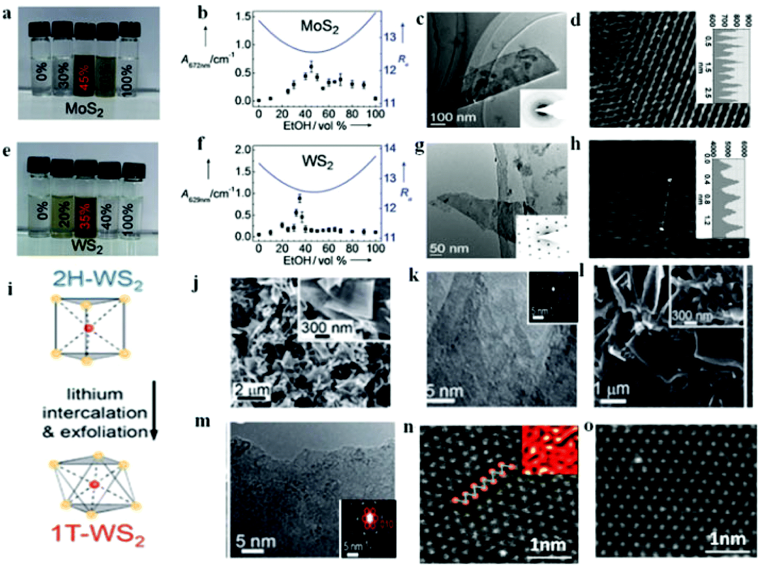
where
ϕ is the volume fraction for each composition. For instance, Zhou
et al.62 demonstrated that a mixture of ethanol and water can be designed to give high solubility for efficient exfoliation of MoS
2 and WS
2. Optimum ethanol–water ratio was set to achieve a stable suspension that does not precipitate under ambient conditions. Different ethanol–water mixtures have different
Ra value which in turn is related to the dispersion concentration. It is obvious from
Fig. 1a that 45 vol% ethanol–water is optimum condition for the MoS
2 case and therefore the smallest calculated
Ra is resulted in the highest dispersion concentration (
Fig. 1b). As such, the exfoliated nanomaterials in
Fig. 1c exist as thin sheets with sizes varying from 100 nm to several micrometers and more importantly the hexagonal lattices of the obtained MoS
2 nanosheets were not damaged during the mixed-solvent exfoliation process as evidenced from
Fig. 1d. In a similar fashion, the case of WS
2 also follows the same trend at 35 vol% ethanol–water (
Fig. 1e–h). In so far the application in HER is concerned, Li ion intercalation method is the most frequently reported technique that leads to high yield of the catalyst.
23,63,66–70 It mostly involves the reduction of butyllithium reagent which results in expansion of the lattice at the van der Waals gap thereby destabilizing the thermodynamically favored semiconducting 2H phase and eventually transforming to octahedral 1T phase.
Fig. 1i depicts the role of lithium intercalation chemistry deriving the phase transition from 2H to 1T of WS
2 nanosheet as reported by Lukowski and coworkers.
63 The high crystallinity of the multilayered structure was confirmed from the lattice-resolved high-resolution transmission electron microscopy (
Fig. 1j and k) and the 2H-WS
2 feature was indexed from the selected area electron diffraction (SAED) pattern (inset of
Fig. 1k). After intercalation, layered material was chemically exfoliated with excess water, resulting in individual 1T-WS
2 nanosheets. The high density of exposed edge sites was evidenced from the inset of
Fig. 1l revealing the more disordered and open structures. Though there are still untransformed 2H-WS
2 nanosheets, the presence of 1T-WS
2 nanosheet is confirmed from the superlattice structure observed in the SAED pattern (red circles inset of
Fig. 1m). This was corroborated by Voiry
et al.23 for the strained and chemically exfoliated WS
2 nanosheet. Such strain and zigzag-like local lattice distortion as shown in
Fig. 1n for the 1T phase of WS
2 is brought about by the Li intercalation and ultimately facilitated the HER process. Upon annealing, the 1T phase relaxed back to the thermodynamically favored 2H phase (
Fig. 1o). High yield (>80%) of metallic 1T phase MoS
2 nanosheets can be obtained using a solvent-free intercalation method. For example, Voiry and coworkers
70 used lithium borohydride (LiBH
4) to exfoliate bulk MoS
2 powder into single layered nanosheets from the solid-state intercalation reaction at 300 °C under argon environment. The yield in their case is significantly higher than the
n-butyllithium exfoliated MoS
2 (∼50%)
71 prepared at room temperature. Moreover, electrochemical lithiation is also another method reported to be advantageous over simple chemical intercalation by virtue of its relatively facile, room-temperature operation and provides high yield of products of single layer. In this particular method, the bulk TMD is set as cathode and lithium foil as anode in a Li-ion battery setup.
72 The galvanostatic discharge process with optimized conditions induces the lithium intercalation. Zhang's group
72 effectively optimized the cutoff voltage to prepare few-layered NbSe
2 and WSe
2 nanosheets. In their related report, single layers of high-yield MoS
2, WS
2, TiS
2, TaS
2 and ZrS
2, were successfully achieved.
73 This method eases the control of optimum amount of Li ion to be inserted as too low or too much Li insertion brings about serious deterioration in the final product. Upon lithium intercalation, charge impurities are vulnerable as a result of Li ions in TMDs. In fact, this kind of impurity is detrimental in electronics and especially in 2D materials.
74 It is therefore important to remove the excess charge from the surface by a simple method such as treating them with iodine dissolved in acetonitrile.
70
 |
| | Fig. 1 Photographs of MoS2 (a) and WS2 (e) dispersions in various ethanol–water mixtures. The absorbance of the MoS2 (b) and WS2 (f) suspensions in ethanol–water mixtures with different composition are shown as dots, and the calculated Ra values as solid lines. HRTEM image of MoS2. (c) and WS2 (g). Atomic resolution HRTEM image of MoS2 (d) and WS2 (h) (a–g, reproduced with permission from ref. 62. Copyright 2011 John Wiley & Sons, Inc.). (i) Simple lithium intercalation chemistry as used to drive the phase transformation from the 2H- to the 1T-WS2 polymorph. (j–k) Top-down SEM and HRTEM images of the as-grown 2H-WS2 nanostructures on W foil. (l–m) Top-down SEM and HRTEM images of chemically exfoliated WS2 nanosheets cast on graphite (i–m, reproduced with permission from ref. 63. Copyright 2014 The Royal Society of Chemistry). (n–o) High-resolution STEM images of an as-exfoliated WS2 monolayer showing regions exhibiting the 1T superlattice (n) and 2H structures (o) (reproduced with permission from ref. 23. Copyright 2013 Macmillan Publishers Limited). | |
2.2. Hydro(solvo) thermal method
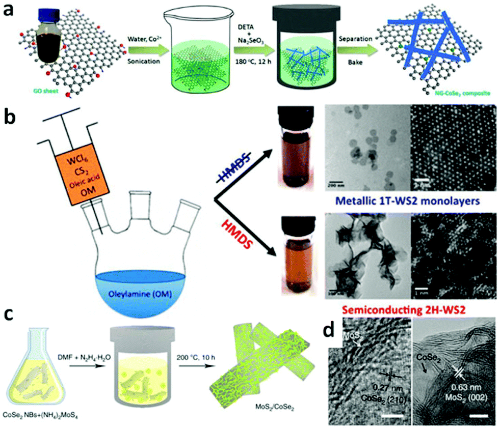
Hydrothermal method refers to purely heterogeneous reactions using water as media in a sealed steel pressure container with Teflon liners. It is capable of synthesizing advanced inorganic materials in high yield.75 Typically, the temperature of the hydrothermal process is in the range of 100–200 °C and the pressure is generated autogenously.76 The moderate temperatures together with the advantage of fast reaction kinetics and short processing time render it as a promising route to prepare homogeneous products in large scale effectively and economically.77 Based on those merits, as one type of advanced inorganic materials, TMD based nanomaterials with different shapes are widely fabricated by hydrothermal method recently.78–81 For example, it has been possible to successfully synthesize MoS2 nanoflowers,78 MoS2 microspheres,79 CoS2 nanowires,80 and CoS2 nanoparticles,83 which all display great potential for application of water splitting. To further improve their catalytic activity, composites that hybrid TMDs with other conductive or porous materials have been synthesized. MoS2 nanosheets have successfully been grown on carbon fiber (CF),84,85 graphene oxide (GO),88 and Mo meshes.82 As conductive materials, CF and GO can facilitate electron transportation. Furthermore, the MoS2 nanostructure grown on these three-dimensional (3D) CF, GO and Mo meshes can expose more active sites. These design principles can also be applied to other members of TMDs.89,90 For instance, CoSe2 nanowires array on carbon cloth (CoSe2 NW/CC)89 and nitrogen-doped graphene supported CoSe2 nanobelt composite (NG–CoSe2 composite) were prepared.44Fig. 2a is a schematic illustration of the hydrothermal process to fabricate NG–CoSe2 hybrid composites. Typically, the mixture of Co(AC)2·H2O and GO was sonicated for about 10 min followed by the addition of diethylenetriamine (DETA) and Na2SeO3. This new mixture was homogenized, heated to 180 °C and kept for 12 h to yield CoSe2 nanobelts which were anchored to the NG sheets.
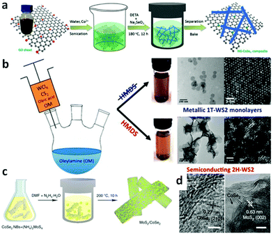 |
| | Fig. 2 (a) Schematic illustration of the formation of nitrogen-doped graphene supported CoSe2 nanobelt composite (reproduced with permission from ref. 44. Copyright 2014 American Chemical Society). (b) Schematic solvothermal process to synthesize WS2 nanosheets, low-magnification TEM images and HAADF-HRSTEM images of 1T-WS2 nanosheets and 2H-WS2 nanosheets (reproduced with permission from ref. 86. Copyright 2015 American Chemical Society). (c) Schematic illustration of solvothermal synthesis with CoSe2/DETA nanobelts as substrates for preparation of MoS2/CoSe2 hybrid. (d) HRTEM images of MoS2/CoSe2 hybrid showing distinguishable microstructures of MoS2 and CoSe2 (reproduced with permission from ref. 87. Copyright 2015 Macmillan Publishers Limited). | |
Solvents other than water can also be employed accounting for the fact that organic solvents have various specific physico-chemical properties such as polarity, viscosity, softness, which all can affect the solubility and transport behavior of the precursors during the synthetic process.91 The shape, size and phases of the final samples can be controlled in these solvents.91 The most important aspect of solvothermal method is that it prevents the samples from oxidizing; hence this method can be used to prepare various non-oxides, such as TMD based nanomaterials.22,92–94 With this method, Benoit et al. have synthesized 1T-WS2 and 2H-WS2 nanosheets (Fig. 2b).86 To obtain 1T-WS2 nanosheets, they degassed oleylamine (OM) in a three-neck flask for 1 h under vacuum at 65 °C and then heated up to 320 °C under argon atmosphere. Next, the mixture of OM, WCl6, oleic acid and CS2 was injected dropwise into the OM solution over a 30 min interval. As shown in Fig. 2b, the synthetic process of 2H-WS2 nanosheets is similar, except a further procedure, adding hexamethyl disilazane (HMDS) into the OM after degassing the solution. The 1T-WS2 nanosheets are monodispersed with diameter of about 100 nm whereas that of the 2H-WS2 nanosheets are aggregated and some of them are still flower-like. Highly scalable MoS2 nanostructures have also been fabricated on CF,95 and graphene94,96,97 to construct efficient electrocatalysts via this method. To prepare the MoS2 nanoparticles on reduced graphene oxide (MoS2/RGO) hybrid,96 (NH4)2MoS4 and graphene oxide (GO) were mixed in N,N-dimethylformamide (DMF) solvent and then the mixture was sonicated to form a clear and homogeneous solution. After heating the reaction solution at 200 °C for 10 h, uniformly laid MoS2 nanoparticles on rGO sheets resulted with size of around 5 nm. Other composite materials can also be synthesized by using a solvothermal method which renders the synergetic chemical coupling effects between the components making up the composites. Yu's group successfully synthesized the uniform CoSe2 nanobelts through the reaction between Co(Ac)2·H2O and Na2SeO3 in DETA at 180 °C with lengths of several tens of micrometers and widths of from 100 to 500 nm.98 Due to the copious amino groups on the CoSe2/DETA surface, which serve as the nucleation sites, some other inorganic precursors can anchor on the CoSe2/DETA to nucleate and grow under solvothermal method. For this reason, they hybridized their CoSe2 nanobelts with Mn3O4 nanoparticles (Mn3O4/CoSe2),42 Ni/NiO nanoparticles (Ni/NiO/CoSe2)99 and MoS2 nanosheets (MoS2/CoSe2).87Fig. 2c displays a schematic illustration of solvothermal synthesis of MoS2/CoSe2 hybrid with CoSe2/DETA nanobelts as substrates. During the synthesis, CoSe2/DETA nanobelts and precursors were mixed and sonicated, followed by heating at 200 °C for 10 h. From the high-resolution transmission electron microscopy (HRTEM) images of MoS2/CoSe2 hybrid (Fig. 2d), it can be seen that the uniform MoS2 nanosheets tightly combined with CoSe2 nanobelts. A similar procedure was employed for the synthesis of Mn3O4/CoSe242 and Ni/NiO/CoSe299 nanomaterials.
2.3. Vapor-phase deposition method
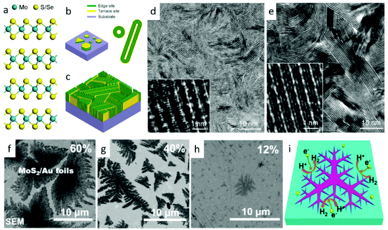
Vapor-phase deposition methods, including sulfurization (or selenization) reaction with metal or metal oxide,102–113 thermal decomposition of thiosalts,114 and vapor-phase transport recrystallization from powders,115–117 are extensively utilized to controllably synthesize TMDs.118 Generally, this method realizes the growth of TMD nanostructures with large scale and high quality on the different substrates for hydrogen or oxygen evolution. The superior interfaces between nanostructures and substrates are in favor of charge transportation. What's more, by adjusting the ratio of precursors, the component of products could be easily controlled to improve the physical and chemical properties.119,120 With these merits, researchers have proposed a great many projects to increase the catalytic activity of TMDs for water splitting via vapor deposition routes. One tendency is to design nanostructures with huge numbers of active sites. For example, Cui's group100 designed a rapid sulfurization/selenization process to convert Mo thin film to a distinctive structure of vertical aligned MoS2 and MoSe2 films on several kinds of substrates. As shown in Fig. 3a–e, vertical structures greatly gain the exposed edges of MoS2 and MoSe2 nanosheets. During this growth process, the sulfurization or selenization conditions play a crucial role in determining the growth direction.
 |
| | Fig. 3 (a) Layered crystal structure of molybdenum dichalcogenide. (b) Schematics of MoS2 nanoparticle with platelet-like morphology distributed on a substrate (left), and nanotubes and fullerene-like nanotubes of MoS2 and MoSe2 (right). (c) Idealized structure of edge-terminated molybdenum dichalcogenide films with the layers aligned perpendicular to the substrate, maximally exposing the edges of the layers. TEM image of a MoS2 film (d) and a MoSe2 film (e) produced by rapid sulfurization/selenization, clearly showing exposed edges. High-resolution TEM image (inset) reveals individual layers consisting of three atomic planes in the sequence of S–Mo–S or Se–Mo–Se atomic planes (reproduced with permission from ref. 100. Copyright 2013 American Chemical Society). (f–i) HER activity of dendritic monolayer MoS2 flakes transferred onto Au foils. (f–g) SEM images of monolayer MoS2 flakes on Au foils with coverages of 60, 40 and 12% and domain sizes of ∼10 μm, ∼5 μm and ∼800 nm (in envelope edge length), respectively. (i) Schematic view illustrating the edges of fractal monolayer MoS2 flakes as active catalytic sites for HER (reproduced with permission from ref. 101. Copyright 2014 American Chemical Society). | |
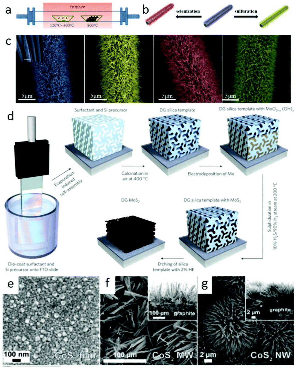
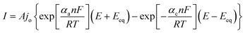
At a high temperature, the much slower rate of S/Se atoms diffusing into the deposited Mo films than that of chemical conversion renders it as the rate-limiting process. On the other hand, the anisotropic structure of MoS2/MoSe2 leads to S/Se atoms diffusion along the layers faster than that across the layers.100 These two factors jointly result in the formation of such vertical structures, which greatly gain the exposed edges. Analogously, they obtained a similar structure of MoSe2 and WSe2 films on curved and rough substrates (Si nanowires and carbon fiber paper), which exhibited significantly improved HER activity than that on the flat ones.123 Benefiting from the higher surface energy of pure Si substrate, Yang and coworkers21 realized an edge-abundant MoS2 nanobelts structure with their basal plane vertical to the substrates. Since the surface was fully covered by edge sites, a high HER efficiency was achieved. Besides the vertical ones, other nanostructures with abundant edges are synthesized via vapor deposition method. For instance, by carefully choosing single-crystal SrTiO3 as substrates, Liu's group101 developed a low-pressure chemical vapor deposition (LPCVD) approach to controllably grow dendritic monolayer MoS2. As depicted in Fig. 3f, those nanoflakes were decorated with plentiful edges, much more than that of the common triangular ones. These dendritic MoS2 nanostrucures could be transferred to Au foil for further application in water splitting. Additionally, the construction of 3D hierarchical TMD structures with large surface area is also popular. Some flexible carbon fibers or porous substrates have been used for this purpose. Recently, we successfully29,124 grew 3D WS2 and WSe2 nanotubes (NTs) on carbon fibers through in situ sulfurizing/selenizing WO3 nanowires125 as depicted in Fig. 4a and b. On the basis of these results, component-controllable WS2(1−x)Se2x NTs were also synthesized to modify its physical and chemical properties. The large surface area of as-grown NTs, the layer dislocations, defects and local strains existing on the walls of the NTs (Fig. 4c) are the dominant active sites for electrocatalytic water splitting. Similar 3D hierarchical structures of other TMDs like CoSe2 and MoS2 have also been reported for being successfully synthesized with this method and applied for highly sensitive HER catalysis.126,127 Compared with carbon fibers, porous substrates are able to offer greater contact area and load with more TMD nanomaterials. Jaramillo's group121 developed a method to synthesize double-gyroid MoS2 by sulfurization of Mo films, which were electrodeposited on a silica template. After that, the silica templates were dissolved by etching with a 2 wt% hydrofluoric acid solution and eventually the bicontinuous inverse double-gyroid MoS2 network with a higher surface area was obtained. The schematic procedure is depicted in Fig. 4d. Although it exhibited superior activity for electrocatalysis, the absence of direct contacts between the electrodes and the catalysts may impede its further improvement of properties. Thus, it is important to grow the materials directly onto conductive porous templates. Chang et al.128 developed a method to formulate MoSx (x ≥ 2) on graphene protected Ni foam through the thermolysis of ammonium thiomolybdates. The MoSx/graphene/3D Ni foam structure showed excellent HER efficiency. Similarly, Tan et al. utilized 3D nanoporous gold as supports to synthesize monolayer MoS2 films and applied them for HER.129
 |
| | Fig. 4 (a) Schematic diagram of the experimental setup of the fabrication of WO3 NWs and WS2, WSe2 and WS2(1−x)Se2x NTs. (b) Schematic diagram of WO3 NWs converting to WS2 and WSe2 NTs on carbon fibers by sulfuration and selenization. (c) Magnified SEM images of WO3 NWs, WS2, WSe2 and WS2(1−x)Se2x NTs (from left to right) (reproduced with permission from ref. 29. Copyright 2014 American Chemical Society). (d) Synthesis procedure and structural model for mesoporous MoS2 with a double-gyroid (DG) morphology (reproduced with permission from ref. 121. Copyright 2012 Macmillan Publishers Limited). SEM images of (e) a polycrystalline CoS2 film, (f) CoS2 MWs and (g) CoS2 NWs on graphite (with cross-sectional SEM images inset in the corresponding panels) (reproduced with permission from ref. 122. Copyright 2014 American Chemical Society). | |
Some pyrite phase structured TMDs, such as CoSe2, CoS2 and NiS2 nanostructures have been achieved by vapor deposition method. CoSe2 nanoparticles on carbon cloth were prepared through seleniding cobalt oxide nanoparticles by Cui's group.41 Faber et al.122 reported that CoS2 film, nanowires and microwires were synthesized on graphite or glass substrates via sulfurizing Co films, β-Co(OH)2 microwires and Co(OH)(CO3)0.5·xH2O nanowires in S vapor atmosphere. Fig. 4e–g display the SEM images of as-grown CoS2 films, nanowires and microwires on graphite. All the results verified the CoX2 (X = S, Se) as high performance electrocatalyst and their potential for large-scale application of renewable energy. Besides, other earth-abundant metal pyrites (FeS2, NiS2) and their alloys have also been synthesized and examined as promising alternative electrocatalysts for both HER and ORR.40,130,131 In brief, vapor deposition is an effective method to produce TMDs nanostructures with designed morphology and components, which are promising for application of water splitting.
3. Properties and application in water splitting
3.1. Electrocatalytic water splitting
As an advanced technology for clean energy conversion, water electrolysis is a subject of both extensive fundamental and utilitarian studies. The core of this technology is a series of electrochemical processes. Typically, in the electrocatalysis of water, the HER and OER processes occur at the cathode and anode of an electrolytic cell to produce gaseous molecular hydrogen and oxygen, respectively (eqn (3)).132 These processes are as follows:| |  | (3) |
The hydrogen evolution reaction (HER) is perhaps the most studied electrochemical reaction and is of prominence for applications such as energy storage via H2 production. It has been well established96,133 that HER proceeds via two successive steps: discharge of proton to give adsorbed H atom (Volmer reaction) followed by either a combination of two H atoms (Tafel reaction) or combination of an adsorbed hydrogen atom with a proton and an electron (Heyrovsky reaction). These different kinds of steps of HER134,135 are involved depending on the nature of the electrode and media of the electrolyte under investigation (Table 1). To be a good HER catalyst, it should have neither too weakly nor too strongly adsorbed H* on to M, having an optimal free energy of H adsorption close to zero.136
Table 1 Mechanism of HER catalysis in acidic and basic mediaa
| Processes |
Acidic media |
Basic media |
|
*M denotes the electrode surface.
|
| Volmer reaction |
H+ + M + e− → M − H* |
H2O + M + e− → M − H* + OH− |
| Heyrovsky reaction |
M − H* + H+ + e− → M + H2 |
M − H* + H2O + e− → M + OH− + H2 |
| Tafel reaction |
2M − H* → 2M + H2 |
2M − H* → 2M + H2 |
Unlike HER, anodic OER, as an indispensible half reaction involved in water splitting, includes four proton-coupled electron transfers and oxygen–oxygen bond formation, which is much more kinetically sluggish and challenging. In acidic conditions, two water molecules are oxidized and separated into four protons (H+) and one oxygen molecule (O2) through losing four electrons (eqn (4)). Likewise, the oxidation of hydroxide ions takes place in alkaline solution producing O2 and H2O with the same number of electrons being evolved (eqn (5)).
| | | 2H2O → 4H+ + O2 + 4e− (in acidic electrolyte) | (4) |
or
| | | 4OH− → 2H2O + O2 + 4e− (in basic electrolyte) | (5) |
Eqn (4) and (5) suggest that the generation of an O2 molecule requires a transfer of four electrons. However, the multiple electron transfer at same time is not kinetically favorable. Some results reveal that the OER involves multiple steps with one electron transfer per step.137 The four possible reaction mechanisms in basic media are listed in Table 2.
Table 2 The possible OER mechanisms in basic mediaa
| Mechanism I |
Mechanism II |
| 1. 2OH− → 2OH + 2e− |
1. 2OH− → 2OH + 2e− |
| 2. 2OH + 2OH− → 2O− + 2H2O |
2. 2OH + 2OH− → 2O− + 2H2O |
| 3. 2O− → 2O + 2e− |
3. 2O− + 2MOx → 2MOx+1 + 2e− |
| 4. 2O → O2 |
4. 2MOx+1 → 2MOx + O2 |
| Mechanism III |
Mechanism IV |
|
*M denotes the electrode surface.
|
| 1. 4OH− + M → 4M − OH + 4e− |
1. 2OH− → 2OH + 2e− |
| 2. 4M − OH → 2MO + 2M + 2H2O |
2. 2OH + 2OH− → 2H2O2− |
| 3. 2MO → 2M + O2 |
3. 2H2O2− → O2− + 2H2O |
| 4. 2O2− → O2 + 2e |
Generally, HER and OER obey the Butler–Volmer model even with very high overpotentials. During electrolysis, the potential (E) where reaction takes place is different from Nernstian potential (Er) and the difference between the two potentials corresponds to the extra energy than thermodynamically expected to drive the reaction. This potential is called the overpotential (η, eqn (6)).
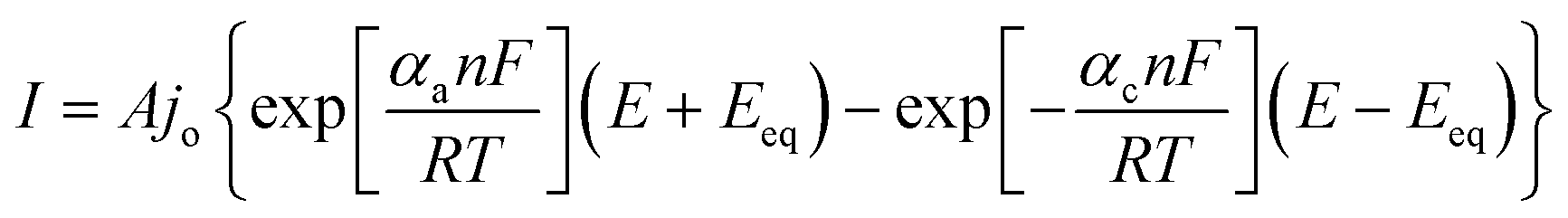
In line with this, potential of interest (onset potential, or potential at certain current density), exchange current density, and Tafel slope are the most frequently reported parameters to evaluate HER catalysts. These parameters can be extracted from the current–potential relationship curve, particularly known as the polarization curve. The potential where the first catalytic current observed is called the onset potential, above which the current increases rapidly. More often, a specific potential corresponding to unambiguous current density is employed as a catalyst performance measurement. In this respect, the potential required to afford a current density of 10 mA cm−2 is usually reported as it corresponds to the cost competitive photoelectrochemical water splitting efficiency of 12.3%.138 Other equally important parameters are the Tafel slope and the exchange current density. The Tafel equation133 represents the commonest range of overpotential and current densities providing information about kinetics of charge transfer process vis-à-vis the additional voltage required, with units usually expressed as mV per decade (mV dec−1) of current. The relationship between current and potential was exploited and given by Butler–Volmer equation (eqn (7))
| |  | (7) |
where
A is the electrode active surface area,
α is the charge transfer coefficient. At considerable overpotential on the electrode surface, the equation simplifies to Tafel equation (
eqn (8)):
| | | η = a − blogj | (8) |
where
b is Tafel's slope, gives information on the mechanism of the electrode reaction and
j is the current density given by
eqn (9):
| |  | (9) |
The exchange current density can be extracted from the Tafel curve, revealing the flow of charge or electron at equilibrium. It normally assumes a very low value due to the unavailability of net current at equilibrium signifying the extent of oxidation or reduction that may occur. The lower the exchange current density signifies the higher the overvoltage that must be applied to create a significant net current flow. In general, low overpotential, high exchange current density and small Tafel slope are characteristics of good electrocatalysts.
In the past few years, thanks to the remarkable advances in the nanotechnology and computational chemistry, TMDs have gained widespread attention for the design of novel electrocatalysts for HER and OER due to their unique chemical and physical properties. Herein, TMD based electrocatalysts are highlighted for hydrogen and oxygen evolution in an electrolytic cell.
3.1.1. HER catalyzed by TMD based nanomaterials.
In the subsequent sections, the HER performances of layered TMDs (focusing on molybdenum and tungsten dichalcogenide based electrocatalysts) and pyrite phase TMDs (focusing on iron, cobalt and nickel dichalcogenide based electrocatalysts) will be surveyed with particular attention vested on the strategies to substantiate a better performance.
3.1.1.1. Molybdenum dichalcogenide based electrocatalysts.
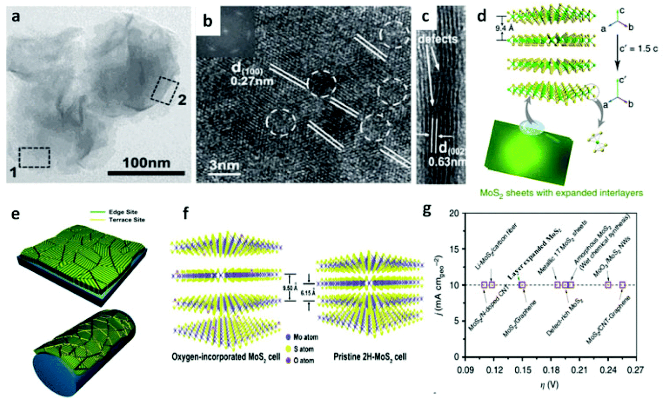
Following the discovery of graphene, molybdenum based dichalcogenides138–140 are the most widely investigated materials owing to their exciting prospects in HER catalysis among all TMD based nanomaterials. Inspired by the effective catalysis ability of hydrogenases and nitrogenases for hydrogen evolution reaction, Hinnemann et al. theoretically made the biomimetic speculation of Mo based materials to be active in HER.35 The comparison among the free energies (ΔGH) of atomic hydrogen bonding to the catalyst on different materials with that on the common enzymes in Fig. 5a shows that materials that form strong bonds (Ni and Mo) with atomic H or those that do not bind to atomic hydrogen (Au) should be excluded from the expectation to be good HER catalysts. However, bearing a resemblance to the enzymes, MoS2 is a promising candidate for replacing Pt owing to the existence of active site on the edges. Experimentally, the electrocatalytic activity36 linearly correlates with the length of edge sides as quantified from the scanning tunneling microscopy (Fig. 5b and c) and found to be independent of the MoS2 area coverage (Fig. 5d and e). Thus, activities from amorphous to nanocrystal MoS2 with various shapes have been reported so far and still continues to flourish with impressive advances.138,141 Furthermore, the HER activity of MoS2 is dependent on the size and number of layers, as reported by Seo et al.142 Nanoscale dimension at monolayer precision level provides increased performance. Generally, exposing much more edges and increasing the conductivity of MoS2 are the two main strategies pursued for improving its HER performance. The basal planes of 2D MoS2 usually suffer from the paucity of active sites for HER. There are various strategies developed to expose active sites on such materials.21,121,143 Among them, inducing defects into the crystal structure of MoS2 can bring about additional active edge sites emanating from the cracks on MoS2 nanosheets.144 From Fig. 6a, the ultrathin nature of MoS2 nanosheets was confirmed from the TEM image. The direction of individual (100) planes of hexagonal MoS2 slightly differs from one another (Fig. 6b and c). This suggests the disordered atomic arrangement leading to cracking of the basal planes, and thereby formation of additional edges, and eventually resulting in the considerably high HER performance. Yang and coworkers21 reported the HER performance of single-crystal MoS2 nanobelts. The top surface of the nanobelt is composed of vertically positioned basal plane edges. Such extreme exposure of edges make the material optically active, as it quenches all of the indirect band gap excitons, and also electrochemically active from the observed current density of 20 mA cm−2 at overpotential of 170 mV in acid electrolyte (0.5 M H2SO4). From the report by Rui and coworkers, it is evident that enlarged spaces endowed by modifying the interlayer spacing can alter the electronic structures of the edge-terminated MoS2 colloid nanostructure, leading to improved performance. After expanding the interlayer spacing of MoS2 to 9.4 Å (Fig. 6d), a fast kinetics of HER with onset potential of 103 mV and Tafel slope of 49 mV dec−1 was achieved.145 The report by Lewis et al.146 is also exemplary in so far exposing active site is concerned. They directly prepared porous MoSe2 film on glassy carbon electrode through an operando method. This film features better HER performance than the smooth film. Moreover, improving the conductivity of MoS2 through hybrids with other conductive materials or in atomic level is also popular to promote the HER performance. Molybdenum dichalcogenides based hybrid structures via enhancing the conductivity can increase the HER performance. For instance, MoO3/MoS2 core–shell nanowires,147 MoS2/3D-CFs,148 MoS2/CNT-graphene,149 MoS2/N-doped carbon nanotube,150 MoS2/Au,151 MoS2/rGO,96,152 MoSe2/graphene,153 MoSe2/SnO2154 and MoSe2/rGO155 exhibited superior electrocatalytic activity in the HER relative to the single-component catalysts. The synergisms are more pronounced from a well matched vertical orientation, availing much more surface area, and ease of electron transport. This feature is typically substantiated from the report by Wang et al. who synthesized vertically oriented MoS2 on curved123 and 3D substrate.156 As compared to the flat substrate, the curved substrate (Fig. 6e) could increase the surface area, maximize the exposed edge sites and induce strain through expanding or squeezing the molecular layers, thereby changing the electronic structures of the films.157 More importantly, simultaneously enhancing the intrinsic conductivity and the active site exposure is crucial to boost the HER performance. Such dual advantage brought by structural and electronic modification was reported by Xie's group.158 They controllably incorporated oxygen in ultrathin MoS2 nanosheets and obtained a disordered structure whose unsaturated sulfur atoms flourished abundantly. Oxygen incorporation enlarged the interlayer spacing (Fig. 6f) and hence improved the conductivity. The HER performance with a current density of 126.5 mA cm−2 at overpotential of 300 mV (in 0.5 M H2SO4) exhibited by oxygen incorporated MoS2 is reported to be 60 times larger that of the bulk MoS2. Such significant enhancement is due to the more active sites, disordering, and conductivity, expanded interlayer spacing.158 The comparison of different MoS2 based materials is depicted in Fig. 6g.
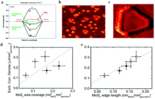 |
| | Fig. 5 (a) Calculated free energy diagram for hydrogen evolution (reproduced with permission from ref. 35. Copyright 2005 American Chemical Society). (b) STM image of high coverage MoS2 nanoparticles on Au(111) (c) STM image of high coverage atomically resolved MoS2 particle. (d) Exchange current density versus MoS2 area coverage. (e) Exchange current density versus MoS2 edge length (reproduced with permission from ref. 36. Copyright 2007 American Association for the Advancement of Science). | |
 |
| | Fig. 6 (a) TEM images of defect-rich MoS2 ultrathin nanosheets. (b–c) HRTEM image areas 2 and 1, respectively [(a–c) reproduced with permission from ref. 144. Copyright 2013 John Wiley & Sons, Inc.]. (d) Schematics of enlarged layer space in MoS2 (reproduced with permission from ref. 22. Copyright 2015 Macmillan Publishers Limited). (e) Molybdenum chalcogenide nanofilm with molecular layers vertically standing on a flat and curved substrate. The green color represents the edge sites, and the yellow color represents the terrace sites. The edges are maximally exposed on the curved surface (reproduced with permission from ref. 123. Copyright 2013 American Chemical Society). (f) Schematic for the oxygen-incorporated MoS2 with enlarged interlayer spacing and the pristine 2H-MoS2 (reproduced with permission from ref. 158. Copyright 2013 American Chemical Society). (g) Comparison of overpotential required to generate a current density of 10 mA cm−2 on various MoS2-based catalysts (reproduced with permission from ref. 22. Copyright 2015 Macmillan Publishers Limited). | |
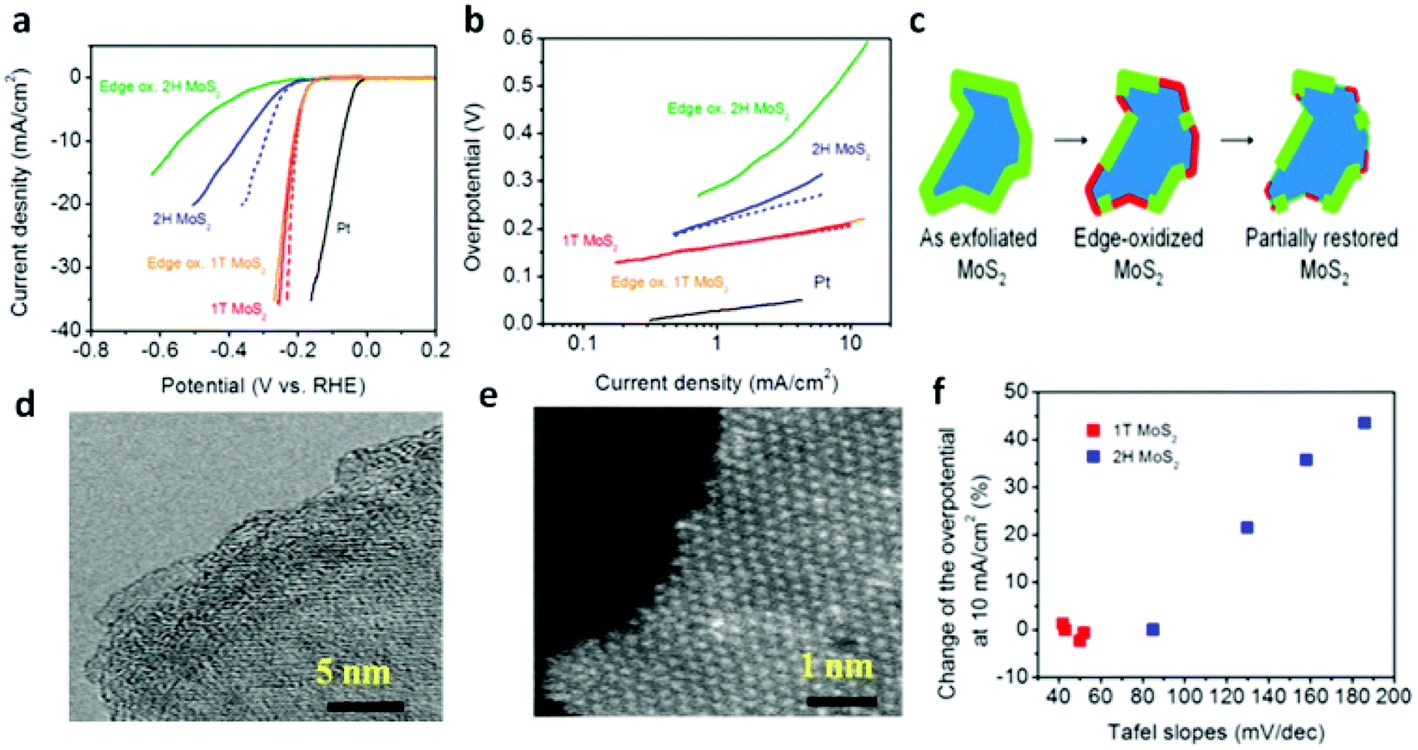
The design of ternary structures, such as incorporating another chalcogen element,159–162 such as MoS2xSe2(1−x), inaugurates the possibility of tuning the composition. Interestingly, these ternary TMDs demonstrate better HER performance than the binary counterparts. From theoretical perspectives, the free energy of H adsorption is weaker (80 meV) on sulfided Mo edges as compared to selenided Mo edges (−140 meV). Thus, controllably adjusting the S/Se ratio to thermoneutral (ΔGH ≈ 0) leads to more feasible edges for HER.161 In this respect, Gong et al.161 followed a solution method to synthesize MoS2(1−x)Se2x nanoflakes at low temperature and in high yields demonstrating better activity than either MoS2 or MoSe2. Similarly, doping of Co into MoS2 is proved to enhance the catalytic activity of MoS2via decreasing the ΔGH from the S-edge side.142,163 The shape of MoS2 crystal changes from truncated triangle to hexagonal upon incorporation of Co thereby giving rise to Co-binding S-edges, which is more catalytically active.164 It is noteworthy that the development of Mo dichalcogenides based electrocatalysts has reached a fascinating stage by phase transformation of the electrocatalyst.68,156 Owing to its metallic nature (mentioned above), 1T-MoS2 nanosheet endows a facile electron kinetics, excellent electrical transport and proliferation of catalytic active sites. Consequently, as can be seen from Fig. 7a and b, the HER performance of 1T MoS2 is better than that of the 2H phase.70 It has been suggested that the edge sites are not the main active sites for 1T phase unlike the thermodynamically favored 2H-phase. As proof of concept, partial oxidation of the edges was conducted to bear out the fact that the HER catalytic activity of 1T-MoS2 relies on the basal plane unlike that of 2H-MoS2. As is evident from the schematic and the TEM images (Fig. 7c–e), the edges are highly disordered after oxidation, while the basal plane of the nanosheets remains unaffected. Accordingly, the electrochemical oxidation of the edges led to a dramatic reduction in catalytic activity for 2H nanosheets, but the catalytic performance was unaffected by oxidation for 1T phase nanosheets. The overall performance of the oxidized 2H-MoS2, however, improved after volumetric cycling in Fig. 7f, indicating that its catalytic activity from the edges was partially re-established. These facts brought the conclusion that the basal plane is catalytically active for 1T-MoS2.
 |
| | Fig. 7 (a) Polarization curves of 1T and 2H MoS2 nanosheet electrodes. (b) Corresponding Tafel plots. (c) Schematic of the oxidation process and partial restoration of the nanosheet edges after several voltammetric cycles. (d) High-resolution TEM (e) and HAADF STEMof edge-oxidized MoS2 nanosheets showing corrugated edges caused by the chemical oxidization. (f) Variation of overpotential at 10 mA cm−2 and Tafel slopes for 1T and 2H MoS2 (reproduced with permission from ref. 70. Copyright 2013 American Chemical Society). | |
In general, the strategies employed so far for enhancing HER performance of molybdenum dichalcogenides based electrocatalysts include engineering of active edge sites or interlayer distances, hybridization with other conducting materials, addition of secondary metals or chalcogens, and the formation of 1T phase.
3.1.1.2. Tungsten dichalcogenide based electrocatalysts.
Owing to the structural resemblance between WS2 and MoS2,163 those factors claimed to be detrimental for HER of molybdenum dichacogenides also apply for tungsten dichalcogenides and so the strategies set for achieving better performance.165 Thus, the development of tungsten dichalcogenide electrocatalysts is growing at comparable pace being a rival to that of molybdenum dichalcogenides. WS2, as an electrocatalyst for HER, was reported more than 25 years ago by Sobczynski et al.166 Different kinds of morphologies of WS2 including nanoflakes,167 nanoribbons,168 and nanosheets23etc. have been introduced recently. Morphologies, such as nanotube (NT) and nanowire (NW), where the basal plane positioned parallel to the main axis are not required for HER purpose as this hides most of the active edges.169–171
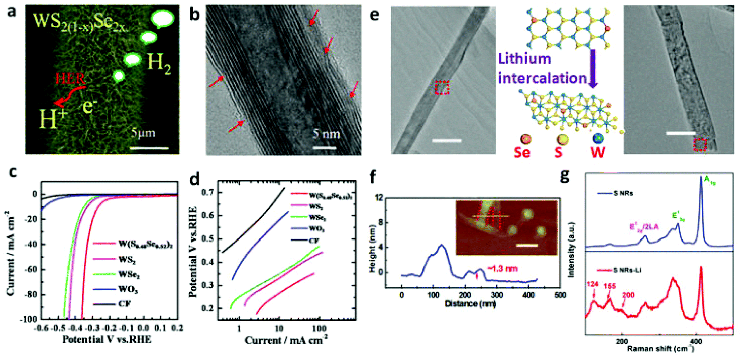
Lin et al.168 unzipped WS2 NTs to fabricate a nanoribbon (NR) morphology that insures more exposed edge sites confirmed by significantly enhanced performance for NRs with smaller overpotential of 225 mV vs. RHE at 10 mA cm−2 as compared to that of NTs (420 mV vs. RHE). From the report by Cheng et al.,167 ultrathin nanoflakes of WS2 resulted in abundant accessible edges which ultimately contributed to HER performance of approximately 100 mV of overpotential and 48 mV dec−1 of Tafel slope. Tungsten dichalcogenide based hybrid nanomaterials have also been reported to be HER active due to synergism. Yang et al.173 prepared WS2/rGO nanosheets in which the rapid electron transport gave rise to the record of overpotential ranging from 150 to 200 mV with Tafel slope of 58 mV dec−1. The compatible match of WS2 and rGO is very critical for establishing a pronounced synergism. Inspired by this, we recently174 reported self-supported and vertically aligned WS2 nanosheet on W foil sensitized by rGO for HER catalysis. The ultrathin rGO nanosheets on WS2 nanosheets contribute to the improvement of electron mobility. Significantly, the catalytic active edges of the vertical WS2 nanosheets have a direct contact with the electrolyte. These two factors efficiently improve the utilization rate of electrons, resulting in a decrease of the overpotential for HER. Meanwhile, the design of ternary dichalcogenides can realize the versatile change in their electronic structure and band gap. The recently reported results29,112,175 indicate the great potential for industry scale catalysts applications of the ternary tungsten dichalcogenides. In this respect, our group have controllably synthesized ternary WS2(1−x)Se2x NTs29 from WO3 nanowire precursors on carbon fiber substrate (Fig. 4a–c and 8a). The sulfurization and selenization process led to dislocations and defects which is apparent from Fig. 8b, acting as active sites, on the nanotubes’ walls. There, we clearly demonstrated how ternary TMDs are superior as HER catalysts as compared to the binary ones. Fig. 8c and d shows the result of HER measurement where it is evident that neither WS2 nor WSe2 NTs are as efficient as the ternary WS2(1−x)Se2x NTs. The low Tafel slopes recorded considerably evidence the fast HER rate at moderately increased overpotential. However, the confined number of the exposed edge sites on the NTs hinder the electrocatalytic activity of WS2(1−x)Se2x. Following this result, we unzipped these NTs into nanoribbons (NRs) with 2H phase to increase the number of active sites.172 Likewise, the ternary system made through incorporation of another metal atom was also found to lead to substantial improvement in the catalytic activity. Catalytic dehydrogenation and hydrodesulfurization of organic compounds by TMDs176,177 were improved upon incorporation of VIII metal atoms (Ni or Co). Inspired by this, Sobczynski et al.178 studied the catalytic hydrogen evolution reaction of Ni-doped WS2. Nickel doping, forming mixed compounds (nickel and tungsten sulfide) on the catalyst surface, improved the catalytic hydrogen evolution properties of WS2. Also, the introduction of Ni, Co or Mo into the WS2175 alters the chemical bonding states, thereby increasing the density of active sites on the surface. Even more impressively, the WS2 nanosheets with 1T phase also facilitate hydrogen evolution with very low overpotentials.23 The high concentration of the strained metallic 1T phase is associated with enhanced electrocatalytic ability. The DFT calculations show that the tensile strain on the basal plane can significantly influence the free energy of atomic hydrogen adsorption.23 After introducing a strain value of 2.7% on the surface, a free energy equal to zero can be extrapolated. Lukowski and coworkers63 reported that the 1T-WS2 nanosheets exfoliated after lithium intercalation showed dramatically improved HER with an overpotential of 142 mV (vs. RHE) at 10 mA cm−2. Recently, our group realized the phase conversion from 2H to 1T phase of ultrathin ternary WS2(1−x)Se2x NRs by lithium intercalation reaction (Fig. 8e and f).172 As shown in Fig. 8g, the emergence of new Raman shifts at ≈124, ≈155 and ≈200 cm−1 at low frequency are associated with the phonon modes of WS2(1−x)Se2x contained in the 1T phase, which achieves the lowest overpotential of ≈0.17 V at 10 mA cm−2 and a Tafel slope of ≈68 mV dec−1.
 |
| | Fig. 8 (a) HRTEM image with many defects and dislocations indicated by red arrows in WS2(1−x)Se2x NT. (b) SEM image of ternary WS2(1−x)Se2x (x = 0.52) NTs on CFs. (c) Polarization curves (after iR correction) of WO3 NWs and WS2, WSe2 and WS2(1−x)Se2x (x = 0.52) NTs along with that corresponding to pure CFs for comparison. (d) Corresponding Tafel plots obtained from the polarization curves of pure CFs, WO3 NWs and WS2, WSe2 and WS2(1−x)Se2x (x = 0.52) NTs on CFs (reproduced with permission from ref. 29. Copyright 2014 American Chemical Society). (e) TEM images of WS2(1−x)Se2x NRs before and after lithium intercalation process (scale bar, 100 nm). (f) AFM measurement of WS2(1−x)Se2x NRs after lithium intercalation (scale bar, 200 nm). (g) Raman spectra of WS2(1−x)Se2x NRs before and after lithium intercalation (reproduced with permission from ref. 172. Copyright 2015 John Wiley & Sons, Inc.). | |
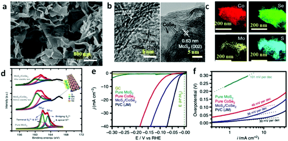 |
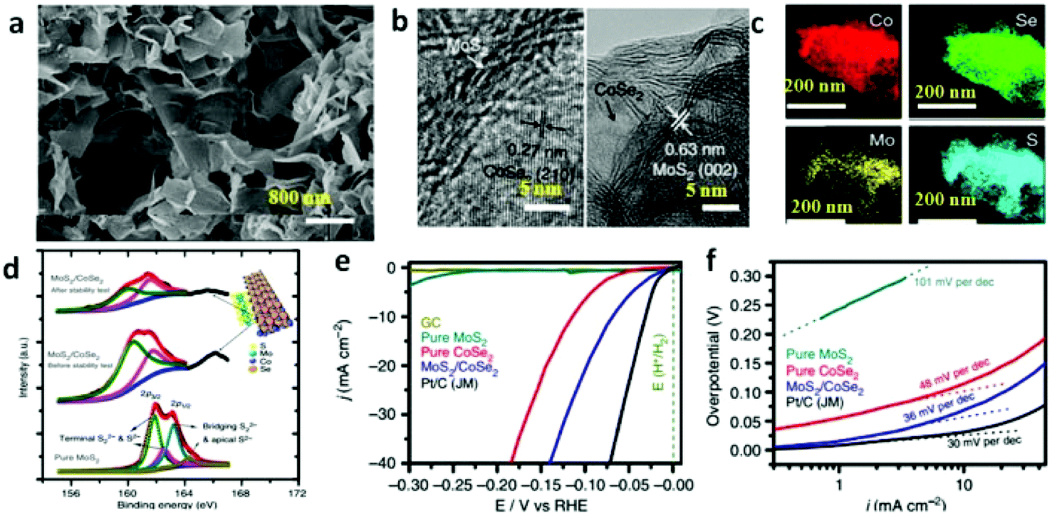
| | Fig. 9 (a) Scanning electron microscopy image of MoS2/CoSe2 hybrid. (b) HRTEM images of MoS2/CoSe2 hybrid showing distinguishable microstructures of MoS2 and CoSe2. (c) STEM-EDX elemental mapping of MoS2/CoSe2 hybrid showing clearly the homogeneous distribution of Co (red), Se (green), Mo (yellow) and S (azure). (d) S2p XPS spectra for pure MoS2, MoS2/CoSe2 hybrid and MoS2/CoSe2 hybrid after stability test. The top right corner demonstrates the structure model of MoS2/CoSe2 hybrid. (e) Polarization curves for HER on different electrocatalysts. (f) Tafel plot for the various catalysts derived from (e) (reproduced with permission from ref. 87. Copyright 2015 Macmillan Publishers Limited). | |
 |
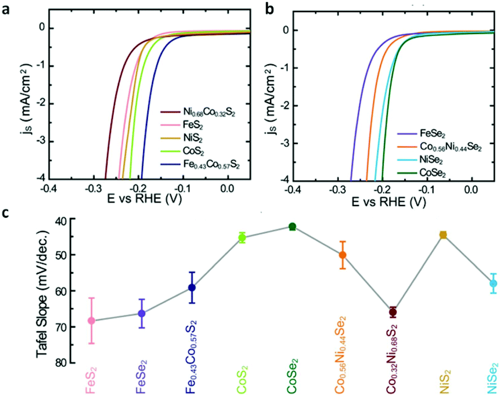
| | Fig. 10 (a) Polarization curves of transition-metal disulfides. (b) Polarization curves of transition-metal diselenides. (c) Summary of Tafel slopes of transition-metal dichalcogenide films (reproduced with permission from ref. 40. Copyright 2013 The Royal Society of Chemistry). | |
3.1.2. OER catalyzed by TMD based nanomaterials.
As a half reaction involved in water splitting and containing complex electron transfer steps, an accumulation of the energy barrier in each step leads to the sluggish kinetics of OER with large overpotential (η) to realize the oxygen evolution. Theoretically, the enthalpy of a lower to higher oxide transition, the 3d electron number of bulk transition-metal ions, the surface oxygen binding energy and Yang Shao-Horn's principle, namely eg occupancy of the surface transition-metal cations is close to unity, are the OER activity descriptors.187 Among them, the Yang Shao-Horn's principle is a recently developed criterion to evaluate the OER activity deeply. Recently, an enormous number of cobalt based compounds,18 including simple metals,188–191 metal oxides,192–196 hydro(oxy)oxides,197 phosphates,18,198–200 chalcogenides42,91 and perovskites187,201 have been designed and utilized as electrocatalysts for oxygen evolution.44 Herein, we briefly review some recent results and the state-of-the-art in cobalt diachalcodenide based OER electrocatalysts, including one-component and hybrid ones, designed in the context of performance enhancement strategies.
According to the Yang Shao-Horn's principle, cubic cobalt dichalcogenide (CoSe2) with a t2g6eg1 electronic configuration near the optimal eg filling (Fig. 11a and b) would be a terrific candidate for electrochemical water oxidation.43 Its large density of state (DOS) across the Fermi level by theoretical calculation demonstrates the metallic behavior (Fig. 11c).43 These intrinsic chemical and physical properties suggest and ensure efficient electron migration between the electrode and the surface of the catalyst for highly electrocatalytic OER performance. At the same time, the considerable active sites exposure yield also plays an important role on the superior OER performance.43 In order to further enhance the active site exposure, Liu et al. prepared atomically thick two-dimensional CoSe2 nanosheets, shown in Fig. 11d, through exfoliating the CoSe2-based inorganic–organic lamellar nanohybrids for electrocatalytic oxygen evolution.43 During the exfoliation process, a large number of Co vacancies (V′′Co, Fig. 11d and 12a), acting as active sites to catalyze the oxygen evolution reaction, formed. Compared with the bulk CoSe2 and the nanohybrids, the ultrathin CoSe2 nanosheets exhibit the best OER performance (Fig. 12b) with small overpotential (0.32 V at 10 mA cm−2) and Tafel slope (44 mV dec−1) in basic solution (0.1 M KOH). Of particular note is that DFT calculated adsorption energy of H2O molecules on the atomically thick CoSe2 is much more favorable for adsorbing H2O molecules and facilitating the mass transport (Fig. 12c). This sample lost no activity after 1000 CV cycles in 0.1 M KOH, indicating the excellent stability of the ultrathin CoSe2 nanosheets.
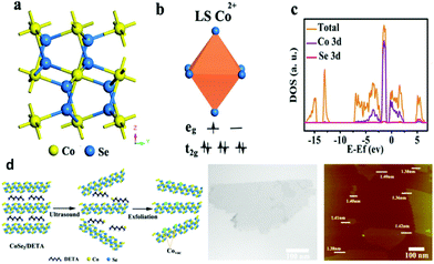 |
| | Fig. 11 (a) Crystal structure of CoSe2 in the cubic pyrite-type phase; (b) schematic spin structure of the Co cation; (c) DOS diagram for CoSe2; (d) schematic of the formation of V′′Co vacancies in CoSe2 ultrathin nanosheets (left), TEM image (middle) and AFM image (right) of the ultrathin CoSe2 nanosheet (reproduced with permission from ref. 43. Copyright 2014 American Chemical Society). | |
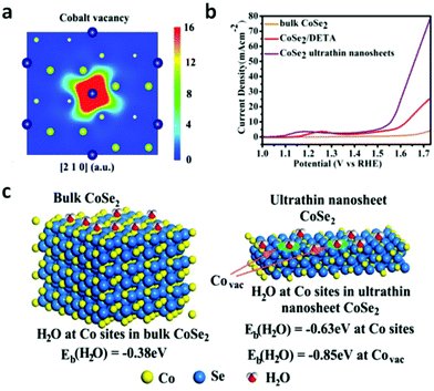 |
| | Fig. 12 (a) Schematic representations of trapped positrons of cobalt vacancies. (b) Linear sweep voltammetry (LSV) curves in 0.1 M KOH medium with bulk CoSe2, CoSe2/DETA and ultrathin CoSe2 nanosheet as the electrocatalyst. (c) First-principles study of surface H2O adsorption on different sites and performance of various materials: geometries and binding energies of H2O molecules on cobalt sites and vacancies (reproduced with permission from ref. 43. Copyright 2014 American Chemical Society). | |
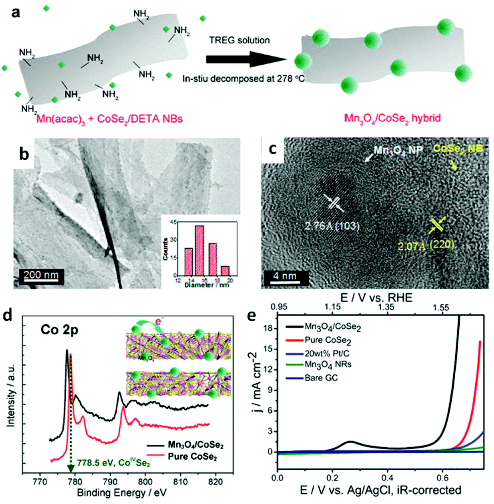
To date, abundant studies demonstrate that the OER performance of Co-based electrocatalysts can be greatly improved through incorporation of other functional materials.99,202 In this regard, the synergetic chemical coupling effects between Co-based catalysts and foreign materials presumably lead to the substantial enhancement. Thus, additional modification of the CoSe2 with other materials, such as Mn3O4 nanoparticles,42 nitrogen-doped reduced graphene44 and CeO2 nanoparticles,45 were developed for boosting its OER performance by Yu's group. They successfully prepared ultrathin lamellar mesostructured CoSe2/DETA nanobelts by solvothermal reaction. This mesostructure represents abundant and affordable material for large-scale utilization, large surface area and copious surface amino groups for anchoring the highly dispersed heteromaterials.42,98,202 As is shown in Fig. 13a–c, TEM images exhibit Mn3O4 nanoparticles with an average size of ∼15.7 nm uniformly distributed on the surface of the CoSe2 nanobelts. Bell et al. reported191 that Co cations in high oxidation states, namely CoIV, have been proposed as active centers. The CoIV species existed in CoSe2 nanobelts were believed to enhance the electrophilicity of the adsorbed O and accelerate the formation of intermediate products, such as O–OH and OOH species, to eventually generate O2 molecules.42Fig. 13d demonstrates the electron binding energy of Co2p decreased after decorating the CoSe2 by Mn3O4 nanoparticles. This phenomenon is induced by the electron transfer from Mn3O4 to CoSe2, which makes the Mn3O4 more acidic (Lewis acid). Thus, the Mn3O4 nanoparticles anchored on the CoSe2 facilitates the activation of H2O (Lewis base) molecules through Lewis acid–base interaction. As a result, the Mn3O4/CoSe2 exhibited more improved OER electrocatalytic activity than others (Fig. 13e). Analogously, the CeO2 nanoparticles, creating much more oxygen vacancies, can sensitize the CoSe2 nanobelts to form hydroperoxy species (OOHad) and further promote the OER catalytic activity. The CeO2/CoSe2 shows a small overpotential of ∼0.288 V at the current density of 10 mA cm−2, small Tafel slope of 44 mV dec−1, large anodic currents and good durability in alkaline solution.45 The chemical synergistic effect between Mo3O4 or CeO2 and CoSe2 guarantees increased OER activity relative to pure CoSe2.
 |
| | Fig. 13 (a) Polyol synthesis with CoSe2/DETA NBs to generate Mn3O4/CoSe2 hybrid. (b) TEM images of Mn3O4/CoSe2 hybrid prepared at 278 °C for 1 h. The inset in (b) shows the corresponding particle-size histogram. (c) HRTEM image of an attached nanoparticle and its neighboring CoSe2 support. (d) Co2p XPS spectra for pure CoSe2/DETA NBs and as constructed Mn3O4/CoSe2 hybrid. Inset demonstrates the electron donation from the Mn3O4 to CoSe2. Pink and yellow balls correspond to Co and Se atoms, respectively. (e) Polarization curves for OER on bare GC electrode and modified GC electrodes comprising the Mn3O4 NRs, 20 wt% Pt/C, pure CoSe2/DETA NBs and Mn3O4/CoSe2 hybrid, respectively (reproduced with permission from ref. 42. Copyright 2012 American Chemical Society). | |
Additionally, graphene sheets are becoming an inexpensively outstanding matrix to support electrocatalysts and facilitate catalytic performance through strong chemical coupling and optimized electronic structure.203,204Fig. 14a and b shows that the long belt-like CoSe2 with size of ∼2–3 μm and almost transparent features were immobilized on the N-doped reduced graphene (NG) sheet (>6 μm).44 The thickness of the CoSe2 nanobelt and NG sheet is close to ∼19.6 and ∼2.6 nm, respectively (Fig. 14c). After the electrochemical measurement in the 0.1 M KOH electrolyte, the polarization curve of NG-CoSe2 composite shows a much earlier onset potential.
 |
| | Fig. 14 (a–b) TEM images with different magnifications of NG–CoSe2 composite. The inset in (b) shows the corresponding SAED pattern. (c) AFM image and corresponding height profile of NG–CoSe2 composite. (d–e) Tafel plot and polarization curves for OER on bare GC electrode and modified GC electrodes comprising the NG sheets, commercial 20 wt% Pt/C and RuO2 catalysts, pure CoSe2 nanobelts, and NG–CoSe2 composite. (f) Schematic image demonstrates the electron donation from the NG to CoSe2. Gray, green balls and blue belts correspond to C, N atoms and CoSe2 nanobelts, respectively (reproduced with permission from ref. 44. Copyright 2014 American Chemical Society). | |
Moreover, the corresponding Tafel plots displayed in Fig. 14d exhibits the smallest Tafel slope (40 mV dec−1) for the hybrid sample, reveals that the composite outperforms other catalysts, including commercial RuO2, pure CoSe2 nanobelts, and commercial Pt/C. Importantly, the comparison of the original polarization curve and that of after 2000 cycles of NG–CoSe2 and RuO2 demonstrates the superiority and stability of the material for OER property in basic media (Fig. 14e). In this system, the largely exposed CoSe2 surfaces, tightly bound by the NG sheet, were utilized as active substance. The introduction of the NG sheets can afford high electrical conductivity and prevent undesired aggregation. From the d-band theory,187,205 the interaction between oxygen and metal d states, including the bond strength of oxygen-related intermediate species, can be optimized via modulating the d-electron filling in eg bands. Therefore, the electron donation from NG sheets to CoSe2 afford more eg-filling in CoSe2 (Fig. 14f), which could optimize the surface–oxygen interaction to moderate the bond strength, thereby greatly enhancing the OER kinetics. Meanwhile, nitrogen and sulfur co-doped graphene oxide also used to anchor the CoS2 nanoparticles for considerable OER performance.206 The electrocatalytic performance of different TMD-based electrocatalysts is summarized in Fig. 15, demonstrating the practically potential application although the real understanding of the contribution of cobalt dichalcogenide framework for the observed catalytic activity needs further investigation and confirmation. It is noteworthy that due to the likely chemical instability of common metal dichalcogenides in the oxidative and basic conditions, the stability of these MX2-based electrocatalysts for OER needs to be carefully studied and verified.
 |
| | Fig. 15 OER performance comparison of different TMD based electrocatalysts with RuO2 (data gathered from ref. 42–45 and 206). | |
3.2. Photochemical water splitting
Photocatalytic water splitting, using solar energy to produce H2, is considered as a promising technology to address environmental crises and energy shortages.207–212 Solar water splitting based on inorganic semiconductors as a means of converting solar energy to chemical energy in the form of fuels has been drawn much attention since the 1970s.208,213 Typically, the photocatalytic ability of a semiconductor depends on the absolute positions of the valence band (EVB) and conduction band (ECB) edges. If its ECB is located more negative than that of hydrogen (EH2/H+) and the EVB is more positive than that of oxygen (EO2/H2O), it is possible to split the water molecule into H2 and O2 under light. A proper band gap is therefore of primary importance for photocatalytic reactions.208 Furthermore, the composite photocatalysts, including hybrids with other semiconductors, carbon materials and noble metals, are extensively studied due to improved carrier diffusion and efficient absorption of the solar spectrum.8,214 TMDs, especially Mo and W based ones, have been used as photoelectrodes for water splitting due to the following advantages:215,216 (i) their band gaps ranges from 1.0 to 1.6 eV, which are well matched with the solar spectrum. (ii) These semiconductors should be quite stable towards to photodissolution because of d–d optical transitions and involving nonbonding electrons. For example, the stability of the MoS2 photoelectrode has been associated with the fact that the electronic excitation does not involve a transition having S2− → Mo(IV) charge-transfer character. (iii) They are earth-abundant and composed of non-precious materials. However, TMD nanostructures are usually utilized as cocatalysts for photocatalytic H2 generation, presently, because their conduction band position is inadaptable to reduce H+ to H2 under light illumination. In this section, we summarize the photocatalytic properties of both single component and composite TMD based on very commonly used MoS2 and WS2 materials. In particular, monolayer MoS2 and the heterostructures, in which MoS2 and WS2 act as cocatalysts, are highlighted.
3.2.1. Monolayer MoS2 and its photocatalytic properties.
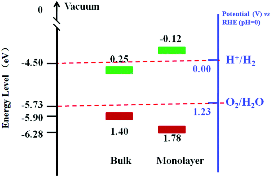
The optical absorption spectrum of MoS2 nanomaterials has been calculated and thoroughly studied experimentally.32,218,219 DFT calculations and experimental results show that the band gap of MoS2 would be increased dramatically when the sample thickness is reduced from a few layers to an ideal monolayer.32,220,221 The direct gap of monolayer MoS2 is about 1.9 eV, which is larger than that of bulk MoS2 (1.29 eV).32,222,223 Notably, the increased band gap of the MoS2 leads to a change in the redox potential and improves the photocatalytic property. Fig. 16 presents the energy diagrams of the VB and CB edge potentials in bulk and monolayer MoS2.217 It is found that the bulk MoS2 can oxidize H2O to produce O2 but can not reduce H+ to H2. In contrast, the monolayer MoS2 can oxidize H2O more efficiently than bulk MoS2. The CB edge position of the monolayer MoS2 is more negative than that of H+/H2, suggesting its photocatalytic potential to reduce H+ for H2. However, the research on the direct use of MoS2 as photocatalyst is rarely reported due to the low-yield production of monolayer MoS2 nanosheets.224
 |
| | Fig. 16 Energy diagrams of the VB and CB edge potentials in bulk and monolayer MoS2 (data gathered from ref. 217). | |
3.2.2. TMDs as cocatalysts for photocatalytic water splitting.
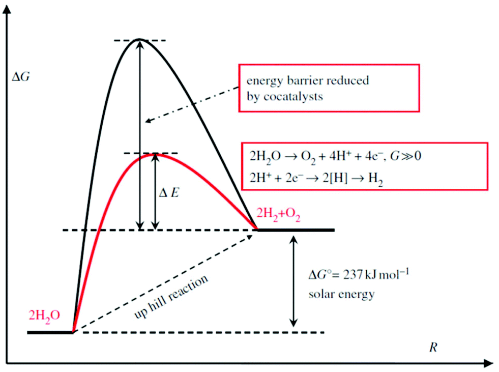
As a thermodynamically uphill reaction, water splitting is a non-spontaneous process. Thus, some cocatalysts usually are loaded on the semiconductors that act as photo-harvesters to reduce the energy barrier (Scheme 1). At the same time, the cocatalyst is capable of assisting in photo-generated electron–hole separation and suppressing the photo-corrosion to increase the stability of semiconductor photocatalysts.49 To date, many TMDs, i.e. MoS2,50–52,225–227 WS253,214 and NiS2,228 have been reported as excellent candidates for cost-effective cocatalysts.
 |
| | Scheme 1 Schematic description of energy diagram for photocatalytic water splitting (reproduced with permission from ref. 212. Copyright 2013 Royal Society). | |
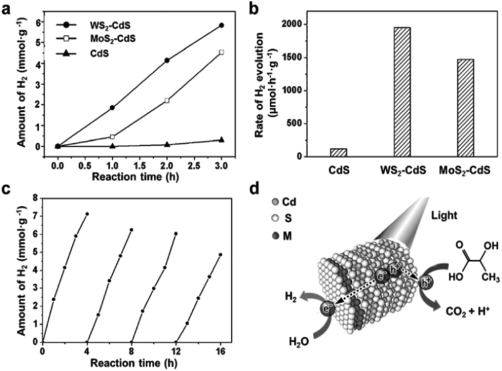
Due to its high mobility for charge transport, MoS2 nanostructure as a cocatalyst can enhance the separation of photo-excited electrons and holes as well as decrease the activation potentials for H2 evolution, which is paramount for developing photocatalytic water splitting activity of photocatalysts. For instance, TiO2, as a typical UV light driven photocatalyst, has been reported to show enhanced photocatalytic H2 production activity by loading MoS2 nanostructures.225,230–233 In order to improve interfacial charge transfer, Xiang's group226 reported a TiO2/MoS2/graphene composite demonstrating a 7-times H2 production rate improvement than that obtained from TiO2 alone under UV irradiation. Besides, as is known to us, single component visible light driven photocatalysts face the limitation of photoelectric conversion efficiency and low photocatalytic activity.8,234–236 Nowadays, therefore various visible light driven photocatalysts, such as CdS,237 Zn0.2Cd0.8S,238 CdSe,227 have been studied in combination with TMDs to obtain higher photocatalytic efficiency. Zong et al.237 reported enhancement of the photocatalytic H2 production activity of an MoS2–CdS compound. Subsequently, Zhang's group229 employed a facile one-pot wet-chemical method to fabricate MoS2–CdS and WS2–CdS nanohybrids. They found that the single-layered MoS2/WS2 selectively grew on the Cd-rich (0001) surface of wurtzite CdS nanocrystals, wherein the strong interaction with S layer of MoS2/WS2 occurred. This kind of nanohybrids reduces charge carrier recombination and photocorrosion of CdS, leading to excellent photocatalytic activity with good stability. As shown in Fig. 17, they achieved a hydrogen evolution rate of 1472 μmol h−1 g−1 with MoS2–CdS nanohybrids, which is 12 times higher than that of pure CdS nanocrystals, and this photocatalyst still remained catalytically active in 16 h irradiation under visible light. To get better photocatalytic H2 production activity, Yang et al.51 introduced metal nanoparticles (Cr, Ag) to the surface of MoS2 nanosheets by a simple solution method and then loaded onto a CdS catalyst. With this metal-MoS2 heterostructure, the recombination of photogenerated carriers in MoS2 nanosheets was reduced, leading to a great enhancement of photoelectric conversion efficiency. As a result, they attained an average rate of 38000 μmol h−1 g−1 H2 evolution under visible light irradiation with Cr–MoS2 hybrid as the cocatalyst.51 Furthermore, Chang and coworkers composited MoS2 nanosheets with graphene to anchor on CdS nanocrystals and achieved a 1.8 mmol h−1 H2 evolution rate, which is much higher than that of CdS combined with noble metal Pt, in lactic acid solution under visible light.50 As environmental friendly and noble metal free photocatalysts, some carbon based materials have also been used for water splitting with MoS2 as cocatalyst.52,239 For example, Hou et al.52 fabricated graphitic carbon nitride and MoS2 layered nanojunctions to catalyze water for hydrogen evolution under visible light. They found that the 0.5 wt% MoS2/mpg-CN (mesoporous g-CN) performs better than 0.5 wt% Pt/mpg-CN with visible light irradiation. These results obviously suggest that MoS2 can be utilized to improve the poor hydrogen evolution kinetics of mpg-CN nanomaterial. Similar to MoS2, other TMDs such as WS2 and NiS2 also display a crucial role as cocatalyst in photocatalytic water splitting. Zong et al.53 reported that the H2 generation rate of CdS is increased by up to 28 times with WS2 as a good cocatalyst under visible light and also exhibits a persistently high H2-production capability in lactic acid solution. As such, ternary CdLa2S4 with 2 wt% NiS2 loading was also reported by Xue's group228 as exhibiting a H2 production rate of 2.5 mmol h−1 g−1, which was 3 times higher than that of the pristine CdLa2S4 photocatalyst. This was attributed to the enhanced separation of photogenerated electrons and holes as well as the activation effect of NiS2. The performance comparison of different photocatalysts with TMDs as cocatalyst for water splitting reported hitherto is demonstrated in Table 3. Moreover, owing to the feature of excellent electrocatalytic activity of layered TMDs, they are also utilized in the photoelectrochemical system for hydrogen generation. For example, MoS2 was employed as an electrocatalyst in the photocathode coupled by silicon nanowires.240,241 The dramatically enhanced current density along with significant anodic shift of onset potential suggested the highly active photoelectrochemical property for HER after preparation of the hybrid. Further, metallic MoS2 was integrated with p-Si to act as photocathode electrode, revealing high photocurrent density of 17.6 mA cm−2 at 0 V vs. RHE.242
 |
| | Fig. 17 Photocatalytic activity of MS2–CdS nanohybrids for hydrogen evolution reaction. (a) Time-dependent photocatalytic H2 evolution for WS2–CdS, MoS2–CdS and pure CdS; (b) comparison of the H2 evolution rate under visible light irritation for WS2–CdS, MoS2–CdS and pure CdS; (c) cycling test of photocatalytic H2 evolution for WS2–CdS; (d) schematic illustration of the photocatalytic process of MS2–CdS nanohybrids in lactic acid solution (reproduced with permission from ref. 229. Copyright 2015 John Wiley & Sons, Inc.). | |
Table 3 Comparison of different photocatalysts with TMDs as cocatalyst for water splitting
| Cocatalyst |
Photocatalyst |
Loading method |
Light source |
Reaction solution |
Activity (μmol h−1 g−1) |
Quantum efficiency (%) |
Stability |
Ref. |
| MoS2 |
TiO2 |
Hydrothermal |
UV-Vis |
Methanol |
2000-MoS2(1T) |
|
|
111
|
|
|
|
|
|
250-MoS2(2H) |
|
|
|
| TiO2/RGO |
Hydrothermal |
UV-Vis |
Ethanol |
2066 |
9.7 (365 nm) |
>12 h |
226
|
| g-C3N4 |
Impregnation–sulfidation |
λ ≥ 420 nm |
Lactic acid |
1030 |
2.1 (420 nm) |
<16 h |
52
|
| CdS |
Impregnation–sulfidation |
λ ≥ 420 nm |
Na2S, Na2SO3 |
5400 |
|
|
237
|
| Cr/CdS |
Hydrothermal method |
λ ≥ 420 nm |
Na2S, Na2SO3 |
38000 |
|
>12 h |
51
|
| G-CdS |
Hydrothermal method |
λ ≥ 420 nm |
Lactic acid |
18000 |
28.1 (420 nm) |
>25 h |
50
|
| CdSe |
Dispersion–adsorption |
λ ≥ 400 nm |
Na2S, Na2SO3 |
890 |
|
>5 h |
227
|
| Zn0.2Cd0.8S |
In situ photo-assisted deposition |
λ ≥ 420 nm |
Na2S, Na2SO3 |
420 |
|
>18 h |
238
|
| WS2 |
CdS |
Impregnation–sulfidation |
λ ≥ 420 nm |
Lactic acid |
4200 |
5 (420 nm) |
<15 h |
53
|
| NiS2 |
CdLa2S4 |
Hydrothermal method |
λ ≥ 420 nm |
Na2S, Na2SO3 |
2500 |
1.6 (420 nm) |
>20 h |
228
|
3.3. Surface plasmon resonance (SPR) enhanced water splitting
Surface plasmon resonance (SPR) results from the collective oscillation of the conduction electrons of plasmonic-metal, i.e. Au, Ag and Cu, nanoparticles. These surface plasmons predominantly relax non-radiatively via Landau damping, yielding highly energetic “hot” electrons emerging on the surface.243,244 When plasmonic-metal nanoparticles are proximal to a semiconductor, a plasmon-mediated electron transfer process will happen and boost the photocatalytic performance.244–246 Fang's group247 has reported that the plasmon-excited “hot” electrons can be injected into the MoS2 layer due to the low Schottky barrier between MoS2 and Au metal. In this situation, the MoS2 monolayers become acceptors of the “hot” electrons. Very recently, Shi et al.248 confirmed that these hot electrons transferred from Au nanorod are suitable to facilitate the HER performance in the acid solution of MoS2 nanosheets (Fig. 18a and d). The overpotential and Tafel slope shown in Fig. 18b are reduced with 808 nm laser irradiation. The i–t curves (Fig. 18c) indicate the good reversibility of this process. It is worth pointing out that the phase conversion from 2H to 1T induced by SPR also plays a crucial role in promoting the electrocatalytic property.249 Yin et al.250 found that the generated local electric field around Au nanoparticles promotes the photogenerated electron–hole separation in the MoS2 nanosheets. This phenomenon was suggested to enhance the photocatalytic water splitting in the photoelectrochemical cell using Au–MoS2 composite.
 |
| | Fig. 18 (a) Schematic Au–MoS2 and energy level diagram illuminating hot electrons injection and change of MoS2 Fermi level. (b) HER polarization curves obtained on several catalysts as indicated. (c) i–t curves with and without 808 nm laser excitation. (d) The Tafel plots of Au rod (green), ce-MoS2 (blue), Au–MoS2 (black) and Au–MoS2 (808) (red) derived from the early stages of HER polarization curves (reproduced with permission from ref. 248. Copyright 2015 American Chemical Society). | |
4. Conclusion and perspectives
Capturing energy from the sun and/or water provides a greener approach to emerge from the damaging fossil fuel era. Being emerging candidates for water splitting, TMD based nanomaterials are extensively studied as electrocatalysts and photocatalysts for hydrogen and oxygen production. This review provides a survey of literatures for the preparation and applications of various TMD materials in electrocatalytic and photocatalytic water splitting. Methods such as chemical exfoliation, solvothermal and chemical vapor deposition have been utilized, with modifications thereof, encompassing top-down and bottom-up approaches to synthesize high quality TMDs intended for water splitting. The morphology through which maximum active sites are exposed, synergism from the individual components in the hybrid structure and a 1T phase of MoS2 and WS2 were directives reported so far for enhanced electrocatalytic HER or OER. More importantly, it is imperative to further consider Co-based dichalcogenides as potential materials in both HER and OER. Due to their unique electronic configuration near the optimal eg filling, electrodes built on the basis of Co dichalcogenides demonstrate excellent performance without the need of phase transfer. As one of the prospects, successful incorporation of heteroatoms into the lattice of other TMDs is speculated to greatly improve the electrocatalytic water splitting performance via modulating the electronic structure. Of particular note is that the monolayered TMDs are potential candidates for photocatalytic water splitting under visible light (Fig. 19), rendering the opportunity to harvest solar light for photocatalytic hydrogen or oxygen evolution (except for some metallic ones: labeled in red). Additionally, the SPR effect is also effectively employed to boost electro- or photo-catalytic water splitting performance. Some other hybrid nanostructures composited with carbon materials, semiconductors and metals have also exhibited great promise for overcoming some of the limitations of TMDs.
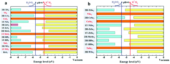 |
| | Fig. 19 Band edge positions of monolayer (a) sulfide and (b) selenide TMDs relative to the vacuum level, including the redox potentials for H+/H2 and O2/H2O at pH = 0. The band edge data are compiled from ref. 48 and 251–254. | |
A future direction, therefore, also lies in the design of novel TMD based nanomaterials aimed to exploit their new functionalities for efficient water splitting.
Acknowledgements
This work was supported by the National Natural Science Foundation of China (No. 21373065 and 61474033), 973 Program of the Ministry of Science and Technology of China (No. 2012CB934103), Beijing Natural Science Foundation (No. 2144059) and CAS Key Laboratory of Nanosystem and Hierarchical Fabrication. The authors gratefully acknowledge the support of K. C. Wong Education Foundation.
Notes and references
- T. Hisatomi, J. Kubota and K. Domen, Chem. Soc. Rev., 2014, 43, 7520–7535 RSC
 .
.
- M. R. Gholipour, C. T. Dinh, F. Béland and T. O. Do, Nanoscale, 2015, 7, 8187–8208 RSC .
- J. M. Bockris, Int. J. Hydrogen Energy, 2002, 27, 731–740 CrossRef CAS .
- J. R. Rostrup-Nielsen, Catal. Rev. Sci. Eng., 2004, 46, 247–270 CAS .
- J. Greeley, T. F. Jaramillo, J. Bonde, I. Chorkendorff and J. K. Norskov, Nat. Mater., 2006, 5, 909–913 CrossRef CAS PubMed .
- M. Chhowalla, H. S. Shin, G. Eda, L.-J. Li, K. P. Loh and H. Zhang, Nat. Chem., 2013, 5, 263–275 CrossRef PubMed .
- C. Wang, Q. Hu, J. Huang, C. Zhu, Z. Deng, H. Shi, L. Wu, Z. Liu and Y. Cao, Appl. Surf. Sci., 2014, 292, 161–164 CrossRef CAS .
- Y. Wang, Q. Wang, X. Zhan, F. Wang, M. Safdar and J. He, Nanoscale, 2013, 5, 8326–8339 RSC .
- T. Sun, E. Liu, X. Liang, X. Hu and J. Fan, Appl. Surf. Sci., 2015, 347, 696–705 CrossRef CAS .
- X. Fan, J. Wan, E. Liu, L. Sun, Y. Hu, H. Li, X. Hu and J. Fan, Ceram. Int., 2015, 41, 5107–5116 CrossRef CAS .
- M.-S. Park and M. Kang, Mater. Lett., 2008, 62, 183–187 CrossRef CAS .
- C. G. Morales-Guio, L.-A. Stern and X. Hu, Chem. Soc. Rev., 2014, 43, 6555–6569 RSC .
- M. Grätzel, Nature, 2001, 414, 338–344 CrossRef PubMed .
- Y. Sun, S. Gao, F. Lei and Y. Xie, Chem. Soc. Rev., 2015, 44, 623–636 RSC .
- Y. Sun, Z. Sun, S. Gao, H. Cheng, Q. Liu, J. Piao, T. Yao, C. Wu, S. Hu and S. Wei, Nat. Commun., 2012, 3, 1057 CrossRef PubMed .
- F. Lei, Y. Sun, K. Liu, S. Gao, L. Liang, B. Pan and Y. Xie, J. Am. Chem. Soc., 2014, 136, 6826–6829 CrossRef CAS PubMed .
- R. De Levie, J. Electroanal. Chem., 1999, 476, 92–93 CrossRef CAS .
- S. Cobo, J. Heidkamp, P.-A. Jacques, J. Fize, V. Fourmond, L. Guetaz, B. Jousselme, V. Ivanova, H. Dau and S. Palacin, Nat. Mater., 2012, 11, 802–807 CrossRef CAS PubMed .
- C. C. McCrory, S. Jung, I. M. Ferrer, S. M. Chatman, J. C. Peters and T. F. Jaramillo, J. Am. Chem. Soc., 2015, 137, 4347–4357 CrossRef CAS PubMed .
- V. Nicolosi, M. Chhowalla, M. G. Kanatzidis, M. S. Strano and J. N. Coleman, Science, 2013, 340, 1226419 CrossRef .
- L. Yang, H. Hong, Q. Fu, Y. Huang, J. Zhang, X. Cui, Z. Fan, K. Liu and B. Xiang, ACS Nano, 2015, 9, 6478–6483 CrossRef CAS PubMed .
- M. R. Gao, M. K. Chan and Y. Sun, Nat. Commun., 2015, 6, 7493 CrossRef PubMed .
- D. Voiry, H. Yamaguchi, J. Li, R. Silva, D. C. Alves, T. Fujita, M. Chen, T. Asefa, V. B. Shenoy and G. Eda, Nat. Mater., 2013, 12, 850–855 CrossRef CAS PubMed .
- X. Huang, Z. Zeng and H. Zhang, Chem. Soc. Rev., 2013, 42, 1934–1946 RSC .
- M. S. Faber and S. Jin, Energy Environ. Sci., 2014, 7, 3519–3542 CAS .
- M. Zeng and Y. Li, J. Mater. Chem. A, 2015, 3, 14942–14962 CAS .
- P. C. Vesborg, B. Seger and I. Chorkendorff, J. Phys. Chem. Lett., 2015, 6, 951–957 CrossRef CAS PubMed .
- R. Kappera, D. Voiry, S. E. Yalcin, B. Branch, G. Gupta, A. D. Mohite and M. Chhowalla, Nat. Mater., 2014, 13, 1128–1134 CrossRef CAS PubMed .
- K. Xu, F. Wang, Z. Wang, X. Zhan, Q. Wang, Z. Cheng, M. Safdar and J. He, ACS Nano, 2014, 8, 8468–8476 CrossRef CAS PubMed .
- K. Xu, Z. Wang, X. Du, M. Safdar, C. Jiang and J. He, Nanotechnology, 2013, 24, 465705 CrossRef PubMed .
- Q. H. Wang, K. Kalantar-Zadeh, A. Kis, J. N. Coleman and M. S. Strano, Nat. Nanotechnol., 2012, 7, 699–712 CrossRef CAS PubMed .
- K. F. Mak, C. Lee, J. Hone, J. Shan and T. F. Heinz, Phys. Rev. Lett., 2010, 105, 136805 CrossRef PubMed .
- F. Wang, Z. Wang, Q. Wang, F. M. Wang, L. Yin, K. Xu, Y. Huang and J. He, Nanotechnology, 2015, 26, 292001 CrossRef PubMed .
- B. Peng, P. K. Ang and K. P. Loh, Nano Today, 2015, 10, 128–137 CrossRef CAS .
- B. Hinnemann, P. G. Moses, J. Bonde, K. P. Jørgensen, J. H. Nielsen, S. Horch, I. Chorkendorff and J. K. Nørskov, J. Am. Chem. Soc., 2005, 127, 5308–5309 CrossRef CAS PubMed .
- T. F. Jaramillo, K. P. Jørgensen, J. Bonde, J. H. Nielsen, S. Horch and I. Chorkendorff, Science, 2007, 317, 100–102 CrossRef CAS PubMed .
- Y. Feng, T. He and N. Alonso-Vante, Electrochim. Acta, 2009, 54, 5252–5256 CrossRef CAS .
- D. Susac, L. Zhu, M. Teo, A. Sode, K. Wong, P. Wong, R. Parsons, D. Bizzotto, K. Mitchell and S. Campbell, J. Phys. Chem. C, 2007, 111, 18715–18723 CAS .
- L. Zhu, M. Teo, P. Wong, K. Wong, I. Narita, F. Ernst, K. Mitchell and S. Campbell, Appl. Catal., A, 2010, 386, 157–165 CrossRef CAS .
- D. Kong, J. J. Cha, H. Wang, H. R. Lee and Y. Cui, Energy Environ. Sci., 2013, 6, 3553–3558 CAS .
- D. Kong, H. Wang, Z. Lu and Y. Cui, J. Am. Chem. Soc., 2014, 136, 4897–4900 CrossRef CAS PubMed .
- M.-R. Gao, Y.-F. Xu, J. Jiang, Y.-R. Zheng and S.-H. Yu, J. Am. Chem. Soc., 2012, 134, 2930–2933 CrossRef CAS PubMed .
- Y. Liu, H. Cheng, M. Lyu, S. Fan, Q. Liu, W. Zhang, Y. Zhi, C. Wang, C. Xiao, S. Wei, B. Ye and Y. Xie, J. Am. Chem. Soc., 2014, 136, 15670–15675 CrossRef CAS PubMed .
- M. R. Gao, X. Cao, Q. Gao, Y. F. Xu, Y.-R. Zheng, J. Jiang and S. H. Yu, ACS Nano, 2014, 8, 3970–3978 CrossRef CAS PubMed .
- Y. R. Zheng, M. R. Gao, Q. Gao, H. H. Li, J. Xu, Z. Y. Wu and S. H. Yu, Small, 2015, 11, 182–188 CrossRef CAS PubMed .
- F. A. Rasmussen and K. S. Thygesen, J. Phys. Chem. C, 2015, 119, 13169–13183 CAS .
- H. Jiang, J. Phys. Chem. C, 2012, 116, 7664–7671 CAS .
- H. L. Zhuang and R. G. Hennig, J. Phys. Chem. C, 2013, 117, 20440–20445 CAS .
- J. Ran, J. Zhang, J. Yu, M. Jaroniec and S. Z. Qiao, Chem. Soc. Rev., 2014, 43, 7787–7812 RSC .
- K. Chang, Z. Mei, T. Wang, Q. Kang, S. Ouyang and J. Ye, ACS Nano, 2014, 8, 7078–7087 CrossRef CAS PubMed .
- L. Yang, D. Zhong, J. Zhang, Z. Yan, S. Ge, P. Du, J. Jiang, D. Sun, X. Wu and Z. Fan, ACS Nano, 2014, 8, 6979–6985 CrossRef CAS PubMed .
- Y. Hou, A. B. Laursen, J. Zhang, G. Zhang, Y. Zhu, X. Wang, S. Dahl and I. Chorkendorff, Angew. Chem., Int. Ed., 2013, 52, 3621–3625 CrossRef CAS PubMed .
- X. Zong, J. Han, G. Ma, H. Yan, G. Wu and C. Li, J. Phys. Chem. C, 2011, 115, 12202–12208 CAS .
- H. W. Kroto, J. R. Heath, S. C. O'Brien, R. F. Curl and R. E. Smalley, Nature, 1985, 318, 162–163 CrossRef CAS .
- A. K. Geim, Science, 2009, 324, 1530–1534 CrossRef CAS PubMed .
- C. Rao and A. Nag, Eur. J. Inorg. Chem., 2010, 4244–4250 CrossRef CAS .
- H.-L. Tsai, J. Heising, J. L. Schindler, C. R. Kannewurf and M. G. Kanatzidis, Chem. Mater., 1997, 9, 879–882 CrossRef CAS .
- K. Novoselov, D. Jiang, F. Schedin, T. Booth, V. Khotkevich, S. Morozov and A. Geim, Proc. Natl. Acad. Sci. U. S. A., 2005, 102, 10451–10453 CrossRef CAS PubMed .
- R. Tenne, J. Mater. Res., 2006, 21, 2726–2743 CrossRef CAS .
- J. N. Coleman, M. Lotya, A. O'Neill, S. D. Bergin, P. J. King, U. Khan, K. Young, A. Gaucher, S. De and R. J. Smith, Science, 2011, 331, 568–571K CrossRef CAS PubMed .
- G. Cunningham, M. Lotya, C. S. Cucinotta, S. Sanvito, S. D. Bergin, R. Menzel, M. S. Shaffer and J. N. Coleman, ACS Nano, 2012, 6, 3468–3480 CrossRef CAS PubMed .
- K. G. Zhou, N. N. Mao, H. X. Wang, Y. Peng and H. L. Zhang, Angew. Chem., Int. Ed., 2011, 50, 10839–10842 CrossRef CAS PubMed .
- M. A. Lukowski, A. S. Daniel, C. R. English, F. Meng, A. Forticaux, R. J. Hamers and S. Jin, Energy Environ. Sci., 2014, 7, 2608–2613 CAS .
- J. N. Coleman, Adv. Funct. Mater., 2009, 19, 3680–3695 CrossRef CAS .
-
C. M. Hansen, Hansen solubility parameters: a user's handbook, CRC Press, 2007 Search PubMed .
- H. Ramakrishna Matte, A. Gomathi, A. K. Manna, D. J. Late, R. Datta, S. K. Pati and C. Rao, Angew. Chem., 2010, 122, 4153–4156 CrossRef .
- A. Ambrosi, Z. Sofer and M. Pumera, Chem. Commun., 2015, 51, 8450–8453 RSC .
- M. A. Lukowski, A. S. Daniel, F. Meng, A. Forticaux, L. Li and S. Jin, J. Am. Chem. Soc., 2013, 135, 10274–10277 CrossRef CAS PubMed .
- H. Wang, Z. Lu, S. Xu, D. Kong, J. J. Cha, G. Zheng, P.-C. Hsu, K. Yan, D. Bradshaw and F. B. Prinz, Proc. Natl. Acad. Sci. U. S. A., 2013, 110, 19701–19706 CrossRef CAS PubMed .
- D. Voiry, M. Salehi, R. Silva, T. Fujita, M. Chen, T. Asefa, V. B. Shenoy, G. Eda and M. Chhowalla, Nano Lett., 2013, 13, 6222–6227 CrossRef CAS PubMed .
- G. Eda, H. Yamaguchi, D. Voiry, T. Fujita, M. Chen and M. Chhowalla, Nano Lett., 2011, 11, 5111–5116 CrossRef CAS PubMed .
- Z. Zeng, T. Sun, J. Zhu, X. Huang, Z. Yin, G. Lu, Z. Fan, Q. Yan, H. H. Hng and H. Zhang, Angew. Chem., Int. Ed., 2012, 51, 9052–9056 CrossRef CAS PubMed .
- Z. Zeng, Z. Yin, X. Huang, H. Li, Q. He, G. Lu, F. Boey and H. Zhang, Angew. Chem., Int. Ed., 2011, 50, 11093–11097 CrossRef CAS PubMed .
- J.-H. Chen, C. Jang, S. Adam, M. Fuhrer, E. Williams and M. Ishigami, Nat. Phys., 2008, 4, 377–381 CrossRef CAS .
- G. Demazeau, J. Mater. Chem., 1999, 9, 15–18 RSC .
- M. S. Whittingham, Curr. Opin. Solid State Mater. Sci., 1996, 1, 227–232 CrossRef CAS .
- M. K. Devaraju and I. Honma, Adv. Energy Mater., 2012, 2, 284–297 CrossRef CAS .
- D. Wang, Z. Pan, Z. Wu, Z. Wang and Z. Liu, J. Power Sources, 2014, 264, 229–234 CrossRef CAS .
- X. J. Lv, G. W. She, S. X. Zhou and Y. M. Li, RSC Adv., 2013, 3, 21231–21236 RSC .
- S. J. Bao, C. M. Li, C.-X. Guo and Y. Qiao, J. Power Sources, 2008, 180, 676–681 CrossRef CAS .
- X. Ren, L. Pang, Y. Zhang, X. Ren, H. Fan and S. F. Liu, J. Mater. Chem. A, 2015, 3, 10693–10697 CAS .
- Y. Xu, C. Zheng, S. Wang and Y. Hou, Electrochim. Acta, 2015, 174, 653–659 CrossRef CAS .
- J. Li, X. Zhou, Z. Xia, Z. Zhang, J. Li, Y. Ma and Y. Qu, J. Mater. Chem. A, 2015, 3, 13066–13071 CAS .
- H. Yu, X. Yu, Y. Chen, S. Zhang, P. Gao and C. Li, Nanoscale, 2015, 7, 8731–8738 RSC .
- D. Hou, W. Zhou, X. Liu, K. Zhou, J. Xie, G. Li and S. Chen, Electrochim. Acta, 2015, 166, 26–31 CrossRef CAS .
- B. Mahler, V. Hoepfner, K. Liao and G. A. Ozin, J. Am. Chem. Soc., 2014, 136, 14121–14127 CrossRef CAS PubMed .
- M.-R. Gao, J.-X. Liang, Y.-R. Zheng, Y.-F. Xu, J. Jiang, Q. Gao, J. Li and S.-H. Yu, Nat. Commun., 2015, 6, 5982 CrossRef CAS PubMed .
- W. Zhou, K. Zhou, D. Hou, X. Liu, G. Li, Y. Sang, H. Liu, L. Li and S. Chen, ACS Appl. Mater. Interfaces, 2014, 6, 21534–21540 CAS .
- Q. Liu, J. Shi, J. Hu, A. M. Asiri, Y. Luo and X. Sun, ACS Appl. Mater. Interfaces, 2015, 7, 3877–3881 CAS .
- H. Liang, L. Li, F. Meng, L. Dang, J. Zhuo, A. Forticaux, Z. Wang and S. Jin, Chem. Mater., 2015, 27, 5702–5711 CrossRef CAS .
- M. R. Gao, Y. F. Xu, J. Jiang and S. H. Yu, Chem. Soc. Rev., 2013, 42, 2986–3017 RSC .
- Y. Qian, Adv. Mater., 1999, 11, 1101–1102 CrossRef CAS .
- W. MingáLau, J. Mater. Chem., 2005, 15, 4555–4559 RSC .
- S. Xu, Z. Lei and P. Wu, J. Mater. Chem. A, 2015, 3, 16337–16347 CAS .
- T. N. Ye, L.-B. Lv, M. Xu, B. Zhang, K. X. Wang, J. Su, X. H. Li and J.-S. Chen, Nano Energy, 2015, 15, 335–342 CrossRef CAS .
- Y. Li, H. Wang, L. Xie, Y. Liang, G. Hong and H. Dai, J. Am. Chem. Soc., 2011, 133, 7296–7299 CrossRef CAS PubMed .
- L. Liao, J. Zhu, X. Bian, L. Zhu, M. D. Scanlon, H. H. Girault and B. Liu, Adv. Funct. Mater., 2013, 23, 5326–5333 CrossRef CAS .
- M. R. Gao, W. T. Yao, H.-B. Yao and S. H. Yu, J. Am. Chem. Soc., 2009, 131, 7486–7487 CrossRef CAS PubMed .
- Y. F. Xu, M. R. Gao, Y. R. Zheng, J. Jiang and S. H. Yu, Angew. Chem., Int. Ed., 2013, 52, 8546–8550 CrossRef CAS PubMed .
- D. Kong, H. Wang, J. J. Cha, M. Pasta, K. J. Koski, J. Yao and Y. Cui, Nano Lett., 2013, 13, 1341–1347 CrossRef CAS PubMed .
- Y. Zhang, Q. Ji, G.-F. Han, J. Ju, J. Shi, D. Ma, J. Sun, Y. Zhang, M. Li, X. Y. Lang, Y. F. Zhang and Z. F. Liu, ACS Nano, 2014, 8, 8617–8624 CrossRef CAS PubMed .
- H. Li, Q. Zhang, X. Duan, X. Wu, X. Fan, X. Zhu, X. Zhuang, W. Hu, H. Zhou and A. Pan, J. Am. Chem. Soc., 2015, 137, 5284–5287 CrossRef CAS PubMed .
- V. Klee, E. Preciado, D. Barroso, A. E. Nguyen, C. Lee, K. J. Erickson, M. Triplett, B. Davis, I.-H. Lu and S. Bobek, Nano Lett., 2015, 15, 2612–2619 CrossRef CAS PubMed .
- S. Wang, X. Wang and J. H. Warner, ACS Nano, 2015, 9, 5246–5254 CrossRef CAS PubMed .
- Y. Zhan, Z. Liu, S. Najmaei, P. M. Ajayan and J. Lou, Small, 2012, 8, 966–971 CrossRef CAS PubMed .
- Y. C. Lin, W. Zhang, J.-K. Huang, K.-K. Liu, Y.-H. Lee, C.-T. Liang, C. W. Chu and L. J. Li, Nanoscale, 2012, 4, 6637–6641 RSC .
- J. G. Song, J. Park, W. Lee, T. Choi, H. Jung, C. W. Lee, S.-H. Hwang, J. M. Myoung, J. H. Jung and S.-H. Kim, ACS Nano, 2013, 7, 11333–11340 CrossRef CAS PubMed .
- Y. Shi, H. Li, J. I. Wong, X. Zhang, Y. Wang, H. Song and H. Y. Yang, Sci. Rep., 2015, 5, 10378 CrossRef PubMed .
- D. Dumcenco, D. Ovchinnikov, K. Marinov, P. Lazic, M. Gibertini, N. Marzari, O. L. Sanchez, Y. C. Kung, D. Krasnozhon and M.-W. Chen, ACS Nano, 2015, 9, 4611–4620 CrossRef CAS PubMed .
- J. Shi, X. Zhang, D. Ma, J. Zhu, Y. Zhang, Z. Guo, Y. Yao, Q. Ji, X. Song and Y. Zhang, ACS Nano, 2015, 9, 4017–4025 CrossRef CAS PubMed .
- Y. Zhang, J. Shi, G. Han, M. Li, Q. Ji, D. Ma, Y. Zhang, C. Li, X. Lang and Y. Zhang, Nano Res., 2015, 8, 2881–2890 CrossRef CAS .
- Q. Fu, L. Yang, W. Wang, A. Han, J. Huang, P. Du, Z. Fan, J. Zhang and B. Xiang, Adv. Mater., 2015, 27, 4732 CrossRef CAS PubMed .
- M. Zou, J. Chen, L. Xiao, H. Zhu, T. Yang, M. Zhang and M. Du, J. Mater. Chem. A, 2015, 3, 18090 CAS .
- K. K. Liu, W. Zhang, Y. H. Lee, Y. C. Lin, M. T. Chang, C. Y. Su, C. S. Chang, H. Li, Y. Shi and H. Zhang, Nano Lett., 2012, 12, 1538–1544 CrossRef CAS PubMed .
- M. Zhi, C. Xiang, J. Li, M. Li and N. Wu, Nanoscale, 2013, 5, 72–88 RSC .
- Q. Feng, Y. Zhu, J. Hong, M. Zhang, W. Duan, N. Mao, J. Wu, H. Xu, F. Dong and F. Lin, Adv. Mater., 2014, 26, 2648–2653 CrossRef CAS PubMed .
- J. M. Velazquez, F. H. Saadi, A. P. Pieterick, J. M. Spurgeon, M. P. Soriaga, B. S. Brunschwig and N. S. Lewis, J. Electroanal. Chem., 2014, 716, 45–48 CrossRef CAS .
- Y. Shi, H. Li and L.-J. Li, Chem. Soc. Rev., 2015, 44, 2744–2756 RSC .
- J. Mann, Q. Ma, P. M. Odenthal, M. Isarraraz, D. Le, E. Preciado, D. Barroso, K. Yamaguchi, G. von Son Palacio and A. Nguyen, Adv. Mater., 2014, 26, 1399–1404 CrossRef CAS PubMed .
- M. Zhang, J. Wu, Y. Zhu, D. O. Dumcenco, J. Hong, N. Mao, S. Deng, Y. Chen, Y. Yang and C. Jin, ACS Nano, 2014, 8, 7130–7137 CrossRef CAS PubMed .
- J. Kibsgaard, Z. Chen, B. N. Reinecke and T. F. Jaramillo, Nat. Mater., 2012, 11, 963–969 CrossRef CAS PubMed .
- M. S. Faber, R. Dziedzic, M. A. Lukowski, N. S. Kaiser, Q. Ding and S. Jin, J. Am. Chem. Soc., 2014, 136, 10053–10061 CrossRef CAS PubMed .
- H. Wang, D. Kong, P. Johanes, J. J. Cha, G. Zheng, K. Yan, N. Liu and Y. Cui, Nano Lett., 2013, 13, 3426–3433 CrossRef CAS PubMed .
- F. Wang, Y. Wang, X. Zhan, M. Safdar, J. Gong and J. He, CrystEngComm, 2014, 16, 1389–1391 RSC .
- F. Wang, X. Zhan, Z. Cheng, Z. Wang, Q. Wang, K. Xu, M. Safdar and J. He, Small, 2015, 11, 749–755 CrossRef CAS PubMed .
- K. Wang, D. Xi, C. Zhou, Z. Shi, H. Xia, G. Liu and G. Qiao, J. Mater. Chem. A, 2015, 3, 9415–9420 CAS .
- H. Zhu, M. Du, M. Zhang, M. Zou, T. Yang, Y. Fu and J. Yao, J. Mater. Chem. A, 2014, 2, 7680–7685 CAS .
- Y. H. Chang, C. T. Lin, T. Y. Chen, C. L. Hsu, Y. H. Lee, W. Zhang, K. H. Wei and L. J. Li, Adv. Mater., 2013, 25, 756–760 CrossRef CAS PubMed .
- Y. Tan, P. Liu, L. Chen, W. Cong, Y. Ito, J. Han, X. Guo, Z. Tang, T. Fujita and A. Hirata, Adv. Mater., 2014, 26, 8023–8028 CrossRef CAS PubMed .
- M. S. Faber, M. A. Lukowski, Q. Ding, N. S. Kaiser and S. Jin, J. Phys. Chem. C, 2014, 118, 21347–21356 CAS .
- X. Wu, B. Yang, Z. Li, L. Lei and X. Zhang, RSC Adv., 2015, 5, 32976–32982 RSC .
- Y. Jiao, Y. Zheng, M. Jaroniec and S. Z. Qiao, Chem. Soc. Rev., 2015, 44, 2060–2086 RSC .
- B. Conway and B. Tilak, Electrochim. Acta, 2002, 47, 3571–3594 CrossRef CAS .
- Y. Zheng, Y. Jiao, M. Jaroniec and S. Z. Qiao, Angew. Chem., Int. Ed., 2015, 54, 52–65 CrossRef CAS PubMed .
- W. Sheng, H. A. Gasteiger and Y. Shao-Horn, J. Electrochem. Soc., 2010, 157, B1529 CrossRef CAS .
- R. Parsons, Trans. Faraday Soc., 1958, 54, 1053–1063 RSC .
- V. I. Birss, A. Damjanovic and P. Hudson, J. Electrochem. Soc., 1986, 133, 1621–1625 CrossRef CAS .
- J. D. Benck, T. R. Hellstern, J. Kibsgaard, P. Chakthranont and T. F. Jaramillo, ACS Catal., 2014, 4, 3957–3971 CrossRef CAS .
- A. B. Laursen, S. Kegnæs, S. Dahl and I. Chorkendorff, Energy Environ. Sci., 2012, 5, 5577–5591 CAS .
- S. Balendhran, S. Walia, H. Nili, J. Z. Ou, S. Zhuiykov, R. B. Kaner, S. Sriram, M. Bhaskaran and K. Kalantarzadeh, Adv. Funct. Mater., 2013, 23, 3952–3970 CrossRef CAS .
- D. Merki, S. Fierro, H. Vrubel and X. Hu, Chem. Sci., 2011, 2, 1262–1267 RSC .
- B. Seo, G. Y. Jung, Y. J. Sa, H. Y. Jeong, J. Y. Cheon, J. H. Lee, H. Y. Kim, J. C. Kim, H. S. Shin and S. K. Kwak, ACS Nano, 2015, 9, 3728–3739 CrossRef CAS PubMed .
- D. Y. Chung, S.-K. Park, Y.-H. Chung, S.-H. Yu, D.-H. Lim, N. Jung, H. C. Ham, H.-Y. Park, Y. Piao and S. J. Yoo, Nanoscale, 2014, 6, 2131–2136 RSC .
- J. Xie, H. Zhang, S. Li, R. Wang, X. Sun, M. Zhou, J. Zhou, X. W. D. Lou and Y. Xie, Adv. Mater., 2013, 25, 5807–5813 CrossRef CAS PubMed .
- N. R. Paudel and Y. Yan, Appl. Phys. Lett., 2014, 104, 143507 CrossRef .
- F. H. Saadi, A. I. Carim, J. M. Velazquez, J. H. Baricuatro, C. C. L. McCrory, M. P. Soriaga and N. S. Lewis, ACS Catal., 2014, 4, 2866–2873 CrossRef CAS .
- Z. Chen, D. Cummins, B. N. Reinecke, E. Clark, M. K. Sunkara and T. F. Jaramillo, Nano Lett., 2011, 11, 4168–4175 CrossRef CAS PubMed .
- Y. Yan, B. Xia, N. Li, Z. Xu, A. Fisher and X. Wang, J. Mater. Chem. A, 2015, 3, 131–135 CAS .
- D. H. Youn, S. Han, J. Y. Kim, J. Y. Kim, H. Park, S. H. Choi and J. S. Lee, ACS Nano, 2014, 8, 5164–5173 CrossRef CAS PubMed .
- D. J. Li, U. N. Maiti, J. Lim, D. S. Choi, W. J. Lee, Y. Oh, G. Y. Lee and S. O. Kim, Nano Lett., 2014, 14, 1228–1233 CrossRef CAS PubMed .
- T. Wang, L. Liu, Z. Zhu, P. Papakonstantinou, J. Hu, H. Liu and M. Li, Energy Environ. Sci., 2013, 6, 625–633 CAS .
- C. B. Ma, X. Qi, B. Chen, S. Bao, Z. Yin, X. J. Wu, Z. Luo, J. Wei, H.-L. Zhang and H. Zhang, Nanoscale, 2014, 6, 5624–5629 RSC .
- S. Mao, Z. Wen, S. Ci, X. Guo, K. K. Ostrikov and J. Chen, Small, 2015, 11, 414–419 CrossRef CAS PubMed .
- Y. Huang, Y.-E. Miao, J. Fu, S. Mo, C. Wei and T. Liu, J. Mater. Chem. A, 2015, 3, 16263–16271 CAS .
- H. Tang, K. Dou, C.-C. Kaun, Q. Kuang and S. Yang, J. Mater. Chem. A, 2014, 2, 360–364 CAS .
- H. Wang, Z. Lu, D. Kong, J. Sun, T. M. Hymel and Y. Cui, ACS Nano, 2014, 8, 4940–4947 CrossRef CAS PubMed .
- D. Allan, A. Kelsey, S. Clark, R. Angel and G. Ackland, Phys. Rev. B: Condens. Matter, 1998, 57, 5106 CrossRef CAS .
- J. Xie, J. Zhang, S. Li, F. Grote, X. Zhang, H. Zhang, R. Wang, Y. Lei, B. Pan and Y. Xie, J. Am. Chem. Soc., 2013, 135, 17881–17888 CrossRef CAS PubMed .
- C. Xu, S. Peng, C. Tan, H. Ang, H. Tan, H. Zhang and Q. Yan, J. Mater. Chem. A, 2014, 2, 5597–5601 CAS .
- V. Kiran, D. Mukherjee, R. N. Jenjeti and S. Sampath, Nanoscale, 2014, 6, 12856–12863 RSC .
- Q. Gong, L. Cheng, C. Liu, M. Zhang, Q. Feng, H. Ye, M. Zeng, L. Xie, Z. Liu and Y. Li, ACS Catal., 2015, 5, 2213–2219 CrossRef CAS .
- L. Yang, Q. Fu, W. Wang, J. Huang, J. Huang, J. Zhang and B. Xiang, Nanoscale, 2015, 7, 10490–10497 RSC .
- J. Bonde, P. G. Moses, T. F. Jaramillo, J. K. Nørskov and I. Chorkendorff, Faraday Discuss., 2009, 140, 219–231 RSC .
- D. Merki, H. Vrubel, L. Rovelli, S. Fierro and X. Hu, Chem. Sci., 2012, 3, 2515–2525 RSC .
- C. Tsai, K. Chan, F. Abild-Pedersen and J. K. Nørskov, Phys. Chem. Chem. Phys., 2014, 16, 13156–13164 RSC .
- A. Sobczynski, A. Yildiz, A. J. Bard, A. Campion, M. A. Fox, T. Mallouk, S. E. Webber and J. M. White, J. Phys. Chem., 1988, 92, 2311–2315 CrossRef CAS .
- L. Cheng, W. Huang, Q. Gong, C. Liu, Z. Liu, Y. Li and H. Dai, Angew. Chem., Int. Ed., 2014, 53, 7860–7863 CrossRef CAS PubMed .
- J. Lin, Z. Peng, G. Wang, D. Zakhidov, E. Larios, M. J. Yacaman and J. M. Tour, Adv. Energy Mater., 2014, 4, 1301875–1301882 Search PubMed .
- R. Tenne, L. Margulis, M. e. a. Genut and G. Hodes, Nature, 1992, 360, 444–446 CrossRef CAS .
- M. Remìkar, Z. Škraba, M. Regula, C. Ballif, R. Sanjinés and F. Lévy, Adv. Mater., 1998, 10, 246–249 CrossRef .
- L. Margulis, G. Salitra, R. Tenne and M. Tallanker, Nature, 1993, 365, 113–114 CrossRef CAS .
- F. Wang, J. Li, F. Wang, T. A. Shifa, Z. Cheng, Z. Wang, K. Xu, X. Zhan, Q. Wang, Y. Huang, C. Jiang and J. He, Adv. Funct. Mater., 2015, 25, 6077 CrossRef CAS .
- J. Yang, D. Voiry, S. J. Ahn, D. Kang, A. Y. Kim, M. Chhowalla and H. S. Shin, Angew. Chem., Int. Ed., 2013, 52, 13751–13754 CrossRef CAS PubMed .
- T. A. Shifa, F. Wang, Z. Cheng, X. Zhan, Z. Wang, K. Liu, S. Muhammad, L. Sun and J. He, Nanoscale, 2015, 7, 14760–14765 RSC .
- L. Wang, Z. Sofer, J. Luxa and M. Pumera, Adv. Mater. Interfaces, 2015, 2, 1500041–1500045 Search PubMed .
- J. Kushmerick, S. Kandel, P. Han, J. Johnson and P. Weiss, J. Phys. Chem. B, 2000, 104, 2980–2988 CrossRef CAS .
- B. R. Leliveld, J. A. van Dillen, J. W. Geus, D. C. Koningsberger and M. de Boer, J. Phys. Chem. B, 1997, 101, 11160–11171 CrossRef CAS .
- A. Sobczynski, A. Bard, A. Campion, M. Fox, T. Mallouk, S. Webber and J. White, J. Phys. Chem., 1989, 93, 401–403 CrossRef CAS .
- C. H. Lin, C. L. Chen and J.-H. Wang, J. Phys. Chem. C, 2011, 115, 18582–18588 CAS .
- H. Zhang, Y. Li, G. Zhang, T. Xu, P. Wan and X. Sun, J. Mater. Chem. A, 2015, 3, 6306–6310 CAS .
- K. Wang, D. Xi, C. Zhou, Z. Shi, H. Xia, G. Liu and G. Qiao, J. Mater. Chem. A, 2015, 3, 9415–9420 CAS .
- N. Kornienko, J. Resasco, N. Becknell, C.-M. Jiang, Y.-S. Liu, K. Nie, X. Sun, J. Guo, S. R. Leone and P. Yang, J. Am. Chem. Soc., 2015, 137, 7448–7455 CrossRef CAS PubMed .
- M. S. Faber, M. A. Lukowski, Q. Ding, N. S. Kaiser and S. Jin, J. Phys. Chem. C, 2014, 118, 21347–21356 CAS .
- H. Zhang, B. Yang, X. Wu, Z. Li, L. Lei and X. Zhang, ACS Appl. Mater. Interfaces, 2015, 7, 1772–1779 CAS .
- D. Y. Wang, M. Gong, H. L. Chou, C. J. Pan, H. A. Chen, Y. Wu, M. C. Lin, M. Guan, J. Yang, C. W. Chen, Y. L. Wang, B. J. Hwang, C. C. Chen and H. Dai, J. Am. Chem. Soc., 2015, 137, 1587–1592 CrossRef CAS PubMed .
- M. Caban-Acevedo, M. L. Stone, J. R. Schmidt, J. G. Thomas, Q. Ding, H.-C. Chang, M.-L. Tsai, J. H. He and S. Jin, Nat. Mater., 2015 DOI:10.1038/nmat4410 .
- J. Suntivich, K. J. May, H. A. Gasteiger, J. B. Goodenough and Y. Shao-Horn, Science, 2011, 334, 1383–1385 CrossRef CAS PubMed .
- L. Wu, Q. Li, C. H. Wu, H. Zhu, A. Mendoza-Garcia, B. Shen, J. Guo and S. Sun, J. Am. Chem. Soc., 2015, 137, 7071–7074 CrossRef CAS PubMed .
- T.-L. Wee, B. D. Sherman, D. Gust, A. L. Moore, T. A. Moore, Y. Liu and J. C. Scaiano, J. Am. Chem. Soc., 2011, 133, 16742–16745 CrossRef CAS PubMed .
- N. H. Chou, P. N. Ross, A. T. Bell and T. D. Tilley, ChemSusChem, 2011, 4, 1566–1569 CrossRef CAS PubMed .
- B. S. Yeo and A. T. Bell, J. Am. Chem. Soc., 2011, 133, 5587–5593 CrossRef CAS PubMed .
- R. D. Smith, M. S. Prévot, R. D. Fagan, Z. Zhang, P. A. Sedach, M. K. J. Siu, S. Trudel and C. P. Berlinguette, Science, 2013, 340, 60–63 CrossRef CAS PubMed .
- Y. Li, P. Hasin and Y. Wu, Adv. Mater., 2010, 22, 1926–1929 CrossRef CAS PubMed .
- L. Trotochaud, J. K. Ranney, K. N. Williams and S. W. Boettcher, J. Am. Chem. Soc., 2012, 134, 17253–17261 CrossRef CAS PubMed .
- T. Y. Ma, S. Dai, M. Jaroniec and S. Z. Qiao, J. Am. Chem. Soc., 2014, 136, 13925–13931 CrossRef CAS PubMed .
- M. Risch, K. A. Stoerzinger, S. Maruyama, W. T. Hong, I. Takeuchi and Y. Shao-Horn, J. Am. Chem. Soc., 2014, 136, 5229–5232 CrossRef CAS PubMed .
- R. Subbaraman, D. Tripkovic, K.-C. Chang, D. Strmcnik, A. P. Paulikas, P. Hirunsit, M. Chan, J. Greeley, V. Stamenkovic and N. M. Markovic, Nat. Mater., 2012, 11, 550–557 CrossRef CAS PubMed .
- M. W. Kanan and D. G. Nocera, Science, 2008, 321, 1072–1075 CrossRef CAS PubMed .
- D. K. Zhong and D. R. Gamelin, J. Am. Chem. Soc., 2010, 132, 4202–4207 CrossRef CAS PubMed .
- E. J. Popczun, C. G. Read, C. W. Roske, N. S. Lewis and R. E. Schaak, Angew. Chem., 2014, 126, 5531–5534 CrossRef .
- K. J. May, C. E. Carlton, K. A. Stoerzinger, M. Risch, J. Suntivich, Y. L. Lee, A. Grimaud and Y. Shao-Horn, J. Phys. Chem. Lett., 2012, 3, 3264–3270 CrossRef CAS .
- M. R. Gao, Q. Gao, J. Jiang, C. H. Cui, W. T. Yao and S. H. Yu, Angew. Chem., 2011, 123, 5007–5010 CrossRef .
- H. Tang, H. Yin, J. Wang, N. Yang, D. Wang and Z. Tang, Angew. Chem., 2013, 125, 5695–5699 CrossRef .
- H. Jin, J. Wang, D. Su, Z. Wei, Z. Pang and Y. Wang, J. Am. Chem. Soc., 2015, 137, 2688–2694 CrossRef CAS PubMed .
- B. Hammer and J. K. Nørskov, Adv. Catal., 2000, 45, 71–129 CAS .
- P. Ganesan, M. Prabu, J. Sanetuntikul and S. Shanmugam, ACS Catal., 2015, 5, 3625–3637 CrossRef CAS .
- S. Y. Reece, J. A. Hamel, K. Sung, T. D. Jarvi, A. J. Esswein, J. J. Pijpers and D. G. Nocera, Science, 2011, 334, 645–648 CrossRef CAS PubMed .
- A. Fujishima, Nature, 1972, 238, 37–38 CrossRef CAS PubMed .
- K. Maeda, K. Teramura, D. Lu, T. Takata, N. Saito, Y. Inoue and K. Domen, Nature, 2006, 440, 295–295 CrossRef CAS PubMed .
- A. Kudo and Y. Miseki, Chem. Soc. Rev., 2009, 38, 253–278 RSC .
- X. Chen, S. Shen, L. Guo and S. S. Mao, Chem. Rev., 2010, 110, 6503–6570 CrossRef CAS PubMed .
- J. Yang, H. Yan, X. Zong, F. Wen, M. Liu and C. Li, Philos. Trans. R. Soc. London, Ser. A, 2013, 371, 20110430 CrossRef PubMed .
- F. E. Osterloh, Chem. Mater., 2008, 20, 35–54 CrossRef CAS .
- W. Ho, J. C. Yu, J. Lin, J. Yu and P. Li, Langmuir, 2004, 20, 5865–5869 CrossRef CAS PubMed .
- H. Abruna, G. Hope and A. Bard, J. Electrochem. Soc., 1982, 129, 2224–2228 CrossRef CAS .
- H. Tributsch and J. Bennett, J. Electroanal. Chem., 1977, 81, 97–111 CrossRef CAS .
- N. Singh, G. Jabbour and U. Schwingenschlögl, Eur. Phys. J. B, 2012, 85, 1–4 CrossRef .
- R. Neville and B. Evans, Phys. Status Solidi B, 1976, 73, 597–606 CrossRef CAS .
- C. D. Spataru, S. Ismail-Beigi, L. X. Benedict and S. G. Louie, Phys. Rev. Lett., 2004, 92, 077402 CrossRef PubMed .
- A. Splendiani, L. Sun, Y. Zhang, T. Li, J. Kim, C.-Y. Chim, G. Galli and F. Wang, Nano Lett., 2010, 10, 1271–1275 CrossRef CAS PubMed .
- Z. Zhu, Y. Cheng and U. Schwingenschlögl, Phys. Rev. B: Condens. Matter Mater. Phys., 2011, 84, 153402 CrossRef .
- X. Zong, Y. Na, F. Wen, G. Ma, J. Yang, D. Wang, Y. Ma, M. Wang, L. Sun and C. Li, Chem. Commun., 2009, 4536–4538 RSC .
- Y. Li, Y.-L. Li, C. M. Araujo, W. Luo and R. Ahuja, Catal. Sci. Technol., 2013, 3, 2214–2220 CAS .
- D. Merki and X. Hu, Energy Environ. Sci., 2011, 4, 3878–3888 CAS .
- S. Bai, L. Wang, X. Chen, J. Du and Y. Xiong, Nano Res., 2015, 8, 175–183 CrossRef CAS .
- Q. Xiang, J. Yu and M. Jaroniec, J. Am. Chem. Soc., 2012, 134, 6575–6578 CrossRef CAS PubMed .
- F. A. Frame and F. E. Osterloh, J. Phys. Chem. C, 2010, 114, 10628–10633 CAS .
- Y. P. Yuan, S.-W. Cao, L.-S. Yin, L. Xu and C. Xue, Int. J. Hydrogen Energy, 2013, 38, 7218–7223 CrossRef CAS .
- J. Chen, X. J. Wu, L. Yin, B. Li, X. Hong, Z. Fan, B. Chen, C. Xue and H. Zhang, Angew. Chem., Int. Ed., 2015, 54, 1210–1214 CrossRef CAS PubMed .
- B. Pourabbas and B. Jamshidi, Chem. Eng. J., 2008, 138, 55–62 CrossRef CAS .
- K. H. Hu, X. G. Hu, Y. F. Xu and J. D. Sun, J. Mater. Sci., 2010, 45, 2640–2648 CrossRef CAS .
- I. Tacchini, E. Terrado, A. Anson and M. Martínez, Micro Nano Lett., 2011, 6, 932–936 CAS .
- W. Li, Y. Y. Sara and E. Iglesia, J. Catal., 2002, 207, 31–36 CrossRef CAS .
- S. J. Moniz, S. A. Shevlin, D. J. Martin, Z.-X. Guo and J. Tang, Energy Environ. Sci., 2015, 8, 731–759 CAS .
- N. Bao, L. Shen, T. Takata and K. Domen, Chem. Mater., 2008, 20, 110–117 CrossRef CAS .
- X. Wang, K. Maeda, A. Thomas, K. Takanabe, G. Xin, J. M. Carlsson, K. Domen and M. Antonietti, Nat. Mater., 2009, 8, 76–80 CrossRef CAS PubMed .
- X. Zong, H. Yan, G. Wu, G. Ma, F. Wen, L. Wang and C. Li, J. Am. Chem. Soc., 2008, 130, 7176–7177 CrossRef CAS PubMed .
- M. Nguyen, P. D. Tran, S. S. Pramana, R. L. Lee, S. K. Batabyal, N. Mathews, L. H. Wong and M. Graetzel, Nanoscale, 2013, 5, 1479–1482 RSC .
- M. Latorre-Sánchez, I. Esteve-Adell, A. Primo and H. García, Carbon, 2015, 81, 587–596 CrossRef .
- P. D. Tran, S. S. Pramana, V. S. Kale, M. Nguyen, S. Y. Chiam, S. K. Batabyal, L. H. Wong, J. Barber and J. Loo, Chem.–Eur. J., 2012, 18, 13994–13999 CrossRef CAS PubMed .
- B. Seger, A. B. Laursen, P. C. Vesborg, T. Pedersen, O. Hansen, S. Dahl and I. Chorkendorff, Angew. Chem., Int. Ed., 2012, 51, 9128–9131 CrossRef CAS PubMed .
- Q. Ding, F. Meng, C. R. English, M. Cabán-Acevedo, M. J. Shearer, D. Liang, A. S. Daniel, R. J. Hamers and S. Jin, J. Am. Chem. Soc., 2014, 136, 8504–8507 CrossRef CAS PubMed .
- M. W. Knight, H. Sobhani, P. Nordlander and N. J. Halas, Science, 2011, 332, 702–704 CrossRef CAS PubMed .
- J. S. DuChene, B. C. Sweeny, A. C. Johnston-Peck, D. Su, E. A. Stach and W. D. Wei, Angew. Chem., Int. Ed., 2014, 53, 7887–7891 CrossRef CAS PubMed .
- Z. Bian, T. Tachikawa, P. Zhang, M. Fujitsuka and T. Majima, J. Am. Chem. Soc., 2014, 136, 458–465 CrossRef CAS PubMed .
- R. Su, R. Tiruvalam, A. J. Logsdail, Q. He, C. A. Downing, M. T. Jensen, N. Dimitratos, L. Kesavan, P. P. Wells and R. Bechstein, ACS Nano, 2014, 8, 3490–3497 CrossRef CAS PubMed .
- Y. Kang, S. Najmaei, Z. Liu, Y. Bao, Y. Wang, X. Zhu, N. J. Halas, P. Nordlander, P. M. Ajayan, J. Lou and Z. Fang, Adv. Mater., 2014, 26, 6467–6471 CrossRef CAS PubMed .
- Y. Shi, J. Wang, C. Wang, T.-T. Zhai, W.-J. Bao, J.-J. Xu, X.-h. Xia and H.-Y. Chen, J. Am. Chem. Soc., 2015, 137, 7365–7370 CrossRef CAS PubMed .
- Y. Kang, Y. Gong, Z. Hu, Z. Li, Z. Qiu, X. Zhu, P. M. Ajayan and Z. Fang, Nanoscale, 2015, 7, 4482–4488 RSC .
- Z. Yin, B. Chen, M. Bosman, X. Cao, J. Chen, B. Zheng and H. Zhang, Small, 2014, 10, 3537–3543 CrossRef CAS PubMed .
- F. A. Rasmussen and K. S. Thygesen, J. Phys. Chem. C, 2015, 119, 13169–13183 CAS .
- H. Jiang, J. Phys. Chem. C, 2012, 116, 7664–7671 CAS .
- B. Mahler, V. Hoepfner, K. Liao and G. A. Ozin, J. Am. Chem. Soc., 2014, 136, 14121–14127 CrossRef CAS PubMed .
- G. Gao, Y. Jiao, F. Ma, Y. Jiao, E. Waclawik and A. Du, J. Phys. Chem. C, 2015, 119, 13124–13128 CAS .
Footnote |
| † These authors contributed equally to this work. |
|
| This journal is © The Royal Society of Chemistry 2015 |