All-carbon solid-state yarn supercapacitors from activated carbon and carbon fibers for smart textiles†
Shengli
Zhai
a,
Wenchao
Jiang
a,
Li
Wei
a,
H. Enis
Karahan
a,
Yang
Yuan
a,
Andrew Keong
Ng
b and
Yuan
Chen
 *a
*a
aSchool of Chemical and Biomedical Engineering, Nanyang Technological University, 62 Nanyang Drive, 637459, Singapore. E-mail: chenyuan@ntu.edu.sg; Tel: +65 63168939
bSingapore Institute of Technology, 10 Dover Drive, Singapore 138683, Singapore
First published on 27th July 2015
Abstract
Smart textiles are intelligent devices that can sense and respond to environmental stimuli. They require integrated energy storage to power their functions. An emerging approach is to build integratable fiber-/yarn-based energy storage devices. Here, we demonstrate all-carbon solid-state yarn supercapacitors using commercially available activated carbon and carbon fiber yarns for smart textiles. Conductive carbon fibers concurrently act as current collectors in yarn supercapacitors and as substrates for depositing large surface area activated carbon particles. Two hybrid carbon yarn electrodes were twisted together in polyvinyl alcohol/H3PO4 polymer gel, which is used as both an electrolyte and a separator. A 10 cm long yarn supercapacitor, with the optimum composition of 2.2 mg cm−1 activated carbon and 1 mg cm−1 carbon fiber, shows a specific length capacitance of 45.2 mF cm−1 at 2 mV s−1, an energy density of 6.5 μW h cm−1, and a power density of 27.5 μW cm−1. Since the yarn supercapacitor has low equivalent series resistance at 4.9 Ω cm−1, longer yarn supercapacitors up to 50 cm in length were demonstrated, yielding a high total capacitance of up to 1164 mF. The all-carbon solid-state yarn supercapacitors also exhibit excellent mechanical flexibility with minor capacitance decreases upon bending or being crumpled. Utilizing three long yarn supercapacitors, a wearable wristband was knitted; this wristband is capable of lighting up an LED indicator, demonstrating strong potential for smart textile applications.
Conceptual insightsAn emerging approach for building energy storage devices for smart textiles is to directly incorporate energy storage materials at the formation stage of textile fibers, and then integrate multiple fibers into energy storage fabrics. Researchers are exploring different nanomaterials for energy storage, such as carbon nanotubes, graphene, and many metal oxide nanoparticles. However, different nanomaterials have their specific weakness which limits their practical applications, for example, the high cost of single walled carbon nanotubes, the lack of scalable production of amorphous Ni(OH)2,1 and the potential health and environmental toxicity of RuO2 and some other carbon nanomaterials.2–4 Activated carbon derived from biomaterials or polymer precursors is the most widely used electrode material in commercial supercapacitors nowadays. Carbon fibers with excellent electrical conductivity and mechanical strength, made from polyacrylonitrile or pitch, are produced in large quantity with billions of dollars market. We envisage that it is a practical and promising approach to efficiently incorporate activated carbon into weavable/knittable carbon fiber yarns, which combines the good capacitive energy storage properties of activated carbon with excellent electrical conductivity and mechanical flexibility of carbon fibers. Yarn supercapacitors can be assembled using such hybrid carbon fibers of activated carbon and carbon fibers as electrodes, which unveil the strong potential for smart textile applications in the near future. |
Introduction
Smart textiles are emerging intelligent devices that can sense and respond to environmental stimuli from mechanical, thermal, chemical, electrical or magnetic sources.5 It has been envisaged that smart textiles will revolutionize the functionality of our clothing and the fabrics in our surroundings.6 To realize the practical applications of smart textiles, integrated energy storage devices are required to provide sufficient and long-lasting energy supplies for their functions. Many research efforts focus on either directly overlaying conventional batteries onto existing textiles or coating energy storage materials on fabrics.7–12 Such approaches face tremendous difficulties in connections, bulkiness, wearability, and safety.13 An emerging tactic is to directly incorporate energy storage materials at the formation stages of textile fibers. Next, multiple fibers are spun into energy storage yarns. The energy storage yarns can be further fabricated into energy storage fabrics.14,15 This new approach has several advantages: (1) fibers/yarns are highly flexible, and they can be woven or knitted into textiles of various shapes at preferred locations, which render great design versatility in the development of smart textile products; (2) woven or knitted textiles allow moisture and air from a human body to pass through freely, leading to much better wearability compared to large surface area impermeable thin film devices; and (3) established textile technology can be utilized to address many challenges in scalable manufacturing. Among different yarn-based energy storage devices, yarn supercapacitors are particularly attractive because of their high power density, long cycle life, and fast charge/discharge rates.16–19Supercapacitors store energy based on two principles: electrical double-layer capacitance (EDLC) and pseudocapacitance. Recent research efforts have been focused on the development of novel electrode materials including carbon nanomaterials, such as carbon nanotubes and graphene, conducting polymers, and a few pseudocapacitive nanomaterials in form of nanosheets, nanoparticles, and nanofibers. These nanomaterials serve as building blocks for energy storage fibers due to their large surface area, high specific capacitance, and other unique electrical and mechanical properties.20–48 However, the cost of nanomaterials is high, scalable production is often not available, and their potential health and environmental risks are uncertain,49–53 which hinder their realistic applications in the near future. In contrast, activated carbon derived from biomaterials or polymer precursors is the most widely used electrode material in commercial supercapacitors. The challenge is to efficiently incorporate activated carbon into weavable/knittable fibers while preserving their good capacitive energy storage properties. Furthermore, long yarns are needed to fabricate practical smart textile products. Recent research has found that the performance of fiber electrodes based on carbon nanomaterials often deteriorates significantly with the increase of fiber length due to their large electrical resistances.44 Although metal wires, such as Au, Cu, and stainless steel, can be used as current collectors to reduce the equivalent series resistance (ESR) of yarn supercapacitors, they do not directly contribute to capacitive energy storage.25,26,40,41,45 They are also heavy in weight and less flexible, leading to poorer wearability of resulting energy textiles. Carbon fibers, made from polyacrylonitrile or pitch, have excellent mechanical and electrical properties. They are produced in large quantity with billions of dollars global market, which may act as alternatives to metal wires in yarn supercapacitors.
In this work, we show that all-carbon solid-state yarn supercapacitors can be fabricated using activated carbon and carbon fibers. The composition of carbon materials in yarn electrodes was optimized to enable yarn supercapacitors to possess both high specific length capacitance and specific gravimetric capacitance. The electrochemical properties of the assembled yarn supercapacitors in different lengths were evaluated; they demonstrate one of the highest specific length capacitances and total capacitances among all fiber/yarn supercapacitors ever reported in the literature. Owing to their excellent mechanical flexibility, three long yarn supercapacitors were knitted into a wearable wristband, which can light a light-emitting diode (LED) indicator, unveiling their potential in smart textile applications.
Experimental
Preparation of hybrid carbon yarn electrodes
The suspension of activated carbon was prepared by mixing activated carbon particle powders (YP-50F, Kuraray, Japan; pore volume: 0.7 mL g−1, packing density: ∼0.4 g cm−3, and total surface area: ∼1600 m2 g−1) at the concentration of 40 mg mL−1 with ethanol solution (deionized water and 99% ethanol in a 1![[thin space (1/6-em)]](https://www.rsc.org/images/entities/char_2009.gif) :
:![[thin space (1/6-em)]](https://www.rsc.org/images/entities/char_2009.gif) 3 volume ratio). Liquitex matte medium was added (in the weight ratio of 5
3 volume ratio). Liquitex matte medium was added (in the weight ratio of 5![[thin space (1/6-em)]](https://www.rsc.org/images/entities/char_2009.gif) :
:![[thin space (1/6-em)]](https://www.rsc.org/images/entities/char_2009.gif) 95 toward activated carbon) to increase the suspension viscosity so that it can be easily coated on carbon fibers. Carbon fiber yarns (Zoltek Panex 35) were concurrently used as current collectors for supercapacitors and as substrates for depositing activated carbon. The density (mass per length) of carbon fiber yarns was controlled at 1 mg cm−1, resulting in a tightened yarn diameter (without most of voids among individual carbon fibers) of about 0.25 mm. Activated carbon suspension was dropped casting on loose carbon fiber yarns at different mass loadings (0.5, 1, 1.5, and 2 mg cm−1). After loaded with activated carbon, hybrid carbon yarns were twisted using a handheld yarn spinner (“Lacis” Power, 4-ply Cord Marker and Fringe Twister) in a Z twist (turning right), until about 5 turns per inch to tighten them. Twisted hybrid carbon yarns were first dried in a vacuum oven at 80 °C for 8 hours. Subsequently, they were dipped in a polymer gel (polyvinyl alcohol (PVA)/H3PO4) for 20 min, and then dried at room temperature. The polymer gel was prepared by dissolving PVA (10 g) in deionized water (100 mL). The PVA–water mixture was heated to 90 °C under constant stirring until it became clear. After it was cooled to room temperature, H3PO4 (10 g, >99% pure) was added into it with mixing.
95 toward activated carbon) to increase the suspension viscosity so that it can be easily coated on carbon fibers. Carbon fiber yarns (Zoltek Panex 35) were concurrently used as current collectors for supercapacitors and as substrates for depositing activated carbon. The density (mass per length) of carbon fiber yarns was controlled at 1 mg cm−1, resulting in a tightened yarn diameter (without most of voids among individual carbon fibers) of about 0.25 mm. Activated carbon suspension was dropped casting on loose carbon fiber yarns at different mass loadings (0.5, 1, 1.5, and 2 mg cm−1). After loaded with activated carbon, hybrid carbon yarns were twisted using a handheld yarn spinner (“Lacis” Power, 4-ply Cord Marker and Fringe Twister) in a Z twist (turning right), until about 5 turns per inch to tighten them. Twisted hybrid carbon yarns were first dried in a vacuum oven at 80 °C for 8 hours. Subsequently, they were dipped in a polymer gel (polyvinyl alcohol (PVA)/H3PO4) for 20 min, and then dried at room temperature. The polymer gel was prepared by dissolving PVA (10 g) in deionized water (100 mL). The PVA–water mixture was heated to 90 °C under constant stirring until it became clear. After it was cooled to room temperature, H3PO4 (10 g, >99% pure) was added into it with mixing.
Scanning electron microscope
The morphology of activated carbon, carbon fiber yarns, and hybrid carbon yarns was examined using a scanning electron microscope (SEM, JEOL, JSM6701, 5 kV). Each sample was gold sputter-coated for five minutes prior to SEM analysis.Assembling yarn supercapacitors
Two hybrid carbon yarns of the same length were used as electrodes. They were twisted together using the handheld yarn spinner at about 5 turns per inch in an S twist (left turn). The combination of Z (from the twisted hybrid carbon yarns) and S twisting helps to lock the two electrodes together. Yarn supercapacitors of different lengths at 5, 10, 20, and 50 cm were fabricated using yarn electrodes of lengths 5.5, 11, 22, and 55 cm. There is an approximately 9.1% length reduction when two electrodes were twisted together. The twisted 2-ply yarns were dipped into PVA/H3PO4 gel for another 20 min, and dried at room temperature until the polymer gel solidified. The diameter of as-prepared yarn supercapacitors is about 1–2 mm depending on the packing density.Electrochemical testing of yarn supercapacitors
Assembled two-electrode yarn supercapacitors were tested using a potentiostat (CHI, 660D) by cyclic voltammetry (CV) and galvanostatic cycling (GC) to determine their capacitance. Electrochemical impedance spectroscopy (EIS) was carried out using a potentiostat (VersaSTAT 4) to determine ESR. All devices underwent CV at 20 mV s−1 for 100 cycles to “pre-cycle” the devices, and then capacitance measurements were taken using CVs at 2, 5, 10, 20 mV s−1, followed by GC at 25, 50, 100, and 200 mA g−1 based on an active material (activated carbon) in electrodes. All devices were tested in a 0.0–1.0 V window.The capacitance CD of yarn supercapacitors was determined using both CV and GC according to eqn (1) and (2), respectively.
 | (1) |
| CD = i/(dV/dt) | (2) |
The specific length capacitance CL of yarn supercapacitors is calculated using
| CL = CD/LD | (3) |
The specific gravimetric capacitance Cg is calculated using
| Cg = 2CD/m | (4) |
Results and discussion
Fabrication of hybrid carbon yarn supercapacitors
Fig. 1 shows the fabrication process of all-carbon solid-state yarn supercapacitors. Commercial carbon fiber yarns act as substrates for hosting activated carbon particles with high surface area. Due to the relatively high electrical conductivity of carbon fiber yarns, they also function as current collectors in yarn supercapacitors. Carbon fiber yarns used in this study have bundles of graphite filaments (see the SEM image in Fig. S1a in the ESI†) with an electrical conductivity of 679 S cm−1. We used carbon fiber yarns with a density (mass per length) of 1 mg cm−1, a diameter of 250 μm (without most voids among individual carbon fibers), and an electrical resistance of about 3.0 Ω cm−1. This particular density was used because (1) they have relatively small electrical resistance, which we expected that long yarn supercapacitors can be fabricated with low ESR; and (2) there are sufficient numbers of individual carbon fibers. We can easily loose the carbon fiber yarn to a flattened layer of ∼5 mm in width, as shown in Fig. 1. It is easier to deposit activated carbon suspension evenly on such a flattened layer. Activated carbon suspension was prepared by mixing activated carbon particles with ethanol, water, and Liquitex matte medium in specific ratios as described in Experimental in order to achieve uniform and stable activated carbon coatings on carbon fiber yarns. Activated carbon suspension was dropped casting on loose carbon fiber yarns at different mass loadings (0.5 to 2 mg cm−1). Owing to the empty space among individual graphite filaments (see Fig. S1a, ESI†), activated carbon particles not only cover the surface of graphite filaments, but also fill up voids among them. After coating activated carbon, we reduced the space among individual graphite filaments by twisting hybrid carbon yarns until about 5 turns per inch. Twisted hybrid carbon yarns were further coated with PVA/H3PO4 gel, which bound carbon materials together to improve the structural integrity of hybrid carbon yarns. Yarn supercapacitors were fabricated by twisting two hybrid carbon yarns together using the handheld yarn spinner. The twisted yarn supercapacitors were further covered with an additional layer of PVA/H3PO4 gel. The solidified gel not only acted as an electrolyte in yarn supercapacitors but also as a separator between two yarn electrodes.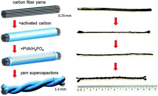 | ||
| Fig. 1 Schematic illustration of the fabrication process of all-carbon solid-state yarn supercapacitors (left) and corresponding photographs of carbon yarns of every fabrication step (right). | ||
Effect of activated carbon loading on hybrid carbon yarns
SEM was used to examine the morphology of hybrid carbon yarns. Fig. 2 shows that individual graphite filaments have a diameter of about 6–7 μm. Activated carbon particles have a wide range of sizes from less than 1 to 10 μm (also see Fig. S1b in the ESI†). Some activated carbon particles were directly deposited on graphite filaments, while more occupied voids among graphite filaments. With the increase of mass loading from 0.5 to 2 mg cm−1 in hybrid carbon yarns, more activated carbon particles stay in voids with some distance to graphite filaments. Activated carbon particles can provide considerable surface area for EDLC. However, their relatively low electrical conductivity would significantly limit electron transfer when they are away from current collectors.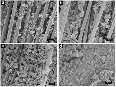 | ||
| Fig. 2 SEM images of hybrid carbon yarns with different loadings of activated carbon. (a) 0.5 mg cm−1, (b) 1.0 mg cm−1, (c) 1.5 mg cm−1, and (d) 2 mg cm−1. | ||
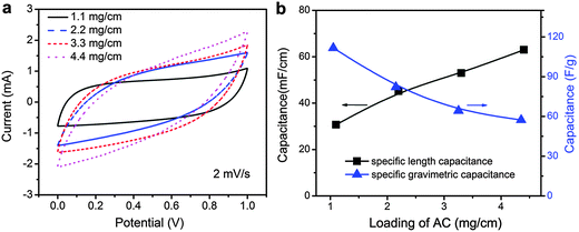
To optimize the mass loading of activated carbon in hybrid carbon yarns, electrochemical properties of 10 cm long yarn supercapacitors assembled using hybrid carbon yarns that contain different amounts of activated carbon were compared. The activated carbon mass loadings of 0.5, 1, 1.5, and 2 mg cm−1 in hybrid carbon yarns produce yarn supercapacitors containing 1.1, 2.2, 3.3, and 4.4 mg cm−1 of activated carbon (note that two 11 cm long hybrid carbon yarns were twisted into one 10 cm long yarn supercapacitor). Fig. 3a shows their CV curves at 2 mV s−1. The enclosed area of CV curves increases with higher activated carbon loading, indicating greater total capacitance. Fig. S2 in the ESI† suggests that the capacitance of carbon fiber yarns is very low (0.141 mF cm−1 at 2 mV s−1 measured in a 1 M H2SO4 electrolyte). Thus, most of the capacitance of the yarn supercapacitor can be attributed to activated carbon. Fig. 3b shows that the calculated specific length capacitance of the yarn supercapacitors from their CV curves increases from 30.7, 45.2, 53.0, to 63.0 mF cm−1 when the mass loading of activated carbon in yarn supercapacitors increases from 1.1 to 4.4 mg cm−1. In contrast, the specific gravimetric capacitance corresponding to the mass of activated carbon in yarn supercapacitors decreases from 111.7, 82.1, 64.2, to 57.3 F g−1. Fig. S3 in the ESI† shows that activated carbon used in this work has a specific gravimetric capacitance of 126.3 F g−1 at 2 mV s−1 measured in a 1 M H2SO4 electrolyte. The decrease in specific gravimetric capacitance suggests that EDLC contributed by activated carbon becomes less efficient when activated carbon particles are away from current collectors. Although higher AC loading can increase specific length capacitance, the efficiency of capacitive energy storage by activated carbon reduces significantly. Therefore, in the following studies, we focused on yarn supercapacitors with activated carbon loading at 2.2 mg cm−1, which provides both relatively high specific length capacitance at 45.2 mF cm−1 and specific gravimetric capacitance at 82.1 F g−1.
Electrochemical performance of yarn supercapacitors
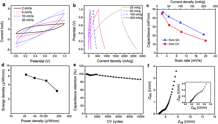
The electrochemical performance of the 10 cm yarn supercapacitor containing 2.2 mg cm−1 activated carbon was further characterized by CV and GC. CV curves of this device shown in Fig. 4a have a large enclosed area, indicating high capacitance. It becomes spindle-shaped at higher scan rates. Correspondingly, GC curves in Fig. 4b are symmetric triangular-shaped at lower discharge current densities. They become less symmetric with voltage drops at the beginning of the discharge process at higher discharge current densities. Fig. 4c shows that the specific length capacitance determined from CV curves of the device drops from 45.2, 28.0, 24.3 to 14.3 mF cm−1 when the CV scan rates increases from 2, 5, 10 to 20 mV s−1. Similarly, the specific length capacitance determined from GC curves decreases from 46.8, 39.7, 34.9 to 21.3 mF cm−1, when the discharge current density is increased from 25, 50, 100 to 200 mA g−1. The gravimetric capacitance of the device was also calculated, which is shown in Fig. S5 (ESI†). The specific length capacitance of the device is much higher than many recently reported fiber/yarn supercapacitors, which include multi-walled carbon nanotube/ordered mesoporous carbon composite fiber at 1.91 mF cm−1,28 polyelectrolyte-wrapped graphene/carbon nanotube core-sheath fiber at 5.3 mF cm−1,24 and multi-walled carbon nanotubes/carbon microfibers/carbon film at 6.3 mF cm−1.22 The specific length energy and power densities of the device are shown in Fig. 4d. At the current density of 25 mA g−1, it has an energy density of 6.5 μW h cm−1 and a power density of 27.5 μW cm−1. It can retain an energy density of 3.0 μW h cm−1 at a higher power density of 220 μW h cm−1. These power and energy densities are higher than those of many reported fiber/yarn supercapacitors containing various nanomaterials, such as reduced graphene oxide/MnO2 nanosheets/polypyrrole deposited stainless steel current collectors at 1.4 μW h cm−1 and 1.3 μW cm−1,45 activated carbon deposited natural fibers with stainless steel current collectors at 3.3 μW h cm−1,41 carbon fiber/polyaniline at 1.4 μW h cm−1 and 119 μW cm−1,46 carbon nanotube/MnO2/polymer fiber at 0.75 μW h cm−1 and 19.3 μW cm−1,54 multi-walled carbon nanotubes/carbon microfibers/carbon film at 0.7 μW h cm−1 and 13.7 μW cm−1,22 and polyelectrolyte-wrapped graphene/carbon nanotube core-sheath fiber at 0.0471 μW h cm−1 and 2.57 μW cm−1.24 Furthermore, the device reveals excellent cycling stability with 86.6% capacitance retentions after 10![[thin space (1/6-em)]](https://www.rsc.org/images/entities/char_2009.gif) 000 cycles at the scan rate of 20 mV s−1. We noticed that the rate capability of the yarn supercapacitor is relatively poor at fast scan rates or high discharge current densities (see Tables S1 and S2 in the ESI†), which can be attributed to that fact that activated carbon has lower electrical conductivity and the polymer gel electrolyte also has a slower ion transport. The rate capability can be improved by using more conductive nanomaterials, such as carbon nanotubes, graphene, and carbon onions.8,44 However, considering the various issues of nanomaterials as discussed in Introduction, yarn supercapacitors proposed in this work are based on commercially available and low cost carbon materials with unique merits. ESR of the yarn supercapacitor was also measured using EIS. Fig. 4f shows that its ESR is 4.9 Ω cm−1. The relatively small ESR implies that longer yarn supercapacitors can be fabricated, which are more beneficial for integrating yarn supercapacitors into wearable fabrics.
000 cycles at the scan rate of 20 mV s−1. We noticed that the rate capability of the yarn supercapacitor is relatively poor at fast scan rates or high discharge current densities (see Tables S1 and S2 in the ESI†), which can be attributed to that fact that activated carbon has lower electrical conductivity and the polymer gel electrolyte also has a slower ion transport. The rate capability can be improved by using more conductive nanomaterials, such as carbon nanotubes, graphene, and carbon onions.8,44 However, considering the various issues of nanomaterials as discussed in Introduction, yarn supercapacitors proposed in this work are based on commercially available and low cost carbon materials with unique merits. ESR of the yarn supercapacitor was also measured using EIS. Fig. 4f shows that its ESR is 4.9 Ω cm−1. The relatively small ESR implies that longer yarn supercapacitors can be fabricated, which are more beneficial for integrating yarn supercapacitors into wearable fabrics.
Performance of yarn supercapacitors of different lengths
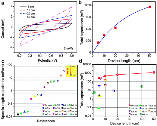
For applications in energy storage textiles, long yarns are required to build realistic weavable devices. Previous studies were often limited to devices with short lengths.54,55 The performance of fiber electrodes often deteriorates significantly with the increase of their length due to large resistances of electrodes.44 We assembled yarn supercapacitors of lengths 5, 10, 20, and 50 cm containing 2.2 mg cm−1 activated carbon. Fig. 5a shows their CV curves at 2 mV s−1. The total capacitance of yarn supercapacitors increases from 256, 451.7, 632.9 to 1164 mF when their length increases from 5 to 50 cm. Fig. 5b shows that the total capacitance increases linearly with the extension of length up to 10 cm, and the trend apparently deviates from linearity when the length is further extended. This is consistent with their CV curves in Fig. 5a, where the CV curves of the 5 cm and 10 cm yarn supercapacitors exhibit a more rectangular shape. Conversely, the CV curves of 20 cm and 50 cm yarn are spindle-shaped, suggesting higher resistances in the devices.We further compared the specific length capacitance of yarn supercapacitors at different lengths with various yarn/fiber supercapacitors reported in the literature. As shown in Fig. 5c, yarn supercapacitors reported here show the specific length capacitances of 51.2 mF cm−1 (5 cm), 45.2 mF cm−1 (10 cm), 31.65 mF cm−1 (20 cm), and 23.28 mF cm−1 (50 cm), which are much higher than many previous results. To the best of our knowledge, these values are among the highest specific length capacitances ever reported for yarn/fiber supercapacitors. The details of previous studies and their measurement conditions are listed in Table S3 in the ESI.† We also compared the total capacitance and the length of assembled yarn/fiber supercapacitors. As shown in Fig. 5d, yarn supercapacitors reported here demonstrate both high total capacitance and a large length.56–58
Mechanical flexibility and wearable knitted wristband
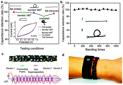
Fig. S4 in the ESI† shows that carbon fiber yarns used in this work have excellent mechanical strength with a Young's modulus of 255.7 GPa. They are mechanically strong enough to be knitted. The mechanical flexibility of yarn supercapacitors was tested by bending a 10 cm device at different angles or crumpling the device as shown in Fig. 6. Fig. 6a shows that CV curves of the device have minimal changes under different conditions. It can retain nearly 100% of its initial capacitance upon bending at different angles, and only exhibited a small decrease (<9%) when the whole device was crumpled. Fig. 6b shows that the device still retains 98% of its initial capacitance after 1000 bending cycles. Due to its excellent mechanical flexibility, we knitted one 30 cm and two 50 cm yarn supercapacitors together into a wearable wristband. The structure of this wristband is shown in Fig. 6c. The photo in Fig. 6d demonstrates its ability to light an LED indicator (for about 1 minute) and to be safely worn, just like other wearable devices. We believe that such a wearable wristband has vast applications in smart textile.Conclusions
We have successfully fabricated all-carbon solid-state yarn supercapacitors using commercially available activated carbon and carbon fiber yarns. Conductive carbon fibers concurrently serve as current collectors in yarn supercapacitors and as substrates for the deposition of activated carbon particles with large surface area. Two hybrid carbon yarn electrodes were twisted together in PVA/H3PO4 polymer gel. A 10 cm yarn supercapacitor with the optimum composition of 2.2 mg cm−1 activated carbon and 1 mg cm−1 carbon fibers shows a specific length capacitance of 45.2 mF cm−1 at 2 mV s−1, which is one of the highest specific length capacitances ever reported for yarn/fiber supercapacitors. It also exhibits an energy density of 6.5 μW h cm−1 and a power density of 27.5 μW cm−1, and can retain an energy density of 3.0 μW h cm−1 at a higher power density of 220 μW h cm−1. Due to the low equivalent series resistance at 4.9 Ω cm−1, long yarn supercapacitors up to 50 cm were demonstrated with high total capacitance up to 1164 mF. The all-carbon solid-state yarn supercapacitors also show excellent mechanical flexibility with small capacitance changes upon bending or being crumpled. Using three long yarn supercapacitors, a wearable wristband was knitted, and it can light an LED indicator, demonstrating strong potential for smart textile applications. Moreover, the fabrication method demonstrated in this work is based on commercially available safe carbon materials, which can be further scaled up for commercial exploration in the near future.Acknowledgements
This work was supported by the Ministry of Education, Singapore (MOE2011-T2-2-062 and 2013-T1-002-132) and the iFood program funded by Nanyang Technological University.References
- W. Jiang, D. Yu, Q. Zhang, K. Goh, L. Wei, Y. Yong, R. Jiang, J. Wei and Y. Chen, Adv. Funct. Mater., 2015, 25, 1063–1073 CrossRef CAS PubMed.
- P. K. Nayak and N. Munichandraiah, J. Solid State Electrochem., 2012, 16, 2739–2749 CrossRef CAS.
- K. Kostarelos, Nat. Biotechnol., 2008, 26, 774–776 CrossRef CAS PubMed.
- C. J. Smith, B. J. Shaw and R. D. Handy, Aquat. Toxicol., 2007, 82, 94–109 CrossRef CAS PubMed.
- M. A. C. Stuart, W. T. Huck, J. Genzer, M. Müller, C. Ober, M. Stamm, G. B. Sukhorukov, I. Szleifer, V. V. Tsukruk and M. Urban, Nat. Mater., 2010, 9, 101–113 CrossRef PubMed.
- S. Coyle, Y. Wu, K.-T. Lau, D. De Rossi, G. Wallace and D. Diamond, MRS Bull., 2007, 32, 434–442 CrossRef CAS.
- M. Pasta, F. La Mantia, L. Hu, H. D. Deshazer and Y. Cui, Nano Res., 2010, 3, 452–458 CrossRef CAS.
- K. Jost, C. R. Perez, J. K. McDonough, V. Presser, M. Heon, G. Dion and Y. Gogotsi, Energy Environ. Sci., 2011, 4, 5060–5067 CAS.
- L. Hu and Y. Cui, Energy Environ. Sci., 2012, 5, 6423–6435 Search PubMed.
- B. S. Shim, W. Chen, C. Doty, C. Xu and N. A. Kotov, Nano Lett., 2008, 8, 4151–4157 CrossRef CAS PubMed.
- L. Hu, M. Pasta, F. L. Mantia, L. Cui, S. Jeong, H. D. Deshazer, J. W. Choi, S. M. Han and Y. Cui, Nano Lett., 2010, 10, 708–714 CrossRef CAS PubMed.
- L. Bao and X. Li, Adv. Mater., 2012, 24, 3246–3252 CrossRef CAS PubMed.
- K. Cherenack and L. van Pieterson, J. Appl. Phys., 2012, 112, 091301 CrossRef PubMed.
- W. Zeng, L. Shu, Q. Li, S. Chen, F. Wang and X. M. Tao, Adv. Mater., 2014, 26, 5310–5336 CrossRef CAS PubMed.
- K. Jost, G. Dion and Y. Gogotsi, J. Mater. Chem. A, 2014, 2, 10776–10787 CAS.
- D. Yu, Q. Qian, L. Wei, W. Jiang, K. Goh, J. Wei, J. Zhang and Y. Chen, Chem. Soc. Rev., 2015, 44, 647–662 RSC.
- G. Sun, X. Wang and P. Chen, Mater. Today, 2015, 18, 215–226 CrossRef CAS PubMed.
- X. Wang, K. Jiang and G. Shen, Mater. Today, 2015, 18, 265–272 CrossRef CAS PubMed.
- H. Peng, Fiber-Shaped Energy Harvesting and Storage Devices, Springer, 2015 Search PubMed.
- Y. Meng, Y. Zhao, C. Hu, H. Cheng, Y. Hu, Z. Zhang, G. Shi and L. Qu, Adv. Mater., 2013, 25, 2326–2331 CrossRef CAS PubMed.
- P. Xu, T. Gu, Z. Cao, B. Wei, J. Yu, F. Li, J. H. Byun, W. Lu, Q. Li and T. W. Chou, Adv. Energy Mater., 2014, 4, 1300759 Search PubMed.
- V. T. Le, H. Kim, A. Ghosh, J. Kim, J. Chang, Q. A. Vu, D. T. Pham, J.-H. Lee, S.-W. Kim and Y. H. Lee, ACS Nano, 2013, 7, 5940–5947 CrossRef CAS PubMed.
- D. Harrison, F. Qiu, J. Fyson, Y. Xu, P. Evans and D. Southee, Phys. Chem. Chem. Phys., 2013, 15, 12215–12219 RSC.
- L. Kou, T. Huang, B. Zheng, Y. Han, X. Zhao, K. Gopalsamy, H. Sun and C. Gao, Nat. Commun., 2014, 5, 3754 CAS.
- Z. Yu and J. Thomas, Adv. Mater., 2014, 26, 4279–4285 CrossRef CAS PubMed.
- Y. Fu, X. Cai, H. Wu, Z. Lv, S. Hou, M. Peng, X. Yu and D. Zou, Adv. Mater., 2012, 24, 5713–5718 CrossRef CAS PubMed.
- X. Xiao, T. Li, P. Yang, Y. Gao, H. Jin, W. Ni, W. Zhan, X. Zhang, Y. Cao and J. Zhong, ACS Nano, 2012, 6, 9200–9206 CrossRef CAS PubMed.
- J. Ren, W. Bai, G. Guan, Y. Zhang and H. Peng, Adv. Mater., 2013, 25, 5965–5970 CrossRef CAS PubMed.
- B. Liu, D. Tan, X. Wang, D. Chen and G. Shen, Small, 2013, 9, 1998–2004 CrossRef CAS PubMed.
- Z. Yang, J. Deng, X. Chen, J. Ren and H. Peng, Angew. Chem., Int. Ed., 2013, 52, 13453–13457 CrossRef CAS PubMed.
- Q. Meng, H. Wu, Y. Meng, K. Xie, Z. Wei and Z. Guo, Adv. Mater., 2014, 26, 4100–4106 CrossRef CAS PubMed.
- Y. Li, K. Sheng, W. Yuan and G. Shi, Chem. Commun., 2013, 49, 291–293 RSC.
- K. Wang, Q. Meng, Y. Zhang, Z. Wei and M. Miao, Adv. Mater., 2013, 25, 1494–1498 CrossRef CAS PubMed.
- Q. Chen, Y. Meng, C. Hu, Y. Zhao, H. Shao, N. Chen and L. Qu, J. Power Sources, 2014, 247, 32–39 CrossRef CAS PubMed.
- X. Chen, L. Qiu, J. Ren, G. Guan, H. Lin, Z. Zhang, P. Chen, Y. Wang and H. Peng, Adv. Mater., 2013, 25, 6436–6441 CrossRef CAS PubMed.
- D. Yu, K. Goh, H. Wang, L. Wei, W. Jiang, Q. Zhang, L. Dai and Y. Chen, Nat. Nanotechnol., 2014, 9, 555–562 CrossRef CAS PubMed.
- J. Tao, N. Liu, W. Ma, L. Ding, L. Li, J. Su and Y. Gao, Sci. Rep., 2013, 3, 2286 Search PubMed.
- X. Ding, Y. Zhao, C. Hu, Y. Hu, Z. Dong, N. Chen, Z. Zhang and L. Qu, J. Mater. Chem. A, 2014, 2, 12355–12360 CAS.
- J. Ren, L. Li, C. Chen, X. Chen, Z. Cai, L. Qiu, Y. Wang, X. Zhu and H. Peng, Adv. Mater., 2013, 25, 1155–1159 CrossRef CAS PubMed.
- J. A. Lee, M. K. Shin, S. H. Kim, H. U. Cho, G. M. Spinks, G. G. Wallace, M. D. Lima, X. Lepró, M. E. Kozlov and R. H. Baughman, Nat. Commun., 2013, 4, 1970 Search PubMed.
- K. Jost, D. P. Durkin, L. M. Haverhals, E. K. Brown, M. Langenstein, H. C. De Long, P. C. Trulove, Y. Gogotsi and G. Dion, Adv. Energy Mater., 2015 DOI:10.1002/aenm.201401286.
- G. Sun, J. Liu, X. Zhang, X. Wang, H. Li, Y. Yu, W. Huang, H. Zhang and P. Chen, Angew. Chem., Int. Ed., 2014, 126, 12784–12788 CrossRef PubMed.
- G. Sun, X. Zhang, R. Lin, J. Yang, H. Zhang and P. Chen, Angew. Chem., Int. Ed., 2015, 127, 4734–4739 CrossRef PubMed.
- Y. Ma, P. Li, J. W. Sedloff, X. Zhang, H. Zhang and J. Liu, ACS Nano, 2015, 9, 1352–1359 CrossRef CAS PubMed.
- Y. Huang, H. Hu, Y. Huang, M. Zhu, W. Meng, C. Liu, Z. Pei, C. Hao, Z. Wang and C. Zhi, ACS Nano, 2015, 9, 4766–4775 CrossRef CAS PubMed.
- H. Jin, L. Zhou, C. L. Mak, H. Huang, W. M. Tang and H. L. W. Chan, Nano Energy, 2015, 11, 662–670 CrossRef CAS PubMed.
- B. Zheng, T. Huang, L. Kou, X. Zhao, K. Gopalsamy and C. Gao, J. Mater. Chem. A, 2014, 2, 9736–9743 CAS.
- T. Huang, B. Zheng, L. Kou, K. Gopalsamy, Z. Xu, C. Gao, Y. Meng and Z. Wei, RSC Adv., 2013, 3, 23957–23962 RSC.
- Y. Gogotsi, Mater. Res. Innovations, 2003, 7, 192–194 CrossRef CAS.
- N. Lewinski, V. Colvin and R. Drezek, Small, 2008, 4, 26–49 CrossRef CAS PubMed.
- K.-H. Liao, Y.-S. Lin, C. W. Macosko and C. L. Haynes, ACS Appl. Mater. Interfaces, 2011, 3, 2607–2615 CAS.
- S. Liu, T. H. Zeng, M. Hofmann, E. Burcombe, J. Wei, R. Jiang, J. Kong and Y. Chen, ACS Nano, 2011, 5, 6971–6980 CrossRef CAS PubMed.
- C. A. Poland, R. Duffin, I. Kinloch, A. Maynard, W. A. Wallace, A. Seaton, V. Stone, S. Brown, W. MacNee and K. Donaldson, Nat. Nanotechnol., 2008, 3, 423–428 CrossRef CAS PubMed.
- C. Choi, S. H. Kim, H. J. Sim, J. A. Lee, A. Y. Choi, Y. T. Kim, X. Lepró, G. M. Spinks, R. H. Baughman and S. J. Kim, Sci. Rep., 2015 DOI:10.1038/srep09387.
- Y. Liang, Z. Wang, J. Huang, H. Cheng, F. Zhao, Y. Hu, L. Jiang and L. Qu, J. Mater. Chem. A, 2015, 3, 2547–2551 CAS.
- D. Zhang, M. Miao, H. Niu and Z. Wei, ACS Nano, 2014, 8, 4571–4579 CrossRef CAS PubMed.
- T. Chen, L. Qiu, Z. Yang, Z. Cai, J. Ren, H. Li, H. Lin, X. Sun and H. Peng, Angew. Chem., Int. Ed., 2012, 51, 11977–11980 CrossRef CAS PubMed.
- J. Bae, Y. J. Park, M. Lee, S. N. Cha, Y. J. Choi, C. S. Lee, J. M. Kim and Z. L. Wang, Adv. Mater., 2011, 23, 3446–3449 CrossRef CAS PubMed.
Footnote |
| † Electronic supplementary information (ESI) available. See DOI: 10.1039/c5mh00108k |
| This journal is © The Royal Society of Chemistry 2015 |

