
Ultrabright fluorescent particles via physical encapsulation of fluorescent dyes in mesoporous silica: a mini-review
Igor
Sokolov
 abc
abc
aDepartment of Mechanical Engineering, Tufts University, Medford, Massachusetts, USA. E-mail: igor.sokolov@tufts.edu
bDepartment of Biomedical Engineering, Tufts University, Medford, Massachusetts, USA
cDepartment of Physics, Tufts University, Medford, Massachusetts, USA
First published on 17th May 2024
Abstract
Harnessing the power of mesoporous silica to encapsulate organic fluorescent dyes has led to the creation of an extraordinary class of nanocomposite photonic materials. These materials stand out for their ability to produce the brightest fluorescent particles known today, surpassing even the luminosity of quantum dots of similar spectrum and size. The synthesis of these materials offers precise control over the shape and size of the particles, ranging from the nano to the multi-micron scale. Just physical encapsulation of the dyes opens new possibilities for mixing different dyes within individual particles, paving the way for nearly limitless multiplexing capabilities. Moreover, this approach lays the groundwork for the development of highly sensitive sensors capable of detecting subtle changes in temperature and acidity at the nanoscale, among other parameters. This mini-review highlights the mechanism of synthesis, explains the nature of ultrabrightness, and describes the recent advancements and future prospects in the field of ultrabright fluorescent mesoporous silica particles, showcasing their potential for various applications.
1. Introduction
Templated sol–gel chemistry allows for the creation of highly ordered mesoporous materials with pore sizes between 2 and 30 nm. Mesoporous silica1–4 is of particular interest. Metastable silicic acid, condensing on inhomogeneities created by liquid crystal templates, essentially creates a silica replica of liquid crystals.2,5,6 As a result, the internal surface area of such materials exceeds thousands of square meters per gram. The group led by Geoffrey Ozin created a whole family of mesoporous silica films and particles of complex shapes that were typically seen only in the biological world.7–12Later, it was found that the particles could demonstrate extremely high fluorescence brightness after a simple encapsulation of fluorescent dyes inside the pores.13–15 The dye molecules were just physically added to the synthesizing bath without any modifications. The synthesized ultrabright mesoporous silica particles of micron sizes (micro-UMSP) demonstrated a brightness that was at least 10× higher,15,16 compared to polymeric particles of similar size that encapsulated the brightest quantum dots.17 The term ultrabrightness was introduced as brighter than quantum dots of similar size and spectra. Micron-sized fluorescent particles are of interest in many applications, for example, flow cytometry. Nevertheless, ultrabright mesoporous silica nanoparticles (nano-UMSP, also called Star-dots) are of much broader interest since they can probe deeper penetration with a much higher spatial resolution. Investigating the self-assembly mechanism allowed to design the synthesis of nano-UMSP of tens of nanometers in size.18
There have been many attempts to make fluorescent silica nanoparticles of high brightness.19–26 Most of these approaches utilized the covalent binding between fluorescent dye and silica. Recently, the use of tris(2,2A-bipyridyl)dichlororuthenium(II) hexahydrate (Rubpy) dye was reported to non-covalently doped silica nanoparticles.27 However, the brightness of these particles was not exceptionally high.
Physical encapsulation of fluorescent dyes inside nanoporous silica is a promising approach because of its simplicity. There is no need to modify fluorescent dye molecules as in alternative approaches, in which the dyes were covalently linked to the silica matrix.28 Moreover, as it turned out, the physical encapsulation gave substantially higher fluorescence brightness. The nature of such an unusual photonic phenomenon has been revealed in.16 Besides a general understanding of the reasons for attaining the ultrahigh fluorescence brightness, this knowledge has allowed to design ultrabright photonic sensors of temperature and pH29,30 as well as the particles for multiplexed detection.31,32
It is worth mentioning that although the covalent linkage of fluorescent dyes to silica particles not allowing to reach the brightness of the physically encapsulated dyes, the covalent linkage carries a number of advantages. The covalent link is stable with respect to aqueous and many nonaqueous environments. Oppositely, the particles with physically encapsulated dyes are sensitive to the presence of any organic solvents, which can wash out the encapsulated dyes. Even in an aqueous environment, the physically encapsulated dye tends to diffuse out. Here, we describe how this problem was addressed to make the particles suitable for quantitative fluorescence measurements within several weeks after the synthesis. Nevertheless, the problem of long-term storage of particularly nano-UMSP has not yet been completely solved.
Here, we overview the mechanism of the assembly of mesoporous silica particles, which is key to the rational design of UMSP. We describe the solution to the major bottlenecks in the development of these particles, such as the problem of dye leakage. We also present the recent developments, which demonstrate the assembly of various sensors (exampled by the ratiometric sensors of temperature and acidity) and the almost unlimited capability of ultrabright fluorescent nanoparticles to be used in multiplexing labeling. Future developments will be discussed in the conclusions. Because this minireview is focused on UMSP, we do not describe other fluorescent nanoparticles available to the researchers these days.28,33 We give just a brief comparative overview in the Conclusions.
2. Mechanisms and control of geometrical shape and fluorescence ultrabrightness
2.1. The mechanism of self-assembly of mesoporous silica particles
The synthesis is based on the idea of preferential condensation of metastable silicic acid on liquid-crystal-templates.3,11 Due to the appropriate complementarity of charge, geometry, and stereochemistry in an organic–inorganic co-assembly, the inorganic portion mineralizes to yield the rigidified nanophase. Manipulation of the surfactant packing parameters headgroup charge, co-surfactants, solvents, co-solvents, and organic additives have been used to template particular structures.34 Various amphiphiles can be organized into supramolecular templating assemblies. The liquid crystal template is created by amphiphilic molecules, in this particular case, cationic surfactants. By having an appropriate concentration, the liquid crystals can have phases of different symmetry. A particular surfactant concentration used in the majority of described works was just above the critical micellar concentration corresponding to the nematic phase of liquid crystals.Fig. 1 shows a schematic of the mechanism of self-assembly of UMSP. Panel (a) shows the molecular building blocks of UMSP. Self-assembly of cationic surfactant molecules forms nematic liquid crystals. It is formed by templating surfactant molecules at the beginning of the assembly due to the appropriately chosen concentration of the surfactant as mentioned above. Nematic liquid crystals serve as condensation centers for deprotonated silicate, which is supplied by liquid silica precursors, Fig. 1b. In the next stage, small pieces of nematic liquid crystals fuse together to form “seed” particles, Fig. 1c. One can see in this panel the mesostructure of the silica particles with fluorescent dye molecules, which are physically encapsulated inside of the typically cylindrical pores of particles.
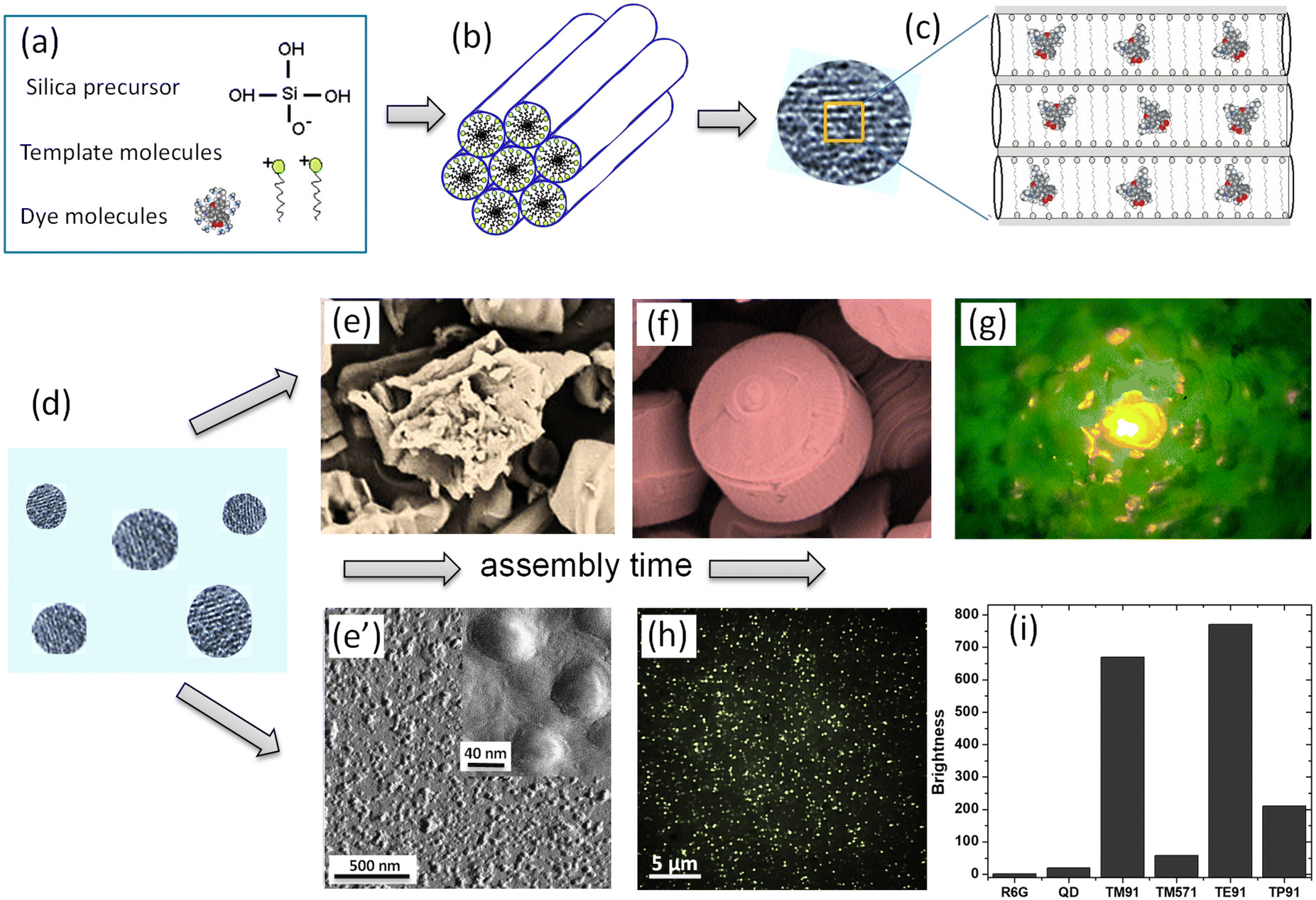 | ||
| Fig. 1 A schematic of the mechanism of self-assembly of ultrabright mesoporous silica particles (UMSP). (a) The building blocks of the particles: template cationic surfactant molecules, which will form liquid crystals; a mineralizable inorganic anion, deprotonated silicate; and dye molecules. (b) Deprotonated silicate condenses on the surface of the nematic liquid crystals created by the template molecules. (c) Small nematic crystals are fused into silica mesoporous structures, “seed” particles, which carry fluorescent dye molecules encapsulated inside the cylindrical channels of the particles. (d) Initially sticky and not fully polymerized seed particles of 10–20 nm in size will now be the building blocks for both nano and micron size UMSP. (e) The seeds assemble in larger micron-size aggregates if allowed to stay in the synthesizing bath. (f) The micron-size aggregates have further been developed into mesoporous silica shapes with well-aligned cylindrical mesochannels. (g) An example of an ultrabright fluorescent discoid illuminating the landscape of surrounding polymer. (e′) When suppressing the aggregation of seed particles, the seeds shown in panel (d) will be assembled and polymerized as separate nanoparticles. (h) A fluorescent image of the obtained nano-UMSP. (i) Relative fluorescent brightness of different nano-UMSP (TM91 is 40 nm, TM571 is 23 nm, TE91 is 52 nm, and TP91 is 45 nm (ref. 13)) versus single R6G molecule, ∼30 nm water-dispersible (coated for protection and water “solubility”60) CDSe/ZnS quantum dot with green fluorescence. [Compiled using images taken from ref. 18, 30, 37 and 61. Reproduced from ref. 18 with permission from John Wiley and Sons, copyright 2008; Reproduced from ref. 30 with permission from RCS, copyright 2021; Reproduced from ref. 37 with permission from RCS, copyright 2017; Reproduced from ref. 61 with permission from John Wiley and Sons, copyright 2010.]. | ||
Starting from this stage, the synthesis of nano and micron size UMSP diverges. Initially sticky and not fully polymerized seeds of 10–20 nm in size (Fig. 1d) can assemble in larger micron size aggregates35,36 if allowed to stay in the synthesizing bath, Fig. 1e. As was shown,37–39 these seeds have initially random orientation of the pores. But later, the cylindrical channels start to align, which is driven by the minimization of energy of the random pore orientations. At the end of this process, well-defined shapes with well-aligned pores are formed, Fig. 1g. The assembled shapes can reach up to a few hundred microns, form nanoporous thin films,40–46 spheres,47–49 curved shaped solids,42,50,51 tubes,52,53 rods, discoids, and fibers,42,50,54,55 membranes,56 and monoliths.57 The mechanism of formation of these shapes is dictated by the local minima of free energy of the forming shapes; see the cited references for details. Fig. 1g shows an example of an ultrabright fluorescent discoid of a polymer cavity. The particle is so bright that it illuminates the landscape of the surrounding polymer.
To assemble nano-UMSP, the aggregation of the seed particles (Fig. 1d) has to be suppressed. The seed particles can slightly grow and polymerize while staying as separate nano-sized particles. Fig. 1e′ depicts an atomic force microscopy image of the particles extracted from the synthesizing bath at this stage. Fig. 1h shows a fluorescent image of these particles recorded with the help of an optical fluorescent microscope. This approach was described to create the first ultrabright fluorescent nanoparticles in.13,18,58,59 A simple dilution with water was chosen to stop the synthesis process. The nanoparticles with encapsulated rhodamine 6G fluorescent dye demonstrated brightness substantially higher than the brightest CdS quantum dots of similar size (when coated to make them compatible with aqueous media) and spectra, Fig. 1i.
2.2. The mechanism of creation of ultrahigh fluorescence brightness
Initially, it was found that the encapsulated fluorescent dye was packed inside mesoporous silica at a very high concentration. Such concentrations of free dyes dissolved in water led to quenching of fluorescence, which was revealed in a highly specific change of the absorbance and fluorescence spectra. Fig. 2a shows an example of the dependence of the fluorescence brightness of UMSP (both nano and micron sizes) as a function of the concentration of rhodamine 6G dye inside the particles. The same was measured for the free dye dissolved in water. One can see that the fluorescence brightness of free dye reaches a maximum, and then starts dropping for higher concentration of the dyes. Such behavior is well-known and addressed to self-quenching of fluorescence due to the formation of non-radiative energy release paths of formed dimers and even trimers of the dye molecules. At the same time, the brightness of silica particles keeps growing with the increase of encapsulated dye concentration. (Note that the brightness shown in Fig. 2 is normalized for a unit volume of the particles.) Remarkably, the concentrations of the fluorescent dye inside of UMSP can reach ∼100 times higher concentrations without fluorescence quenching compared to that in water. Furthermore, it was found that the fluorescence spectrum of UMSP was identical to that of a highly diluted free dye in water. Thus, the encapsulated dye behaves like the free individual dye molecules that do not see their neighbors.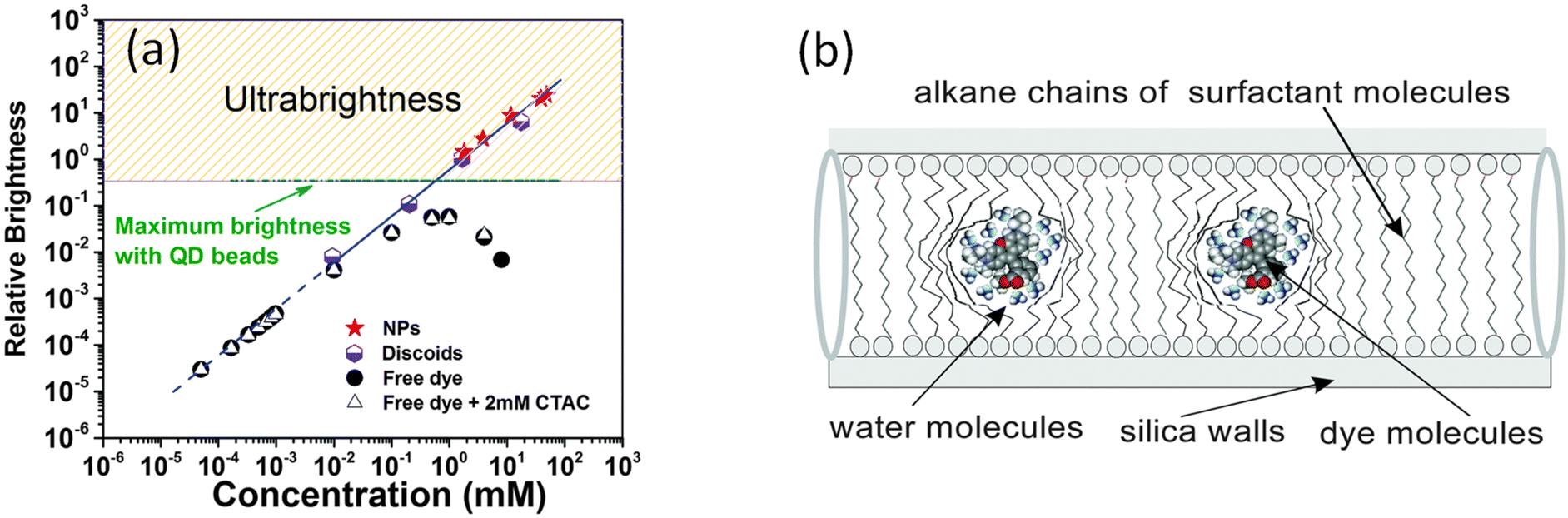 | ||
| Fig. 2 The mechanism of ultrabrightness. (a) Comparative brightness as a function of fluorescent dye (rhodamine 6G dye) concentration per 10 × 10 × 10 nm3 volume of both micro- and nano-UMSP, water solution of the dye, and surfactant-dye solution (shown for reference to exclude the influence of surfactant on fluorescence of free dye). The dashed line shows an ideally additive fluorescence, which would come from R6G dye molecules that do not change the quantum yield compared to free dye in low concentrations in water. (b) A detailed schematic of the caging of the dye molecules in the fluidic environment of nanochannels created by the alkane chains of the templating surfactant molecules. [Reproduced from ref. 16 with permission from RCS, copyright 2016.]. | ||
The investigation of this mechanism16 revealed that the encapsulated fluorescent dye molecules entrapped inside nanochannels of UMSP indeed behave as an almost free dye. Fig. 2b explains it. The nanochannels are filled with alkane chains of surfactant templating molecules, which surround the dye molecules. Both dyes and the head groups of the surfactant molecules are cationic, which results in the repulsion between dye molecules and silica walls coated with the head groups of the surfactant molecules. Thus, the dye molecules tend to locate in the center of the channel. The same charge of the dye molecules helps to prevent molecular dimers. However, similar charges of the dye molecules are present in water as well. The reason for the substantial decrease in the number of dimers inside silica channels was found to be a substantial decrease in the translational (along the channels) diffusion coefficient of the dye molecules. It was directly measured in,62 and found to be almost a hundred million times smaller than in water. At the same time, the measurements of the rotational diffusion coefficient of the dye molecules showed that the value of this coefficient was only a few times smaller than that of free dye in water.16 In other words, the dye molecules are free to move in their cages, to rotate but are prohibited to move toward each other. At the same time, it is the dynamic collisions between dye molecules that is one of the major causes of fluorescence quenching. These collisions lead to the formation of short-leaving dimers, which do not allow for the attainment of high fluorescence of the dye solution when the dye concentration becomes high. The mechanism was further corroborated in16 by the measurements of fluorescence lifetime, quantum yield, and concentrations of J and H dimers formed inside UMSP.
2.3. Substantial increase in photostability of the encapsulation dyes
It is well known that nanoencapsulation of various organic molecules increases molecule stability.63,64 This effect has been observed for fluorescent dyes encapsulated in mesoporous silica.18,65 When using near-infrared fluorescent dyes, the effect of increased stability is quite impressive. Instead of hours, the fluorescence keeps its fluorescent properties against photobleaching for weeks.66Fig. 3 shows the photobleaching of cells labeled with free LS277 NIR dye and the same dye encapsulated inside nano-UMSP. One can see that the fluorescence of nanoparticles is still very bright even after nine weeks, whereas the free dye is completely bleached by that time. It should be noted that strictly speaking, this is a mix of photobleaching (due to environmental light) and time stability of the dye.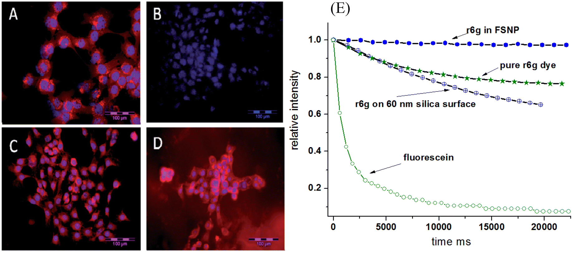 | ||
| Fig. 3 Improved photobleaching of fluorescent dyes encapsulated in nano-UMSP. (A–D) NIR fluorescence microscopy of 4T1luc tumor cells. (A) Cells 24 h post-treatment with LS277 dye; (B) re-imaging of cells shown in (A) after 9 weeks; (C) cells 24 h post-treatment with NP2_LS277 particles; (D) re-imaging of cells shown in (C) after 9 weeks; red: NIR fluorescence; blue: DAPI nuclear stain; scale bar 100 μm. (E) Photobleaching of rhodamine 6G dye, both free and encapsulated inside of mesoporous silica; the breaching of the same dye physically adsorbed on solid silica nanoparticles is also shown. Photobleaching of fluorescein green dye of the same optical density is shown as a photobleaching standard. All photostability experiments were measured in aqueous environments. [Compiled using images taken from ref. 18 and 66. Reproduced from ref. 18 with permission from John Wiley and Sons, copyright 2008; Reproduced from ref. 66 with permission from RCS, copyright 2014.]. | ||
An example of photobleaching of rhodamine 6G dye, both free and encapsulated inside of nano-UMSP, is shown in Fig. 3E. For comparison, the breaching of the same dye physically adsorbed on solid silica nanoparticles is also shown. Photobleaching of fluorescein green dye is shown as a photobleaching standard. Fast photobleaching of fluorescein green, seen in Fig. 3E, demonstrates a high stability of rhodamine 6G dye in general. Importantly, one can see an improvement in the photobleaching of the dye encapsulated in nano-UMSP compared to the free dye. It is interesting that the dye physically adsorbed on solid silica nanoparticles demonstrates less photostability compared to free dye.
2.4. The major problem of the first ultrabright particles, dye leakage, and its solution
The major bottleneck of the physical encapsulation of fluorescent dyes inside pores of silica particles, in particular, nanoparticles, was the leakage of the encapsulated dyes. While it could be useful for some applications like slow drug release, it is a substantial bottleneck for any quantitative applications, like flow cytometry, sensing, and quantitative labeling.The solution to this problem was different for micro and nano-UMSP. In the case of micro-UMSP, it was possible to find the synthesis that produced self-sealed pores,15Fig. 4a–d. As a result, the encapsulated dye was physically trapped and could only leak through a small number of defects. The use of the same dye allowed to detect the presence of those defects (Fig. 4c), and minimize it. Fig. 4d shows the dye leakage from self-sealed particles dispersed in water versus the mesoporous silica particles with completely open pores (fiber-looking particles). One can see a substantial decrease in the leakage. It can be minimized even further after several washings.
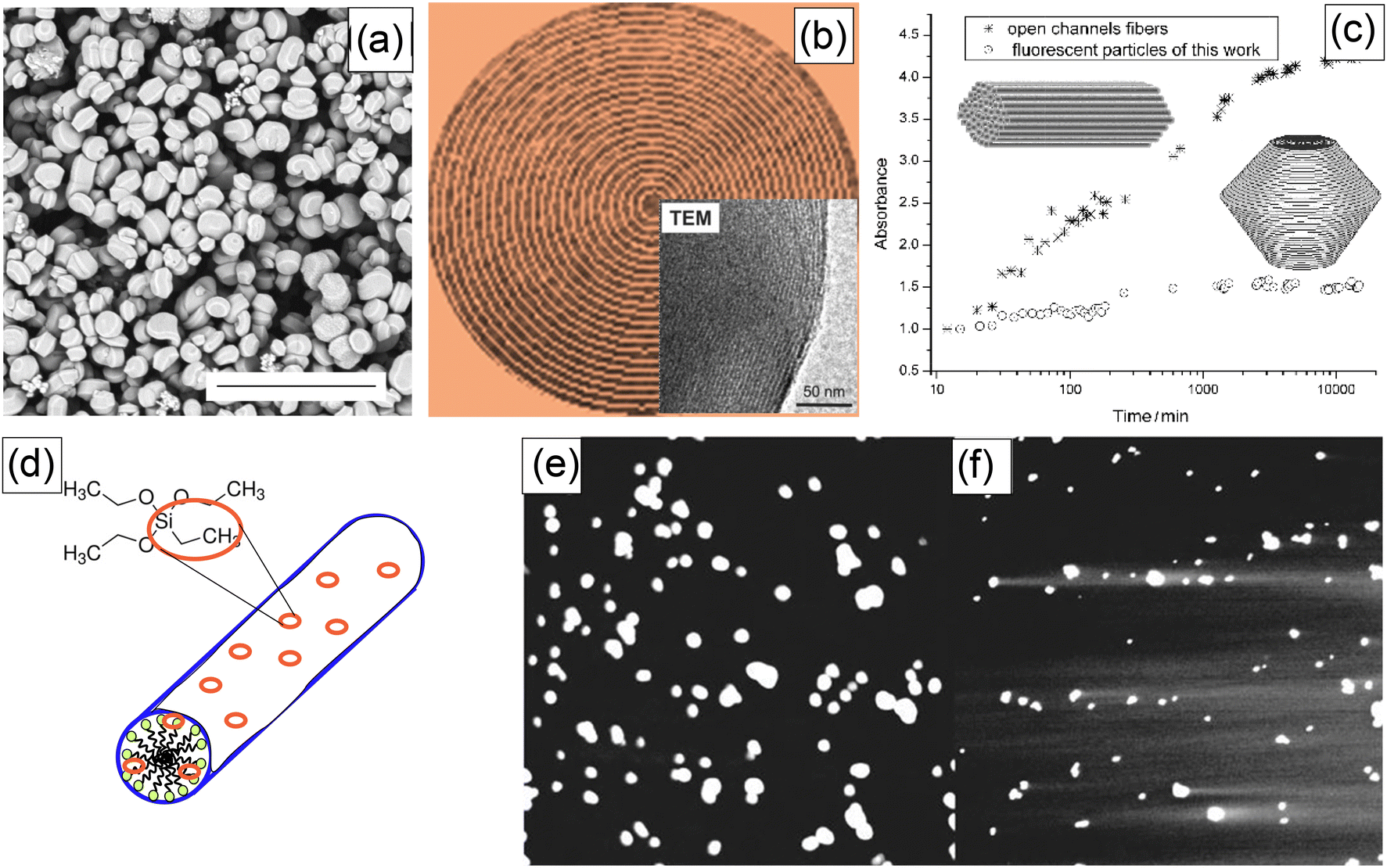 | ||
| Fig. 4 Solutions of the dye leakage problem using self-sealed pore geometry (works for micro-UMSP) (a–c), and adding a small number of hydrophobic groups to silica matrix (for both micro and nano-UMSP) (d–f). (a) SEM image of self-sealed particles (the scale bar is 20 μm). (b) A schematic showing the geometry of self-sealed pores/channels (the insert is a TEM image of the edge of a micro-UMSP). (c) The leakage of the encapsulated dye from the self-sealed particles versus open-pore particles (fibers). (d) A schematic showing decoration of silica mesophase with hydrophobic group; ethyltriethoxysilane (ETES) examples a co-precursor of silica with hydrophobic ethyl groups. The leakage test for fluorescent micro-UMSP: (e) a representative confocal fluorescent image of the synthesized particles with hydrophobic groups, and (f) the same synthesis but no hydrophobic groups; the fluorescent tails of the dye leaked out of the particles are clearly seen in this case. [Compiled using images taken from ref. 15 and 67. Reproduced from ref. 15 with permission from John Wiley and Sons, copyright 2007; Reproduced from ref. 67 with permission from RCS, copyright 2011.]. | ||
The mesoporous silica nanoparticles are too small to “bend” the channels to self-seal the cylindrical pores (it would require a large amount of energy). A solution was suggested in13,14,67 by adding a small number of hydrophobic groups into the silica matrix, Fig. 4e. This solution works for both micro and nano-UMSP. Because of the very small size of the pores, even the small number of hydrophobic groups can prevent water from moving inside the particles, therefore preventing the dye from being defused into the surrounding aqueous environment. It is similar to the known Lotus effect,68 when geometry substantially enhances the hydrophobicity of surfaces. In the case of nanoparticles, it was possible to find an optimal amount of hydrophobic groups to keep water from penetrating inside the particles while keeping the overall surface of the particles sufficiently hydrophilic.13,14 Although the problem of leakage has not been entirely solved, this method allows the encapsulated dyes to be kept inside particles for a sufficiently long time (months). It is typically sufficient for most of quantitative applications.
2.5. The challenge of functionalization of UMSP
The attachment of ligand molecules to UMSP is highly desirable because it can substantially expand the areas of application of such particles. Although micro-UMSP were used for discrimination of cancer and normal cells,69 it was based on just physical interactions between cells and micro-UMSP. In general, the functionalization of micro-UMSP is not expected to be challenging. A standard silica chemistry will presumably work. Nevertheless, it has not been demonstrated as of today.Researchers have focused on the functionalization of nano-UMSP because of broader application interest. Although there are some protocols for functionalization based on just aqueous chemistry, most of the protocols require organic solvents. It is a challenge because organic solvents can effectively penetrate inside the open pores of nano-UMSP and wash out the physically encapsulated dyes. This challenge was addressed by finding a sufficiently mild organic solvent (EDTA), which turned out to be safe enough for the encapsulated fluorescent molecules.58,70 This method allowed to keep the brightness of the particles in the ultrabright regime.
Later, another successful coating of nano-UMSP was developed using functional constructs, specially synthesized molecules, that were attached to the particle surface through just physical hydrophobic interaction.71Fig. 5a shows three different ways of functionalizing nano-UMSP with folic acid: covalent attachment, physical coating, and a mix of these two. A functional molecular construct of poloxamer (PF127) and folic acid (FA) was used for the physical coating.
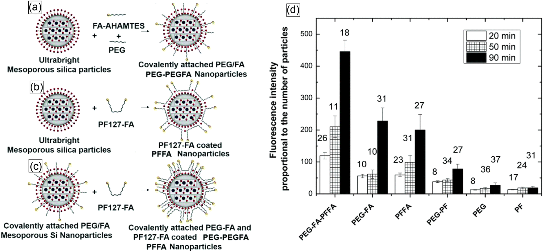 | ||
| Fig. 5 Schematic of the methods used to synthesize functionalized nano-UMSP. (a) Synthesis of ultrabright mesoporous silica nanoparticles with covalent attachment of folic acid and PEG. (b) Coating ultrabright mesoporous silica particles with PF127-FA. (c) Coating covalently attached PEG-FA mesoporous silica nanoparticles with PF127-FA. (d) Functional targeting of human cervical epithelial cancer (HeLa) cells using functionalized nano-UMSP. Fluorescence intensity (in arbitrary units), which is proportional to the number of nano-UMSP particles accumulated in cells after 20, 50, and 90 minutes of incubation. The number above each column bar represents the number of analyzed cells. The error bar shows one standard deviation. The results for folate functionalized nano-UMSP (SiSB-PEGFA-PFFA, SiSB-PFFA, SiSB-PEGFA) and no-folate control nanoparticles (SiSB-PEG-PF, SiSB-PEG, SiSB-PF) are shown. The experiments were repeated 3 times, with three independent wells of a multiwell plate seeded and treated in parallel, and a picture of each was acquired. [Reproduced from ref. 71 with permission from RCS, copyright 2019.]. | ||
Fig. 5b shows the results of functional targeting of human cervical epithelial cancer (HeLa) cells using all three types of particles. It was shown that the particles can effectively detect cancer cells.70 Later, it was found that just a physical coating of nano-UMSP is even more efficient for the discrimination of cancer cells than the functionalization based on covalent bonds.71
3. Applications
3.1. Targeting of cells and tumors
One of the most popular applications of fluorescent nanoparticles is the labeling/targeting of particular molecules in biological cells and tissues. Fig. 6a shows an example of successful targeting of folate receptors on the surface of human cervical epithelial cells using folic acid functionalized nano-UMSP.70 These particles were used to distinguish cancerous and precancerous cervical epithelial cells from normal cells. Due to the high brightness of the particles, the difference is clearly seen after a short incubation of 15 minutes.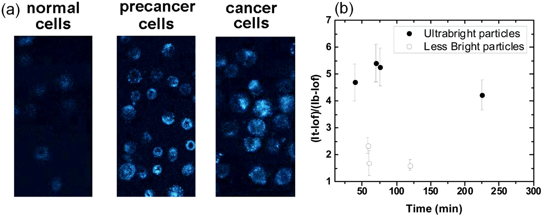 | ||
| Fig. 6 Targeting of folate receptors on the surface of human cervical epithelial cells using folic acid functionalized nano-UMSP. (a) Fluorescent images of normal, precancerous, and cancerous human cervical epithelial cells incubated with fluorescent nanoporous folate-functionalized silica nanoparticles for 15 minutes. (b) Relative contrasts of tumors (fluorescence of tumor relative to the background) tagged with folic acid functionalized nano-UMSP and ∼100× less bright particles (similar to “regular” fluorescent nanoparticles of the brightness comparable to a quantum dot of similar spectrum). The average relative contrast versus time since particle injection is shown. The error bar corresponds to one standard deviation. [Compiled using images taken from ref. 70 and 71. Reproduced from ref. 70 with permission from Elsevier, copyright 2013; Reproduced from ref. 71 with permission from RCS, copyright 2019.]. | ||
Fig. 6b shows the overall advantage of using ultrabright nanoparticles compared to regular ones. Folate functionalized nano-UMSP were injected in zebrafish xenografts with human cervical cancer cells and mini tumors.32 The relative to the background contrast of tumor tumors in zebrafish is shown when using nano-UMSP and ∼100× less bright regular nanoparticles. One can see that ∼2–3 times higher contrast is attained ∼3 times faster when using nano-UMSP compared to less bright particles. It is interesting to note that a longer waiting time does not help to reach a higher contrast when using less bright particles.
3.2. Almost unlimited multiplexing
The photostability of encapsulated dyes makes the synthesized UMSP suitable for multiple quantitative measurements, such as flow cytometry, multiplexing. Multiplexing means using particles with complex fluorescent spectra, which are distinguishable when using such methods as fluorescent microscopy or flow cytometry. Besides photostability, the physical encapsulation of fluorescent dyes inside mesoporous silica results in the preservation of fluorescence spectra of the encapsulated dyes. It was demonstrated that the resulting spectrum of nanoparticles with encapsulated multiple dyes could be accurately predicted even when the dyes are very close to each other so that the Förster Resonance Energy Transfer (FRET) occurs.72Encapsulation of up to five different dyes in single UMSPs was first demonstrated for microparticles.32Fig. 7a shows an example of fluorescence images of micro-UMSP containing varying amounts of dyes mixed within each particle. In many applications, it is advantageous to use excitation light of just one wavelength. These can be done by using spectroscopically aligned dyes to transfer the energy through FRET from the first excited dye to the next one, Fig. 7b. Later, a similar multiplexing was demonstrated for nano-UMSP.31 Again, up to five different fluorescent dyes aligned in the FRET regime were used. It is important to note that the use of different dyes did not lead to differences in the nanoparticle sizes. To the best of our knowledge, nobody was able to demonstrate such a large number of distinguishable spectra, in particular when using nanoparticles, nano-UMSP. The latter is particularly interesting for applications of flow cytometry to study exosomes or when the number of sought receptors on the cell surface is small.73–75
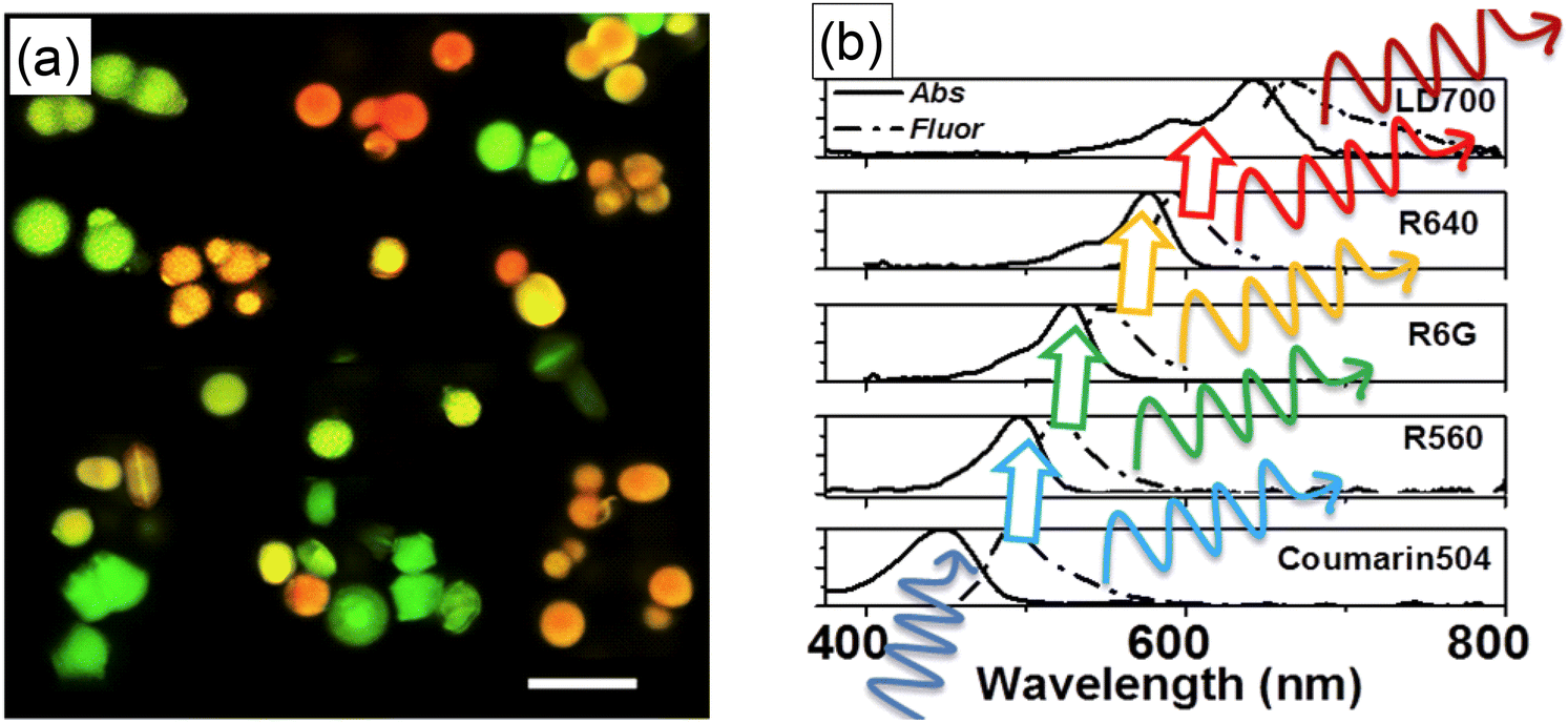 | ||
| Fig. 7 Ultrabright fluorescent particles having complex spectra excited with a single wavelength. (a) Fluorescent confocal image of multiplexing micro-UMSPs excited at 488 nm containing varying amounts of coumarin 504, rhodamine 560, rhodamine 6G, and rhodamine 640. The scale bar is 10 μm. The particles with different fluorescent spectra are physically mixed in this image. (b) Sequential FRET can be used to transfer the excitation energy from one dye to the next. The absorbance and fluorescence spectra of five dyes in sequence are shown. Because the efficiency of FRET can be controlled by changing the distance between the dye molecules, the resulting spectrum can have a mix of fluorescence of all encapsulated dyes. [Reproduced from ref. 32 with permission from RCS, copyright 2017.]. | ||
Considering the large number of fluorescent dyes commercially available and the possible number of combinations of those dyes inside each particle, one can conclude that the number of different fluorescence spectra is practically unlimited. The limitations should come from the detection sensitivity rather than from the number of available different spectra. Furthermore, it is instructional to note that distinguishable spectra can also be created not necessarily by using different dyes but rather by different proportions of the same dyes within each particle. For example, it was demonstrated that it is possible to distinguish five different fluorescent spectra of UMSPs using just two different dyes in different proportions.31 The average error of identification of each spectrum was of the order of 2–7% (this number was found by simulating flow cytometry of cells labeled with ∼90 nano-UMSP).
3.3. A platform for building sensors
Fluorescence of the majority of the nanoparticles depends on the environment. However, only a few types of fluorescent nanoparticles can work as sensors, i.e., a “device” that can produce a sensing signal independent of the particular measurement, for example, the intensity of the excitation light. To avoid such dependence, one of the most popular methods is to use the ratiometric approach.76 Using either various doping or two fluorescent dyes (one sensitive and one reference dye) within one particle, one can measure the ratio of fluorescence intensities that is independent of the intensity of the excitation light.It should be noted that “regular” dye-doped nanoparticles typically require two excitation wavelengths to produce a sufficiently strong fluorescence signal coming from both dyes. This is rather hard to make technically for optically inhomogeneous systems. The close proximity of the dyes encapsulated inside UMSP makes it possible to use FRET to excite both fluorescent dyes with a single wavelength light. The first UMSP sensor was built to measure temperature.30 Highly repeatable measurements of temperature were demonstrated with the uncertainty down to 0.4 K and constant sensitivity of ∼1%/K in the range of 20–50 °C, which is of particular interest for biomedical applications. The use of single nano-UMSP (“nanothermometers”) to measure temperature was also demonstrated.30 As an example, 5–8 nanothermometers were sufficient to measure the temperature with an error of 2 K (with a measurement time of ∼ 0.7 s). Later, using the same approach, it was demonstrated that even individual nano-UMSP could be used to measure the temperature because the spectral difference between individual nano-UMSP was rather small.72 This is important because there is no direct control of the ratio of two encapsulated dyes in each nanoparticle.
It was also possible to measure distributions of temperature in 3D in hydrogel, shown in Fig. 8. The measured distribution of temperature was in good agreement with numerical simulations. To explain the difficulty of such measurements without UMSP nanothermometers, it is instructional to think about the use of classical ratiometric fluorescence measurements of temperature by using a mix of two fluorescent dyes.77 The dyes can be homogeneously mixed in simple media like water. However, hydrogel is a molecularly inhomogeneous medium. The two used different dyes interact with such media differently. As a result, the temperature measurements can be seriously compromised. Obviously, the dye ratio is preserved inside UMSP. The second less obvious advantage of using UMSP is the self-filtering of the medium. Since the dye is not sufficiently bright to work with extremely low concentrations, it requires quite a noticeable amount of dye in the medium. Because such media starts working as a filter due to light absorbance by the dye, it is very hard to restore the actual fluorescence ratio in the inhomogeneous media. Due to the high fluorescent brightness of UMSP, it was possible to use extremely low concentrations of the particles to avoid the problems of self-filtering.
 | ||
| Fig. 8 Ultrabright fluorescent nanothermometers- nanoparticles allow measuring 3D mapping of temperature distribution. (a) 3D temperature distribution of a heated wire in hydrogel simulated with a stationary numerical model solution. (b) 3D temperature measurements using nano-UMSP. [Reproduced from ref. 30 with permission from RCS, copyright 2021.]. | ||
Nano-UMSP was also developed for simultaneous measurements of acidity (pH) and temperature.78 They worked with three dyes encapsulated in nano-UMSP. FRET pairs of temperature-responsive, pH-sensitive, and reference dyes are physically encapsulated inside a porous silica matrix of ∼50 nm particles. The particles can be used to measure both the temperature in the biologically relevant range (20 to 50 °C) and pH within 4 to 7 range with the error of 0.54 °C and 0.09, respectively. The sensitivity of the developed UMSP sensor ranged between 0.2–3% °C−1 and 2–6% pH−1. It should be noted that the above-described sensors were developed for measurements and biological environments. The independence of the fluorescence spectrum was tested against the presence of different ions presented in the simulated body fluids.
4. Conclusion and outlook
Here, we described the mechanisms of synthesis of ultrabright fluorescent silica particles, UMSP, and explained the nature of ultrahigh fluorescence brightness. This knowledge has allowed for designing other variations of UMSP, to address the major problems of physical encapsulation of dyes, its leakage, and to develop different protocols of functionalization of UMSP. Several promising applications of UMSP were also described. The use of UMSP as ratiometric sensors looks very promising because of the high signal-to-noise ratio. Measurements of temperature at the nanoscale with high speed and temperature resolution will move frontiers of our fundamental knowledge of thermodynamics at the nanoscale. The same can be said about the measurements of acidity. This technology can be applied to measure the presence of specific ions, etc.As to the application of UMSP for multiplexing, it looks very significant as well. It virtually suggests the ability to do many hundreds or thousands (and maybe more) of measurements in parallel. Nevertheless, it should be noted that it will require the use of linear demultiplexing algorithms. Such algorithms exist and can be easily implemented in the existing hardware. However, it will require essentially recording the entire spectrum. Currently, most flow cytometry equipment still operates by recording fluorescence through just several spectroscopic bands. The spectroscopic resolution is then limited by the fluorescence “leakage” between different spectroscopic bands. Thus, implementing UMSP for multiplexing will require more marketing to convince the manufacturers to implement demultiplexing algorithms.
As was discussed, the overviewed approach allows for the synthesizing of both micron- and nano-size UMSP. It is instructional to compare these two types of UMSP. Since the brightness of UMSP is proportional to their volumes, the larger particles are always fluorescently brighter. It is despite the fact that nanoscale UMSP demonstrate the ability to encapsulate higher concentrations of the dyes without fluorescence quenching (Fig. 2). This difference is not sufficient to compensate for the particle volume, and therefore, micron size UMSP are always brighter. The solution to the dye leakage problem has been addressed so far differently in both nano and micro UMSP. In principle, the dye leakage can further be addressed, for example, by applying different coatings. At present, the described solutions seem to be sufficient, at least for research purposes, when the particles are not intended to be stored for longer than a month. From the application point of view, nano-UMSP have already demonstrated their advantages in biomedical research. No specific applications of micron-size UMSP have been reported. Being a novel enabling material, it will definitely take time before such applications can be found.
Although this mini-review is focused on UMSP, it is instructional to compare UMSP with other bright fluorescent particles available to researchers. The advantage of ultrabrightness is the faster and easier detection of such particles. As was described (Fig. 6b), it allows capturing the presence of tumors faster and with higher contrast. Therefore, we compare UMSP with the brightest existing particles, in particular, quantum dots (QD). Compared to individual QD or QD encapsulated inside of polymeric micron particles, the UMSP demonstrate higher brightness. The reason for this seems to be purely quantitative. The organic dyes can withstand much closer proximity without quenching fluorescence compared to QD. In addition, the size of the organic fluorescent dye molecules is smaller compared to quantum dots. As a result, one can pack more dye molecules inside of the same volume.
It is important to recognize that the photostability of organic dyes is less than that of quantum dots (or any inorganic fluorophore). Nevertheless, it is typically sufficient for practical applications, in particular, because of the increased stability of the dye after encapsulation in mesoporous silica. Further, organic dyes do not suffer from oxidation in many environments, including physiological buffers. As a result, UMSP containing organic fluorescent dyes do not require special protection, which is needed for QD. Furthermore, UMSP do not demonstrate any fluorescence blinking, which is a problem for QD when used for tracing experiments. (It should be noted, though, that there are recent developments of QD without blinking.) Finally, there are concerns about the toxicity of the brightest quantum dots.79 However, there are promising developments of QD without the use of toxic heavy elements.80 At the end of the comparison, it should be noted that recently developed polymeric QD (PD) seem to be comparable by brightness with UMSP. However, there has been no direct comparison so far. A large variety of fluorescent dyes available for the assembly of UMSP still gives an advantage to UMSP compared to PD. But because of the small but still existing dye leakage problem, PD looks preferable if a long storage is needed.
Conflicts of interest
I. S. is a co-inventor of ultrabright fluorescent mesoporous silica particles and nanothermometers (the intellectual rights are assigned to Clarkson University).Acknowledgements
Support from NSF grants CBET 1911253 and 2110757 is acknowledged. Any opinions, findings, and conclusions or recommendations expressed in this material are those of the authors and do not necessarily reflect the views of the National Science Foundation.References
- S. Schacht, Q. Huo, I. G. Voigt-Martin, G. D. Stucky and F. Schuth, Science, 1996, 273, 768–771 CrossRef CAS PubMed.
- H. P. Lin and C. Y. Mou, Science, 1996, 273, 765–768 CrossRef CAS PubMed.
- C. T. Kresge, M. Leonowicz, W. J. Roth, J. C. Vartuli and J. C. Beck, Nature, 1992, 359, 710–712 CrossRef CAS.
- D. Zhao, J. Feng, Q. Huo, N. Melosh, G. H. Fredrickson, B. F. Chmelka and G. D. Stucky, Science, 1998, 279, 548–552 CrossRef CAS PubMed.
- J. C. Vartuli, K. D. Schmitt, C. T. Kresge, W. J. Roth, M. E. Leonowicz, S. B. Mccullen, S. D. Hellring, J. S. Beck, J. L. Schlenker, D. H. Olson and E. W. Sheppard, Chem. Mater., 1994, 6, 2317–2326 CrossRef CAS.
- S. Inagaki, Y. Fukushima and K. Kuroda, Zeolites and Related Microporous Materials: State of the Art 1994, 1994, vol. 84, pp. 125–132 Search PubMed.
- S. M. Yang, I. Sokolov, N. Coombs, C. T. Kresge and G. A. Ozin, Adv. Mater., 1999, 11, 1427–1431 CrossRef CAS.
- I. Sokolov, H. Yang, G. A. Ozin and C. T. Kresge, Adv. Mater., 1999, 11, 636–642 CrossRef CAS.
- H. Yang, G. A. Ozin and C. T. Kresge, Adv. Mater., 1998, 10, 883–887 CrossRef CAS.
- H. Yang, N. Coombs, I. Sokolov and G. A. Ozin, J. Mater. Chem., 1997, 7, 1285–1290 RSC.
- H. Yang, N. Coombs and G. A. Ozin, Nature, 1997, 386, 692–695 CrossRef CAS.
- H. Yang, N. Coombs, I. Sokolov and G. A. Ozin, Nature, 1996, 381, 589–592 CrossRef CAS.
- E. B. Cho, D. O. Volkov and I. Sokolov, Adv. Funct. Mater., 2011, 21, 3129–3135 CrossRef CAS.
- E. B. Cho, D. O. Volkov and I. Sokolov, Small, 2010, 6, 2314–2319 CrossRef CAS PubMed.
- I. Sokolov, Y. Kievsky and J. M. Kaszpurenko, Small, 2007, 3, 419–423 CrossRef CAS PubMed.
- V. Kalaparthi, S. Palantavida and I. Sokolov, J. Mater. Chem. C, 2016, 4, 2197–2210 RSC.
- M. Han, X. Gao, J. Z. Su and S. Nie, Nat. Biotechnol., 2001, 19, 631–635 CrossRef CAS PubMed.
- I. Sokolov and S. Naik, Small, 2008, 4, 934–939 CrossRef CAS PubMed.
- S. Shibata, T. Taniguchi, T. Yano and M. Yamane, J. Sol-Gel Sci. Technol., 1997, 10, 263–268 CrossRef CAS.
- H. Ow, D. R. Larson, M. Srivastava, B. A. Baird, W. W. Webb and U. Wiesner, Nano Lett., 2005, 5, 113–117 CrossRef CAS PubMed.
- D. R. Larson, A. Heikal, H. Ow, M. Srivastava, U. Wiesner, B. Baird and W. W. Webb, Biophys. J., 2003, 84, 586a Search PubMed.
- R. P. Bagwe, C. Y. Yang, L. R. Hilliard and W. H. Tan, Langmuir, 2004, 20, 8336–8342 CrossRef CAS PubMed.
- L. Wang and W. H. Tan, Nano Lett., 2006, 6, 84–88 CrossRef CAS PubMed.
- X. J. Zhao, R. P. Bagwe and W. H. Tan, Adv. Mater., 2004, 16, 173–176 CrossRef CAS.
- H. H. Yang, H. Y. Qu, P. Lin, S. H. Li, M. T. Ding and J. G. Xu, Analyst, 2003, 128, 462–466 RSC.
- S. Kim, H. E. Pudavar and P. N. Prasad, Chem. Commun., 2006, 2071–2073, 10.1039/b600926c.
- S. Santra, P. Zhang, K. Wang, R. Tapec and W. Tan, Anal. Chem., 2001, 73, 4988 CrossRef CAS PubMed.
- A. Burns, H. Ow and U. Wiesner, Chem. Soc. Rev., 2006, 35, 1028–1042 RSC.
- S. A. M. A. Peerzade, N. Makarova and I. Sokolov, Nanomaterials, 2021, 11, 1524 CrossRef CAS PubMed.
- V. Kalaparthi, B. Peng, S. A. M. A. Peerzade, S. Palantavida, B. Maloy, M. E. Dokukin and I. Sokolov, Nanoscale Adv., 2021, 3, 5090–5101 RSC.
- S. A. M. A. Peerzade, N. Makarova and I. Sokolov, Nanomaterials, 2020, 10, 905 CrossRef CAS PubMed.
- S. Palantavida, B. Peng and I. Sokolov, Nanoscale, 2017, 9, 4881–4890 RSC.
- V. Gubala, G. Giovannini, F. Kunc, M. P. Monopoli and C. J. Moore, Cancer Nanotechnol., 2020, 11, 1 CrossRef CAS.
- S. M. Yang, H. Yang, N. Coombs, I. Sokolov, C. T. Kresge and G. A. Ozin, Adv. Mater., 1999, 11, 52–55 CrossRef CAS.
- S. P. Naik and I. Sokolov, Solid State Commun., 2007, 144, 437–440 CrossRef CAS.
- S. P. Naik, S. P. Elangovan, T. Okubo and I. Sokolov, J. Phys. Chem. C, 2007, 111, 11168–11173 CrossRef CAS.
- I. Sokolov, V. Kalaparthi, D. O. Volkov, S. Palantavida, N. E. Mordvinova, O. I. Lebedev and J. Owens, Phys. Chem. Chem. Phys., 2017, 19, 1115–1121 RSC.
- V. Kalaparthi, S. Palantavida, N. E. Mordvinova, O. I. Lebedev and I. Sokolov, J. Colloid Interface Sci., 2016, 491, 133–140 CrossRef PubMed.
- D. O. Volkov, J. Benson, Y. Y. Kievsky and I. Sokolov, Phys. Chem. Chem. Phys., 2010, 12, 341–344 RSC.
- S. Piana, M. Reyhani and J. D. Gale, Nature, 2005, 438, 70–73 CrossRef CAS PubMed.
- I. Yu. Sokolov, G. A. Ozin, G. S. Henderson, H. Yang and N. Coombs, Adv. Mater., 1997, 9, 917–921 CrossRef CAS.
- G. A. Ozin, C. T. Kresge and H. Yang, Adv. Mater., 1998, 10, 883–887 CrossRef.
- H. Yang, I. Yu. Sokolov, N. Coombs, O. Dag and G. A. Ozin, J. Mater. Chem., 1997, 7, 1755–1761 RSC.
- H. Yang, N. Coombs, I. Yu. Sokolov and G. A. Ozin, J. Mater. Chem., 1997, 7, 1285–1290 RSC.
- H. Yang, N. Coombs, I. Yu. Sokolov and G. A. Ozin, Nature, 1996, 381, 589–592 CrossRef CAS.
- D. Zhao, P. Yang, N. Melosh, J. Feng, B. F. Chmelka and G. D. Sucky, Adv. Mater., 1998, 10, 1380–1385 CrossRef CAS.
- G. A. Ozin, H. Yang, N. Coombs and I. Yu. Sokolov, J. Mater. Chem., 1998, 8, 743–750 RSC.
- S. Schacht, Q. Huo, I. G. Voigt-Martin, G. D. Stucky and F. Schuth, Science, 1996, 273, 768–771 CrossRef CAS PubMed.
- M. Grun, I. Lauer and K. K. Unger, Adv. Mater., 1997, 9, 254–257 CrossRef.
- G. A. Ozin, H. Yang, I. Yu. Sokolov and N. Coombs, Adv. Mater., 1997, 9, 662–667 CrossRef CAS.
- D. O. Volkov, J. Benson, Y. Y. Kievsky and I. Sokolov, Phys. Chem. Chem. Phys., 2009, 12, 341–344 RSC.
- M. Yang, I. Yu. Sokolov, N. Coombs, C. T. Kresge and G. A. Ozin, Adv. Mater., 1999, 11, 1427–1431 CrossRef.
- F. Kleitz, F. Marlow, G. D. Stucky and F. Schuth, Chem. Mater., 2001, 13, 3587–3595 CrossRef CAS.
- P. Schmidt-Winkel, P. Yang, D. I. Margolese, B. F. Chmelka and G. D. Stucky, Adv. Mater., 1999, 11, 303–307 CrossRef CAS.
- Y. Kievsky and I. Sokolov, IEEE Trans. Nanotechnol., 2005, 4, 490–494 CrossRef.
- D. Zhao, P. Yang, B. F. Chmelka and G. D. Stucky, Chem. Mater., 1999, 11, 1174–1178 CrossRef CAS.
- N. A. Melosh, P. Davidson and B. F. Chmelka, J. Am. Chem. Soc., 2000, 122, 823–829 CrossRef CAS.
- S. Palantavida, N. V. Guz and I. Sokolov, Part. Part. Syst. Charact., 2013, 30, 804–811 CrossRef CAS.
- E. B. Cho, D. O. Volkov and I. Sokolov, Small, 2010, 6, 2314–2319 CrossRef CAS PubMed.
- I. L. Medintz, H. T. Uyeda, E. R. Goldman and H. Mattoussi, Nat. Mater., 2005, 4, 435–446 CrossRef CAS PubMed.
- I. Sokolov and D. O. Volkov, J. Mater. Chem., 2010, 20, 4247–4250 RSC.
- Y. Y. Kievsky, B. Carey, S. Naik, N. Mangan, D. Ben-Avraham and I. Sokolov, J. Chem. Phys., 2008, 128, 151102 CrossRef CAS PubMed.
- C. Ispas, I. Sokolov and S. Andreescu, Anal. Bioanal. Chem., 2009, 393, 543–554 CrossRef CAS PubMed.
- M. T. Bazana, C. F. Codevilla and C. R. de Menezes, Curr. Opin. Food Sci., 2019, 26, 47–56 CrossRef.
- S. P. Naik and I. Sokolov, in Nanoparticles: Synthesis, Stabilization, Passivation and Functionalization, ed. R. Nagarajan, ACS, 2008, ch. 16, pp. 214–224 Search PubMed.
- S. Palantavida, R. Tang, G. Sudlow, W. Akers, S. Achilefu and I. Sokolov, J. Mater. Chem. B, 2014, 2, 3107–3114 RSC.
- D. O. Volkov, E. B. Cho and I. Sokolov, Nanoscale, 2011, 3, 2036–2043 RSC.
- A. Lafuma and D. Quéré, Nat. Mater., 2003, 2, 457–460 CrossRef CAS PubMed.
- S. Iyer, C. D. Woodworth, R. M. Gaikwad, Y. Y. Kievsky and I. Sokolov, Small, 2009, 5, 2277–2284 CrossRef CAS PubMed.
- S. Palantavida, N. V. Guz, C. D. Woodworth and I. Sokolov, Nanomed. Nanotechnol., 2013, 9, 1255–1262 CrossRef CAS PubMed.
- S. A. M. A. Peerzade, X. D. Qin, F. J. F. Laroche, S. Palantavida, M. Dokukin, B. Peng, H. Feng and I. Sokolov, Nanoscale, 2019, 11, 22316–22327 RSC.
- M. Iraniparast, B. R. Peng and I. Sokolov, Sensors, 2023, 23, 3471 CrossRef CAS PubMed.
- X. Z. Liu, Z. Y. Zong, M. D. Xing, X. H. Liu, J. Li and D. B. Liu, Nano Lett., 2021, 21, 8817–8823 CrossRef CAS PubMed.
- C. Flynn, B. Höchst and P. Knolle, Eur. J. Immunol., 2019, 49, 187–188 Search PubMed.
- R. A. Dragovic, G. P. Collett, P. Hole, D. J. P. Ferguson, C. W. Redman, I. L. Sargent and D. S. Tannetta, Methods, 2015, 87, 64–74 CrossRef CAS PubMed.
- E. J. McLaurin, L. R. Bradshaw and D. R. Gamelin, Chem. Mater., 2013, 25, 1283–1292 CrossRef CAS.
- D. Ross, M. Gaitan and L. E. Locascio, Anal. Chem., 2001, 73, 4117–4123 CrossRef CAS PubMed.
- S. Peerzade, N. Makarova and I. Sokolov, Nanomaterials, 2021, 11, 1524–1531 CrossRef CAS PubMed.
- R. Hardman, Environ. Health Perspect., 2006, 114, 165–172 CrossRef PubMed.
- B. Gidwani, V. Sahu, S. S. Shukla, R. Pandey, V. Joshi, V. K. Jain and A. Vyas, J. Drug Delivery Sci. Technol., 2021, 61, 102308 CrossRef CAS.
| This journal is © The Royal Society of Chemistry 2024 |