 Open Access Article
Creative Commons Attribution 3.0 Unported Licence
Controlling the steepness of gate-opening behavior on elastic layer-structured metal–organic framework-11 via solvent-mediated phase transformation†
Shotaro
Hiraide
 *,
Keisuke
Nishimoto
and
Satoshi
Watanabe
 *
*
Department of Chemical Engineering, Kyoto University, Nishikyo, Kyoto 615-8510, Japan. E-mail: hiraide@cheme.kyoto-u.ac.jp; nabe@cheme.kyoto-u.ac.jp
First published on 17th June 2024
Abstract
Metal–organic frameworks (MOFs), particularly flexible MOFs, have garnered significant attention because of their potential in various applications due to their unique ability to undergo reversible structural transitions in response to guest adsorption, the so-called gate-opening behavior, making their scale-up synthesis increasingly important. This study focuses on the high-concentration synthesis of elastic layer-structured MOF-11 (ELM-11), one of the earliest observed flexible MOFs capable of gate adsorption. We demonstrate that, while low-concentration synthesis yields pre-ELM-11, the precursor to ELM-11, high-concentration conditions favor the formation of a metastable phase of pre-ELM-11. Although both can be transformed into ELM-11 by heating under vacuum and, consequently, exhibit nearly identical adsorption properties, the steepness of the S-shaped curve upon gate opening varies significantly. Our investigation reveals two main points: one is that the metastable phase of pre-ELM-11 can be transformed into its stable phase through extended aging in a solvent-mediated phase transformation process. The other is that the phase of pre-ELM-11 affects the crystallite size and, consequently, the cooperative deformation domain size within the framework structure, directly impacting the steepness of the gate-opening behavior according to the structural transition-type adsorption equation. We also demonstrate that seeding the stable phase during synthesis can expedite the solvent-mediated phase transformation, offering a practical approach for the efficient production of high-quality ELM-11. These findings provide valuable insights into the complex interplay between synthesis conditions, structural properties, and adsorption behavior in flexible MOFs, paving the way for their future industrial applications.
1 Introduction
Metal–organic frameworks (MOFs) are crystalline porous materials consisting of metal ions or clusters linked by organic ligands. They offer a unique combination of properties, including high surface area, adjustable pore size, and versatile functionalization options.1,2 One of the most striking properties of certain MOFs is their ability to undergo reversible structural transitions in response to external stimuli, such as guest adsorption, temperature, pressure, or light. They are referred to as “flexible MOFs”,3 “soft porous crystals”,4 or “switchable MOFs”5 and are promising candidates for a wide range of applications, including gas storage and separation, sensing, and drug delivery.6–9 Additionally, recent advances have identified their potential as actuators in the realm of soft robotics.10 As interest in industrial applications surges, the scalability of flexible MOF synthesis becomes crucial.Considering the limitations of reactor size and solvent volume, scaling up typically involves high-concentration synthesis. However, MOF synthesis is notably sensitive to experimental conditions. A significant change caused by altering synthesis conditions is the formation of structural isomers of the target MOF.11 For example, in the case of the IRMOF series with relatively longer ligands, high-concentration conditions lead to doubly interpenetrated jungle-gym frameworks, while dilute solutions result in non-interpenetrated structures.12 Synthesis temperature also influences MOF phases, as demonstrated by MIL-88B(V) and MIL-101(V) transforming into MIL-47 at 473 K.13 Changing solvents can yield entirely different structures of ELM-12: methanol, ethanol, 1-propanol, and 1-butanol produce 2D stacked layers with flexibility, whereas 1-hexanol and 1-octanol result in a rigid framework with 3D geometry.14 Reaction time also affects MOF geometry, as Huang et al. showed that during crystal growth of a Zn-based MOF, a layered crystal forms first, followed by a transition to a pillared-layer structure induced by screw dislocation and an associated growth spiral with the dissolution of the initial layered crystal.15 These instances highlight that scale-up synthesis of a targeted flexible MOF may encounter unforeseen challenges.
Even when a desired framework structure of a target flexible MOF is achieved under varying synthesis conditions, the characteristics of the flexible MOF might change. According to classical nucleation theory, higher concentration and lower temperature conditions tend to produce smaller particles. The feature of guest-induced structural transition in flexible MOFs, often referred to as “gate opening” or “breathing”, is known to be dependent on their particle sizes, which becomes particularly significant in particles of sub-micrometer size.16 Small particles typically exhibit one of the following two trends: one involves a higher shift of the gate-opening pressure (the threshold pressure at which the flexible MOF transforms from the closed state to the open phase, encapsulating guest molecules), and the other is that the flexible MOF no longer takes the closed phase, even under vacuum, thereby displaying a type I adsorption isotherm for the open structure. Although these trends seem contradictory from a thermodynamics perspective regarding adsorption-induced structural transition17—that is, reducing particle size destabilizes the open phase compared to the closed phase in the former case, while in the latter case it stabilizes—both are thought to be due to the reduced cooperative ability resulting from a higher proportion of surfaces.16 As the former case opens the possibility of tuning the gate-opening pressure by controlling particle size, this size effect has been explored with great interest, both experimentally18–28 and computationally.29–33 However, less attention has been paid to the decrease in the steepness of the S-shaped curve upon gate opening, typically coupled with its higher shift due to downsizing. One hypothesis for this phenomenon is that it reflects a significantly broader activation energy distribution in small grains.16,34–36 Elucidating key factors that determine the magnitude of the slope of the adsorption isotherm is crucial, as most potential applications of flexible MOFs rely on their distinctive responsiveness.
In the present study, we focused on the high-concentration synthesis of elastic layer-structured MOF-11 (ELM-11, [Cu(BF4)2(bpy)2]; bpy = 4,4′-bipyridine), one of the first flexible MOFs observed to undergo adsorption-induced structural transition.37 Specifically, the synthesis yields its hydrated form, known as pre-ELM-11 ([Cu(bpy)(H2O)2(BF4)2]·bpy),38 which transforms into ELM-11 upon heating under vacuum. Over the past twenty years since the discovery of ELM-11, its distinct gate-opening behavior has spurred a variety of experimental and theoretical studies.39–51 A recent investigation highlighted its superior performance in CO2 adsorption separation processes,52 fueling discussions on its industrialization.53–59
Despite being one of the “most investigated MOFs”, the high-concentration synthesis of ELM-11 exhibits unusual behavior. In this paper, we first demonstrate that high-concentration synthesis results in the structural isomer of pre-ELM-11, which is a metastable structure different from that initially reported by Blake et al.38 Our previous study revealed that this structural isomer is prone to form when ELM-11 is exposed to air.60 Intriguingly, both “stable” pre-ELM-11 from low-concentration synthesis and “metastable” pre-ELM-11 from high-concentration synthesis can transform into ELM-11 by heating under vacuum, and therefore, the resulting ELM-11 exhibits the same CO2 adsorption capacity and gate-opening pressure; however, the steepness of the S-shaped curve varies. Further investigation in high-concentration synthesis reveals that extended stirring of the mixed solution at room temperature (referred to as the aging process) converts the metastable pre-ELM-11 into stable pre-ELM-11. A counterintuitive trend in particle size emerges, where the average particle size decreases as aging time increases, suggesting that this phase change is driven by solvent-mediated phase transformation.61,62 We also demonstrate that the key difference between stable- and metastable-derived ELM-11 lies in the peak widths of the X-ray diffraction pattern (XRD), specifically, the crystallite size, which likely influences the steepness of the S-shaped curve according to theoretical isotherm equations for structural transition-type adsorption (STA equation).63 Lastly, we discuss a method to expedite the synthesis of stable pre-ELM-11, or ELM-11 with pronounced gate opening, drawing on the mechanism of the solvent-mediated phase transformation.
2 Experimental
2.1 Chemicals
Copper(II) tetrafluoroborate (Cu(BF4)2, 45% aqueous solution), 4,4′-bipyridyl (bpy, 98.0%), and methanol (99.8%) were purchased from Kanto Chemical Co., Inc. (Japan), Tokyo Chemical Industry Co., Ltd. (Japan), and Kishida Chemical Co., Ltd. (Japan), respectively. All chemicals were used as received. Aqueous solutions were prepared by dissolving the original chemicals in ultrapure water (>18 MΩ cm, Arium Mini Plus, Sartorius, Germany).2.2 Synthesis of pre-ELM-11 particles
A bpy methanol solution was added dropwise over 2 h using a syringe pump into a Cu(BF4)2 aqueous solution in a vial while being stirred at 1200 rpm with a magnetic stirrer. We conducted syntheses at both low and high concentrations, using two concentration sets for bpy methanol solution and the Cu(BF4)2 aqueous solution ([bpy], [Cu(BF4)2]): (0.2 mol L−1 and 0.1 mol L−1) for the lower concentration and (1.6 mol L−1 and 0.8 mol L−1) for the higher concentration. Typically, the volumes of bpy and Cu(BF4)2 solutions mixed were 9.88 and 10.87 mL, respectively, corresponding to a volume ratio of 1![[thin space (1/6-em)]](https://www.rsc.org/images/entities/char_2009.gif) :
:![[thin space (1/6-em)]](https://www.rsc.org/images/entities/char_2009.gif) 1.1. After the completion of the dropwise addition, the mixture was continuously stirred with a magnetic stirrer at 1200 rpm for 24 h (i.e., the aging time). The synthesized blue particles were then collected by vacuum filtration, washed with ultrapure water, and dried under vacuum overnight. For the high-concentration synthesis, we also examined the influence of the aging time by sampling the particles at various aging times from the same batch. All the procedures were conducted at room temperature (approximately 297 K).
1.1. After the completion of the dropwise addition, the mixture was continuously stirred with a magnetic stirrer at 1200 rpm for 24 h (i.e., the aging time). The synthesized blue particles were then collected by vacuum filtration, washed with ultrapure water, and dried under vacuum overnight. For the high-concentration synthesis, we also examined the influence of the aging time by sampling the particles at various aging times from the same batch. All the procedures were conducted at room temperature (approximately 297 K).
We also conducted a seed-added synthesis. Initially, pre-ELM-11 particles were synthesized under conditions of high concentration, with an aging time of 94 h. We then pulverized the obtained particles using an agate mortar to produce seeds. In the subsequent synthesis, we prepared the same reactant concentrations as above ([bpy], [Cu(BF4)2] = (1.6 mol L−1 and 0.8 mol L−1)), and added the seeds to the Cu(BF4)2 solution before slowly adding the bpy solution. The amount of seeds added corresponded to 10 wt% of the theoretical precipitation expected without seeds.
2.3 Characterization
Scanning electron microscopy (SEM) images were obtained using a JSM-6700F field emission SEM (JEOL Ltd., Japan). Pre-ELM-11 particles were coated with Au (thickness: 7.0 nm) prior to imaging using a Q150TS turbo-pumped sputter coater (Quorum Technologies Ltd., UK) to minimize charging problems. The particle size distribution of the resultant pre-ELM-11 particles was calculated by measuring the size of at least 100 particles from the SEM images.Powder XRD patterns were measured in our laboratory and at the BL02B2 and BL13XU beamlines of the SPring-8 synchrotron facility, Japan. In our laboratory, we utilized an UltimaIV/285/DX (Rigaku Corp., Japan) with Cu Kα radiation (40 kV and 40 mA) to characterize pre-ELM-11 samples. At BL02B2, the time course of XRD patterns during the transition from pre-ELM-11 to ELM-11 was observed by heating at 373 K under vacuum with a large Debye–Scherrer-type six MYTHEN detector setup,64,65 where the wavelength of the incident X-rays was 0.0799932 nm. Additionally, the impact of aging time on the XRD pattern of pre-ELM-11 was measured. At BL13XU, ELM-11, obtained by heating at 393 K under vacuum for 10 h, was measured with a large Debye–Scherrer-type six LAMBDA 750k detector setup66 and incident X-rays of 0.0495401 nm.
The adsorption isotherms of CO2 on ELM-11 at 273 K were recorded using a BELSORP-mini X (MicrotracBEL Corp., Japan). Before each isotherm measurement, the pre-ELM-11 particles were activated at 393 K for 10 h under a vacuum (<10 Pa) to convert them to ELM-11.
2.4 Analysis
The obtained adsorption isotherms on ELM-11 were fitted using the STA equation:63 | (1) |
 | (2) |
The crystallite size of ELM-11 was evaluated from the synchrotron XRD patterns obtained at BL13XU, applying the following Scherrer equation:
 | (3) |
3 Results and discussion
3.1 Synthesis of pre-ELM-11 under low and high concentration conditions
Fig. 1a displays a SEM image of particles produced through high-concentration synthesis. These particles are characterized by their flat shapes with long sides measuring approximately 10 μm, a feature consistent with those synthesized through low concentration methods (refer to Fig. S1, ESI†) and aligning with previous reports.59,60Fig. 1b presents the XRD patterns of particles synthesized at both low and high concentrations. While the XRD pattern from the low-concentration synthesis resembles the theoretical pattern of pre-ELM-11 originally reported by Blake et al.,38 the pattern from the high-concentration synthesis shows a mixture of pre-ELM-11 and another substance. Our previous study revealed that this substance is a framework isomer of pre-ELM-11, less stable than the original structure by 5.5 kJ per mol-Cu and tends to form when ELM-11 is exposed to air.60 The distinction between the “stable” and “metastable” pre-ELM-11 lies in the arrangement of square grids composed of Cu ions, bpy, and H2O: the stable pre-ELM-11 exhibits a zigzag arrangement, while the metastable pre-ELM-11 presents a straight arrangement, as depicted in Fig. 1c and d, respectively. The time course of XRD patterns for the particles synthesized at high concentration (Fig. 1e) shows that, upon heating at 373 K under vacuum, the peaks indicative of both stable and metastable pre-ELM-11 vanished, and the peaks corresponding to the closed phase of ELM-11 (ref. 44) (Fig. 1f) emerged, confirming the transformational capability of pre-ELM-11 into ELM-11, regardless of the square grids' arrangement (see also Fig. S2, ESI† for the thermogravimetric analysis). Reflecting this phenomenon, Fig. 1g demonstrates that the CO2 adsorption isotherm of ELM-11 at 273 K was nearly identical for both reactant concentrations, concerning the gate-opening/-closing pressure and saturated adsorption amount. However, there was a significant difference in the steepness of the S-shaped curve upon gate opening/closing; for instance, the pressure at which the adsorption amount reached 3 mmol g−1 was 39 kPa and 45 kPa under low and high concentration conditions, respectively. These findings indicate that both stable and metastable pre-ELM-11 ultimately yield the same ELM-11 but differ in aspects that affect the steepness of the gate-opening behavior.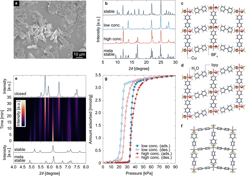 | ||
| Fig. 1 (a) SEM image of particles obtained through high-concentration synthesis. (b) XRD patterns (λ = 0.15405 nm) of the obtained particles, alongside theoretical XRD patterns for the stable and metastable pre-ELM-11, with their layer structures depicted in (c) and (d), respectively. (e) Middle panel: Time course of the XRD patterns (λ = 0.0799932 nm) of particles obtained through high-concentration synthesis when heated at 373 K under vacuum, where the intensity is represented by a color map transitioning from purple to yellow. Top and bottom panels: theoretical XRD patterns of ELM-11 in the closed phase and pre-ELM-11 in the stable and metastable states, calculated based on the crystal structures identified in ref. 38, 44 and 60. (f) The layer structure of ELM-11 in the closed state. (g) CO2 adsorption isotherms of ELM-11 at 273 K. | ||
3.2 Impact of aging time in high-concentration synthesis
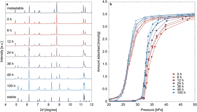
High-concentration reactants are essential for scale-up synthesis; however, ELM-11 obtained under high-concentration conditions exhibited less distinct gate opening than that produced under low-concentration conditions. This difference is likely due to variations in the phase of pre-ELM-11. Before addressing the issue of steepness, this section explores why metastable pre-ELM-11 forms at high reactant concentrations.While the previous section set the aging time after completing the dropwise addition of the bpy solution to 24 h, this section examines changes in particles during the aging process by sampling particles from the same batch synthesis. Fig. 2a displays the XRD patterns, which are dependent on aging time. At an aging time of 0 h (i.e., immediately after completing the addition of the bpy solution), the XRD pattern indicated that almost all of pre-ELM-11 was in its metastable phase. However, as aging progressed, peaks belonging to the stable phase emerged, with a decrease in the metastable phase's peak intensity. Although the peaks of the metastable phase were still clearly visible at 48 h after starting aging, an aging time of 100 h completely transformed pre-ELM-11 into its stable phase. Fig. 2b shows CO2 adsorption isotherms at 273 K for the ELM-11 particles corresponding to Fig. 2a. Both the adsorption and desorption branches exhibited a clear trend: the S-shaped curve became sharper with a longer aging time, strongly indicating a causal relationship between the phase of pre-ELM-11 and the steepness of gate adsorption.
As these characterization methods were conducted a sufficiently long time after the particles were sampled and filtered, the metastable-to-stable transformation of pre-ELM-11 occurs only in solvent. In fact, we confirmed that the particles obtained with an aging time of 24 h underwent transformation into the stable pre-ELM-11 upon re-immersing in a methanol–water solvent, as shown in Fig. S3, ESI.† That is, the phenomenon observed in high-concentration synthesis is the so-called solvent-mediated phase transformation.61,62 Two routes are considered in this transformation: framework rearrangement while remaining in the solid state or recrystallization of the stable phase with the dissolution of the metastable phase. Fig. 3 indicates that pre-ELM-11 follows the latter route. Fig. 3 displays the SEM images and particle size distributions (based on the longest side) of pre-ELM-11 with aging times of 0, 12, and 100 h. While certain amounts of particles over 30 μm exist at 0 h, their frequency decreases as aging progresses. Conversely, the frequency of particles around 20 μm increases at 12 h, and that of particles around 10 μm increases at 100 h. This observation cannot be explained by standard nucleation and growth theory or by Ostwald ripening, in which smaller particles are dissolved to aid the growth of larger particles. This indicates that, in the high-concentration synthesis of pre-ELM-11, larger particles in the metastable phase were first formed, followed by the dissolution of the metastable phase and growth of the stable phase.
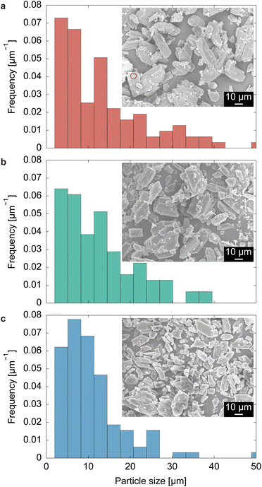 | ||
| Fig. 3 SEM images and particle size distributions of pre-ELM-11 with aging times of (a) 0 h, (b) 12 h, and (c) 100 h. The red circle in (a) indicates a supposed seed crystal of the stable phase. | ||
Fig. 4 schematically illustrates the mechanism of the solvent-mediated phase transformation of pre-ELM-11. The metastable structure, as the term implies, is less stable than the stable structure, meaning that the metastable structure dissolves more easily than the stable structure. Consequently, the solubility of the metastable phase is higher than that of the stable phase. Given that low-concentration synthesis mostly resulted in the stable phase of pre-ELM-11, the reactant concentrations of ([bpy], [Cu(BF4)2]) = (0.2 mol L−1, 0.1 mol L−1) likely occupy point E in Fig. 4a, which is between the solubility of the metastable phase (point A) and that of the stable phase (point C). Conditions in the area highlighted in yellow are supersaturated for the stable phase but not for the metastable phase, resulting in the nucleation and growth of only the stable phase. In contrast, high-concentration conditions with ([bpy], [Cu(BF4)2]) = (1.6 mol L−1, 0.8 mol L−1) place the system at point D in Fig. 4a, well above point A. The green highlighted area permits the nucleation and growth of both stable and metastable phases; however, according to Ostwald's law of stages, the metastable phase is more likely to form initially.61,62 Therefore, the early stage in high-concentration synthesis (point A) contains metastable pre-ELM-11 that has finished growing, along with seeds of the stable pre-ELM-11, as illustrated in Fig. 4b. Possibly, the tiny submicron fragments seen in Fig. 3a, one of which is highlighted with a red circle, are the stable seeds. As point A remains supersaturated for the stable state, the crystallization of the stable state proceeds with solute consumption, lowering the concentration below the solubility of the metastable state. This leads to the dissolution of the metastable pre-ELM-11 (point B), and ultimately, all the pre-ELM-11 reaches its stable phase after a prolonged aging time (point C).
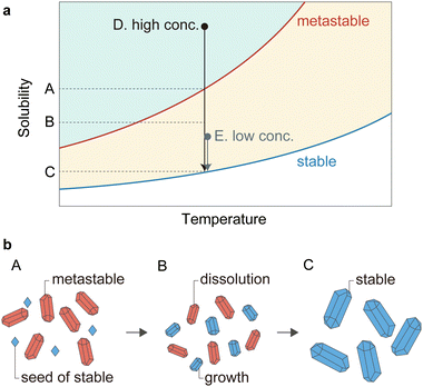 | ||
| Fig. 4 Schematics of the solvent-mediated phase transformation of pre-ELM-11 during the aging process: (a) solubility diagram and (b) illustrations of particle growth and dissolution. | ||
3.3 Mechanism of how the phase of pre-ELM-11 affects the steepness of gate opening
Although the mystery regarding the concentration-dependence of the two phases of pre-ELM-11 has been resolved, the relationship between the phase of pre-ELM-11 and the steepness of gate-opening behavior of the resultant ELM-11 remains an open question. There is a hypothesis that the steepness of the S-shaped curve represents the dispersity of particle sizes (specifically, the activation energy) in a sample used for the adsorption measurement.16,34–36 That is, the gate-opening pressure varies depending on the particle size, resulting in a smeared S-shape as a collection of step shapes, each with slightly different threshold pressures. However, this hypothesis may not apply to this study for two main reasons. First, although the metastable pre-ELM-11 (with an aging time of 0 h) and stable pre-ELM-11 (with an aging time of 100 h) differ in average size—13.4 μm and 10.9 μm, respectively—the particle size's impact on gate-opening pressure is often observed for particles under the submicron scale;16 particles on the order of 10 μm would be large enough that the particle surface's impact becomes negligible. Second, even if the gate-opening pressure of ELM-11 was influenced by particle size, given that metastable pre-ELM-11 has a distribution in a larger particle range, the resultant S-shaped curve would be smeared in the direction of lower pressure than the gate-opening pressure of the stable-derived ELM-11. This is because the ELM-11 nanosheet was reported to exhibit a higher gate-opening pressure;68 namely, ELM-11 follows the first of the two size effect trends discussed in the Introduction. This conflicts with the observations shown in Fig. 3, suggesting that factors other than particle size must contribute to the difference in the steepness of the S-shaped curve.Recently, another implication regarding the steepness of the S-shaped curve was elucidated through the derivation of the STA equation.63 Specifically, the parameter s in eqn (1), which controls the steepness of the S-shaped isotherm, represents the domain size within which the framework of a flexible MOF undergoes cooperative deformation upon gate opening. The values of s obtained by fitting the STA equation to the adsorption isotherm shown in Fig. 2b were 24.4 and 52.3 for aging times of 12 and 100 h, respectively (see Fig. S4, ESI†). This physically indicates that approximately 24 monomer units (Cu(bpy)2(BF4)2) deform cooperatively in the metastable-derived ELM-11, whereas 52 monomer units do so in the stable-derived ELM-11. Given that the Cu–bpy–Cu length of ELM-11 is about 1.1 nm, the domain sizes of the metastable- and stable-derived ELM-11 are estimated to be 5.4 and 8.0 nm, respectively, when considering a square-shaped domain.
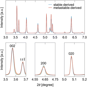
From the perspective of the STA equation, which posits that the steepness of the S-shaped curve reflects the domain size allowing for the cooperative motion of frameworks, it becomes more logical to attribute the difference in steepness to the crystallite size rather than the particle size, because boundaries between crystallites would limit cooperative deformations. Fig. 5 displays the XRD patterns of ELM-11 derived under metastable-rich conditions (with an aging time of 12 h) and stable conditions (with an aging time of 100 h), highlighting broader peaks for the metastable-derived ELM-11 than those for the stable-derived ELM-11. According to the Scherrer equation (eqn (3)), we calculated D200, D020, and D002 to be 71 nm, >1 μm, and 140 nm for the metastable-derived ELM-11, whereas they were 144 nm, >1 μm, and 209 nm for the stable-derived ELM-11, respectively. This demonstrates that the crystallite thickness along the a and c axes of the conventional cell of ELM-11 in its closed phase differs by roughly twice as much between the metastable- and stable-derived ELM-11. Intriguingly, the crystallite thickness along the b axis remains consistent and large, reflecting the framework structures of pre-ELM-11 and ELM-11, as discussed below.
The proposed mechanism explaining how the phase of pre-ELM-11 affects the steepness of gate opening is illustrated in Fig. 6 (also, refer to Fig. 1c, d and g for the atomic representation of the framework structures). In pre-ELM-11 structures, a Cu ion is coordinated by six bonds: two with BF4, two with bpy, and two with H2O, which in turn form hydrogen bonds with other bpy molecules. Essentially, pre-ELM-11 comprises one-dimensional (1D) chains made up of Cu(bpy)(BF4)2(H2O)2, which are loosely connected via hydrogen bonds between H2O and bpy. For the transition from pre-ELM-11 to ELM-11, the water molecules located between Cu ions and bpy need to be removed, potentially leading to a decrease in crystallinity. Stable pre-ELM-11 and ELM-11 structures exhibit a zigzag arrangement of square grids composed of bpy, in contrast to the straight arrangement found in metastable pre-ELM-11. This geometric similarity and dissimilarity can influence the crystallite size of the resulting ELM-11. Specifically, a zigzag-to-zigzag transformation can occur through minor movements of components to form new Cu–bpy bonds after the elimination of H2O molecules, whereas a straight-to-zigzag transformation involves significant rearrangements, including the major displacement of 1D chains or the formation of new Cu–bpy bonds not initially connected by H2O molecules. Such significant rearrangements in the metastable pre-ELM-11 can lead to disorders and defects in the resultant ELM-11 structure, resulting in a smaller crystallite size compared to that derived from the stable pre-ELM-11. These disorders are likely found around the bpy linking the 1D chains, indicating that the long periodicity along the chains is preserved. Hence, the crystallite thickness along the b axis, corresponding to the orientation of the 1D chains (see Fig. S5, ESI†), remained consistent regardless of the pre-ELM-11 phases. These crystallite sizes along axes other than the b axis of metastable-derived ELM-11 were roughly half that of stable-derived ELM-11 (e.g., 71 and 144 nm for D200, respectively). The reduced crystallite size in metastable-derived ELM-11 potentially limits the domain size over which the framework deforms cooperatively, resulting in a wider gate opening compared to that in the stable-derived ELM-11 according to the STA equation. However, it should be noted that while the s parameter obtained from the adsorption isotherm fitting also differed by almost twofold between the metastable- and stable-derived ELM-11 (24.4 and 52.3), their estimated square-shaped domain sizes (5.4 and 8.0 nm) were an order of magnitude smaller than their crystallite sizes. Assuming that the domain size should essentially match the crystallite size, this discrepancy may arise from a theoretical mismatch between the STA equation and the observations: specifically, while the STA equation is derived based on thermal equilibrium, the experimental adsorption isotherm reflects a non-equilibrium transition accompanied by hysteresis behavior. Although this deviation needs to be clarified through further research on the size effect of gate-opening behavior, it is plausible to assume that the crystallite size has a positive correlation with the domain size. Therefore, we can qualitatively conclude that the difference in the steepness of gate-opening behavior between metastable- and stable-derived ELM-11 stems from the variance in crystallite size.
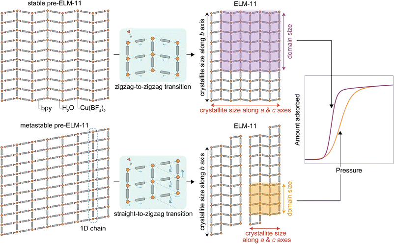 | ||
| Fig. 6 Schematic illustrating why the phase of pre-ELM-11 affects the steepness of the S-shaped isotherm upon gate opening on ELM-11. | ||
3.4 Synthesizing stable pre-ELM-11 with a short aging time
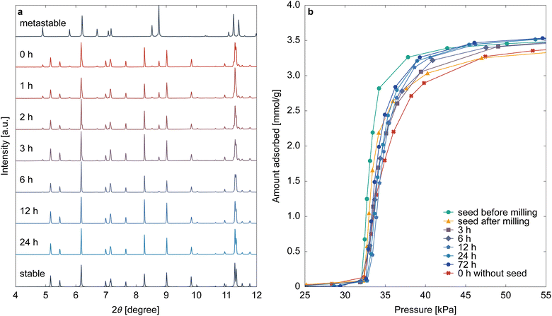
Considering the findings from previous sections, converting all pre-ELM-11 into its stable phase is the key to obtaining high-quality ELM-11. However, the solvent-mediated phase transformation of pre-ELM-11 into its stable form typically requires over 2 days, presenting a bottleneck in industrial production. This transformation involves the dissolution of the metastable phase and the crystallization of the stable phase. If the latter process is rate-limiting, preliminarily adding seeds of the stable phase can expedite the transformation.Fig. 7 displays the aging time dependencies of the XRD pattern of pre-ELM-11 and the CO2 adsorption isotherm on ELM-11 at 273 K, resulting from the addition of stable seeds prepared by high-concentration synthesis with sufficient aging time and subsequent milling (see Section 2.2). Unlike the seedless synthesis (Fig. 2), we observed that most pre-ELM-11 rapidly transitioned to its stable phase in the early stages of aging, completing the transformation within 12 h. This confirms that the crystallization of the stable phase is indeed the rate-limiting step in the solvent-mediated phase transformation of pre-ELM-11 and that the synthesis time can be reduced fourfold or more by adding seeds. The adsorption isotherms after 12 h of aging showed little change, indicating that the stable phase had fully formed; however, they exhibited a slightly wider S-shaped curve compared to the particles used to prepare the seeds (depicted by the green line in Fig. 7b). This discrepancy likely arises from damage inflicted on the seeds during milling, as apparent in the adsorption isotherm of milled seeds (the yellow line in Fig. 7b), both in the wider S-shaped curve and the reduced saturated adsorption amount. In seed-added synthesis, the pre-ELM-11 particles form around these damaged seeds, resulting in a smaller crystallite size compared to no-seed synthesis. This suggests that careful seed preparation is crucial for maximizing ELM-11 performance. Ideally, seeds should be synthesized as small particles without pulverization, possibly through low-temperature synthesis. Nonetheless, it is worth noting that even the synthesis method employing crushed seed crystals demonstrated sharper gate adsorption compared to metastable-derived ELM-11 (the red line in Fig. 7b). Given its abbreviated synthesis time, the seed addition method remains a highly valuable approach for synthesizing ELM-11 with pronounced gate opening.
4 Conclusions
This study elucidates the intricate relationship between the synthesis conditions of pre-ELM-11, a precursor to ELM-11, and the resultant MOF's structural and functional properties. Through meticulous experimentation and analysis, we have demonstrated that the phase of pre-ELM-11—whether stable or metastable—significantly influences the steepness of the gate-opening behavior of the resulting ELM-11. This is a critical factor for its potential applications in gas storage, separation, and sensing technologies.The key findings of our research can be summarized as follows:
(1) High-concentration synthesis conditions favor the formation of a metastable phase of pre-ELM-11, which can be transformed into its stable phase through extended aging in a solvent-mediated phase transformation process. This transformation is crucial for achieving the desired steepness in the gate-opening behavior of ELM-11.
(2) The phase of pre-ELM-11 affects the crystallite size of the resulting ELM-11, with the stable phase leading to larger crystallite sizes due to its structural similarity to ELM-11. This, in turn, influences the cooperative deformation domain size within the framework structure, directly impacting the steepness of the gate-opening behavior, as suggested in the derivation of the STA equation.
(3) The introduction of seeds of the stable phase of pre-ELM-11 during synthesis can significantly reduce the aging time required for solvent-mediated phase transformation, offering a practical approach to expedite the production of high-quality ELM-11. However, the preparation and handling of these seeds are critical to preserving the structural integrity and functional performance of the final product.
Considering the fact that both stable and metastable as-synthesized phases result in the same activated structure, the pre-ELM-11 and ELM-11 systems might represent a rare case. However, uncovering such a complex synthesis mechanism in one of the most well-known flexible MOFs is significant because it suggests that similar phenomena could occur in the scale-up synthesis of all MOFs. Moreover, this also hints at the possibility of synthesizing superior flexible MOFs as structural isomers of existing MOFs by altering synthesis conditions.
The rare situation in the pre-ELM-11 and ELM-11 systems coincidentally enabled us to change the crystallite size independently of the particle size. The obtained results—that the crystallite size, rather than the particle size, is the key factor determining the steepness of the gate-opening behavior—provide valuable insights for further elucidating the mechanism of the adsorption-induced structural transition. It is worth noting that reorganizing previous studies on the size dependence of gate-opening behavior with respect to crystallite size will improve our understanding of this size effect.
Author contributions
Shotaro Hiraide: conceptualization, methodology, writing – original draft, visualization, and supervision. Keisuke Nishimoto: formal analysis, investigation, writing – review & editing, and visualization. Satoshi Watanabe: conceptualization, writing – review & editing, and supervision.Conflicts of interest
The authors declare no conflict of interest.Acknowledgements
We are grateful to Dr Kawaguchi, Mr Saitoh, and Mr Takeshi for their assistance with this work. This work was financially supported in part by a Grant-in-Aid for Challenging Research (Pioneering) (grant no. 21K18187) and a Grant-in-Aid for Scientific Research (B) (grant no. 23K23116). The synchrotron radiation experiments were performed at the BL02B2 and BL13XU beamlines of SPring-8 with the approval of the Japan Synchrotron Radiation Research Institute (JASRI) (proposal no. 2021B1526, 2023B1574, and 2023B1863).References
- O. M. Yaghi and H. Li, J. Am. Chem. Soc., 1995, 117, 10401–10402 CrossRef CAS.
- S. Kitagawa and M. Kondo, Bull. Chem. Soc. Jpn., 1998, 71, 1739–1753 CrossRef CAS.
- A. Schneemann, V. Bon, I. Schwedler, I. Senkovska, S. Kaskel and R. A. Fischer, Chem. Soc. Rev., 2014, 43, 6062–6096 RSC.
- S. Horike, S. Shimomura and S. Kitagawa, Nat. Chem., 2009, 1, 695–704 CrossRef CAS PubMed.
- F. Bigdeli, C. T. Lollar, A. Morsali and H.-C. Zhou, Angew. Chem., Int. Ed., 2020, 59, 4652–4669 CrossRef CAS PubMed.
- S.-Q. Wang, S. Mukherjee and M. J. Zaworotko, Faraday Discuss., 2021, 231, 9–50 RSC.
- M. Taddei and C. Petit, Mol. Syst. Des. Eng., 2021, 6, 841–875 RSC.
- X. Yao, K. E. Cordova and Y.-B. Zhang, Small Struct., 2022, 3, 2100209 CrossRef CAS.
- K. Chen, S. H. Mousavi, R. Singh, R. Q. Snurr, G. Li and P. A. Webley, Chem. Soc. Rev., 2022, 51, 1139–1166 RSC.
- J. Troyano and D. Maspoch, Chem. Commun., 2023, 59, 1744–1756 RSC.
- T. A. Makal, A. A. Yakovenko and H.-C. Zhou, J. Phys. Chem. Lett., 2011, 2, 1682–1689 CrossRef CAS.
- M. Eddaoudi, J. Kim, N. Rosi, D. Vodak, J. Wachter, M. O'Keeffe and O. M. Yaghi, Science, 2002, 295, 469–472 CrossRef CAS PubMed.
- F. Carson, J. Su, A. E. Platero-Prats, W. Wan, Y. Yun, L. Samain and X. Zou, Cryst. Growth Des., 2013, 13, 5036–5044 CrossRef CAS.
- A. Kondo, H. Kajiro, H. Noguchi, L. Carlucci, D. M. Proserpio, G. Ciani, K. Kato, M. Takata, H. Seki, M. Sakamoto, Y. Hattori, F. Okino, K. Maeda, T. Ohba, K. Kaneko and H. Kanoh, J. Am. Chem. Soc., 2011, 133, 10512–10522 CrossRef CAS PubMed.
- H. Huang, H. Sato, J. Pirillo, Y. Hijikata, Y. S. Zhao, S. Z. D. Cheng and T. Aida, J. Am. Chem. Soc., 2021, 143, 15319–15325 CrossRef CAS PubMed.
- S. Ehrling, H. Miura, I. Senkovska and S. Kaskel, Trends Chem., 2021, 3, 291–304 CrossRef CAS.
- F.-X. Coudert, M. Jeffroy, A. H. Fuchs, A. Boutin and C. Mellot-Draznieks, J. Am. Chem. Soc., 2008, 130, 14294–14302 CrossRef CAS PubMed.
- Y. Sakata, S. Furukawa, M. Kondo, K. Hirai, N. Horike, Y. Takashima, H. Uehara, N. Louvain, M. Meilikhov, T. Tsuruoka, S. Isoda, W. Kosaka, O. Sakata and S. Kitagawa, Science, 2013, 339, 193–196 CrossRef CAS PubMed.
- C. Zhang, J. A. Gee, D. S. Sholl and R. P. Lively, J. Phys. Chem. C, 2014, 118, 20727–20733 CrossRef CAS.
- S. Watanabe, S. Ohsaki, T. Hanafusa, K. Takada, H. Tanaka, K. Mae and M. T. Miyahara, Chem. Eng. J., 2017, 313, 724–733 CrossRef CAS.
- S. Ehrling, I. Senkovska, V. Bon, J. D. Evans, P. Petkov, Y. Krupskaya, V. Kataev, T. Wulf, A. Krylov, A. Vtyurin, S. Krylova, S. Adichtchev, E. Slyusareva, M. S. Weiss, B. Büchner, T. Heine and S. Kaskel, J. Mater. Chem. A, 2019, 7, 21459–21475 RSC.
- X. Yang, H.-L. Zhou, C.-T. He, Z.-W. Mo, J.-W. Ye, X.-M. Chen and J.-P. Zhang, Research, 2019, 2019, 2019–9463719 CrossRef PubMed.
- S. Ohsaki, R. Nakazawa, A. Teranishi, H. Nakamura and S. Watano, Microporous Mesoporous Mater., 2020, 302, 110215 CrossRef CAS.
- S. Krause, F. S. Reuter, S. Ehrling, V. Bon, I. Senkovska, S. Kaskel and E. Brunner, Chem. Mater., 2020, 32, 4641–4650 CrossRef CAS PubMed.
- M. J. Thompson, C. L. Hobday, I. Senkovska, V. Bon, S. Ehrling, M. Maliuta, S. Kaskel and T. Düren, J. Mater. Chem. A, 2020, 8, 22703–22711 RSC.
- L. Abylgazina, I. Senkovska, S. Ehrling, V. Bon, P. St. Petkov, J. D. Evans, S. Krylova, A. Krylov and S. Kaskel, CrystEngComm, 2021, 23, 538–549 RSC.
- V. Bon, N. Busov, I. Senkovska, N. Bönisch, L. Abylgazina, A. Khadiev, D. Novikov and S. Kaskel, Chem. Commun., 2022, 58, 10492–10495 RSC.
- M. Maliuta, I. Senkovska, R. Thümmler, S. Ehrling, S. Becker, V. Romaka, V. Bon, J. D. Evans and S. Kaskel, Dalton Trans., 2023, 52, 2816–2824 RSC.
- S. Ohsaki, S. Watanabe, H. Tanaka and M. T. Miyahara, J. Phys. Chem. C, 2017, 121, 20366–20374 CrossRef CAS.
- S. M. J. Rogge, M. Waroquier and V. Van Speybroeck, Nat. Commun., 2019, 10, 4842 CrossRef PubMed.
- S. Vandenhaute, S. M. J. Rogge and V. Van Speybroeck, Front. Chem., 2021, 9, 718920 CrossRef CAS PubMed.
- S. M. J. Rogge, Faraday Discuss., 2021, 225, 271–285 RSC.
- K. Mitsumoto and K. Takae, Proc. Natl. Acad. Sci. U. S. A., 2023, 120, e2302561120 CrossRef CAS PubMed.
- V. Bon, N. Klein, I. Senkovska, A. Heerwig, J. Getzschmann, D. Wallacher, I. Zizak, M. Brzhezinskaya, U. Mueller and S. Kaskel, Phys. Chem. Chem. Phys., 2015, 17, 17471–17479 RSC.
- L. Abylgazina, I. Senkovska, R. Engemann, S. Ehrling, T. E. Gorelik, N. Kavoosi, U. Kaiser and S. Kaskel, Front. Chem., 2021, 9, 674566 CrossRef CAS PubMed.
- R. Bose, V. Bon, N. Bönisch, P. Selvam, N. S. Kaisare and S. Kaskel, Chem. Mater., 2023, 35, 7825–7838 CrossRef CAS.
- D. Li and K. Kaneko, Chem. Phys. Lett., 2001, 335, 50–56 CrossRef CAS.
- A. J. Blake, S. J. Hill, P. Hubberstey and W.-S. Li, J. Chem. Soc., Dalton Trans., 1997, 913–914 RSC.
- A. Kondo, H. Noguchi, S. Ohnishi, H. Kajiro, A. Tohdoh, Y. Hattori, W.-C. Xu, H. Tanaka, H. Kanoh and K. Kaneko, Nano Lett., 2006, 6, 2581–2584 CrossRef CAS PubMed.
- A. Kondo, N. Kojima, H. Kajiro, H. Noguchi, Y. Hattori, F. Okino, K. Maeda, T. Ohba, K. Kaneko and H. Kanoh, J. Phys. Chem. C, 2012, 116, 4157–4162 CrossRef CAS.
- J. Yang, Q. Yu, Q. Zhao, J. Liang, J. Dong and J. Li, Microporous Mesoporous Mater., 2012, 161, 154–159 CrossRef CAS.
- V. Bon, I. Senkovska, D. Wallacher, A. Heerwig, N. Klein, I. Zizak, R. Feyerherm, E. Dudzik and S. Kaskel, Microporous Mesoporous Mater., 2014, 188, 190–195 CrossRef CAS.
- H. Tanaka, S. Hiraide, A. Kondo and M. T. Miyahara, J. Phys. Chem. C, 2015, 119, 11533–11543 CrossRef CAS.
- S. Hiraide, H. Tanaka and M. T. Miyahara, Dalton Trans., 2016, 45, 4193–4202 RSC.
- M. Ichikawa, A. Kondo, H. Noguchi, N. Kojima, T. Ohba, H. Kajiro, Y. Hattori and H. Kanoh, Langmuir, 2016, 32, 9722–9726 CrossRef CAS PubMed.
- S. Hiraide, H. Tanaka, N. Ishikawa and M. T. Miyahara, ACS Appl. Mater. Interfaces, 2017, 9, 41066–41077 CrossRef CAS PubMed.
- F. J. Sotomayor and C. M. Lastoskie, Langmuir, 2017, 33, 11670–11678 CrossRef CAS PubMed.
- A. Kultaeva, V. Bon, M. S. Weiss, A. Pöppl and S. Kaskel, Inorg. Chem., 2018, 57, 11920–11929 CrossRef CAS PubMed.
- K. Ohazama, T. Ueda, K. Ukai, M. Ichikawa, H. Masu, H. Kajiro and H. Kanoh, Crystals, 2020, 10, 328 CrossRef CAS.
- A. Kondo, S. Noro, H. Kajiro and H. Kanoh, Coord. Chem. Rev., 2022, 471, 214728 CrossRef CAS.
- H. Sugiura, H. Kajiro and H. Kanoh, Colloids Surf., A, 2022, 651, 129745 CrossRef CAS.
- S. Hiraide, Y. Sakanaka, H. Kajiro, S. Kawaguchi, M. T. Miyahara and H. Tanaka, Nat. Commun., 2020, 11, 3867 CrossRef CAS PubMed.
- S. Hiraide, H. Arima, H. Tanaka and M. T. Miyahara, ACS Appl. Mater. Interfaces, 2021, 13, 30213–30223 CrossRef CAS PubMed.
- Y. Takakura, S. Sugimoto, J. Fujiki, H. Kajiro, T. Yajima and Y. Kawajiri, ACS Sustainable Chem. Eng., 2022, 10, 14935–14947 CrossRef CAS.
- J. Fujiki, H. Kajiro, Y. Takakura, T. Yajima and Y. Kawajiri, Chem. Eng. J., 2023, 460, 141781 CrossRef CAS.
- S. Sugimoto, Y. Takakura, H. Kajiro, J. Fujiki, H. Dashti, T. Yajima and Y. Kawajiri, J. Adv. Manuf. Process., 2023, 5, e10165 CrossRef CAS.
- Y. Sakanaka, S. Hiraide, I. Sugawara, H. Uematsu, S. Kawaguchi, M. T. Miyahara and S. Watanabe, Nat. Commun., 2023, 14, 6862 CrossRef CAS PubMed.
- H. Arima, S. Hiraide, M. T. Miyahara and S. Watanabe, ACS Appl. Mater. Interfaces, 2023, 15, 36975–36987 CrossRef CAS PubMed.
- R. Saitoh, S. Hiraide, M. T. Miyahara and S. Watanabe, J. Soc. Powder Technol., Jpn., 2023, 60, 594–599 CrossRef CAS.
- S. Watanabe, S. Hiraide, H. Kunimitsu, A. Fujiwara and M. T. Miyahara, Front. Mater., 2022, 9, 825592 CrossRef.
- P. Cardew and R. Davey, Proc. R. Soc. London, Ser. A, 1985, 398, 415–428 CAS.
- R. Davey, P. Cardew, D. McEwan, D. Sadler and J. Crystal, Growth, 1986, 79, 648–653 CrossRef CAS.
- S. Hiraide, Y. Sakanaka, Y. Iida, H. Arima, M. T. Miyahara and S. Watanabe, Proc. Natl. Acad. Sci. U. S. A., 2023, 120, e2305573120 CrossRef CAS PubMed.
- S. Kawaguchi, M. Takemoto, K. Osaka, E. Nishibori, C. Moriyoshi, Y. Kubota, Y. Kuroiwa and K. Sugimoto, Rev. Sci. Instrum., 2017, 88, 085111 CrossRef CAS PubMed.
- S. Kawaguchi, M. Takemoto, H. Tanaka, S. Hiraide, K. Sugimoto and Y. Kubota, J. Synchrotron Radiat., 2020, 27, 616–624 CrossRef CAS PubMed.
- S. Kawaguchi, S. Kobayashi, H. Yamada, H. Ashitani, M. Takemoto, Y. Imai, T. Hatsui, K. Sugimoto and O. Sakata, J. Synchrotron Radiat., 2024, 31 DOI:10.1107/s1600577524003539.
- D. Black, M. Mendenhall, A. Henins, J. Filliben and J. Cline, The Certification Of Standard Reference Material 660c For Powder Diffraction, Powder Diffr., 2020, 35(1) DOI:10.1017/s0885715620000068 , https://www.nist.gov/publications/certification-standard-reference-material-660c-powder-diffraction.
- T. Omiya, K. Sasaki, Y. Uchida and N. Nishiyama, ACS Appl. Nano Mater., 2018, 1, 3779–3784 CrossRef CAS.
Footnote |
| † Electronic supplementary information (ESI) available: SEM image of particles obtained through low-concentration synthesis. Thermogravimetric analysis of pre-ELM-11 particles. Results of re-immersion experiments. Fitting results of adsorption isotherms obtained using the STA equation. Visualization displaying the relationship between the layer structure of ELM-11 and its conventional cell. See DOI: https://doi.org/10.1039/d4ta02068e |
| This journal is © The Royal Society of Chemistry 2024 |

