
Construction of BaTiO3–TiO2 hollow sphere heterojunctions for enhanced microwave dynamic therapy in cancer treatment
Yaodong
Chen†
 *a,
Fangyu
Cai†
d,
Yadong
Liu
e,
Wenwen
Fan
a,
Jingjie
Wang
a,
Guolin
Yin
a,
Jiayi
Ren
a,
Jingwei
Cao
a,
Yongming
Fu
*c and
Jie
Chen
*b
*a,
Fangyu
Cai†
d,
Yadong
Liu
e,
Wenwen
Fan
a,
Jingjie
Wang
a,
Guolin
Yin
a,
Jiayi
Ren
a,
Jingwei
Cao
a,
Yongming
Fu
*c and
Jie
Chen
*b
aDepartment of Ultrasonic Imaging, First Hospital of Shanxi Medical University, Taiyuan, 030001, China. E-mail: chenyaodong@sxmu.edu.cn
bDepartment of Infection Diseases, First Hospital of Shanxi Medical University, Taiyuan, 030001, China. E-mail: chenjie-5@163.com
cSchool of Physics and Electronic Engineering, State Key Laboratory of Quantum Optics and Quantum Optics Devices, Institute of Laser Spectroscopy, Shanxi University, Taiyuan, 030006, China. E-mail: fuyongming@sxu.edu.cn
dDepartment of Thoracic Surgery, Harbin Medical University Cancer Hospital, Harbin, 150040, China
eState Key Laboratory of Ultrasound in Medicine and Engineering, Institute of Ultrasound Imaging, The Second Affiliated Hospital, Chongqing Medical University, Chongqing, 400010, China
First published on 20th April 2024
Abstract
Cancer is one of the primary health concerns among humans due to its high incidence rate and lack of effective treatment. Currently, medical techniques to achieve the precise elimination of local cancer lesions with negligible damage to normal tissues are still intensely desired. Herein, we synthesized BaTiO3–TiO2 hollow spheres (BTHSs) for use in microwave dynamic therapy (MWDT) for cancer. Under UV irradiation, BTHSs can mediate the production of multiple reactive oxygen species (ROS), mainly 1O2, which results in a rapid photocatalytic degradation rate (97%), 1.6-fold that of commercial P25. Importantly, the ROS production process can be triggered by microwaves to effectively execute MWDT for cancer. Under microwave irradiation, BTHSs exhibit a remarkable therapeutic effect and slight cytotoxicity. In terms of mechanism, the enhanced ROS production efficiency of BTHSs can be attributed to their unique hollow structure and the formation of a type-II heterojunction by the incorporation of BaTiO3. The hollow structure increases the availability of active sites and enhances light scattering, while the BaTiO3–TiO2 heterojunction enhances the photocatalytic activity of TiO2 through charge transfer and electron–hole separation. Overall, this study provides important insights into the design and optimization of sensitizers for MWDT applications.
1. Introduction
Cancer has emerged as a significant barrier to increasing life expectancy due to the rising rates of morbidity and mortality worldwide.1–3 Multiple therapeutic theories and technologies have been developed to achieve better treatment efficiency and prognosis.4–7 For neoplasms located deep in the viscera, such as hepatocellular carcinoma (HCC), ultrasonic imaging-guided microwave ablation therapy has become a prominent minimally invasive and safe procedure for tumor elimination.8–10 However, this procedure often leads to hyperthermia-induced side effects on important organs adjacent to the lesion undergoing ablation.11–13 Therefore, it is necessary to explore and develop novel treatment technologies to address these challenges.The formation and progression of tumors lead to a reprogramming of malignant cell metabolism, characterized by a shift toward aerobic glycolysis as the dominant energy supply mode. This alteration in metabolism results in an imbalance in redox homeostasis.14–16 Consequently, cytotoxic reactive oxygen species (ROS), including singlet oxygen (1O2), hydroxyl radicals (˙OH) and superoxide radicals (˙O2−), are generated as byproducts of molecular oxygen-based energy metabolism. Interestingly, ROS are preferentially generated and accumulated in tumor cells rather than in normal cells,17,18 resulting in a high basal ROS content in cancer cells that is prone to exceed the cytotoxic threshold.19–21 Exploiting this disparity, researchers have proposed the induction of additional ROS production as an effective and selective eradication strategy for neoplasms.22–24
Nanostructured TiO2 is widely recognized as an exceptional photosensitizer for ultraviolet (UV)-mediated photodynamic therapy (PDT) in cancer treatment due to its good biocompatibility and UV absorbance.25,26 Upon UV irradiation, electrons and holes are generated inside TiO2 nanoparticles, are transported to the surface, and react with molecular oxygen and chemisorbed water molecules to generate various cytotoxic ROS. In particular, the generation of ˙OH is an oxygen-independent process, making it highly promising for achieving cytotoxicity in hypoxic tumor microenvironments.27,28 However, the limited penetration ability of UV light significantly hinders efforts to broaden the application of PDT based on raw TiO2 nanomaterials.29
Recently, microwave dynamic therapy (MWDT), in which microwaves are employed in conjunction with designated nanomaterials to generate ROS, has been proposed for the ablation of neoplasms.30 Compared to PDT, MWDT utilizes minimally invasive electrodes commonly used in clinical microwave ablation to directly reach the interior of tumors and generate microwaves, which penetrate much deeper than light waves.31,32 A needle microwave electrode operated at low power can effectively stimulate the generation of plasma from tiny dissolved bubbles in liquids, emitting UV light to trigger ROS production from spherical TiO2 nanocatalysts.33–35 However, TiO2-based MWDT still suffers from certain drawbacks, such as the low separation of charge carriers.
Combining hollow structures and heterojunction configurations in TiO2 nanocomposites is a promising approach to improve the generation and separation of electron–hole pairs. TiO2 hollow structures (THSs) possess a large specific surface area and high light harvesting ability to enhance the photogeneration of charge carriers,36–38 while heterojunctions facilitate the separation and transfer of electron–hole pairs.39–49 Therefore, the development of hollow heterojunction structures has attracted considerable attention due to their synergistic advantages. BaTiO3–TiO2 hollow spheres (BTHSs) are representative examples of such structures. The bandgap of BaTiO3 is higher than that of TiO2, enabling the transfer of photogenerated electrons from TiO2 to BaTiO3 and inhibiting the recombination of photogenerated electron–hole pairs.50–52 In addition, the hollow spheres exhibit strong structural stability, excellent photocatalytic activity and biocompatibility, making them ideal candidates for various applications that depend on the generation of additional ROS, including MWDT.
In this study, we successfully synthesized BTHSs with a heterojunction structure to explore their potential application in MWDT. Photocatalytic experiments clearly demonstrated that these BTHSs can sufficiently increase the ROS production efficiency under UV irradiation, as determined by electron spin resonance (ESR) and trapping tests. Furthermore, the enhanced ROS production efficiency of BTHSs under microwave irradiation was also observed, demonstrating the good MWDT performance of these materials for killing cancer cells in vitro. The results suggest that BTHSs are promising nanoscale catalytic materials for MWDT-mediated cancer treatment.
2. Experimental methods
2.1 Synthesis of THSs
THSs were prepared by using a polystyrene (PS)-template solvothermal method. Typically, 200 mg of tetrabutyl titanate (TBOT) was dissolved in 15 mL of PS suspension (210 nm in diameter, 1 wt% in water) under vigorous stirring. Then, 1 mL of hydrochloric acid (38%) was added dropwise. Following stirring for 1 h, a reaction was conducted for 12 h in a Teflon-lined stainless-steel autoclave at 200 °C. Finally, the products were centrifuged, washed with ethanol/deionized water three times, and heated at 500 °C for 2 h.2.2 Synthesis of BTHSs
BTHSs were synthesized from the THSs by a facile hydrothermal method. Typically, 460 mg of Ba(OH)2·8H2O was dispersed in 50 mL of ethanol, diethylene glycol, and isopropanol with a volume ratio of 2![[thin space (1/6-em)]](https://www.rsc.org/images/entities/char_2009.gif) :2:1 under stirring, while 150 mg of tetrabutylammonium hydroxide was dissolved in 10 mL of deionized water in another beaker and subjected to ultrasonication. After mixing these two solutions, 200 mg of THSs were dispersed in the mixture under stirring for 30 min, and the mixture was sealed in a 100 mL Teflon-lined stainless-steel autoclave and heated at 170 °C for 4 h. Finally, the product was centrifugally washed with deionized water and ethanol 3 times and dried overnight at 80 °C. To investigate the effect of temperature and time on the synthesis of BTHSs, other samples were synthesized under the same conditions except for the heating temperature and time.
:2:1 under stirring, while 150 mg of tetrabutylammonium hydroxide was dissolved in 10 mL of deionized water in another beaker and subjected to ultrasonication. After mixing these two solutions, 200 mg of THSs were dispersed in the mixture under stirring for 30 min, and the mixture was sealed in a 100 mL Teflon-lined stainless-steel autoclave and heated at 170 °C for 4 h. Finally, the product was centrifugally washed with deionized water and ethanol 3 times and dried overnight at 80 °C. To investigate the effect of temperature and time on the synthesis of BTHSs, other samples were synthesized under the same conditions except for the heating temperature and time.
2.3 Characterization
The morphology and structure of the samples were characterized by scanning electron microscopy (SEM, Hitachi SU-8010) and transmission electron microscopy (TEM, JEOL JEM-2100F). The chemical states were determined by X-ray photoelectron spectroscopy (XPS, Thermo Kalpha). The crystal structure of the samples was analyzed by X-ray powder diffraction (XRD, Ultima IV) with a scan range of 10°–80°.2.4 Detection of UV-induced ROS
The total ROS generation induced by UV photocatalysis was evaluated by measuring the effectiveness of the generated ROS in the decomposition of methyl orange (MO) using photochemical reaction apparatus (PL-03, Changzhou Hongming Co., Ltd.). Specifically, 10 mg of BTHSs were dispersed in 50 mL of MO aqueous solution (10 mg L−1). The suspension was vigorously stirred in the dark for 2 h to establish an adsorption/desorption equilibrium between the dye and the nanoparticles. Then, the suspension was irradiated with a 300 W mercury lamp, and 0.5 mL of the solution was removed at 5 min intervals. The concentration of MO was determined at 464 nm using a UV–Vis spectrophotometer (MAPADA M4). The degradation efficiency was calculated by C/C0, where C and C0 represent the MO concentration at the beginning and during the reaction, respectively. To investigate the main active species involved in photocatalytic reactions, excess p-benzoquinone (BQ), isopropanol (IPA), and triethylene diamine (DABCO) were separately added as scavengers for ˙O2−, ˙OH and 1O2, respectively. The photocatalytic degradation efficiencies of the THSs and BTHSs were compared after adding free radical scavengers to determine the involved active species.2.5 Detection of MWDT-induced ROS
1,3-Diphenylisobenzofuran (DPBF, 400 μL, 1 mg mL−1) or methylene blue (MB, 1 mL, 0.1 mg mL−1) was added to the nanoparticles suspended in deionized water (50 mL, 1 mg mL−1). The suspension was vigorously stirred in the dark for 2 h to establish an adsorption/desorption equilibrium between the dye and the nanoparticles. Then, 0.5 mL of the above mixture was added to an EP tube with a maximum capacity of 1.5 mL. Subsequently, the samples were irradiated using a needle microwave probe for 30 min under 10 W power using microwave emission equipment at 2450 MHz (WB-3100AI, Baoxing Medical, China) on ice. After centrifugation, the concentrations of DPBF and MB were determined as described above for MO except that the detection wavelengths were 410 nm and 665 nm, respectively.2.6 Cell culture
The representative cancer cell line HepG2 (HCC cells) was supplied by the Cell Bank of Type Culture Collection of the Chinese Academy of Sciences (Shanghai, China). The culture medium for HepG2 cells was prepared by supplementing DMEM with fetal bovine serum and penicillin–streptomycin reagent in a sterile environment. A humidified incubator containing 5% CO2 was set to 37 °C.2.7 MTT assay
HepG2 cells were incubated with different doses of THSs or BTHSs for 24 h in a 96-well plate. To detect cell viability, a standard MTT assay was performed. Briefly, the tested cells were sequentially subjected to 4 h of incubation with MTT, dissolution with DMSO, and measurement of the absorbance at 490 nm. For the MWDT experiments, the HepG2 cells were incubated with THSs or BTHSs for 24 h, followed by microwave irradiation, 3 h of incubation and MTT detection.2.8 ROS detection in cancer cells
HepG2 cells were incubated with THSs or BTHSs for 24 h in a 48-well plate. Subsequently, the cells were washed twice with PBS and incubated with a DCFH-DA probe (300 μL, 10 μmol L−1) for 20 min. Then, microwave irradiation was conducted on ice, and the visualized fluorescence intensity reflecting intracellular ROS production was imaged by means of a fluorescence microscope (BX53, Olympus) after washing with PBS.2.9 Calcein AM/PI staining
HepG2 cells were incubated with THSs or BTHSs for 24 h in a 48-well plate. Subsequently, the cells were irradiated with microwaves on ice after washing twice with PBS. After 3 h, the cells were incubated with 300 μL calcein AM/PI reagent for 30 min in the dark. The survival status of the cells was visually determined by means of a fluorescence microscope after washing with PBS.2.10 Statistical analysis
One-way ANOVA was implemented using SPSS 23.0 software, which is designed for the statistical analysis of data collected from multiple groups (>2). In addition, the recognized statistically significant threshold was set as P < 0.05.3. Results and discussion
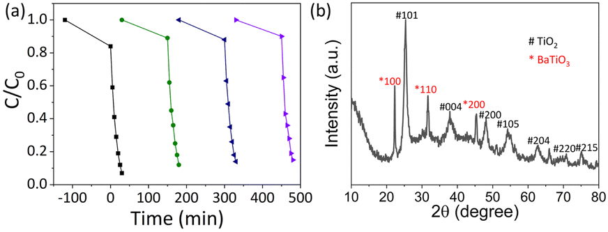
The EDS spectra show that the THS sample consisted of only Ti and O, and Ba was successfully incorporated without the introduction of other impurities in the BTHS sample (Fig. 1a). The XRD pattern of the BTHSs shows the coexistence of BaTiO3 and anatase TiO2 phases (Fig. 1b). The diffraction peaks at 25.18°, 38.02°, 47.96°, 54.60°, 62.72°, 70.39°, 74.98°, and 82.74° correspond to the (101), (004), (200), (105), (204), (220), (215), and (224) planes of anatase TiO2 (PDF card No. 98-001-0081), while the diffraction peaks at 22.27°, 32.02°, and 44.87° correspond to the (100), (110), and (200) planes of BaTiO3 (PDF card No. 01-075-1606), respectively. These results indicate that a portion of TiO2 crystals was calcified to form BaTiO3–TiO2 nanocomposites. | ||
| Fig. 1 (a) EDS spectra. (b) XRD patterns. (c) SEM image of THSs. (d) SEM image of BTHSs. (e) TEM image of BTHSs. (f) High-resolution TEM image. (g)–(i) Elemental mapping profiles of (g) O, (h) Ba, and (i) Ti. | ||
Fig. 1c shows the SEM image of THSs, indicating that the hollow spheres exhibited a uniform size distribution with an average diameter of approximately 240 nm. After forming BaTiO3, the average diameter did not significantly increase, but the surface became rougher (Fig. 1d). The TEM image of the BTHSs further confirmed the hollow structure of the spheres with a wall thickness of ∼30 nm (Fig. 1e). In the high-resolution TEM image, lattice spacings of 0.23 nm and 0.32 nm corresponding to the (111) plane of BaTiO3 and (110) plane of TiO2, respectively, were observed (Fig. 1f). The selected electron diffraction (SAED) pattern indicated that the BTHSs were polycrystalline (inset of Fig. 1f). As seen from the elemental mapping profiles in Fig. 1g–i, Ti, Ba, and O were uniformly distributed in the 30-nm-thick shell of a BTHS.
The chemical compositions of the THSs and BTHSs were analyzed by XPS. The survey spectrum shows the presence of Ba, Ti, O and C in the BTHSs, with C originating from environmental sources (Fig. 2a). The high-resolution Ti 2p, O 1s and Ba 3d spectra are presented in Fig. 2b–d, respectively. In Fig. 2b, the Ti 2p spectrum of the BTHSs shows two peaks at 458.6 and 464.0 eV, corresponding to Ti 2p3/2 and Ti 2p1/2, respectively. In comparison to the those of the TiO2 sample, the peak positions of Ti 2p states experience a slight shift toward lower energy, indicating the coexistence of TiO2 and BaTiO3.53 In Fig. 2c, the O 1s spectrum of TiO2 exhibits two peaks at 529.7 and 531.9 eV, representing Ti–O bonds and oxygen vacancies, respectively. For the BTHSs, the peak assigned to lattice oxygen shifts considerably to 529.0 eV, which is attributed to Ba–O bonds. The Ba 3d spectrum in Fig. 2d exhibits two prominent peaks at 780.2 and 796.2 eV, corresponding to Ba 3d5/2 and Ba 3d3/2, respectively. These results confirm the successful formation of the BaTiO3–TiO2 heterojunction.
 | ||
| Fig. 2 XPS spectra of THSs and BTHSs. (a) Survey spectrum. (b) Ti 2p. (c) O 1s. (d) Ba 3d. | ||
The PL spectra of THSs and BTHSs are shown in Fig. 3a. The strong peak at 400 nm corresponds to the intrinsic emission of TiO2, while the broad peak in the range of 500–700 nm corresponds to defect-related emissions. Upon heterojunction formation with BaTiO3, the intensity of the intrinsic emission significantly decreases, which can be attributed to the spatial separation of hole–electron pairs enhanced by the effective charge transfer between TiO2 and BaTiO3. Fig. 3b presents the transient photocurrent curves. It can be observed that the photocurrent of BTHSs is three times higher than that of THSs under the same conditions, indicating superior charge separation efficiency in BTHSs.
 | ||
| Fig. 3 Photoelectric properties of THSs and BTHSs. (a) PL spectra. (b) Photocurrent behaviors. | ||
The photocatalytic ROS production of THSs and BTHSs was compared by evaluating the photocatalytic degradation efficiency of MO (Fig. 4a). Upon exposure to UV illumination, MO was barely degraded without any catalysts. When commercial P25 was used as a photocatalyst, the MO concentration decreased to ∼57% of its initial value after 30 min, confirming the efficient catalytic activity of TiO2. The synthesized THSs achieved an even lower MO concentration, reaching ∼21%. The BTHSs exhibited the highest efficiency for degrading MO, with a degradation rate of ∼93%. The photocatalytic degradation kinetics of the samples followed a quasi-first-order reaction equation, as shown in Fig. 4b. Notably, the reaction rate constant of the BTHSs was more than twice that of the THSs. The photocatalytic degradation performance of the samples synthesized under different heating temperatures and times is presented in Fig. 4c and d, respectively, displaying that the optimal synthesis conditions were heating at 170 °C for 4 h.
 | ||
| Fig. 4 (a) Photocatalytic degradation processes of different catalysts. (b) The corresponding reaction kinetic curves. (c) Photocatalytic degradation processes of BTHSs synthesized at different temperatures for 4 h. (d) Photocatalytic degradation processes of BTHSs synthesized at 170 °C for different times. | ||
To assess the stability of BTHSs, the photocatalytic process is repeated, as shown in Fig. 5a. After four cycles of catalytic degradation of MO, the degradation rate of photocatalysts remained at 85%. Afterwards, the BTHSs are subjected to centrifugation and drying processes and analyzed by XRD, as shown in Fig. 5b. Compared to the XRD pattern of initial BTHSs, no discernible changes can be observed, exhibiting a favorable level of stability of BTHSs.
 | ||
| Fig. 5 Stability of BTHSs. (a) Repeat test. (b) XRD pattern of BTHSs after the reaction. | ||
To investigate the role of reactive radicals in the photocatalytic activity of THSs and BTHSs, the photoinduced generation of three representative ROS (1O2, ˙OH and ˙O2−) was tested by electron spin resonance (ESR) (Fig. 6a–c). The BTHSs generated significantly more radicals than the THSs. To study the contribution of each ROS, the ROS were selectively quenched using their corresponding scavengers (Fig. 6d). The addition of each type of ROS scavenger led to a decrease in photocatalytic activity to varying degrees for both THSs and BTHSs. The most severe inhibition of the catalytic activity was observed when a singlet oxygen scavenger was added. The dominant inhibitory effect of the singlet oxygen scavenger on both THS and BTHS photocatalysts suggests that the generation of singlet oxygen is the key factor in the degradation of MO. This work provides an improved understanding of the mechanism of BTHS-mediated photocatalytic ROS production.
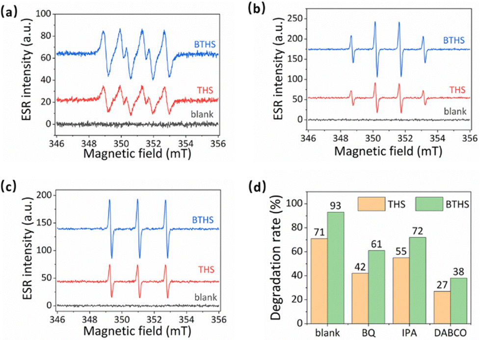 | ||
| Fig. 6 (a)–(c) ESR signals of (a) superoxide radicals, (b) hydroxyl radicals, and (c) singlet oxygen catalyzed by THSs and BTHSs. (d) The radical scavenger tests. | ||
To reveal the detailed photocatalytic mechanism, the band alignment structure of the TiO2/BaTiO3 heterojunction is determined, as shown in Fig. 7. Fig. 7a shows the DRS spectra of TiO2/BaTiO3, revealing their absorption ranges in the ultraviolet region. Fig. 7b presents the corresponding Tauc plots, where the band gaps (Eg) of TiO2 and BaTiO3 are determined to be 3.11 and 2.95 eV, respectively. The measured band gap values are slightly smaller compared to standard crystals, which can be attributed to the presence of abundant defects during the hydrothermal synthesis process. Fig. 7c displays the VB-XPS spectra, confirming that the valence band (VB) values of TiO2 and BaTiO3 are 2.88 and 2.56 eV, respectively, indicating that the VB of TiO2 is more positive than BaTiO3. Mott–Schottky curves of TiO2 and BaTiO3 under different frequencies are shown in Fig. 7d and e, respectively. The positive slope of the curves indicates that both TiO2 and BaTiO3 are n-type semiconductors. By the intersection of the tangent line of the M–S curves and the x-axis, the flat band potentials of TiO2 and BaTiO3 are determined to be –0.11 and –0.23 V, respectively, indicating a more negative conduction band (CB) position of BaTiO3 compared to TiO2. Based on these results, TiO2 and BaTiO3 can form type-II heterojunction, as shown in Fig. 7f. The excellent UV photocatalytic performance of BTHSs was attributed to the synergistic effect of their hollow structure and heterojunction. The unique energy band structure of the heterojunction plays a crucial role in enhancing the photocatalytic activity by promoting the generation of free radicals. Specifically, the BaTiO3/TiO2 heterojunction possesses a bandgap structure that enables efficient photoinduced charge separation.54 The VB value of TiO2 is positioned higher than that of BaTiO3, allowing the extraction of electrons from the CB of BaTiO3.55 This leads to the accumulation of holes on the CB of BaTiO3. Consequently, the recombination rate of photogenerated electron–hole pairs is effectively suppressed. Furthermore, an interface junction is formed at the interface between BaTiO3 and TiO2, facilitating the transfer of holes from the CB of BaTiO3 to TiO2. This process contributes to the enhanced generation of free radicals.56 Additionally, the hollow internal structure of BTHSs enhances light absorption, and the thin shell reduces the electron migration distance, which promotes efficient carrier separation and transfer.57 Therefore, by utilizing the unique energy band structure and hollow structure of BTHSs, the photocatalytic activity can be significantly improved, and the generation of free radicals can be effectively increased.
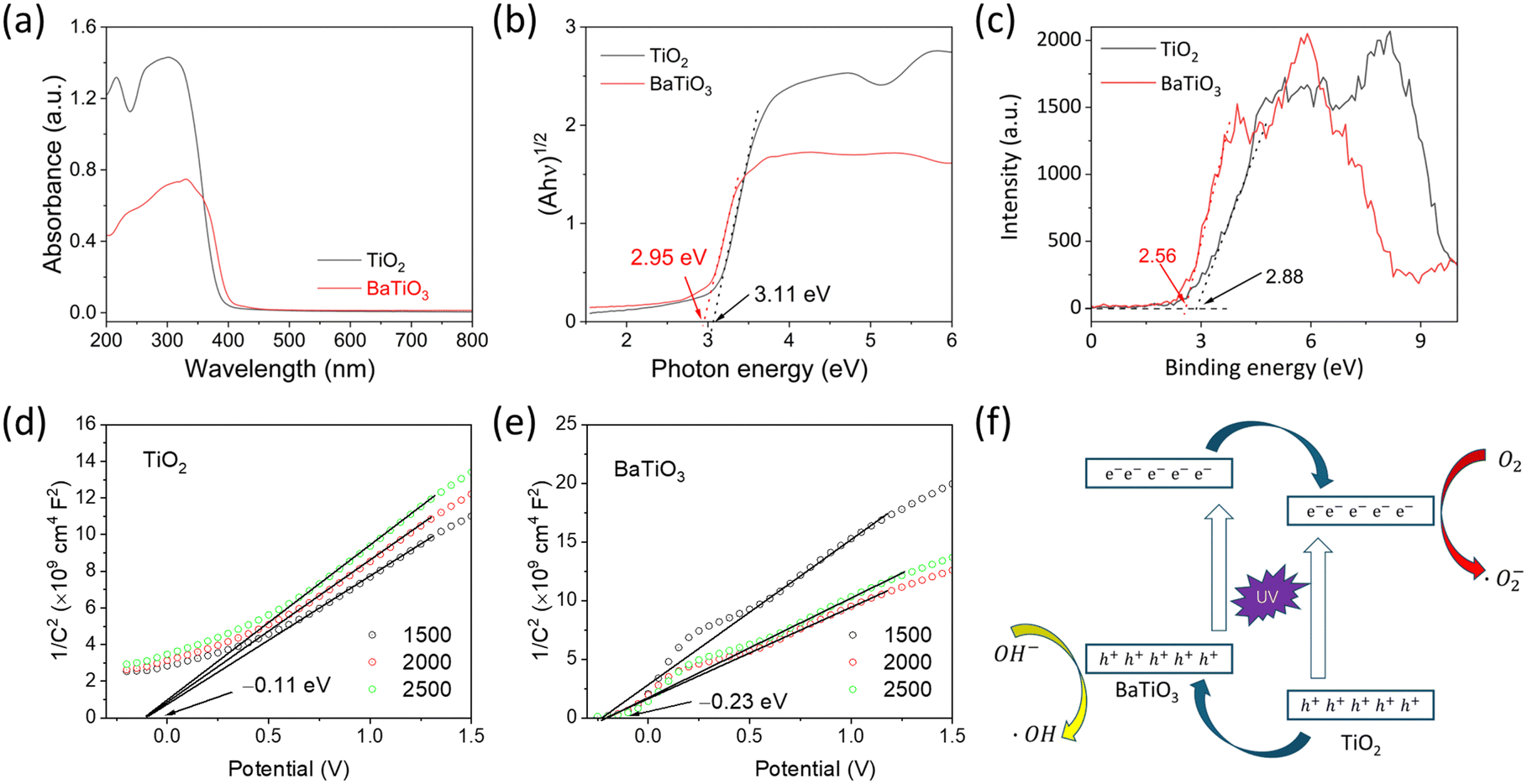 | ||
| Fig. 7 The photocatalytic mechanism of BTHSs. (a) DRS spectra. (b) Tauc plots. (c) VB-XPS spectra. (d) Mott–Schottky curves of TiO2. (e) Mott–Schottky curves of BaTiO3. (f) Detailed band alignment structure of the TiO2/BaTiO3 heterojunction. | ||
Based on the preeminent performance of BTHSs and THSs in UV-induced ROS generation, we investigated whether this procedure can be activated by microwave irradiation to produce ROS with significant cytotoxicity, such as 1O2 and ˙OH. Therefore, the capability of BTHSs and THSs to catalyze ROS production under microwave irradiation was detected using DPBF and MB degradation efficiency. DPBF is widely believed to be mainly degraded by 1O2, while MB mainly undergoes degradation reactions with ˙OH.58–60 The results indicate that microwave irradiation alone was unable to cause significant degradation of DPBF or MB. Under microwave irradiation, THSs and BTHSs catalyzed the remarkable degradation of DPBF and MB, while the catalytic degradation effect of P25 was weaker (Fig. 8a and b). This phenomenon could be attributed to the benefits of the hollow cavity, which increased the utilization rate of UV by enhancing the UV harvest through its high specific surface area and multiple reflections within the interior cavity. In addition, BTHSs exhibited better catalytic performance with regard to microwave-induced ROS production than THSs. This disparity could be illustrated by the presence of the BaTiO3–TiO2 heterojunction, which facilitates the separation and transfer of generated charge carriers. Overall, the existence of hollow structures and heterojunctions markedly improves the catalytic capacity of TiO2 nanoparticles, making BTHSs an excellent candidate nanomaterial for MWDT.
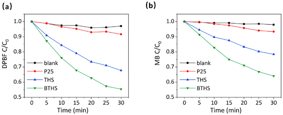 | ||
| Fig. 8 The degradation performances of (a) DPBF and (b) MB under MWDT. | ||
Then, we further investigated whether these two nanoparticles could produce ROS in cancer cells and exert MWDT effects. First, we demonstrated that BTHSs or THSs alone had no notable cytotoxicity in HepG2 cells (Fig. 9a). After combined intervention with microwave irradiation and BTHS/THS incubation, enormous ROS production was detected in HepG2 cells, and ROS levels were higher in the BTHS + MW group than in the THS + MW group. However, no obvious ROS generation was detected in the other groups (Fig. 9b). Subsequently, calcein AM/PI staining was employed to observe the survival or death of HepG2 cells. The results showed that the mortality rate of HepG2 cells was positively correlated with the ROS level, and the largest amount of cell death was observed in the BTHS + MW group (Fig. 9c). Next, MTT assays quantitatively validated this result (Fig. 9d). It should be noted that although BaTiO3 nanomaterials exhibit excellent biocompatibility and non-toxicity in biological therapeutic applications,61–63 the degradation and discharge of nanomaterials remain important challenges for the application of inorganic nanomaterials in tumors. Typically, surface modification with targeting moieties is employed to enhance the accumulation of nanomaterials at tumor sites and facilitate their excretion through urine or feces, thereby reducing the adverse effects on normal tissues.64,65 In future studies, we will further improve the design of nanomaterials to make them more suitable for clinical applications.
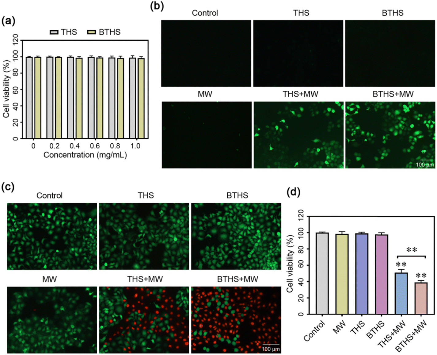 | ||
| Fig. 9 (a) Cytotoxicity assays of THSs and BTHSs in cancer cells. (b) Intracellular ROS detection after THS- or BTHS-mediated MWDT. (c) The therapeutic effect of THS or BTHS-mediated MWDT in cancer cells detected by calcein AM/PI staining and (d) MTT assays. MW: microwave irradiation. ** P < 0.01. | ||
4. Conclusions
In summary, hollow-structured BaTiO3–TiO2 heterojunctions are successfully synthesized for MWDT. Under UV irradiation, BTHSs can effectively generate multiple ROS, mainly composed of 1O2, which can be triggered by microwaves to implement effective MWDT for cancer. The enhanced catalytic ROS production performance of BTHSs can be attributed to their unique hollow structure and BaTiO3–TiO2 heterojunction, which increased the utilization rate of UV as well as facilitated the separation and transfer of generated charge carriers, making BTHSs an excellent nanomaterial for mediating MWDT. Although the mechanism of MWDT still needs further investigation, this study provides important insights into the design and optimization of catalytic materials for MWDT studies.Author contributions
Conceptualization: Y. D. C., Y. M. F. and J. C.; methodology and data curation: Y. D. C. and Y. M. F.; investigation and validation: Y. D. C., F. Y. C., Y. D. L., W. W. F., J. J. W. and G. L. Y.; software and formal analysis: J. Y. R. and J. W. C.; writing—original draft, Y. D. C., F. Y. C., Y. D. L. and Y. M. F.; writing—review and editing: Y. D. C., F. Y. C., Y. M. F. and J. C.; resources and project administration: Y. D. C., Y. M. F. and J. C.Conflicts of interest
There are no conflicts to declare.Acknowledgements
This work was supported by the National Natural Science Foundation of China (grant No. 82001850), China Postdoctoral Science Foundation (grant No. 2021M691993), Shanxi Basic Application Research (grant No. 201901D211491), the Scientific Research Project of Shanxi Health Commission (grant No. 2019038), the Doctoral Research Project of Shanxi Medical University (grant No. XD1901), the Research Project of First Hospital of Shanxi Medical University (grant No. YBWRC004), and the Chongqing Postdoctoral Research Special Funding Project (grant No. 2112012723387098).Notes and references
- H. Sung, J. Ferlay, R. L. Siegel, M. Laversanne, I. Soerjomataram, A. Jemal and F. Bray, Ca-Cancer J. Clin., 2021, 71, 209–249 CrossRef PubMed.
- The lancet, Lancet, 2023, 401, 319 CrossRef CAS PubMed.
- Y. Wu, Y. Deng, B. Wei, D. Xiang, J. Hu, P. Zhao, S. Lin, Y. Zheng, J. Yao, Z. Zhai, S. Wang, W. Lou, S. Yang, D. Zhang, J. Lyu and Z. Dai, J. Adv. Res., 2022, 40, 233–247 CrossRef PubMed.
- D. C. Guven, H. C. Yildirim, E. Chalabiyev, F. Kus, F. Yilmaz, S. Yasar, A. Akyildiz, B. Y. Aktas, S. Yalcin and O. Dizdar, Expert Rev. Anticancer Ther., 2023, 23, 243–256 CrossRef CAS PubMed.
- H. Guo, L. Zhao, J. Zhu, P. Chen, H. Wang, M. Jiang, X. Liu, H. Sun, W. Zhao, Z. Zheng, W. Li, B. Chen, Q. Fang, M. Yang, Y. He and Y. Yang, Semin. Cancer Biol., 2022, 86, 1190–1206 CrossRef CAS PubMed.
- C. Liu, Q. Shi, X. Huang, S. Koo, N. Kong and W. Tao, Nat. Rev. Cancer, 2023, 23, 526–543 CrossRef CAS PubMed.
- A. Kamrani, R. Hosseinzadeh, N. Shomali, J. A. Heris, P. Shahabi, R. Mohammadinasab, S. Sadeghvand, K. Ghahremanzadeh, M. Sadeghi and M. Akbari, Pathol., Res. Pract., 2023, 248, 154632 CrossRef CAS PubMed.
- T. T. Dong, L. Wang, M. Li, C. Yin, Y. Y. Li and F. Nie, J. Hepatocell. Carcinoma, 2023, 10, 733–743 CrossRef CAS.
- P. Lee, A. Makkena, M. Tantawi, F. Velasquez-Botero, J. R. Eisenbrey and C. M. Shaw, Diagn. Interv. Radiol., 2023, 29, 359–366 CrossRef PubMed.
- B. Barrow and R. C. G. Martin Ii, Surg. Endosc., 2023, 37, 817–834 CrossRef PubMed.
- S. Chen, X. Zeng, T. Su, H. Xiao, M. Lin, Z. Peng, S. Peng and M. Kuang, Front. Immunol., 2022, 13, 1033000 CrossRef CAS PubMed.
- Y. Hu, W. Guo, J. Ma, J. Yu, W. Liu, C. Zhang, W. Jia and Y. Ge, Med. Sci. Monit., 2022, 28, e937832 CAS.
- Y. Han, W. Zhao, M. Wu and Y. Qian, Medicine, 2022, 101, e32304 CrossRef PubMed.
- C. Raggi, M. L. Taddei, C. Rae, C. Braconi and F. Marra, J. Hepatol., 2022, 77, 849–864 CrossRef CAS.
- S. Paul, S. Ghosh and S. Kumar, Semin. Cancer Biol., 2022, 86, 1216–1230 CrossRef CAS PubMed.
- P. Vaupel and G. Multhoff, J. Physiol., 2021, 599, 1745–1757 CrossRef CAS PubMed.
- R. Malla, N. Surepalli, B. Farran, S. V. Malhotra and G. P. Nagaraju, Crit. Rev. Oncol. Hematol., 2021, 160, 103285 CrossRef PubMed.
- H. S. Chae and S. T. Hong, Int. J. Mol. Sci., 2022, 24, 12 CrossRef PubMed.
- J. Gustalik, D. Aebisher and D. Bartusik-Aebisher, J. Appl. Biomed., 2022, 20, 98–105 CrossRef PubMed.
- G. Zhang, M. Guo, H. Ma, J. Wang and X. D. Zhang, Biomater. Sci., 2023, 11, 1153–1181 RSC.
- M. Xu, L. Zhou, L. Zheng, Q. Zhou, K. Liu, Y. Mao and S. Song, Cancer Lett., 2021, 497, 229–242 CrossRef CAS PubMed.
- X. Q. Wang, W. Wang, M. Peng and X. Z. Zhang, Biomaterials, 2021, 266, 120474 CrossRef CAS PubMed.
- Y. Li, J. Yang and X. Sun, Front. Chem., 2021, 9, 650587 CrossRef CAS PubMed.
- D. Cao, L. Chen, Z. Zhang, Y. Luo, L. Zhao, C. Yuan, J. Lu, X. Liu and J. Li, J. Mater. Chem. B, 2023, 11, 1829–1848 RSC.
- M. T. Noman, M. A. Ashraf and A. Ali, Environ. Sci. Pollut. Res., 2019, 26, 3262–3291 CrossRef CAS PubMed.
- S. Park, Y. Keum and J. Park, Chem. Commun., 2022, 58, 607–618 RSC.
- Z. Zhou, J. Song, L. Nie and X. Chen, Chem. Soc. Rev., 2016, 45, 6597–6626 RSC.
- N. Rodríguez-Barajas, L. M. Anaya-Esparza, Z. Villagrán-de la Mora, J. A. Sánchez-Burgos and A. Pérez-Larios, Anti-Cancer Agents Med. Chem., 2022, 22, 2241–2254 CrossRef PubMed.
- Z. Qiao, J. Ding, C. Wu, T. Zhou, K. Wu, Y. Zhang, Z. Xiao, D. Wei, J. Sun and H. Fan, Small, 2023, 19, e2206231 CrossRef PubMed.
- S. Li, Z. Chen, L. Tan, Q. Wu, X. Ren, C. Fu, M. Niu, H. Li and X. Meng, Biomaterials, 2022, 283, 121472 CrossRef CAS PubMed.
- H. Zhou, Z. Liu, Z. Zhang, N. K. Pandey, E. Amador, W. Nguyen, L. Chudal, L. Xiong, W. Chen and Y. Wen, Bioact. Mater., 2022, 24, 322–330 Search PubMed.
- N. K. Pandey, W. Xiong, L. Wang, W. Chen, B. Bui, J. Yang, E. Amador, M. Chen, C. Xing, A. A. Athavale, Y. Hao, W. Feizi and L. Lumata, Bioact. Mater., 2021, 7, 112–125 Search PubMed.
- X. Chu, L. Mao, O. Johnson, K. Li, J. Phan, Q. Yin, L. Li, J. Zhang, W. Chen and Y. Zhang, Nanomedicine, 2019, 18, 272–281 CrossRef CAS PubMed.
- Q. Qin, M. Yang, Y. Shi, H. Cui, C. Pan, W. Ren, A. Wu and J. Hu, Bioact. Mater., 2023, 27, 72–81 CAS.
- T. Ishijima, H. Hotta, H. Sugai and M. Sato, Appl. Phys. Lett., 2007, 91, 646 CrossRef.
- L. Li, X. Chen, X. Xiong, X. Wu, Z. Xie and Z. Liu, Ceram. Int., 2021, 47, 2678–2685 CrossRef CAS.
- J. Liang, X. Han, Y. Li, K. Ye, C. Hou and K. Yu, New J. Chem., 2015, 39, 3145–3149 RSC.
- Y. Zhang, Z. Zhao, J. Chen, L. Cheng, J. Chang, W. Sheng, C. Hu and S. Cao, Appl. Catal., B, 2015, 165, 715–722 CrossRef CAS.
- X. Li, Q. Liu, F. Deng, J. Huang, L. Han, C. He, Z. Chen, Y. Luo and Y. Zhu, Appl. Catal., B, 2022, 314, 121502 CrossRef CAS.
- W. Wang, X. Li, F. Deng, J. Liu, X. Gao, J. Huang, J. Xu, Z. Feng, Z. Chen and L. Han, Chin. Chem. Lett., 2022, 33, 5200–5207 CrossRef CAS.
- Y. Fu, Z. Ren, J. Wu, Y. Li, W. Liu, P. Li, L. Xing, J. Ma, H. Wang and X. Xue, Appl. Catal., B, 2021, 285, 119785 CrossRef CAS.
- Z. Ren, J. Xie, X. Li, L. Guo, Q. Zhang, J. Wu, Y. Li, W. Liu, P. Li, Y. Fu, K. Zhao and J. Ma, J. Colloid Interface Sci., 2023, 632, 271–284 CrossRef CAS PubMed.
- T. Hu, K. Dai, J. Zhang and S. Chen, Appl. Catal., B, 2020, 269, 118844 CrossRef CAS.
- J. Hua, Z. Wang, J. Zhang, K. Dai, C. Shao and K. Fan, J. Mater. Sci. Technol., 2023, 156, 64–71 CrossRef CAS.
- X. Li, J. Zhang, Y. Huo, K. Dai, S. Li and S. Chen, Appl. Catal., B, 2021, 280, 119452 CrossRef CAS.
- L. Liu, Z. Wang, J. Zhang, O. Ruzimuradov, K. Dai and J. Low, Adv. Mater., 2023, 35, 2300643 CrossRef CAS PubMed.
- Z. Wang, R. Liu, J. Zhang and K. Dai, Chin. J. Struct. Chem., 2022, 41, 2206015–2206022 CAS.
- Z. Wang, J. Wang, J. Zhang and K. Dai, Acta Phys.-Chim. Sin., 2023, 39, 2209037 Search PubMed.
- Z. Zhao, Z. Wang, J. Zhang, C. Shao, K. Dai, K. Fan and C. Liang, Adv. Funct. Mater., 2023, 33, 2214470 CrossRef CAS.
- L. G. Devi and G. Krishnamurthy, J. Hazard. Mater., 2009, 162, 899–905 CrossRef CAS PubMed.
- B. Fu, J. Li, H. Jiang, X. He, Y. Ma, J. Wang and C. Hu, Nano Energy, 2022, 93, 106841 CrossRef CAS.
- J. Wu, W. Wang, Y. Tian, C. Song, H. Qiu and H. Xue, Nano Energy, 2020, 77, 105122 CrossRef CAS.
- X. Zhou, X. Wang, T. Tan, H. Ma, H. Tang, X. Luo, F. Dong and Y. Yang, Chem. Eng. J., 2023, 470, 143933 CrossRef CAS.
- W. Song, E. M. Lopato, S. Bernhard, P. A. Salvador and G. S. Rohrer, Appl. Catal., B, 2020, 269, 118750 CrossRef CAS.
- X. Liu, S. Lv, B. Fan, A. Xing and B. Jia, Nanomaterials, 2019, 9, 1116 CrossRef CAS PubMed.
- S. E. Stanca, R. Mueller, M. Urban, A. Csaki, F. Froehlich, C. Krafft, J. Popp and W. Fritzsche, Catal. Sci. Technol., 2012, 2, 1472–1479 RSC.
- Z. Wang, Y. Chen, L. Zhang, B. Cheng, J. Yu and J. Fan, J. Mater. Sci. Technol., 2020, 56, 143–150 CrossRef CAS.
- Q. Xiang, C. Yang, Y. Luo, F. Liu, J. Zheng, W. Liu, H. Ran, Y. Sun, J. Ren and Z. Wang, Small, 2022, 18, e2107809 CrossRef PubMed.
- M. J. Dong, W. Li, Q. Xiang, Y. Tan, X. Xing, C. Wu, H. Dong and X. Zhang, ACS Appl. Mater. Interfaces, 2022, 14, 29599–29612 CrossRef CAS PubMed.
- X. Li, D. Xi, M. Yang, W. Sun, X. Peng and J. Fan, Adv. Healthcare Mater., 2021, 10, e2101008 CrossRef PubMed.
- Y. Wang, S. Wang, Y. Meng, Z. Liu, D. Li, Y. Bai, G. Yuan, Y. Wang, X. Zhang, X. Li and X. Deng, Nat. Commun., 2022, 13, 4419 CrossRef CAS PubMed.
- Y. Wang, X. Wen, Y. Jia, M. Huang, F. Wang, X. Zhang, Y. Bai, G. Yuan and Y. Wang, Nat. Commun., 2020, 11, 1328 CrossRef CAS PubMed.
- P. Zhu, Y. Chen and J. Shi, Adv. Mater., 2020, 32, 2001976 CrossRef CAS PubMed.
- S. Ning, X. Dai, W. Tang, Q. Guo, M. Lyu, D. Zhu, W. Zhang, H. Qian, X. Yao and X. Wang, Acta Biomater., 2022, 152, 562–574 CrossRef CAS PubMed.
- W. Pan, B. Cui, P. Gao, Y. Ge, N. Li and B. Tang, Chem. Commun., 2020, 56, 547–550 RSC.
Footnote |
| † Co-first authors with equal contribution to this article. |
| This journal is © the Owner Societies 2024 |